Embed Size (px)
Citation preview

Applied Energy 170 (2016) 250–268
Contents lists available at ScienceDirect
Applied Energy
journal homepage: www.elsevier .com/ locate/apenergy
Review
A review on compressed air energy storage: Basic principles, pastmilestones and recent developments
http://dx.doi.org/10.1016/j.apenergy.2016.02.1080306-2619/� 2016 Elsevier Ltd. All rights reserved.
⇑ Corresponding author. Tel.: +49 208 8598 1293; fax: +49 208 8598 1423.E-mail address: [email protected] (M. Budt).URL: http://www.umsicht.fraunhofer.de/ (M. Budt).
Marcus Budt a,⇑, Daniel Wolf b, Roland Span c, Jinyue Yan d,e
a Fraunhofer Institute for Environmental, Safety, and Energy Technology UMSICHT, Division: Energy, Osterfelder Str. 3, 46047 Oberhausen, GermanybHeliocentris Industry GmbH, R&D Clean Energy Solutions, Rudower Chaussee 29, 12489 Berlin, Germanyc Thermodynamics, Ruhr-Universität Bochum, Universitätsstr. 150, 44805 Bochum, Germanyd School of Chemical Engineering and Technology, KTH Royal Institute of Technology, Teknikringen 42, SE-100 44 Stockholm, Swedene School of Sustainable Development of Society and Technology, Mälardalen University, SE-721 23 Västerås, Sweden
h i g h l i g h t s
� A review on the variety of CAES concepts and their historical background is given.� An extensive classification and comparison of different CAES types is carried out.� The concept of exergy is applied to enhance the fundamental understanding of CAES.� The importance of accurate fluid property data for the design of CAES is examined.� General aspects on CAES applications and upcoming R&D challenges are discussed.
a r t i c l e i n f o
Article history:Received 18 December 2015Received in revised form 18 February 2016Accepted 20 February 2016Available online 7 March 2016
Keywords:Compressed air energy storageCAESEnergy storageEnergy systemReview
a b s t r a c t
Over the past decades a variety of different approaches to realize Compressed Air Energy Storage (CAES)have been undertaken. This article gives an overview of present and past approaches by classifying andcomparing CAES processes. This classification and comparison is substantiated by a broad historical back-ground on how CAES has evolved over time from its very beginning until its most recent advancements. Abroad review on the variety of CAES concepts and compressed air storage (CAS) options is given, evalu-ating their individual strengths and weaknesses. The concept of exergy is applied to CAES in order toenhance the fundamental understanding of CAES. Furthermore, the importance of accurate fluid propertydata for the calculation and design of CAES processes is discussed. In a final outlook upcoming R&D chal-lenges are addressed.
� 2016 Elsevier Ltd. All rights reserved.
Contents
1. Introduction . . . . . . . . . . . . . . . . . . . . . . . . . . . . . . . . . . . . . . . . . . . . . . . . . . . . . . . . . . . . . . . . . . . . . . . . . . . . . . . . . . . . . . . . . . . . . . . . . . . . . . . . . 2512. A brief history. . . . . . . . . . . . . . . . . . . . . . . . . . . . . . . . . . . . . . . . . . . . . . . . . . . . . . . . . . . . . . . . . . . . . . . . . . . . . . . . . . . . . . . . . . . . . . . . . . . . . . . . 251
2.1. How it all began . . . . . . . . . . . . . . . . . . . . . . . . . . . . . . . . . . . . . . . . . . . . . . . . . . . . . . . . . . . . . . . . . . . . . . . . . . . . . . . . . . . . . . . . . . . . . . . . 2512.2. How the idea spread . . . . . . . . . . . . . . . . . . . . . . . . . . . . . . . . . . . . . . . . . . . . . . . . . . . . . . . . . . . . . . . . . . . . . . . . . . . . . . . . . . . . . . . . . . . . . 251
3. General concept of compressed air energy storage . . . . . . . . . . . . . . . . . . . . . . . . . . . . . . . . . . . . . . . . . . . . . . . . . . . . . . . . . . . . . . . . . . . . . . . . . . 253
3.1. Cycle efficiency of CAES . . . . . . . . . . . . . . . . . . . . . . . . . . . . . . . . . . . . . . . . . . . . . . . . . . . . . . . . . . . . . . . . . . . . . . . . . . . . . . . . . . . . . . . . . . 2533.2. A simple exergetic approach to CAES. . . . . . . . . . . . . . . . . . . . . . . . . . . . . . . . . . . . . . . . . . . . . . . . . . . . . . . . . . . . . . . . . . . . . . . . . . . . . . . . 2543.3. Real gas properties of air . . . . . . . . . . . . . . . . . . . . . . . . . . . . . . . . . . . . . . . . . . . . . . . . . . . . . . . . . . . . . . . . . . . . . . . . . . . . . . . . . . . . . . . . . 2574. Diabatic compressed air energy storage . . . . . . . . . . . . . . . . . . . . . . . . . . . . . . . . . . . . . . . . . . . . . . . . . . . . . . . . . . . . . . . . . . . . . . . . . . . . . . . . . . . 258
4.1. Huntorf plant. . . . . . . . . . . . . . . . . . . . . . . . . . . . . . . . . . . . . . . . . . . . . . . . . . . . . . . . . . . . . . . . . . . . . . . . . . . . . . . . . . . . . . . . . . . . . . . . . . . 2584.2. McIntosh plant . . . . . . . . . . . . . . . . . . . . . . . . . . . . . . . . . . . . . . . . . . . . . . . . . . . . . . . . . . . . . . . . . . . . . . . . . . . . . . . . . . . . . . . . . . . . . . . . . 259
M. Budt et al. / Applied Energy 170 (2016) 250–268 251
5. Adiabatic compressed air energy storage . . . . . . . . . . . . . . . . . . . . . . . . . . . . . . . . . . . . . . . . . . . . . . . . . . . . . . . . . . . . . . . . . . . . . . . . . . . . . . . . . . 260
5.1. High-temperature processes. . . . . . . . . . . . . . . . . . . . . . . . . . . . . . . . . . . . . . . . . . . . . . . . . . . . . . . . . . . . . . . . . . . . . . . . . . . . . . . . . . . . . . . 2615.2. Medium-temperature processes. . . . . . . . . . . . . . . . . . . . . . . . . . . . . . . . . . . . . . . . . . . . . . . . . . . . . . . . . . . . . . . . . . . . . . . . . . . . . . . . . . . . 2625.3. Low-temperature processes . . . . . . . . . . . . . . . . . . . . . . . . . . . . . . . . . . . . . . . . . . . . . . . . . . . . . . . . . . . . . . . . . . . . . . . . . . . . . . . . . . . . . . . 2626. Isothermal compressed air energy storage . . . . . . . . . . . . . . . . . . . . . . . . . . . . . . . . . . . . . . . . . . . . . . . . . . . . . . . . . . . . . . . . . . . . . . . . . . . . . . . . . 2637. Compressed air storage . . . . . . . . . . . . . . . . . . . . . . . . . . . . . . . . . . . . . . . . . . . . . . . . . . . . . . . . . . . . . . . . . . . . . . . . . . . . . . . . . . . . . . . . . . . . . . . . 2648. Conclusions and outlook . . . . . . . . . . . . . . . . . . . . . . . . . . . . . . . . . . . . . . . . . . . . . . . . . . . . . . . . . . . . . . . . . . . . . . . . . . . . . . . . . . . . . . . . . . . . . . . 266
Acknowledgement . . . . . . . . . . . . . . . . . . . . . . . . . . . . . . . . . . . . . . . . . . . . . . . . . . . . . . . . . . . . . . . . . . . . . . . . . . . . . . . . . . . . . . . . . . . . . . . . . . . . 266References . . . . . . . . . . . . . . . . . . . . . . . . . . . . . . . . . . . . . . . . . . . . . . . . . . . . . . . . . . . . . . . . . . . . . . . . . . . . . . . . . . . . . . . . . . . . . . . . . . . . . . . . . . 266
1. Introduction
Today the storage of electricity is of increased importance dueto the rise of intermittent power feed-in by wind power and pho-tovoltaics. Here, air can serve as a suitable storage medium bycompressing it using an electrically driven compressor. At any laterpoint in time the stored compressed air can be released and recon-verted to electricity by means of a turbine generator – a very sim-ple process already being applied for decades. There are variousapproaches to realize this seemingly simple process. Each processhas its individual strengths and drawbacks, which have not beenanalyzed and compared thoroughly so far.
The present article attempts to give an overview on present andpast approaches by classifying and comparing CAES processes. Thisclassification and comparison is substantiated by a broad historicalbackground on how compressed air energy storage (CAES) hasevolved over time. The concept of exergy is applied to CAES inorder to enhance the fundamental understanding of CAES. Further-more, reasons are given why the usage of accurate fluid propertydata is especially important for the calculation and design of CAESprocesses. To summarize, the authors focus on both, theory andtechnology of CAES. Economic aspects are explicitly excludedbecause of their strong dependence on country-specific andshort-term changing market conditions as well as on the politicaland regulatory framework. Due to that, an in-depth review of CAESeconomics would exceed the purpose of this article by far. Never-theless, some general economic aspects of CAES applications arediscussed wherever appropriate.
2. A brief history
In the manufacturing industry compressed air is broadlyapplied. Here, it is used either as an energy carrier for various pro-cesses like drilling or carving or it serves as a process fluid carriere.g. for cleaning or varnishing. Either way, compressed air is gener-ated almost exclusively on site by employing electrical energy. InGermany, for example, currently 16 TW hel are consumed annuallyto provide compressed air for industrial purposes, which amountsto about 2.5% of the German overall electricity consumption [1].
Looking at utility scale energy supply, compressed air has neverbeen established as an energy carrier. In comparison to electricity,gas and heat, its power density is lower and transportation lossesare higher, which can be considered the main reason for this situ-ation. Nevertheless, compressed air has been and still is applied asa storage medium for electrical energy at utility scale. Fig. 1 showsprojects and R&D efforts over time, which will be described indetail later on.
2.1. How it all began
The fundamental idea to store electrical energy by means ofcompressed air dates back to the early 1940s [2]. By then thepatent application ‘‘Means for Storing Fluids for Power Generation”
was submitted by F.W. Gay to the US Patent Office [3]. However,until the late 1960s the development of compressed air energystorage (CAES) was pursued neither in science nor in industry. Thiscan be ascribed to the lack of necessity for grid connected energystorage. It changed in the 1960s with the introduction of baseloadgeneration in form of nuclear power and ever larger lignite coalfired power plants. Suddenly, there was an economic case to storeinexpensive off-peak power from baseload generation capacitiesand transfer it to peak-load hours. Where possible this added valuewas taken advantage of by the installation of pumped hydroenergy storage (PHES) plants. Nevertheless, PHES relies on suitabletopological condi-tions, which limit its application to mountainousregions. In 1969, the need for storage capacity in northernGermany led to the decision to develop a CAES plant in this partic-ular region. The decision was supported by suitable geological for-mations for storing large amounts of compressed gas in availableunderground salt domes. These salt domes were already used tobuild caverns reliably hosting large amounts of compressed naturalgas. Furthermore, there was a need for black start capability for thenorthern German grid, which could be provided by CAES, too [4]. Itis interesting to mention that the initial wording for the CAES tech-nology by that time was still different. The utility Nordwest-deutsche Kraftwerke (NKW), which decided to build Huntorf,chose the acronym ASSET to label the new technology. ASSET stoodfor Air Storage System Energy Transfer plant indicating the utility’sbasic intention for the storage plant [5]. The technology supplierBBC Brown Boveri instead came up with the term ‘‘Gas TurbineAir Storage Peaking Plant” highlighting that CAES was basicallyderived from gas turbine technology serving as a peak-load capac-ity. None of the acronyms by that time is still in use today. Thetechnical achievements connected to the development of theHuntorf plant still exist and will be described in greater detail inSection 4.1.
2.2. How the idea spread
Stimulated by the Huntorf project, the general interest in CAEStechnology began to rise by the mid-1970s [2,6]. Different fromEurope, as the Huntorf plant was clearly industry driven, the USDepartment of Energy (DOE) initiated both an R&D and a pre-demonstration program for developing CAES, which was coordi-nated by the Pacific Northwest National Laboratory (PNNL) fromthe late 1970s to early 1980s [7,8]. The research and development(R&D) of the program focused on the following two major issues:
� Long-term reservoir stability criteria for CAES operatingconditions.
� Feasibility of so-called second-generation CAES conceptsincluding adiabatic CAES (A-CAES) aimed at minimizing theuse of petroleum fuels for firing.
At the end of the research program diabatic CAES (D-CAES)was considered a technically feasible near-term technology. As a

Fig. 1. Timeline of CAES R&D and industrial efforts; projects are not exhaustive and limited to the largest installations.
252 M. Budt et al. / Applied Energy 170 (2016) 250–268
consequence, the responsibility for further R&D was transferred tothe industry financed Electric Power Research Institute (EPRI).Development of second generation CAES like hybrid, adiabatic orisothermal CAES (I-CAES, compare Sections 6) was postponedand linked to a successful implementation of D-CAES in the USA.Among the different types of second generation CAES, PNNL con-sidered A-CAES the most suitable and promising technology [9].However, EPRI considered a hybrid CAES plant with a single-stage thermal energy storage (TES) and additional gas firing themost promising second generation solution based on the earlierextensive study by Glendenning et al. [7].
One outcome of the pre-demonstration program was a plannedinstallation of a 220 MWel D-CAES with heat recuperation1 and awater-compensated underground cavern2 at the Soyland PowerCooperative Inc. [10]. Contracts were already signed, but in 1982the utility decided not to build the plant. The cancelation was offi-cially justified by a more moderate growth in electricity demandthan expected [11]. The first CAES plant in the USA was actually builtin 1991 at the McIntosh site [12]. Operating utility was and still isthe Alabama Electric Cooperative, while by the year 2008 the namechanged to PowerSouth Electric Cooperative. The plant’s technicalachievements will be described in Section 4.2. The McIntosh plantled to interest in CAES technology by several US utilities like the Ten-nessee Valley Authority and the Hawaiian Electric Co. but none ofthem seriously attempted to set up a commercial facility [13]. In2001, a CAES project was announced using a depleted limestonemine at Norton, Ohio [14]. The mine offers a total volume of approx.9.6 million m3. To make full use of this huge reservoir nine 300 MWel
turbines of the type Alstom ET11NM would have to be appliedallowing for a continuous generating operation of 2 days [14,15].However, the Norton project has not been realized so far. In Decem-ber 2006 Alstom, as the main generating equipment provider,withdrew supply support citing insufficient internal resources.Dresser-Rand [16] joined the consortium as new equipment sup-plier. In November 2009, the rights to further develop the NortonCAES facility were purchased by the US utility FirstEnergy Genera-tion Corp.3 In 2013, FirstEnergy put the further development of theproject on hold due to unfavorable electricity wholesale marketprices. Beside this long term running project there are several com-panies that published plans for D-CAES plants in the USA morerecently.
1 Heat recuperation is a means of fuel saving by reusing the heat of the exhaustgases: compare Section 4.2.
2 A water compensated cavern allows for gas storage at almost constant pressure:compare Section 7.
3 Source: Ohio Power Siting Board 99-1626-EL-BGN, http://www.opsb.ohio.gov/opsb/cases/case.cfm?id=4070.
The first project of this group was the Seneca CAES projectplanned by NYSEG at the east coast of the USA, which was canceledin 2012 due to economic aspects [17]. In California PG&E is plan-ning a 300 MWel D-CAES with a reserve for 10 h of rated powerstored in porous rock formations. The plant is intended to be inoperation in 2020–2021 [18]. Sacramento Municipal Utility Districtcarries out feasibility and conceptual engineering analyses for awind farm coupled small D-CAES (15–50 MWel) as well as forone or more 135 MWel plants [19,20]. In Texas two plants havebeen announced by Apex CAES, at the Bethel Energy Center nearDallas and the Matagorda Energy Center near Houston [21]. NewYork Power Authority (NYPA) is planning a utility scale D-CAESand has recently completed the design, performance and thermo-dynamic studies on a small-scale D-CAES with about 10 MWel ofrated power and a storage capacity of 4.5 h by using steel pipesas aboveground CAS [22]. Further projects still on their way arean aboveground D-CAES on Hawaii [23] and a 100–300 MWel plantby Nebraska Public Power District storing the air inside the Dakotaporous sandstone formation, which is currently in test operation[24]. In Europe there are also plans for D-CAES plants. A 330 MWel
plant consisting of two 165 MWel trains is to be built in Larne,Northern Ireland using an underground salt formation for storage.And further locations in UK, Germany, Denmark and the Nether-lands have already been identified [25].
Despite the recent initiatives, both in industry and science,no more large scale CAES plants have been constructed after theMcIntosh plant so far. Looking at the USA again, the developmentof second generation CAES is still not being pursued after all. Theparadigm of EPRI to promote only CAES concepts to be built withno or just little development effort is being maintained. Only veryslight attempts toward little or no fuel consuming CAES are madewhen EPRI announced to bring A-CAES back into focus [26]. How-ever, at a smaller scale serious attempts are being undertaken inthe USA toward near-isothermal CAES without fuel consumption.Several start-up companies are developing prototypes in the rangeof hundreds of kW installed power applying reciprocating pistonengines to compress and expand air [27]. Air temperatures are keptlow by directly injecting spray water or foam into the compressionchamber. This concept is described in more detail in Section 6. Tosummarize, the main driver behind the increasing interest in CAESrecently is totally different from the mentioned drivers leading toHuntorf and McIntosh. While at the time of Huntorf and McIntoshaspects such as black start capability and economic optimizationby transferring cheaper baseload power toward peak hours wereimportant, today the need for the balancing of intermittent renew-able energy RES power feed-in can be considered the main drivertoward CAES.

Compressed Air Energy Storage
A-CAES with TES
A-CAESwithout TESD-CAES I-CAES
diabatic adiabatic isothermal
Fig. 2. Compressed air energy storage concepts classified by their idealized changeof state: (D(diabatic)-, A(adiabatic)-, I(isothermal)-CAES).
M. Budt et al. / Applied Energy 170 (2016) 250–268 253
Nevertheless, the ability of CAES to compensate for fluctuatingrenewable energies was already mentioned as early as 1976 by[6] and later on in 1981 in [28], although without being of majorimportance at that time. This has now changed dramatically witha significant penetration of intermittent renewable energies suchas wind and photovoltaics in the electricity supply system in manycountries around the world. CAES is perceived to be a key enablingtechnology for the integration of such intermittent renewableresources [29,30]. Bearing this new incentive for the future appli-cation of CAES in mind, a four year European research AA-CAES4
project was initiated back in 2003 [31]. The aim of this project wasto develop an A-CAES plant with 70% cycle efficiency overcomingthe low cycle efficiency of D-CAES. Main outcome of the projectwas a conceptual plant layout for a 300 MWel A-CAES plant. Despitethe interest of several European utilities, this type of A-CAES has notbeen realized so far. The main obstacle seems to be the considerabledevelopment effort related to the adiabatic compressor and to theTES together with the very limited number of installations to beexpected (compare Section 5).
The very beginning of the 21st century can be seen as the pointin time when R&D on CAES technology has been resumed on abroader level. All different types of CAES plant concepts knowntoday have their origin in this decade. A detailed description ofthese further developments is given in Sections 6. However, firsta view on the general aspects of CAES is given in Section 3.
3. General concept of compressed air energy storage
The basic concept of CAES is rather simple. The storage ischarged by the use of electrically driven compressors, which con-vert the electric energy into potential energy, or more preciselyexergy, of pressurized air. The pressurized air is stored in CAS vol-umes of any kind (see Section 7) and can then be released upondemand to generate electricity again by expansion of the airthrough an air turbine.
Today, a huge variety of different CAES concepts exist at differ-ent levels of development, aiming at different applications andowning individual strengths and weaknesses. A general classifica-tion of the whole group of CAES concepts is shown in Fig. 2.Depending on the targeted idealized process, CAES technologiesare differentiated into diabatic, adiabatic and isothermal concepts.
4 The acronym stands for Advanced Adiabatic Compressed Air Energy Storage. Theproject was carried out under the European Commission (FP5). http://cordis.europa.eu/search/index.cfm?fuseaction= proj.document&PJ_LANG=EN&PJ_RCN=6061072&pid=0&q=34A768288EFDC4A6169EF7E515783632&type=sim.
The main criterion for categorization is the question how heat ishandled during compression and prior to expansion of the air.
In D-CAES the heat resulting from air compression is wasted tothe ambient by cooling down the compressed air; therefore anexternal heat source is needed for the discharging process to pre-vent condensation in and icing of the expansion machinery by pre-heating the compressed air upstream of the expander. In A-CAESthe heat of compression is captured in additional TES devices andis utilized prior to expansion to prevent the need for other heatsources during the discharge phase. In contrast to D-CAES and A-CAES concepts, heat of compression is to be minimized or evenprevented in I-CAES concepts. Technological implementations aswell as further information on individual aspects and current pro-jects for each of these subclasses are presented in Sections 4,5, and6, respectively.
The different CAES concepts differ widely regarding quantita-tive parameters such as cycle efficiency, energy density andstart-up time as well as regarding qualitative parameters like theirstatus of development and fields of application. Table 1 gives anoverview of these parameters of three classes of CAES.
3.1. Cycle efficiency of CAES
D-CAES is not a mere storage technology, but a hybrid electric-ity generation and storage technology. Consequently, a direct com-parison of cycle efficiencies of D-CAES with those of mere storagetechnologies like PHES, batteries, flywheels, etc. including A-CAESand I-CAES is misleading. In order to discharge, D-CAES plantsrequire additional heat which is usually provided by combustionof natural gas or light oil. This means two input energy streamsexist – electrical energy for driving the compressors Ein,el and ther-mal energy for heating-up the air before expansion Ein,th. Therefore,different approaches exist to calculate the cycle efficiency gcyc_eff ofD-CAES. A broad overview of these approaches is given in [34]. Themost common approach is to consider both input energy streamsas charging energy according to Eq. (1); another approach is tolower the value of the thermal energy contribution by a referenceefficiency according to Eq. (2) [35].
gcyc eff 1 ¼ Eout;el
Ein;el þ Ein;thð1Þ
gcyc eff 2 ¼ Eout;el � Ein;th � greference
Ein;elð2Þ
Both approaches have their own strengths and weaknesses.gcyc_eff_2 leads to a cycle efficiency which uses the efficiency of avirtual thermal power plant with the same source and amount ofthermal input energy as a reference. In case of D-CAES using natu-ral gas as additional energy input, suitable reference efficiency val-ues would be those of other common gas firing conversiontechnologies such as open and combined cycle gas turbines orinternal combustion engines. Taking into account this referenceefficiency value, Eq. (2) results in a storage cycle efficiency compa-rable to those of mere storage technologies. Fig. 3 shows thedependency of gcyc_eff_2 on the chosen greference. gcyc_eff_1 on the otherhand is just dependent on the measureable energy streams and istherefore useful to compare the efficiencies of different D-CAESplants among each other. Therefore, gcyc_eff_1 will be used in the fol-lowing paragraphs and in Section 3.
In Table 1, a cycle efficiency of gcyc_eff_1 = 0.54 is given for a con-temporary D-CAES plant. This value corresponds to the McIntoshplant (compare Section 4.2). In order to generate 1 kW h of electri-cal energy output Eout,el, the McIntosh plant requires 0.69 kW h ofelectrical energy Ein,el to drive the compressor and 1.17 kW h ofthermal energy Ein,th to heat up the air before expansion [12]. Thus,it becomes clear that in the McIntosh D-CAES plant more electricity

Table 1Comparison of technical parameters for different CAES concepts according to [32] (enhanced by data from [33]).
Diabatic Adiabatic Isothermal
Cycle efficiency(AC to AC)
Today Goal Today Goal Today Goal0.54 0.6 – 0.7 0.38 0.8
Energy density(per m3 of CAS)
2–15 kW h/m3 0.5–20 kW h/m3 1–25 kW h/m3
Start-up time 10–15 min 5–15 min <1 minPower range 5 MW–1 GW 1MW–1 GW 5 kW–1 GWDevelopment status Application/Demonstration Research/Demonstration Research/Demonstration
0.00
0.10
0.20
0.30
0.40
0.50
0.60
0.70
0.80
0.90
1.00
0.10 0.20 0.30 0.40 0.50 0.60 0.70 0.80 0.90 1.00
ηcyc_eff_1
ηcyc_eff_2
η stor
age
ηreference
ηcyc_eff_1
ηcyc_eff_2
Fig. 3. Cycle efficiency of the D-CAES McIntosh calculated according to thediscussed approaches.
254 M. Budt et al. / Applied Energy 170 (2016) 250–268
can be discharged Eout,el than is necessary for charging, Ein,el. This isa unique feature for any D-CAES plant demonstrating its hybridstatus of being partially a peak generating technology and partiallyan electrical energy storage (EES) technology. In contrast, allremaining compressed air based EES technologies listed in Table 1are mere EES technologies. For the non-diabatic CAES plant types,no additional thermal energy Ein,th is involved in the process. Sim-ilar to any pure EES technology such as, e.g., electrochemical bat-teries, only electrical input and output energy is involved.Consequently, for non-diabatic CAES the amount of electricity tobe discharged Eout,el is smaller than that for the charging Ein,el andthe calculation of cycle efficiency gcyc_eff can be simplified asfollows:
gcyc eff ¼Eout;el
Ein;elð3Þ
Assuming a cycle efficiency of gcyc_eff = 0.7, as it is indicated inTable 1 as a future goal for A-CAES plants, an electrical chargingenergy of 1.43 kW h would be necessary in order to discharge1 kW h.
3.2. A simple exergetic approach to CAES
To illustrate the fundamentals of CAES, it is advantageous toconsider thermodynamic principles of a simplified system inquasi-stationary operation. In a thermodynamic study, an A-CAESplant can be simplified to the following system as shown in Fig. 4.
In charging mode, air is compressed from ambient temperatureTa and pressure pa to temperature T and pressure p by an adiabaticcompressor. The first law of thermodynamics yields
Pel ¼ _m � hðT;pÞ � hðTa;paÞð Þ ð4ÞFor the ideal reversible process, the electrical power Pel required
to compress an air mass flow _m is completely recovered when thecompressed air is expanded again. The cycle efficiency of the rever-sible process is 100%. For practical reasons the air storage device is
commonly operated at close to ambient temperature and heat isstored in a separate device as shown in Fig. 5. As long as the heattransfer in the ideal heat storage device is reversible (heat transferwith negligible temperature gradients), the separation of heat andair storage does not result in any difference.
Section 3.3 will highlight that it is important to consider real gasbehavior of humid air for the design of CAES devices. However, tofacilitate the fundamental understanding of the process, air is trea-ted as dry ideal gas with the specific gas-constant RL = 0.287101 kJ/(kg K) and a constant specific isobaric heat capacity of cpo = 1.007 kJ/(kg K) in this section. The resulting isentropic exponent isjo = 1.3998. With this assumption specific enthalpy h0 and specificentropy s0 differences between a state at T, p and ambient condi-tions become
hoðT;pÞ � hoðTa;paÞ ¼ c op � ðT � TaÞ ð5Þ
soðT;pÞ � soðTa;paÞ ¼ c op � lnðT=TaÞ � RL � lnðp=paÞ ð6Þ
Under these conditions, the electrical energy required to run anideal adiabatic compressor is equal to the exergy flow of the com-pressed air _Eair and becomes
Pel ¼ _EairðT;pÞ ¼ _m � eairðT;pÞ
¼ _m � Ta � c op � T
Ta� 1� ln
TTa
� �� �|fflfflfflfflfflfflfflfflfflfflfflfflfflfflfflfflfflfflfflfflfflfflfflfflfflffl{zfflfflfflfflfflfflfflfflfflfflfflfflfflfflfflfflfflfflfflfflfflfflfflfflfflffl}
temperature related contribution
þTa � RL � ln ppa
� �|fflfflfflfflfflfflfflfflfflfflfflfflfflfflffl{zfflfflfflfflfflfflfflfflfflfflfflfflfflfflffl}
pressure related contribution
26664
37775 ð7Þ
Dividing the specific exergy eair into temperature and pressurerelated contributions will be helpful for analyzing the CAES processlater on.
Due to the term �ln(T/Ta), which results from the temperaturedependence of entropy, the temperature related contribution tothe exergy of the compressed gas is smaller than the enthalpyincrease, Eq. (5). This enthalpy increase is usually referred to as‘‘heat of compression”. Though this term is thermodynamicallynot correct, it will be used in order to be consistent to the com-monly used denomination. The same applies to the term ‘‘heatstorage”. Actually energy is stored as internal energy or enthalpyof a storage material; thermodynamically the term heat only refersto the temperature gradient driven transport of energy from gas tostorage material and vice versa.
For an adiabatic compressor, temperature and pressure aftercompression are related by
T ¼ Ta � ppa
� �jo�1jo
ð8Þ
Fig. 6 shows the development of temperature and specificexergy of the compressed air throughout a compression startingat ambient conditions. Both curves increase continuously, but notlinearly. At a pressure of 5 MPa the specific exergy of adiabaticallycompressed air already exceeds 50% of the specific exergy at20 MPa.
Assuming that the air is cooled down to ambient temperature inthe heat storage device and with ho(T,p) = ho(T,pa) for an ideal gas,

ambient air,Ta, pa
compressed air,T, p
adiabaticcompressor
airstoragedevice
electrical power
ambient air,Ta, pa
compressed air,T, p
adiabaticexpander
airstoragedevice
electrical power
(b) Discharging Mode(a) Charging Mode
Fig. 4. Simplified system of charging (a) and discharging mode (b) of an A-CAES plant.
ambient air,Ta, pa
compressed air,T, padiabatic
compressor/expander
heatstoragedevice
electrical power
compressed air,Ta, p air
storagedevice
Fig. 5. Simplified system of an A-CAES plant with a separate heat storage device.
0
200
400
600
800
1000
1200
200
400
600
800
1000
1200
1400
0 5 10 15 20
Temperature Specific exergy
Tem
pera
ture
/ K
Pressure / MPa
Spec
. exe
rgy
/ (kJ
/kg)
Fig. 6. Temperature and specific exergy of dry air adiabatically compressed fromambient conditions to the given pressure.
0
20
40
60
80
100
0 2 4 6 8 10 12 14 16 18 20
Temperature contribution Pressure contribution
Con
tribu
tion
to E
xerg
y / %
Pressure / MPa
Fig. 7. Distribution of the exergy of adiabatically compressed air between thetemperature and the pressure related contribution to exergy, see Eq. (6).
0
20
40
60
80
100
0 2 4 6 8 10
Storage at Tad
Storage at 300 K
Volu
met
ric e
xerg
y / (
MJ/
m3 )
Pressure / MPa
Fig. 8. Exergy stored in an ideal A-CAES process per volume of air supplied to the airstorage device (differential calculation).
M. Budt et al. / Applied Energy 170 (2016) 250–268 255
the heat flow _Q Storage stored becomes equal to the electrical powersupplied to the compressor:
_QStorage ¼ Pel ¼ _m � c op � ðT � TaÞ ð9Þ
The exergy flow related to any heat flow is related to the tem-perature at which heat is transferred. It is zero at ambient temper-ature and approaches the value of the heat flow at very hightemperature; in thermal power plants, the average temperatureof heat supply is chosen as high as possible to enable high efficien-cies. However, the temperature at which heat is stored has noinfluence on the efficiency of ideal A-CAES plants, it only affectsthe relative size of the two terms in Eq. (7). Fig. 7 illustrates the dis-tribution of exergy between the temperature related term and thepressure related contribution to exergy. At low storage tempera-ture, which corresponds to a low pressure in A-CAES, the shareof exergy stored in pressure is dominant. If the air is compressedto more than about 8.3 MPa in the ideal A-CAES process, the tem-perature related contribution to exergy becomes dominant. In any
ambient air,Ta, pa
compressed air,Ti, piadiabatic
compressor/expander
heatstoragedevice,stage 1
electrical power,stage 1
compressed air,Ta, p air
storagedevice
compressed air,T, padiabatic
compressor/expander
heatstoragedevice,stage 2
electrical power,stage 2
compressed air,Ta, pi
Fig. 9. Simplified system of an A-CAES plant with multiple stages.
0
10
20
30
40
50
60
70
80
90
100
0
5
10
15
20
25
30
35
40
45
50
300 350 400 450 500 550 600
Pressure, Single Stage Volumetric Exergy, Single Stage Pressure, Two Stages Volumetric Exergy, Two Stages Pressure, Three Stages Volumetric Exergy,Three Stages
Pres
sure
/ M
Pa
Temperature / K
Volu
met
ric e
xerg
y / (
MJ/
m3 )
Fig. 10. Exergy stored per volume of air supplied to the air storage device(differential calculation, 300 K storage temperature) and storage pressure for idealA-CAES processes with one to three stages, plotted over the compressor outlettemperature.
256 M. Budt et al. / Applied Energy 170 (2016) 250–268
case, the complete exergy can be recovered during expansion –storage pressure and storage temperature have no influence onthe cycle efficiency of an ideal A-CAES process.
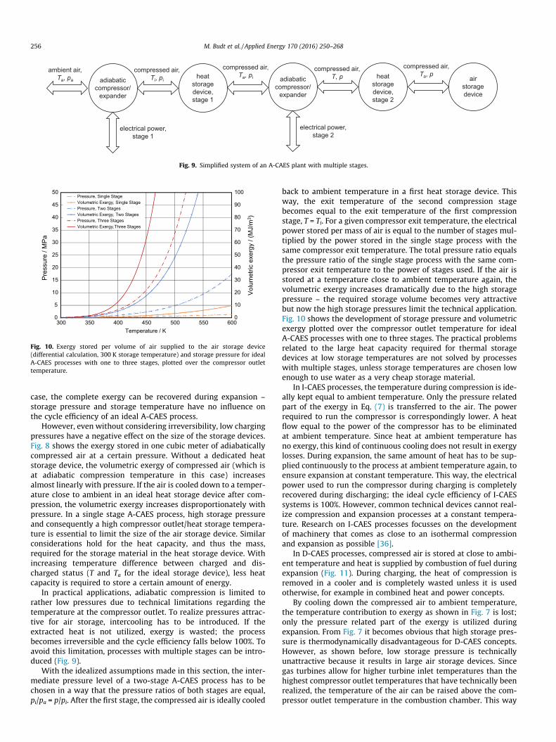
However, even without considering irreversibility, low chargingpressures have a negative effect on the size of the storage devices.Fig. 8 shows the exergy stored in one cubic meter of adiabaticallycompressed air at a certain pressure. Without a dedicated heatstorage device, the volumetric exergy of compressed air (which isat adiabatic compression temperature in this case) increasesalmost linearly with pressure. If the air is cooled down to a temper-ature close to ambient in an ideal heat storage device after com-pression, the volumetric exergy increases disproportionately withpressure. In a single stage A-CAES process, high storage pressureand consequently a high compressor outlet/heat storage tempera-ture is essential to limit the size of the air storage device. Similarconsiderations hold for the heat capacity, and thus the mass,required for the storage material in the heat storage device. Withincreasing temperature difference between charged and dis-charged status (T and Ta for the ideal storage device), less heatcapacity is required to store a certain amount of energy.
In practical applications, adiabatic compression is limited torather low pressures due to technical limitations regarding thetemperature at the compressor outlet. To realize pressures attrac-tive for air storage, intercooling has to be introduced. If theextracted heat is not utilized, exergy is wasted; the processbecomes irreversible and the cycle efficiency falls below 100%. Toavoid this limitation, processes with multiple stages can be intro-duced (Fig. 9).
With the idealized assumptions made in this section, the inter-mediate pressure level of a two-stage A-CAES process has to bechosen in a way that the pressure ratios of both stages are equal,pi/pa = p/pi. After the first stage, the compressed air is ideally cooled
back to ambient temperature in a first heat storage device. Thisway, the exit temperature of the second compression stagebecomes equal to the exit temperature of the first compressionstage, T = Ti. For a given compressor exit temperature, the electricalpower stored per mass of air is equal to the number of stages mul-tiplied by the power stored in the single stage process with thesame compressor exit temperature. The total pressure ratio equalsthe pressure ratio of the single stage process with the same com-pressor exit temperature to the power of stages used. If the air isstored at a temperature close to ambient temperature again, thevolumetric exergy increases dramatically due to the high storagepressure – the required storage volume becomes very attractivebut now the high storage pressures limit the technical application.Fig. 10 shows the development of storage pressure and volumetricexergy plotted over the compressor outlet temperature for idealA-CAES processes with one to three stages. The practical problemsrelated to the large heat capacity required for thermal storagedevices at low storage temperatures are not solved by processeswith multiple stages, unless storage temperatures are chosen lowenough to use water as a very cheap storage material.
In I-CAES processes, the temperature during compression is ide-ally kept equal to ambient temperature. Only the pressure relatedpart of the exergy in Eq. (7) is transferred to the air. The powerrequired to run the compressor is correspondingly lower. A heatflow equal to the power of the compressor has to be eliminatedat ambient temperature. Since heat at ambient temperature hasno exergy, this kind of continuous cooling does not result in exergylosses. During expansion, the same amount of heat has to be sup-plied continuously to the process at ambient temperature again, toensure expansion at constant temperature. This way, the electricalpower used to run the compressor during charging is completelyrecovered during discharging; the ideal cycle efficiency of I-CAESsystems is 100%. However, common technical devices cannot real-ize compression and expansion processes at a constant tempera-ture. Research on I-CAES processes focusses on the developmentof machinery that comes as close to an isothermal compressionand expansion as possible [36].
In D-CAES processes, compressed air is stored at close to ambi-ent temperature and heat is supplied by combustion of fuel duringexpansion (Fig. 11). During charging, the heat of compression isremoved in a cooler and is completely wasted unless it is usedotherwise, for example in combined heat and power concepts.
By cooling down the compressed air to ambient temperature,the temperature contribution to exergy as shown in Fig. 7 is lost;only the pressure related part of the exergy is utilized duringexpansion. From Fig. 7 it becomes obvious that high storage pres-sure is thermodynamically disadvantageous for D-CAES concepts.However, as shown before, low storage pressure is technicallyunattractive because it results in large air storage devices. Sincegas turbines allow for higher turbine inlet temperatures than thehighest compressor outlet temperatures that have technically beenrealized, the temperature of the air can be raised above the com-pressor outlet temperature in the combustion chamber. This way

ambient air,Ta, pa
compressed air,T, p
adiabaticcompressor
cooling
electrical power
ambient air,Ta, pa
compressed air,T, p
adiabaticexpander
combustionchamber
electrical power
Charging Mode
Discharging Mode
airstoragedevice
compressed air,Ta, p
waste heat
airstoragedevice
compressed air,Ta, p
fuel
Fig. 11. Simplified system of a D-CAES plant.
Fig. 12. Relative deviations between isobaric heat capacities of dry air, which werecalculated using ideal gas [38] and real gas [40] property models, see also [37,39].
0
2
4
6
8
10
300 350 400 450 500 550
Air / Water, xH2O = 0.01 - 0.50
0.1 MPa
1 MPa
10 MPa
Saturation temperature Ts,real / K
T s,id
eal-T s
,real
/ K
Fig. 13. Deviations between saturation temperatures calculated based on asimplified saturation model and based on a recent reference model [41].
M. Budt et al. / Applied Energy 170 (2016) 250–268 257
more electrical power is gained during expansion, but at theexpense of further increased losses. In this case, the air leavesthe expander at a temperature above ambient temperature evenunder ideal conditions and exergy gets lost with the flue gas, unlessthis exergy is utilized in some kind of exhaust-heat recoverysystem.
Thermodynamically, D-CAES concepts become more attractiveif the compression is carried out isothermally at ambient temper-ature or, as a technical approximation, with multiple intercoolers.This way the power required to drive the compressor is reduced,ideally to the pressure contribution to the exergy, see Eq. (7). Dur-ing expansion, this power can be regained effectively. However,existing D-CAES plants work with adiabatic compression andexpander exit temperature well above ambient temperature. Cycleefficiencies are correspondingly poor.
Real CAES processes deviate significantly from the resultsshown in this section. Irreversibilities in all sub-processes are byfar not negligible and the relations given and used to generatethe figures hold only for ideal gas with constant heat capacity –
only Eq. (4) holds for real air, too. However, the general findings,such as the distinction of temperature and pressure related contri-bution to stored exergy, the process dependent relations betweenstorage pressure and volumetric exergy of the stored air, and thefact that high cycle efficiencies do not require high storage temper-atures can be translated into real processes and are helpful for thediscussion in Sections 3–6.
3.3. Real gas properties of air
In most applications in energy technologies, air is treated as anideal gas. Well established standards define how properties for airhave to be calculated under this assumption [37–39]. Both the pre-vailing standards set by VDI (Verein Deutscher Ingenieure) [37]and by ASME (American Society of Mechanical Engineers) [39]use a plot like the one depicted in Fig. 12 to illustrate the limitsof the ideal gas assumption. For dry air, Fig. 12 shows relativedeviations between isobaric heat capacities calculated for dry airas ideal and as real gas; the isobaric heat capacity is used as an

258 M. Budt et al. / Applied Energy 170 (2016) 250–268
example for technically relevant thermodynamic properties. Devi-ations between ideal and real gas increase with increasing pressureand decrease with increasing temperature. For a typical adiabaticcompression process starting at ambient temperature ideal gasmodels may be applied up to high pressure, because the air heatsup during compression – deviations from the ideal gas assumptionremain technically acceptable throughout the compression pro-cess. However, this assumption does not hold if the air is cooleddown at high pressure, as is done in all kinds of CAES processes.In this case, deviations between ideal and real gas models becomeinacceptable and ideal gas models cannot be used for accuratetechnical calculations.
To consider real gas effects, the ASME standard [39] suggeststhat a model representing an ideal mixture of real gases shouldbe used. For dry air, this model yields accurate results in the tem-perature and pressure range relevant for CAES. However, CAES useshumid air as working fluid. Water contained in the ambient air iscondensed during inter- and final cooling of the compressed air.Optimized concepts with heat storage have to humidify thereheated air before expansion to increase the mass flow in theexpansion devices and to utilize the stored heat efficiently. Thus,the saturation temperature of humid air at elevated pressure isan important parameter in designing a CAES process.
In simplified property models, the saturation temperature iscommonly calculated using the ideal gas/pure liquid assumption,which implies that saturation is reached when the partial pressureof water in humid air is equal to the vapor pressure of water at thecorresponding temperature. Fig. 13 shows deviations betweensaturation temperatures calculated according to this simplifiedassumption Ts,ideal and saturation temperatures Ts.real calculatedusing a recent reference model for thermodynamic properties ofhumid air and combustion gas like mixtures [41]. While deviationsare technically acceptable up to pressures of about 1 MPa, devia-tions at higher pressure may lead to substantially suboptimaldesigns – an overestimation of saturation temperatures by severalK is not acceptable for accurate process design. Appropriate realgasmodels have to be used to design high-pressure CAES processes.
A number of thermodynamic models have been published forthe calculation of humid air properties. Goff and Gratch [42] andlater Hyland and Wexler [43] developed virial models with secondand third binary cross-virial coefficients fitted to experimentaldata. The virial equation of state by Rabinovich and Beketov [44]uses cross-virial coefficients calculated from theoretical modelsbased on intermolecular interactions with the use of theLennard-Jones potential. Ji and Yan [45] used a modified Redlich–Kwong cubic equation of state in combination with correlationequations for the enthalpy and entropy of the ideal gas for thedescription of humid air up to 20 MPa and 573 K. Lately, ab initiomodels for several water–gas mixtures (see e.g. [46] for the systemwater + nitrogen) were developed, from which second cross-virialcoefficients are calculated. Detailed descriptions of different mod-els and experimental data available for thermophysical propertiesof humid air are given in [47–49]. More recently, reference modelstreating humid air as mixture of the main air components andwater were published [41,50]. Software solutions implementingthese models are available. Due to their numerical complexity,the reference models may not be used directly in all applications.However, they provide a sound basis to check the accuracy of indi-vidual solutions for the calculation of thermodynamic properties ofhumid air.
4. Diabatic compressed air energy storage
The world’s first CAES plant was put into operation in 1978 nearthe northern German village of Huntorf with an output power of
290 MW [5]. A second one with 110 MW output power was builtin McIntosh/Alabama in the USA in 1991 [12]. Both plants are ofthe D-CAES type, use solution mined salt caverns as CAS, and havesuccessfully been in operation up to now. Moreover, several smal-ler installations in the form of demonstration projects exist inJapan and Italy. Most of them are not in operation anymore.In the following, technical characteristics of the Huntorf andMcIntosh plants will be presented.
4.1. Huntorf plant
In the Huntorf plant ambient air is compressed in an intercooledprocess by two separate turbo-compressor units to a maximumpressure of 72 bar. Before it is stored in the CAS, the air is recooledagain (Fig. 14). The intercooled two-stage compression processlimits exergy losses of the diabatic process design without heatstorage device, but still more than 25% of the exergy supplied aselectrical energy during compression is wasted due to cooling.
The CAS consists of two solution mined salt caverns with a totalstorage volume of about 310,000 m3. The CAS is made up of twocaverns to guarantee high availability by facilitating plant opera-tion even when one of the caverns is being maintained. Duringoperation, the caverns never reach ambient pressure again, beingcycled between approximately 46 and 72 bar. In emergency cases,the expansion train can be operated below 46 bar, too. Identical tothe compression process (Comp), expansion (Exp) is carried out intwo separate units in series. When the air leaves the cavern inexpansion mode, it is first throttled down to a constant pressureof approx. 42 bar before entering the high pressure (HP) combus-tion chamber (point (1) in Fig. 14) [5]. Throttling of the air resultsin considerable exergy losses but allows for constant pressureoperation of the HP combustion chamber and the HP turbine.Downstream of the HP combustion chamber (2) the air now heatedup to 490 �C by the specific heat qHP-C is being expanded down toabout 10 bar in the HP turbine (3), which is a derivate of a steamturbine. On this pressure level the air is heated up again to945 �C in the low pressure (LP) combustion chamber by the specificheat qLP-C before entering the LP turbine. Both components arebased on conventional gas turbine technology.
In 2006, after 28 years of operation, the whole expansion trainwas retrofitted. One retrofit measure was to lower the inlet tem-perature of the HP turbine (2) from 550 �C to now 490 �C, keepingthe inlet pressure as before. In the LP combustion chamber, theprocess parameters were raised from 10 bar/825 �C to13 bar/945 �C (4). As a consequence, the output power could beincreased from 290 MW to 321 MW [51]. The exergy of the exhaustgas leaving the LP turbine at approximately 480 �C (5) is still notutilized in any way.
As can be seen in Fig. 15 as well as in the process scheme ofFig. 14, compression and expansion train are connected to eachother by the electric machine. In this way, the electric machine actsas both, electric motor and- generator (M/G), and is coupled to theturbomachinery trains via a clutch on each side. Since the highpressure compressor works at elevated rotational speed, it is cou-pled by a gear box [52].
In recent years, the Huntorf plant has been operated as a reserveplant providing tertiary control reserve and for internal portfoliooptimization. Moreover, the plant has black start capability andis able to provide reactive power, too. The provision of reactivepower and frequency regulation can be performed even whenthe plant is neither charging nor discharging by opening bothclutches. In this way, the synchronous machine can be operatedidling in parallel to the grid. The described field of application leadsto a small number of generator operational hours in the range of200 h per year [51].

HP Comp
HP Exp LP ExpLP Comp
C
Compressed Air Storage (CAS)
C
1
2 3 4 5
1
qHP-C
qLP-C
s
T
2
3
4
5
M/G
Fig. 14. Simplified process scheme and T,s-diagram of the expansion process of the Huntorf plant according to [32].
Fig. 15. View of the machine hall of the Huntorf CAES plant (Courtesy of E.ONKraftwerke).
M. Budt et al. / Applied Energy 170 (2016) 250–268 259
As a first-of-its-kind plant the Huntorf CAES plant came up withsome unique features being implemented for the first time [51]:
– Compressed air storage in solution mined salt caverns.– High pressure combustion chamber.– High pressure expansion turbine and gas turbine with fast start-up capability.
– Power ratio motor/generator of one to five.
Despite this high density of innovations, a safe plant operationat high availability could be realized [51,53].
4.2. McIntosh plant
In 1991, 13 years after the installation of the Huntorf plant, asecond large scale D-CAES plant was realized in McIntosh/Alabama[54]. The basic arrangement applying a motor generator in a singleshaft design is essentially the same as in the Huntorf plant asdepicted in Fig. 16. Even an underground mined salt cavern waschosen for the CAS. In contrast to the Huntorf plant, the CAS con-sists of only one large salt cavern with a total volume of538,000 m3 [55].
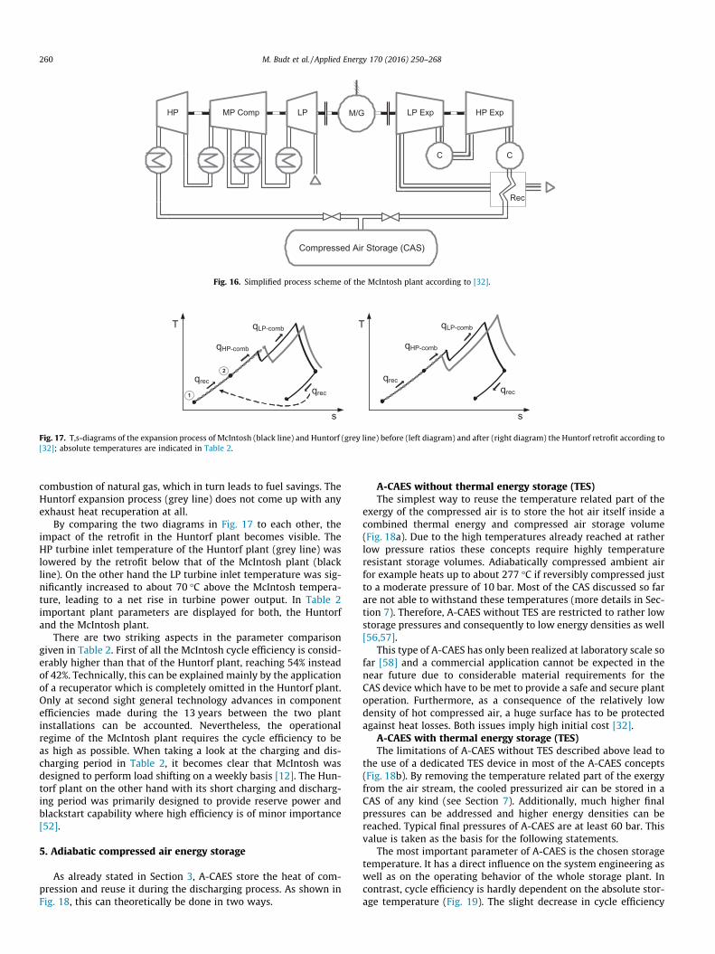
Similar to the Huntorf plant the McIntosh plant has no devicefor heat storage. However, multiple-stage intercooling reducesexergy losses during compression further. The usage of anexhaust-heat recuperator (Rec) poses the main difference andadvancement compared to Huntorf. During expansion mode, thestill hot exhaust gases of the LP expander (370 �C) are used to pre-heat the compressed air flowing out of the cavern. In this way thecompressed air is heated to about 295 �C by the specific heat qrecbefore entering the HP combustion chamber, where the specificheat qHP-comb is added too. After expansion in the HP expanderthe air is reheated in the LP combustion chamber by the specificheat qLP-comb to increase the power output of the LP expander. How-ever, the exergy remaining in the exhaust gas is increased as well,because the pressure ratio of the LP expander is by far too small tocool down the exhaust gas to a temperature close to ambient tem-perature. The recuperator is applied as a simple form of exhaust-heat recovery to limit the exergy losses which would result fromthe hot exhaust gas otherwise. Fig. 17 gives a comparative over-view using T,s-diagrams of the expansion process of the McIntoshplant (black line) and Huntorf plant (grey line). The left diagramcompares the Huntorf and McIntosh expansion processes beforethe Huntorf retrofit in 2006. The diagram on the right hand sideof Fig. 17 shows the same comparison after the Huntorf retrofitwith modified turbine inlet parameters [12,51].
The dotted arrow in the left diagram in Fig. 17 indicates thetransfer of heat of the exhaust gases qrec. In doing so, the cold inletair of the McIntosh plant is heated up from (1), (2). Consequently,only the remaining enthalpy difference from 295 �C to theHP-turbine inlet temperature of 538 �C has to be provided by
MP CompHP LP Exp HP ExpLP
C
Rec
Compressed Air Storage (CAS)
C
M/G
Fig. 16. Simplified process scheme of the McIntosh plant according to [32].
qrecqrec
qHP-comb
qLP-comb
s
T
s
T
1
2qrec
qrec
qHP-comb
qLP-comb
Fig. 17. T,s-diagrams of the expansion process of McIntosh (black line) and Huntorf (grey line) before (left diagram) and after (right diagram) the Huntorf retrofit according to[32]; absolute temperatures are indicated in Table 2.
260 M. Budt et al. / Applied Energy 170 (2016) 250–268
combustion of natural gas, which in turn leads to fuel savings. TheHuntorf expansion process (grey line) does not come up with anyexhaust heat recuperation at all.
By comparing the two diagrams in Fig. 17 to each other, theimpact of the retrofit in the Huntorf plant becomes visible. TheHP turbine inlet temperature of the Huntorf plant (grey line) waslowered by the retrofit below that of the McIntosh plant (blackline). On the other hand the LP turbine inlet temperature was sig-nificantly increased to about 70 �C above the McIntosh tempera-ture, leading to a net rise in turbine power output. In Table 2important plant parameters are displayed for both, the Huntorfand the McIntosh plant.
There are two striking aspects in the parameter comparisongiven in Table 2. First of all the McIntosh cycle efficiency is consid-erably higher than that of the Huntorf plant, reaching 54% insteadof 42%. Technically, this can be explained mainly by the applicationof a recuperator which is completely omitted in the Huntorf plant.Only at second sight general technology advances in componentefficiencies made during the 13 years between the two plantinstallations can be accounted. Nevertheless, the operationalregime of the McIntosh plant requires the cycle efficiency to beas high as possible. When taking a look at the charging and dis-charging period in Table 2, it becomes clear that McIntosh wasdesigned to perform load shifting on a weekly basis [12]. The Hun-torf plant on the other hand with its short charging and discharg-ing period was primarily designed to provide reserve power andblackstart capability where high efficiency is of minor importance[52].
5. Adiabatic compressed air energy storage
As already stated in Section 3, A-CAES store the heat of com-pression and reuse it during the discharging process. As shown inFig. 18, this can theoretically be done in two ways.
A-CAES without thermal energy storage (TES)The simplest way to reuse the temperature related part of the
exergy of the compressed air is to store the hot air itself inside acombined thermal energy and compressed air storage volume(Fig. 18a). Due to the high temperatures already reached at ratherlow pressure ratios these concepts require highly temperatureresistant storage volumes. Adiabatically compressed ambient airfor example heats up to about 277 �C if reversibly compressed justto a moderate pressure of 10 bar. Most of the CAS discussed so farare not able to withstand these temperatures (more details in Sec-tion 7). Therefore, A-CAES without TES are restricted to rather lowstorage pressures and consequently to low energy densities as well[56,57].
This type of A-CAES has only been realized at laboratory scale sofar [58] and a commercial application cannot be expected in thenear future due to considerable material requirements for theCAS device which have to be met to provide a safe and secure plantoperation. Furthermore, as a consequence of the relatively lowdensity of hot compressed air, a huge surface has to be protectedagainst heat losses. Both issues imply high initial cost [32].
A-CAES with thermal energy storage (TES)The limitations of A-CAES without TES described above lead to
the use of a dedicated TES device in most of the A-CAES concepts(Fig. 18b). By removing the temperature related part of the exergyfrom the air stream, the cooled pressurized air can be stored in aCAS of any kind (see Section 7). Additionally, much higher finalpressures can be addressed and higher energy densities can bereached. Typical final pressures of A-CAES are at least 60 bar. Thisvalue is taken as the basis for the following statements.
The most important parameter of A-CAES is the chosen storagetemperature. It has a direct influence on the system engineering aswell as on the operating behavior of the whole storage plant. Incontrast, cycle efficiency is hardly dependent on the absolute stor-age temperature (Fig. 19). The slight decrease in cycle efficiency
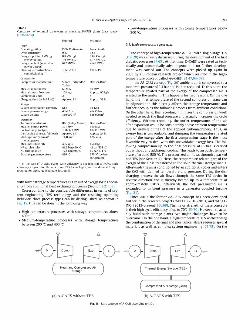
Table 2Comparison of technical parameters of operating D-CAES plants (data source:[12,15,51,55]).
Huntorf McIntosh
PlantOperating utility E.ON Kraftwerke PowerSouthCycle efficiencya 0.42 0.54Energy input for 1 kW hel
energy output0.8 kW hel/1.6 kW hgas
0.69 kW hel/1.17 kW hgas
Energy content (related topower output)
642 MW h 2640 MW h
Planning – construction –commissioning
1969–1978 1988–1991
CompressionCompressor manufacturer Sulzer (today MAN
Turbo)Dresser-Rand
Max. el. input power 60 MW 50 MWMax. air mass flow rate 108 kg/s Approx. 90 kg/sCompressor units 2 4Charging time (at full load) Approx. 8 h Approx. 38 h
StorageCavern construction company KBB PB-KBBCavern pressure range 46–72 bar 46–75 barCavern volume 310,000 m3 538,000 m3
ExpansionTurbine manufacturer BBC (today Alstom) Dresser-RandMax. el. output power 321 MW 110 MWControl range (output) 100–321 MW 10–110 MWDischarging time (at full load) Approx. 2 h Approx. 24 hStart-up time (normal/
emergency)14/8 min 12/7 min
Max. mass flow rate 455 kg/s 154 kg/sHP turbine inlet 41.3 bar/490 �C 42 bar/538 �CND turbine inlet 12.8 bar/945 �C 15 bar/871 �CExhaust gas temperature 480 �C 370 �C (before
recuperator)
a In the case of D-CAES plants cycle efficiency is not identical to AC/AC cycleefficiency as given for the other pure EES technologies, since additional firing isrequired for discharge (compare Section 3).
M. Budt et al. / Applied Energy 170 (2016) 250–268 261
with lower storage temperatures is a result of exergy losses occur-ring from additional heat exchange processes (Section 3.2) [59].
Corresponding to the considerable differences in terms of sys-tem engineering, TES technology and the resulting operatingbehavior, three process types can be distinguished. As shown inFig. 19, this can be done in the following way:
� High-temperature processes with storage temperatures above400 �C.
� Medium-temperature processes with storage temperaturesbetween 200 �C und 400 �C.
M
Heat- and Compressed Air Storage
ExpComp G
(a) A-CAES without TES
Fig. 18. Basic concepts of A-
� Low-temperature processes with storage temperatures below200 �C.
5.1. High-temperature processes
The concept of high-temperature A-CAES with single-stage TES(Fig. 20) was already discussed during the development of the firstdiabatic processes [7,63]. At that time, D-CAES were rated as tech-nically and economically advantageous and no further develop-ment was carried out. The concepts were picked up again in2003 by a European research project which resulted in the high-temperature concept called AA-CAES [31,47,64–67].
In the AA-CAES concept (Fig. 20) ambient air is compressed to amoderate pressure of 2.4 bar and is then recooled. To this point, thetemperature related part of the exergy of the compressed air iswasted to the ambient. This happens for two reasons. On the onehand, the inlet temperature of the second compression stage canbe adjusted and this directly affects the storage temperature andfurther decouples the following process from ambient conditions.On the other hand, this recooling minimizes the compression workneeded to reach the final pressure and actually increases the cycleefficiency. Without recooling, the outlet temperature of the airafter expansion would be considerably above ambient temperaturedue to irreversibilities of the applied turbomachinery. Thus, anexergy loss is unavoidable, and dumping the temperature relatedpart of the exergy after the first compression stage is the mostfavorable way to deal with this unavoidable exergy loss. The fol-lowing compression up to the final pressure of 65 bar is carriedout without any additional cooling. This leads to an outlet temper-ature of around 580 �C. The pressurized air flows through a packedbed TES (see Section 7). Here, the temperature related part of theexergy of the air is transferred to the solid thermal storage media.Afterwards the air is conditioned by an additional cooler and entersthe CAS with defined temperature and pressure. During the dis-charging process the air flows through the same TES device inreverse direction and is thereby heated up to a temperature ofapproximately 570 �C. Afterwards the hot pressurized air isexpanded to ambient pressure in a generator-coupled turbine(Fig. 21).
Since 2010, the former AA-CAES concept has been developedfurther in the research projects ‘ADELE’ (2010–2013) and ‘ADELE-ING’ (2013-present) [60,68]. The major strength of these conceptsis their high cycle efficiency of up to 70% [69,70]. However, to actu-ally build such storage plants two major challenges have to beovercome. On the one hand, a high-temperature TES withstandingthe combination of thermal and mechanical stress requires specialmaterials as well as complex system engineering [71,72]. On the
Compressed Air Storage (CAS)
Thermal Energy Storage (TES)
Comp GM Exp
(b) A-CAES with TES
CAES according to [32].

0.0
0.1
0.2
0.3
0.4
0.5
0.6
0.7
0.8
0 100 200 300 400 500 600 700 800
Storage temperature [°C]
Cyc
le e
ffici
ency
[-]
2 2 1
3
33
4
High-temperature processesMedium-Low-
5 5 55
Fig. 19. Predicted cycle efficiencies of A-CAES depending on storage temperature(1 = [60], 2 = [32], 3 = [33], 4 = [61], 5 = [62]) based on [59].
TES
CAS
ExpM
M Comp
Comp G
Fig. 20. Block diagram of a high-temperature A-CAES [32] as it was designed in theAA-CAES project.
273
373
473
573
673
773
873
5 5.5 6 6.5 7 7.5 8
Tem
pera
ture
T [K
]
Entropy s [kJ/kgK]
ExpansionCompression
1 bar2.4 bar65 bar
Fig. 21. T,s-diagram of a high-temperature A-CAES in AA-CAES layout (data source:[32]).
262 M. Budt et al. / Applied Energy 170 (2016) 250–268
other hand, there is no electrically driven compressor available off-the-shelf that operates at the high-outlet temperature planned inAA-CAES. In general such machinery is technically feasible but aconsiderable engineering effort is needed to apply knowledge fromgas turbine technology to an electrically driven compressor.
As in all other A-CAES concepts, humidity in the air will con-dense in the TES and/or in heat exchangers. Depending on ambientconditions and process layout, the related enthalpy of condensa-tion may have a considerable and frequently neglected impact onheat balances. To avoid mismatches in the energy balance of charg-ing and discharging, and to optimize the power output of the
system, condensed water should be reinjected into the processduring discharge in a suitable way; see Section 3.3 for a brief dis-cussion on suitable property models.
With regard to energy economics the reaction time of a storagetechnology is a major parameter since storage devices with shorterreaction times are able to participate in additional, lucrative mar-kets [73]. Talking about CAES, the dominating reaction time isthe start-up time of the system from cold conditions. Due to ther-mal stress, high-temperature A-CAES plants need 10–15 min for astart-up process if the tolerable thermal gradients are respected[32]. In terms of start-up times, high-temperature A-CAES are asflexible as gas turbines, but rather slow compared to PHES, whichare able to start-up within two minutes [74].
5.2. Medium-temperature processes
A-CAES concepts with two-stage TES and therefore lower tem-peratures have also been discussed since the beginning of CAESdevelopment [7,75,76]. In order to avoid the need for extensiveresearch and development efforts, the process temperature is low-ered below 400 �C by transferring the temperature dependent partof the exergy of the compressed air to TES devices twice (Fig. 22).
The slightly lower cycle efficiency (compare Fig. 19) is compen-sated by the applicability of the off-the-shelf compressor-technology and TES media like molten salt or thermal oil whichare already used in similar applications [77]. Thermal storage inconventional or PCM-filled packed bed TES is possible as well[69,78,79]. Due to these advantages, medium-temperature pro-cesses are also in the focus of current research [32,68,80]. Besidethese technical advantages, the economically relevant start-uptime is still in the range of 10–15 min due to high thermal stress[32].
In the medium-temperature A-CAES shown in Fig. 22, ambientair is compressed to 2.4 bar in a first stage and is further com-pressed to 19 bar in a second stage after intermediate recooling(see also Fig. 23). The air leaves the second stage at about 380 �Cand is cooled down again by flowing through a first TES deviceand an aftercooler. Afterwards the air is compressed to the finalpressure and thus heated up to about 380 �C again, followed byheat exchange in a second TES device and storage in the CAS. Thedischarge process involves two expansion stages with preheatingby the two TES devices [32].
5.3. Low-temperature processes
Basically, the idea to use storage temperatures below 200 �C isnot new [7], but detailed concepts are results of current research[33,59,61,81–84]. The major advantages of low-temperatureA-CAES are the applicability of liquid TES media, which can bepumped and which enable the use of common heat exchangers,and the applicability of off-the-shelf compression and expansiondevices. To reach low storage temperatures in combination withstill acceptable energy density, heat transfer after every singlestage is used (Fig. 24). As a further advantage, storage plants of thiskind would be able to start-up within 5 min, which allows the par-ticipation in additional energy markets [33].
A basic concept of a low-temperature A-CAES plant with liquidTES media and two tank TES is shown in Fig. 24. Depending on thestate of charge, the liquid is stored inside the hot tank in case ofcharged storage or inside the cold storage tank otherwise. Duringthe charging and the discharging process, the liquid is pumpedthrough the heat exchangers to cool or preheat the air, respec-tively. Such an active TES system requires more advanced controlcompared to passive TES systems, but enables enhanced processcontrol as well.

Comp
Comp
TES
CAS
Exp
TES
Exp
Comp
M
M
M
G
Fig. 22. Block diagram of a medium-temperature A-CAES (Ref. [32]).
273
373
473
573
673
773
873
5 5.5 6 6.5 7 7.5 8
Tem
pera
ture
T [K
]
Entropy s [kJ/kgK]
ExpansionCompression
19 bar 2.4 bar 1 bar12 bar150 bar
Fig. 23. T,s-diagram of a medium-temperature A-CAES (data source: [32]).
M. Budt et al. / Applied Energy 170 (2016) 250–268 263
The concept shown in Fig. 24 is designed to work with five com-pressor and expander stages and heat exchange between each ofthese. The pressure ratio of each stage is identical and storage tem-
ComCompCompCompM
TES(hot)
TES(cold)
ExpExpExpExp
Fig. 24. Block diagram of a low
perature is limited to about 132 �C at a final pressure of 200 bar(Fig. 25) [82].
6. Isothermal compressed air energy storage
I-CAES try to prevent temperature increase in the compressorsduring charging and temperature drop during discharging in theexpansion devices. All I-CAES concepts known so far are based onpiston machinery since these machines can perform a comparablyslow compression or expansion process which leaves enough timefor heat exchange processes inside the machinery itself. For exam-ple, the heat exchange can be carried out using additional heatexchange surfaces and a liquid piston [85]. Another way is to sprayliquids into the plug room of a common piston machine or thecompression of a pre-mixed foam [86].
The concept of I-CAES was implemented in so called hydro-pneumatic energy storage first. In these devices a liquid is usedto compress the gas. In the case of closed cycle hydro-pneumaticenergy storage (C-HyPES) this is achieved by pumping a liquid,for example hydraulic oil, into the storage tank, where the gas vol-ume is reduced, which in turn causes a rise in gas pressure(Fig. 26). When electricity is needed, the gas pressure is released
CAS
Compp
Exp G
-temperature A-CAES [82].

273
373
473
573
673
773
873
5 5.5 6 6.5 7 7.5 8
Tem
pera
ture
T [K
]
Entropy s [kJ/kgK]
ExpansionCompression
200 bar 69 bar 24 bar 8.3 bar 1 bar2.9 bar
Fig. 25. T,s-diagram of a low-temperature A-CAES (data source: [82]).
264 M. Budt et al. / Applied Energy 170 (2016) 250–268
by letting the liquid flow in reverse direction through the pumpturbine (P/T), which now acts as a turbine driving the generator[32]. The major drawback of C-HyPES is their low energy density.For this reason these systems have not been built commercially,yet, but are subject to investigation at laboratory scale [85,87].
To overcome the drawbacks of C-HyPES, an open cycle concept(O-HyPES) combines the higher energy densities of air–air systemswith the advantages of applying a liquid as working medium. In anO-HyPES system, air is compressed by a liquid piston before enter-ing the CAS at high pressure (Fig. 26). This concept requires at leasttwo alternating cylinders, where a liquid can be pumped into andout of, and a system of valves allowing a cyclic air supply andrelease [32].
In contrast to the closed cycle system, O-HyPES has been real-ized not only at laboratory scale [88] but has been further devel-oped to a utility scale storage unit. A first pilot plant with a ratedpower of 2 MW was built in Texas and has been in test operationsince 2012 [89].
In both concepts charging and discharging power is limited bythe heat exchange surface formed by the liquid surface in contactwith the gas. At high power, temperature gradients increase andthe efficiency of the no longer isothermal process decreases. Thislimitation can be overcome by spraying water into the compres-sion chamber, which results in a huge water surface in contactwith the gas [27]. This way an efficient heat transfer is reachedand the use of common piston technology becomes possible. Ofcourse, corresponding piston compressors/expanders have to bemodified to withstand the water content inside. Latest result ofthis research is the compression of a pre-mixed foam to furtherincrease the heat transfer [86]. A first full-scale prototype storing
P/T
Air
Oil
OilM/G
Fig. 26. Simplified process scheme of a C-H
air and water together inside an aboveground steel pipe CAS (com-pare Section 7) has been in test operation since the end of 2013.
In particular in open cycle concepts (O-HyPES) effects related tothe humidity of ambient air and to the saturation water content ofair at operating conditions have to be taken into account carefully.Condensate may affect the properties of the used hydraulic oil andthe cooling capacity of sprayed water is closely related to evapora-tion which may be followed by condensation once a higherpressure-level is reached.
7. Compressed air storage
Compressed air can be stored either at constant volume (iso-choric) or at constant pressure (isobaric). In case of constant vol-ume storage, the pressure varies and thus indicates the state ofcharge. The most common example of isochoric storage is a steelpressure vessel or, at large scale, a salt cavern. Constant pressurestorage requires a varying volume to maintain pressure at a con-stant level while charging and discharging. In this case, the volumeindicates the state of charge. Constant pressure storage can techni-cally be realized using, e.g., a hydraulically compensated reservoirwhere pressure is kept approximately constant by a second reser-voir of liquid at elevated geodetic height as depicted in the centerof Fig. 27 [32].
The major drawback of isochoric CAS is their effect on the com-pression and expansion machinery. These machines have to followthe changing pressure and are therefore not operating in theirdesign pressure ratio, which leads to lower efficiencies. In case ofD-CAES using an isochoric CAS, like the plants in Huntorf andMcIntosh, the cavern pressure above the tolerable pressure of thecombustion chamber even has to be throttled (Section 4.1). LatestD-CAES concepts overcome the exergy loss due to throttling by theimplementation of flexible expander stages between CAS and thefirst combustion chamber [25]. Isobaric storage volumes do notaffect the machinery in that way, but are more complex and notwidespread.
In principle, isochoric and isobaric CAS are both applicableabove- and underground. Aboveground CAS can be built of steelor sandwich material tanks or pipes. Even concrete storage vol-umes are possible when thinking of lower final pressures. Themajor characteristics of aboveground CAS are:
� installable widely location-independent,� high pressure difference resulting in high energy densitiesrealizable,
� high specific investment costs,� high land consumption even at moderate storage sizes,� need for regular pressure and security tests.
P/T
Air
OilOil
Air
CAS
M/G
yPES (left) and an O-HyPES (right) [32].

CompressedAir
Liquid
CompressedAir
Liquid
isochoric storage
isobaric storage
cryogenic storage
Liquid Air
Fig. 27. Different types of air storage devices according to [32].
M. Budt et al. / Applied Energy 170 (2016) 250–268 265
For the application of underground CAS a variety of choicesexists. In general, each underground cavity, which is able to with-stand the needed pressure and which is air tight, can be used. Solu-tion mined salt caverns, gas fields or mine shafts are just somepossibilities. Major characteristics of all these CAS are:
� low aboveground land consumption,� low specific investment costs,� depending on usable geology,� limited pressure difference due to rock mechanic stability.
For large scale CAS systems, salt caverns are the dominatingtechnology as they are the only choice implemented for com-pressed air energy storage in commercial application so far; thebehavior of pressurized salt caverns has been known from the stor-age of natural gas for decades. Both existing D-CAES plants usesolution mined salt caverns as isochoric CAS [12,53]. Constructionof salt caverns is a state of the art procedure. The salt formationsthey are built in are air tight by nature as long as the temperatureof the stored air stays below the site specific and depth dependentmaximum allowed temperature. To keep the cavern stable, there isalso a demand for a minimum operation pressure to withstand theouter forces from the surrounding rock [90]. The air in the caverncan generally be considered saturated with water at cavern pres-sure and temperature. Condensation and evaporation of water inthe cavern can be highly relevant for the stability of the cavern.
An isobaric salt cavern was planned for a D-CAES is the USA, buthas never been constructed, just as the plant itself [10]. Based onexperience with the use of isobaric salt caverns for the storage ofhydrogen (Teesside, UK), there are still CAES concepts encompass-ing the use of isobaric salt caverns with brine shuttle ponds[91,92].
The use of other geological underground formations has so farjust been tested but has never been used commercially for air stor-age. Aquifer storage tests were carried out especially in the USA inthe early 1980s. A good overview on results of a field test at thePittsfield aquifer is given in [93,94]. Air injection and withdrawalgenerally was found to be feasible at Pittsfield, but various wellswould have been needed to reach the air flow required, whichwould have led to increased drilling costs. In Europe, Italy showedsome interest in aquifers for CAES purposes as well. In 1986, a testinstallation was put into operation at Sesta using an aquifer in ageothermal region at an underground temperature of 110 �C [95].
To summarize, it can be stated that compressed air storage in aqui-fers is generally feasible, but was not employed so far on a com-mercial basis, essentially due to the high risks of not beingsuccessful in drilling and in the site selection process. In the USAnew interest in aquifers for CAES arose at the Dallas Center Iowaaquifer structure. Careful site examination by acoustic geophysicallogs and model based analysis was undertaken [96]. Neverthelessthe project was canceled because test results with the first wellshow much lower volume flow than planned [97].
Since geologic salt formations do not exist in Japan, the Japa-nese focus is on using exploited mines as compressed air reservoir.One site is reported at Kamioka in the Gifu prefecture using a for-mer zinc mine at 1000 m depth for testing purposes [98]. A closedvolume of 200 m3 was created by sealing a part of the mine by aconcrete plug. The cavern is filled to a maximum pressure of7 bar, but air tightness could not be achieved since no measuresfor sealing the interior of the cavern were undertaken. AnotherJapanese testing cavern uses a former coal mine at Sunagawa inthe Hokkaido prefecture [99]. The Sunagawa cavern is located ata depth of 450 m with a volume of 1600 m3. Unlike the Kamiokacavern, the walls are equipped with concrete segments andback-filling concrete. Air tightness is successfully kept by an innerrubber sheet allowing for air pressures up to 80 bar [100]. Further-more, [101] reports on a successful test of a CAES tank at 20 bar inan urban environment. The tank is made of reinforced concretelowered into a shaft to a depth of 200m. In Germany a project con-sortium examined the feasibility of exploited mines for CAES pur-poses [102]. A current project in Switzerland investigates the useof unused tunnels [103]. Beside these, the use of lined rock caverns(LRC) is another option for storing gas underground [104,105]. Thisconcept is being examined for CAES purposes as well [106].
Another possibility to construct isobaric CAS is placing the stor-age volume not just below ground but under water. These so calledsubsea CAS use the geodetic height of the seawater above to realizea volume changing storage system at constant pressure. This canbe done by direct contact of water and air in a solid structure con-structed at the sea ground or by the use of flexible balloons fixed tothe ground. These separate air and water physically and changetheir volume depending on the amount of air inside them [107].Recently, an underwater CAES reference facility has been appliedin Toronto using an underwater air storage in Lake Ontario [108].
Beside the isochoric and isobaric storage of compressed air,there is also the possibility to store the air as a liquid at cryogenic

266 M. Budt et al. / Applied Energy 170 (2016) 250–268
temperatures (Fig. 27). This technology has the following majorcharacteristics:
� installable location-independent,� low specific investment costs,� low land consumption due to high energy density,� need for liquefaction of the air.
The use of cryogenic storage requires a change in energy con-version technology as well. This so called liquid air energy storage(LAES) technology is not only related to CAES but also to air sepa-ration facilities. LAES layouts can be subdivided in diabatic, adia-batic and isothermal processes, just like CAES layouts. As thefocus of this paper is on CAES technology, LAES is mentioned justfor the sake of completeness. Detailed information can be foundin the work of the Centre for Low Carbon Futures [109] and furtherliterature [110–114].
8. Conclusions and outlook
In contrast to frequently published and cited expectations, CAEShas not become a widespread storage technology competitive toPHES in the past decades. A variety of both technical and economicreasons for the limited success of CAES can be identified. Some ofthese reasons are general by nature, some are specific for certainnational power grids and markets. The following list indicatessome frequently cited reasons without being exhaustive.
Economic aspects:
� The changing conventional mix of power plants, together withthe rise of large quantities of grid connected photovoltaicsdecreases the peak/off-peak price spread, which negativelyaffects the profitability of grid connected storage, especiallythose in energy shifting applications like CAES.
� With combined cycle gas turbines (CCGT) and fast starting hardcoal plants more economical flexibility options in comparisonthe D-CAES have arisen over the decades.
� CAES show lower cycle efficiencies than PHES or batteries.� A variety of measures like grid extension, more transparentancillary services market and integration of decentralized gen-eration by forming virtual power plants lead to comparablycheap short term flexibility reducing the need for grid con-nected storage short to mid-term.
Technical aspects:
� There is still no off-the-shelf machinery available that is suit-able for highly efficient CAES plants, especially not for high-temperature adiabatic ones.
� Geological restrictions and uncertainties arose in exploring suit-able sites for underground CAS.
Despite the current unfavorable framework conditions CAES is acomparably cheap storage technology for a typical discharge per-iod of several hours to days. Such discharge periods today lackan economic case in various countries and markets due to theaspects indicated above. Nevertheless, CAES might become veryattractive once there is an actual technical need and business casefor such discharge periods in the power markets of the nextdecades.
Facing the technical and economic limitations mentionedabove, several challenging issues for R&D of CAES can be identified:
� Flexibility in terms of short start-up times as well as fast ramp-ing is needed to participate in ancillary services market.
� Site independent and low cost air reservoirs are needed.� Decentralized CAES plants could be implemented at off-gridlocations and might help to solve the challenges of renewableenergy feed-in on the low voltage grid level.
� Heat storage devices with high power and energy densities areneeded for the realization of A-CAES.
� (Turbo) machinery capable of being used as compressor andturbine (comparable to pump-turbines of PHES plants) couldreduce the CAPEX of CAES.
� Motor-generators for direct driven turbo machinery at elevatedrotational speed could increase the efficiency of compressionand expansion processes.
� Tools for detailed simulations including, e.g., the performance ofheat storage devices, effects related to humidity, part-load anddynamic operation of machinery, and finally of course the eco-nomic performance for realistic annual charge/discharge pro-files need to be developed to enable fast and profounddecisions when a storage technology has to be chosen for a cer-tain application in a certain market scenario.
Beside these more technical issues the further development ofrenewable energy feed-in will be crucial for the implementationof CAES plants. From a higher point of view, the implementationof a broad mix of storage technologies will be necessary withincreasing amounts of renewable energies. Herein, CAES, as a tech-nology that is able to shift energy in the timeframe of some hoursup to several days, fills the gap between short-term battery andlong-term conversion storage technologies like Power-to-Gas (PtG).
However, the implementation and operation of storage tech-nologies has to be economic. E.g. short-term battery storagedevices are in economic operation in some applications alreadytoday. They are used in off-grid and self-consumption applicationsas well as for the provision of ancillary services on the lower gridlevels. Mid-term technologies, like CAES, with typical energy shift-ing timelines from several hours to days might be used for similarbusiness cases in the near future and for energy shifting later on.Energy conversion storage technologies (e.g. PtG) will be neededfor long-term storage in the long run, if we assume that furtherdevelopment of intermittent renewable energies will result in sig-nificant amounts of excess energy not only over some hours duringPV peak production but over several days as is the case for on- andespecially offshore wind.
Nevertheless, newly built and economically operated CAESplants will probably be smaller than the existing ones. Huge plantslike in Norton or still R&D-intensive high-temperature A-CAES pro-cess types will follow later on. This can already be observed in thefield of I-CAES plants. Here, modular and decentralized pilot plantsin the one-digit megawatt scale are in operation today. Other typesof CAES which focus on huge plants have not set up operation yet.At small to medium scale, it is easier to overcome economic barri-ers for technology development – development costs are smallerand larger markets are expected in terms of deployed units. Theability to provide ancillary services, multifunctional market partic-ipation and off-grid solutions will be needed to set up businesscases for CAES in the next years.
Acknowledgement
The short version of the paper was presented at CUE2015 onNov. 15–17, Fuzhou, China.
References
[1] Deutsche Energie-Agentur GmbH (dena). Druckluftsysteme in Industrie undGewerbe: Ein Ratgeber zur systematischen energetischen Modernisierung;2012.

M. Budt et al. / Applied Energy 170 (2016) 250–268 267
[2] Kalhammer FR, Schneider TR. Energy storage. Ann Rev Energy1976;1:311–43.
[3] Gay FW. Means for storing fluids for power generation; 2,433,896; 1948.[4] Mattick W, Haddenhorst HG, Weber O, Stys ZS. Huntorf – The World’s First
290-mw gas turbine air-storage peaking plant. In: Proceedings of theAmerican power conference; 1975. p. 322–30.
[5] Herbst CH, Hoffeins H, Stys ZS. Huntorf 290 MW Air storage System EnergyTransfer (ASSET) plant design, construction and commissioning. In:Proceedings of the compressed air energy storage symposium; 1978, p. 17.
[6] Eldridge FR. Wind energy conversion systems using compressed airstorage. Virginia: McLean; 1976.
[7] Glendenning I, Chew PE, Grant R, Glanwille R, Moye MH. Technical andeconomic assessment of advanced compressed air storage (ACAS) concepts;1979.
[8] Allen RD, Doherty TJ, Kannberg LD. Summary of selected compressed airenergy storage studies. Washington: Richland; 1985.
[9] Zaloudek FR, Reilly RW. An assessment of second-generation compressed airenergy storage concepts. PNL-3978; 1982.
[10] PNNL. Technology Assessment Report for the Soyland Power Cooperative,Inc., Compressed Air Energy Storage System (CAES): Environmental Scienceand Engineering. Richland, WA; 1982.
[11] Berk B, Hurwitch JW, Schuller CR. CAES and UPH technologies: an uncertainfuture. Underground Space 1983;6(7):342–6.
[12] Pollak R. History of first U.S. Compressed Air Energy Storage (CAES) plant(110MW 26h): volume 2: Construction. Palo Alto; 1994.
[13] Elliott T. Electric-energy storage hinges on three leading technologies. IEEETrans Power Apparatus Syst 1995:42–5.
[14] Smith D. The first CAES merchant. Modern Power Syst 2001;21(9):21–5.[15] Tuschy I, Althaus R, Gerdes R, Keller-Sornig P. Entwicklung der Gasturbinen in
der Luftspeicher-Technologie. VGB PowerTech 2004;4:84–7.[16] Marchese D. Norton energy storage and CAES: resiliency in uncertain
markets; 2008.[17] NETL. Seneca Compressed Air Energy Storage (CAES) Project – Final Phase 1
Technical Report; 2012.[18] DOE, NETL. Final environmental assessment for the pacific gas and electric
company (PG&E) compressed air energy storage (CAES) compression testingphase project. San Joaquin County, California. (DOE/EA-1752); 2014.
[19] Schainker R. Sacramento Municipal Utility District (SMUD) compressed airenergy storage: plant phase 1: feasibility and conceptual engineeringanalysis. Technical Update 2012.
[20] SMUD. SMUD 2013 ten-year transmission assessment plan. Final; 2013.[21] CH2MHILL. Prevention of significant deterioration: greenhouse gas permit
application; 2012.[22] Kou L. Energy storage activities at New York power authority. In: APPA
national conference; 2012.[23] International PV Equipment Association (IPVEA). STORAGE-AS-SERVICE
MODEL TAKES OFF IN THE US. Energy Storage J 2014;2(2):9.[24] The Associated Press. NPPD to test underground air storage. Lincoln Journal
Star 2012, 16 July 2012; Available from: <www.JournalStar.com>.[25] Gaelectric Energy Storage Ltd., Gaelectric energy storage: The missing link.
Report; 2015.[26] Rice AT, Li PY. Optimal efficiency-power tradeoff for an air motor/compressor
with volume varying heat transfer capability. In: ASME symposium on fluidpower and motion control, vol. 1; 2011. P. 145–52.
[27] Brody R. ISOTHERMAL CAES: site-anywhere compressed air energy storage.Berlin; 2012.
[28] Glendenning I. Compressed air storage. Phys Technol 1981;12:103–10.[29] Lund H, Salgi G. The role of compressed air energy storage (CAES) in future
sustainable energy systems. Energy Convers Manage 2009;50(5):1172–9.[30] Mason J, Fthenakis V, Zweibel K, Hansen T, Nikolakakis T. Coupling PV and
CAES power plants to transform intermittent PV electricity into adispatchable electricity source. Prog Photovolt: Res Appl 2008;16(8):649–68.
[31] Jakiel C, Zunft S, Nowi A. Adiabatic compressed air energy storage plants forefficient peak load power supply from wind energy: the European project AA-CAES. Int J Energy Technol Policy 2007;5(3):296–306.
[32] Wolf D. Methods for design and application of adiabatic compressed airenergy: storage based on dynamic modeling. Oberhausen: Laufen; 2011.
[33] Doetsch C, Budt M, Wolf D, Kanngießer A. Adiabates Niedertemperatur-Druckluftspeicherkraftwerk zur Unterstützung der Netzintegration vonWindenergie. Abschlussbericht zu FKZ 0325211; 2012.
[34] Barnes FS, Levine JG, editors. Large energy storage systems handbook. BocaRaton, Fla: CRC Press; 2011.
[35] Tuschy I. Druckluftspeicherkraftwerke als Option zur Netzintegrationerneuerbarer Energiequellen: Ein Vergleich der Konzepte. In: TechnischeUniversität Dresden, editor. 40. Kraftwerkstechnisches Kolloquium 2008.Dresden: Technische Universität Dresden Institut für Energietechnik; 2008.
[36] Qin C, Loth E. Liquid piston compression efficiency with droplet heat transfer.Appl Energy 2014;114:539–50.
[37] VDI. VDI-Richtlinie 4670: Thermodynamische Stoffwerte von feuchter Luftund Verbrennungsgasen. Berlin; 2003.
[38] Bücker D, Span R, Wagner W. Thermodynamic property models for moist airand combustion gases. J Eng Gas Turbines Power 2003;125:374–83.
[39] Rowse J, Chase M, Chichester J, Crawford N, Friend DJ, Gopal N, et al.Thermophysical properties of working gases used in gas turbineapplications. New York, N.Y.: ASME Standards Technology, LLC; 2008.
[40] Lemmon EW, Jacobsen RT, Steven G, Penoncello Friend DG. Thermodynamicproperties of air and mixtures of nitrogen, argon and oxygen from 60 to 2000K at pressures to 2000 MPa. J Phys Chem Ref Data 2000;29(3):331–85.
[41] Gernert J, Span R. EOS–CG: a Helmholtz energy mixture model for humidgases and CCS mixtures. J Chem Thermodynam 2015.
[42] Goff JA, Gratch S. Thermodynamic properties of moist air. Heating, Piping, andAir Conditioning ASHVE 1945;17:334–48.
[43] Hyland RW, Wexler A. Formulations for the thermodynamic properties of dryair from 173.15 K to 473.15 K, and of saturated moist air from 173.15 K to372.15 K, at pressures to 5 MPa. ASHRAE Trans 1983;89:520–35.
[44] Rabinovich VA, Beketov VG. Moist gases: thermodynamic properties. NewYork; 1995.
[45] Ji X, Yan J. Thermodynamic properties for humid gases from 298 to 573K andup to 200bar. Appl Therm Eng 2006;26(2–3):251–8.
[46] Tulegenov AS, Wheatley RJ, Hodges MP, Harvey AH. Intermolecular potentialand second virial coefficient of the water–nitrogen complex. J Chem Phys2007;126(9):94305.
[47] Herrmann S, Kretzschmar H, Teske V, Vogel E, Ulbig P, Span R, et al. PTB-Bericht: Berechnung der thermodynamischen Zustandsgrößen undTransporteigenschaften von feuchter Luft für energietechnischeProzessmodellierungen. Braunschweig; 2009.
[48] Ji X, Lu X, Yan J. Survey of experimental data and assessment of calculationmethods of properties for the air–water mixture. Appl Therm Eng 2003;23(17):2213–28.
[49] Herrmann S, Kretzschmar H, Teske V, Vogel E, Ulbig R, Span R, et al. Propertiesof humid air for calculating power cycles. J Eng Gas Turbines Power 2010(132).
[50] Kunz O, Wagner W. The GERG-2008 wide-range equation of state for naturalgases and other mixtures: an expansion of GERG-2004. J Chem Eng Data2012;57(11):3032–91.
[51] Radgen P. 30 years compressed air energy storage plant huntorf – experiencesand outlook. In: 3rd international renewable energy storage conference.Berlin; 2008. p. 18.
[52] BBC. Operating experience with the huntorf air-storage gas turbine powerstation. Brown Boveri Rev 1986;73(6):297–305.
[53] Quast P. The huntorf plant: Over 3 years operating experience withcompressed air caverns. In: Proceedings of international conference onseasonal thermal energy storage and compressed air energy storage, vol. 1;1981.
[54] Collins S. Commercial options for energy storage multiply. Hydro, wind andsolar. Power Apparatus Syst IEEE Trans 1993. 55-7.
[55] Nakhamkin M, Andersson L, Swensen E, Howard J. AEC 110 MW CAES plant:status of project. ASME J Eng Gas Turbines Power 1992;114:695–700.
[56] Kentschke T, Barth H. Druckluftspeicherung. In: DezentraleEnergiespeicherung – Schlüssel zur wirtschaftlichen EntfaltungErneuerbarer Energien: EUROSOLAR Europäisch Vereinigung fürErneuerbare Energien e.V; 2003.
[57] El-Shahat Fayed Abd-El Fattah Mohamed. Uncooled compressed air storagefor balancing of fluctuating wind energy. Dissertation. Clausthal; 2005.
[58] Kentschke T. Druckluftmaschinen als Generatorantrieb inWarmluftspeichern. Dissertation. Clausthal; 2004.
[59] Wolf D, Budt M. LTA-CAES – a low-temperature approach to adiabaticcompressed air energy storage. Appl Energy 2014;125:158–64.
[60] Bieber M, Marquardt R, Moser P. The ADELE Project: development of anadiabatic CAES plant towards marketability. In: 5th international renewableenergy storage conference: General Electric Global Research; 2010. p. 17.
[61] Buffa F, Kemble S, Manfrida G, Milazzo A. Exergy and exergoeconomic modelof a ground-based CAES plant for peak-load energy production. Energies2013;6(3):1050–67.
[62] de Biasi V. Fundamental analyses to optimize adiabatic CAES plantefficiencies. Gas Turbine World 2009;39(5).
[63] Kreid DK. Technical and economic feasibility analysis of the no-fuelcompressed air energy storage concept; 1976.
[64] Bullough C, Gatzen C, Jakiel C, Koller M, Nowi A, Zunft S. Advanced adiabaticcompressed air energy storage for the integration of wind energy. In:Proceedings of the European wind energy conference; 2004.
[65] Zunft S, Tamme R, Nowi A, Jakiel C. Adiabate Druckluftspeicherkraftwerke:Ein Element zur netzkonformen Integration von Windenergie.Energiewirtschaftliche Tagesfragen (et) 2005;55(7):451–5.
[66] Nowi A, Jakiel C, Moser P, Zunft S. Adiabate Druckluftspeicherkraftwerke zurnetzverträglichen Windstromintegration. In: FortschrittlicheEnergiewandlung und -anwendung. Strom- und Wärmeerzeugung –Kommunale und industrielle Energieanwendungen. Leverkusen; 2006.
[67] Gatzen C. The economics of power storage: theory and empirical analysis forCentral Europe. München: Oldenbourg Industrieverlag; 2008.
[68] Moser P. Status der Entwicklung des adiabaten Druckluftspeichers ADELE. In:Leopoldina-Symposium. Halle; 2014.
[69] Barbour E, Mignard D, Ding Y, Li Y. Adiabatic compressed air energy storagewith packed bed thermal energy storage. Appl Energy 2015;155:804–15.
[70] Marquardt R, Hoffmann S, Pazzi S, Klafki M, Zunft S. AA-CAES: Opportunitiesand challenges of advanced adiabatic compressed-air energy storagetechnology as a balancing tool in interconnected grids. In: TechnischeUniversität Dresden, editor. 40. Kraftwerkstechnisches Kolloquium 2008.Dresden: Technische Universität Dresden Institut für Energietechnik; 2008.

268 M. Budt et al. / Applied Energy 170 (2016) 250–268
[71] Moser P, Zunft S. Druck machen für eine flexiblere Stromerzeugung: ADELE:der adiabate Druckluftspeicher. Berlin: Thermische Speicher für dieEnergiewende – Energieeffizienz und Netzstabilität; 2013.
[72] Dreißigacker V, Zunft S, Müller-Steinhagen H. A thermo-mechanical model ofpacked-bed storage and experimental validation. Appl Energy2013;111:1120–5.
[73] Kanngießer A. Entwicklung eines generischen Modells zurEinsatzoptimierung von Energiespeichern für die techno-ökonomischeBewertung stationärer Speicheranwendungen. Dissertation. Dortmund;2013.
[74] Tiedemann A, Skrikandam C, Kreutzkamp P, Roth H, Gohla-Neudecker B,Kuhn P. Untersuchung der elektrizitätswirtschaftlichen undenergiepolitischen Auswirkungen der Erhebung von Netznutzungsentgeltenfür den Speicherstrombezug vonPumpspeicherwerken. Berlin: Abschlussbericht für die Vattenfall EuropeTransmission GmbH; 2008.
[75] Hobson MJ. Conceptual design and engineering studies of adiabaticcompressed air energy storage (CAES) with thermal energystorage. Washington: Richland; 1981.
[76] Nakhamkin M. Thermal energy storage for advanced compressed-air energystorage plants; 1988.
[77] Gil Antoni, Medrano Marc, Martorell Ingrid, Lazaro Ana, Dolado Pablo, ZalbaBelen, et al. State of the art on high temperature thermal energy storage forpower generation. Part 1 – concepts, materials and modellization. RenewSustain Energy Rev 2010;14(1):31–55.
[78] Karthikeyan S, Ravikumar Solomon G, Kumaresan V, Velraj R. Parametricstudies on packed bed storage unit filled with PCM encapsulated sphericalcontainers for low temperature solar air heating applications. Energy ConversManage 2014;78:74–80.
[79] Peng H, Li R, Ling X, Dong H. Modeling on heat storage performance ofcompressed air in a packed bed system. Appl Energy 2015;160:1–9.
[80] Freund S, Schainker R, Moreau R. Commercial concepts for adiabaticcompressed air energy storage. In: 7th international renewable energystorage conference and exhibition; 2012.
[81] Milazzo A. Optimization of the configuration in a CAES-TES system. In: BejanA, Grazzini G, editors. Shape and thermodynamics: international workshop;2008.
[82] Grazzini G, Milazzo A. Exergy analysis of a case with thermal energy storage.In: Eindhofen University of Technology, editor. 5th European thermal-sciences conference EUROTHERM; 2008.
[83] Grazzini G, Milazzo A. Thermodynamic analysis of CAES/TES systems forrenewable energy plants. Renew Energy 2008;33(9):1998–2006.
[84] Grazzini G, Milazzo A. A thermodynamic analysis of multistage adiabaticCAES. Proc IEEE 2012;100(2):461–72.
[85] Lemofouet-Gatsi S. Investigation and optimisation of hybrid electricitystorage systems based on compressed air and supercapacitors. Dissertation.Lausanne; 2006.
[86] McBride T, Bell A, Kepshire D. ICAES innovation: foam-based heatexchange. USA: Seabrook; 2013.
[87] Täubner F. Druckgasspeicher als Alternative zur Bleibatterie. Leipzig: rossetaTechnik GmbH; 2005.
[88] Brückmann P, Cyphelly I, Lindegger M. Machbarkeit desDruckluftspeicherkonzeptes BOP-B: Wärmetauscher und Motgen. Davos;2006.
[89] Marcus D. Fuel-free geologic compressed air energy storage from renewablepower: Task # 1 Deliverable Report; 2011.
[90] Gillhaus A, Crotogino F, Haubrich HJ, Hübner S, Siemes P. VerbesserteIntegration großer Windstrommengen durch Zwischenspeicherung mittelsCAES. Wissenschaftliche Studie/Endbericht; 2006.
[91] Nielsen L, Leithner R. Dynamic simulation of an innovative compressed airenergy storage plant – detailed modelling of the storage cavern. In: WSEAStransactions on power systems.
[92] Nielsen L. GuD-Druckluftspeicherkraftwerk mit Wärmespeicher. 1sted. Göttingen: Cuvillier; 2013.
[93] Wiles LE, McCann RA. Reservoir characterization and final pre-test analysis insupport of the compressed air energy storage. Illinois: Pittsfield Aquifer FieldTest in Pike County; 1983.
[94] Allen K. CAES: the underground portion. IEEE Trans Power Apparatus Syst1985;PAS-104(4). 809-12.
[95] Dinelli G, Lozza G, Macchi E. A feasibility study of CAES plants for peak loadgeneration. In: 22nd intersociety energy conversion engineering conference.NASA; 1987. p. 417–24.
[96] King M, Moridis G. Technical feasibility of compressed-air energy storage inan aquifer storage vessel. In: Sandia National Laboratoies, editor. Electricalenergy storage applications and technologies conference.
[97] Schulte BH, Critelli NJR., Holst K, Huff G. Lessons from Iowa: development of a270Megawatt compressed air energy storage project inmidwest independentsystem operator: a study for the DOE energy storage systems program; 2012.
[98] Nakayama A, Yamachi H. Thermodynamic analysis of efficiency and safety ofunderground air energy storage system. Report of Research Center for UrbanSafety and Security, Kobe University 1999;3:247–54.
[99] Shibanuma T, Hokari N, Tsuchida M. Compressed air energy storage gasturbine pilot plant. In: Combustion engine technology for ship propulsion,power generation, rail traction: volume 1: diesel engines-productdevelopment slow/medium/high speed, gas turbines-product developmentnew machines/applications; 2001. p. 240–8.
[100] Terashita F, Takagi S, Kohjiya S, Naito Y. Airtight butyl rubber under highpressures in the storage tank of CAES-G/T system power plant. J Appl PolymSci 2005;95(1):173–7.
[101] Yamashita Y, Takano K. Practical tests for a New Urban CAES Tank. Report ofObayashi Corporation 1998;57:5.
[102] Dengel AJ. Druckluftspeicher zur Energiespeicherung in stillgelegtenSalzbergwerken und zur Stabilisierung der Grubenhohlräume. 3.Wissenschaftstage des Bundesumweltministeriums zur Offshore-Windenergienutzung, 17.11.2009, Oldenburg.
[103] DOE energy storage database. Pollegio-Loderio Tunnel ALACAESDemonstration Plant; 2014.
[104] Damjanac B, Carranza-Torres C, Dexter R. Technial review of the lined rockcavern (LRC) concept and design methodology: steel liner response; 2002.
[105] Tengborg P, Johansson J, Durup JG. Storage of highly compressed gases inunderground Lined Rock Caverns – More than 10 years of experience. In:Proceedings of the world tunnel congress: tunnels for a better Life; 2014.
[106] Kim H, Rutqvist J, Choi B. Feasibility analysis of underground compressed airenergy storage in lined rock caverns using the tough-flac simulator. In:Proceedings of the TOUGH symposium; 2012.
[107] Pimm AJ, Garvey SD, de Jong M. Design and testing of energy bags forunderwater compressed air energy storage. Energy 2014;66:496–508.
[108] Hydrostor. Hydrostor activates world’s first utility-scale underwatercompressed air energy storage system. Press Release; 2015.
[109] Strahan D. Liquid air in the energy and transport systems: opportunities forindustry and innovation in the UK. Full Report; 2013.
[110] Chino K, Arak H. Evaluation of Energy Storage Method Using Liquid Air. HeatTransfer – Asian Res 2000;29(5):347–57.
[111] Stöver B, Rehfeldt S, Alekseev A, Stiller C. Process engineering andthermodynamic evaluation of concept for liquid air energy storage. In:PennWell Corporation, editor, Power-Gen Europe 2013; 2013.
[112] Li Y, Cao H, Wang S, Jin Y, Li D, Wang X, et al. Load shifting of nuclear powerplants using cryogenic energy storage technology. Appl Energy 2014;113:1710–6.
[113] Guizzi GL, Manno M, Tolomei LM, Vitali RM. Thermodynamic analysis of aliquid air energy storage system. Energy 2015;93:1639–47.
[114] Morgan R, Nelmes S, Gibson E, Brett G. Liquid air energy storage – analysisand first results from a pilot scale demonstration plant. Appl Energy 2015;137:845–53.