Embed Size (px)
Citation preview
A REVIEW OF THE MECHANISMS ON SOHO/CDS AFTER FIVE YEARS IN ORBIT.
Eric Sawyer and Jim LongSpace Science and Technology Department, Rutherford Appleton Laboratory, Chilton, Oxfordshire, UK.
Tel. 44 (0) 1235 44 6385, Fax 44 (0) 1253 44 5848. E-mail [email protected]
ABSTRACT
Launched in 1995 the joint ESA/NASA mission SOHO,has been a hugely successful mission, providing solarscientists with unique data and increasing ourunderstanding of the processes that drive our Star, theSun.
The Coronal Diagnostic Spectrometer (CDS) is one ofseveral large remote sensing instruments providingspectroscopic data of the corona in the extreme ultraviolet wavelength range.
This instrument carries six mechanisms, all of which areused on a regular basis. Two separate door mechanisms,a mirror scan mechanism, a slit change mechanism andtwo identical pointing actuators.
All solar UV instruments are very sensitive tocontamination, particularly deposition of outgassingproducts onto the optical surfaces. For this reason avery rigorous programme of selection and processing ofmaterial was carried out for all materials which wereused in the spectrometer. This placed very severerestrictions on the mechanism design, selection ofmaterials and choice of lubrication systems.
The paper briefly describes these mechanisms, theirrequirements and lubrication systems, for this ultraclean instrument. Life test results are reviewed togetherwith over five years of in orbit data, including theeffects of the well-publicised loss and recovery ofSOHO.
1. DESCRIPTION OF CDS
CDS is an XUV spectrometer incorporating both anormal incidence and a grazing incidence component.The optical layout is shown in figure 1. A mask in frontof the Wolter Schwartzchild telescope admits twobeams of light into the instrument, both beams arereflected off of the scan mirror and are focussed at theslit. At this point they diverge, one beam is refracted bythe normal incident grating pair and the normal incidenttwo-dimensional detector detects the spectrumproduced. The second beam is refracted and detected atgrazing incidence, giving astigmatic images. To buildup images the scan mirror mechanism is used alone inthe normal incidence spectrometer and in combinationwith the slit scan mechanism in the grazing incidencespectrometer.
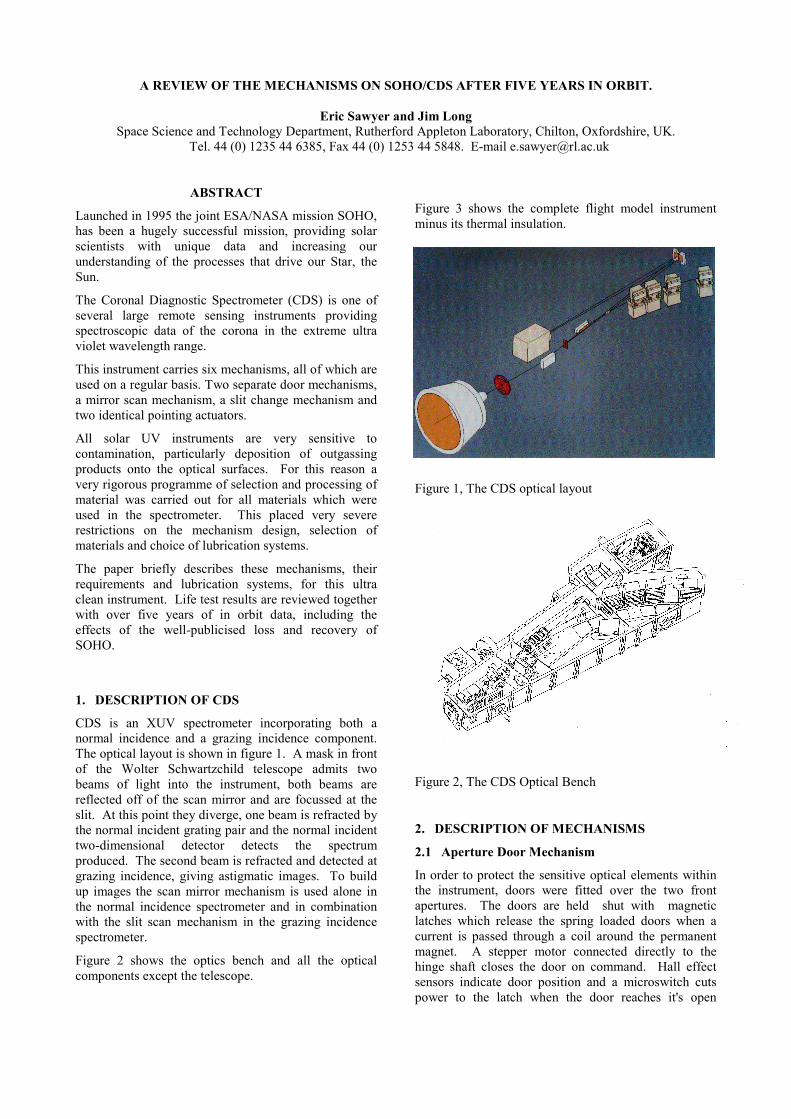
Figure 2 shows the optics bench and all the opticalcomponents except the telescope.
Figure 3 shows the complete flight model instrumentminus its thermal insulation.
Figure 1, The CDS optical layout
Figure 2, The CDS Optical Bench
2. DESCRIPTION OF MECHANISMS
2.1 Aperture Door Mechanism
In order to protect the sensitive optical elements withinthe instrument, doors were fitted over the two frontapertures. The doors are held shut with magneticlatches which release the spring loaded doors when acurrent is passed through a coil around the permanentmagnet. A stepper motor connected directly to thehinge shaft closes the door on command. Hall effectsensors indicate door position and a microswitch cutspower to the latch when the door reaches it's open

condition. Figure four shows one of the engineeringmodel door assemblies.
Figure 3, The CDS Flight model
Figure 4, An engineering model door assembly
2.2 Scan Mirror Mechanism
In order to build up two-dimensional images when usingthe normal incidence spectrometer, the image of the sunis scanned across the slit in two arc-second steps. Theflat mirror is held in an aluminium alloy mount, whichin turn is held in a pair of flex pivots. A lever protrudesfrom the back of the mirror mount through the wall ofthe spectrometer and is moved by the same steppermotor and ball screw arrangement as used in the slitmechanism. Figure 5 shows the engineering model scanmirror assembly, and figure 6 shows the mirrorassembly and the drive mechanism mounted on a testrig.
Figure 5, An engineering model scan mirror in itshousing
Figure 6, A scan mirror mechanism assembly
2.3 Slit Scan/Slit Change Mechanism
The normal incidence spectrometer uses a long slit andthe grazing incidence spectrometer uses a pinhole.Consequently, a mechanism is required to change fromone to the other. In addition, the grazing incidencespectrometer requires that the pinhole is rastered incombination with the scan mirror to enable two-dimensional images to be constructed.
Three long slits and three pinholes of various sizes arearranged in a line and attached to a carriage supportedon a linear slideway. This carriage is driven by astepper motor and recirculating ball screw. An absolutesingle turn optical encoder is attached to the back of themotor to give fine position indication. A linear encoderconsisting of an array of LEDs and photo diodes with amoving coded mask indicates which slit is in the focalplane.
The recirculating ball screw and linear slideways werelubricated with ion sputtered lead film.

An individual slit can be moved in increments of 2 arcseconds which is 25µm of linear movement. Figure 7shows the engineering model slit mechanism.
Figure 7, An engineering model slit mechanism
2.4 Offset Pointing Actuators.
The type of telescope used in CDS has a useful field ofview of about 4 arc minutes. The sun is 30 arc minuteswhen viewed from near the Earth. This requires that thewhole instrument is pointed to enable all areas of thesun to be viewed.
To achieve this, the interface between the instrumentstructure and the spacecraft consists of six pin jointedlegs. Four of these legs are of fixed length while therear two are linear actuators which allow the instrumentto move through +/- 0.75 degrees.
The linear actuators consist of a 200-step, size 23,hollow shaft stepper motor driving a plain screw and nutassembly of 1mm pitch.. A plain nut and screw waschosen because it is compact enough to fit inside arelatively small motor and is of sufficient load carryingcapacity carry a load of 3KN during launch. Also theefficiency is low enough to prevent back driving underload. Position readout is provided by a hybrid trackpotentiometer. Braycote 601 was chosen for lubricationas the body of the actuator virtually seals the device that
is well away from all optical components. Figure 8shows a flight model linear actuator
Figure 8, A flight model linear actuator
3. CLEANLINESS ISSUES
Solar viewing extreme ultra violet instruments areparticularly sensitive to molecular contamination, whichwhen exposed to unfiltered sunlight, rapidly turns blackand severely reduces the optical properties.
To counteract this threat, the instrument was designedwith cleanliness in mind. All sensitive items werecontained within the optics cavity from which allpotential sources of contamination were excluded. Thispresented many challenges for the designers of themechanisms, particularly the scan mirror drive and slitmechanisms. These two mechanisms were designedsuch that only the essential parts were within the opticscavity and all potentially dirty parts for example thestepper motors were out side the cavity. Thiscleanliness requirement also led to the choice of lead forthe lubricant.
4. PROBLEMS DURING DEVELOPMENT
As with all development programmes, problems wereencountered along the way.
4.1 Ball screw lubrication
High precision commercial units were selected mainlydue the availability of the size required. As previouslystated lead film lubrication was chosen, but obtainingsmooth torque characteristics after coating proved to bedifficult. The problems were tracked down to smallparticles of debris jamming the device. A specialprocedure was established which involved completestrip down of the unit, then coating the screw followedby precision cleaning and assembly at RAL. Smoothperformance was then achieved.
4.2 Vibration resistance
The scan mirror is supported by flex pivots, which needto be compliant to reduce the torque requirement, butstiff enough to resist vibration forces. The initial sizechosen failed in early vibration tests carried out on aprototype model. A stiffer pivot could not be used socollars and washers were incorporated to offload theforces on the pivot blades.

4.3 Step accuracy
To simplify the design of both the slit and mirrormechanisms, a one step per increment concept wasused. This relied on the accuracy of the stepper motorbeing better than 10% of a step size per step. Moststeppers only achieve about 20% step accuracy. Weworked closely with the manufacturer who made highaccuracy laminations and developed a special assemblytechnique to achieve the accuracy required.
4.4 Pointing system
As previously stated the instrument is required to pointthrough 3/4 of a degree in two axes and be isostaticallymounted to the spacecraft. Many schemes wereinvestigated in order to achieve these requirements butmost had the effect of considerably reducing the firstnatural frequency of the structure compared with itsfrequency in the free free condition.
To overcome this frequency limitation it was essentialto support the instrument at the points of inflection of itsfirst natural resonance. These positions were calculatedand the design modified to incorporate strong points atthese locations.
A method now had to be devised which allowedpointing and supported the instrument at these locations.The solution adopted consisted of six links withhemispherical bearings at each end. Two vertical linkswere positioned at the front, a second set of angled linkswere positioned such that a virtual pivot point wasformed on the centre line of the instrument, verticallyabove the front pair of links. The remaining two linkswere positioned to the rear and were inclined to the sideframes at 45º. This arrangement formed an isostaticmounting and supported the structure at its points ofinflection. Linear actuators to allow the instrument topoint through a small angle in two axes replaced the tworear struts.
Modal analysis and vibration testing of the structuralmodel indicated natural frequencies much lower thancalculated. It was discovered that the hemisphericalrose joints exhibited much lower dynamic stiffness thanexpected. Consequently to keep the natural frequencyhigh, the joints on the central legs were replaced by aflexure design.
The links and actuators can be seen in figure 3
5. LIFE TEST RESULTS
The duty cycle of all the mechanisms is fairly slow, sothe total number of operations is relatively small for theplanned mission life of 2 years with a possible extensionto 5 years.
Each type of mechanism was life tested in vacuum for aduration estimated using a mission duration of 12 yearsto incorporate a comfortable margin.
The only problem encountered was with the hybridtrack potentiometer in the linear actuators. We weretrying to run these unlubricated, but early failures invacuum resulted. Subsequently Braycote 601 wasapplied to the tracks that resulted in acceptable lifeperformance.
6. IN ORBIT PERFORMANCE
Soho was launched in December 1995 and apart fromone short period, the CDS instrument has been workingcontinuously.
The table below shows the accumulated running and lifetest duration for each mechanism.
In orbit Life test
Slit 4.8 million steps 5 million steps
Mirror 9 million steps 200 million steps
Pointingsystem
6.3 million steps 86 million steps
Door 50 operations No life test
As can be seen above the slit mechanism is getting closeto the life test duration but the design is very similar tothe mirror mechanism that was tested to a far greaterduration.
The pointing system has been used for less than 10% ofits life test duration.
All mechanisms are performing nominally, showing nosigns of degradation.
6.1 Door debris
The Sun facing surface of CDS is covered by a thickMLI blanket with an outer layer of ITO coated Kapton.
The aperture doors were not equipped with positivestops but rely on the MLI to arrest their opening. Thisworked well in test with a relatively gentle stoppingaction.
However, when in orbit one of the other instrumentsoperating in the visible, detected bright points shortlyafter the CDS doors were opened. This was eventuallytraced to small particles released by the CDS door,probably the ITO coating, scattering sun light. Thisappears to be only a transient phenomenon, with nopermanent effect.
6.2 Ageing
It is difficult to use in orbit data to assess theperformance of the mechanisms after nearly six years inorbit. There is no evidence to suggest that there hasbeen any significant degradation.

6.3 In orbit maintenance
With the lead film lubricated ball screws, so calledlubrication sequences are routinely carried out. Theseare designed to prevent build up of any debris fromaccumulating at the end of the normally used portion.The sequence consists of driving the ball screws pastthere normal operating range. This is carried outapproximately once per month.
7. SOHO LOSS AND RECOVERY
After about one and a half years in orbit, groundcontrollers lost contact with the spacecraft. Due to aseries of errors during a routine orbit manoeuvre, sunpointing was lost and the satellite defaulted to anemergency mode and should have recovered pointing.It did not and spent several months tumbling out ofcontrol before the ground team managed to recover it.
During this time out of contact all non-essentialservices, including the instruments were powered off.With sun pointing lost, the instrument's thermal controlsystems could not cope and all instruments sufferedlong periods with temperatures well outside those seenduring qualification testing.
In the case of CDS, the first telemetry back after therecovery indicated that the instrument has been to atemperature of at least 100ºC for a considerable periodof time. Due to the way SOHO had been tumbling, CDSwas on the side of the spacecraft continuously exposedto the sun. Radiating surfaces that were designed todissipated heat from the sun were now absorbing itdirectly, leading to very high local temperatures.
Nevertheless, All systems seemed to be working when itwas recovered and have been performing faultlessly forthe three years following the incident.