Embed Size (px)
Citation preview
i
A REVIEW OF SEABED AND PLACER MINING DEPOSITS IN INDIA
A THESIS SUBMITTED IN PARTIAL FULFILLMENT OF THE
REQUIREMENTS FOR THE DEGREE
Of
BACHELOR OF TECHNOLOGY
IN
MINING ENGINEERING
BY
ABHINEET KUMAR
Roll No: 107MN009
Department of Mining Engineering
National Institute of Technology, Rourkela
May, 2011
ii
A REVIEW OF SEABED AND PLACER MINING DEPOSITS IN INDIA
A THESIS SUBMITTED IN PARTIAL FULFILLMENT OF THE
REQUIREMENTS FOR THE DEGREE
Of
BACHELOR OF TECHNOLOGY
IN
MINING ENGINEERING
BY
ABHINEET KUMAR
Roll No: 107MN009
Under the guidance of
Prof. H.K.NAIK
Department of Mining Engineering
National Institute of Technology, Rourkela
May, 2011
iii
DEPARTMENT OF MINING ENGINEERING
NATIONAL INSTITUTE OF TECHNOLOGY,
ROURKELA-769008
CERTIFICATE
This is to certify that the thesis entitled “A Review of Sea-bed and Placer
Mining Deposits in India” submitted by Mr. Abhineet Kumar in partial
fulfillment of the requirements for the award of Bachelor of Technology
degree in Mining Engineering at National Institute of Technology,
Rourkela(Deemed University) is an authentic work carried out by him under
my supervision and guidance.
To the best of my knowledge, the matter embodied in the thesis has not been
submitted to any other University/Institute for the award of any Degree or
Diploma.
PROF. H. K. NAIK
Project Guide & Associate Professsor
Department of Mining Engineering
National Institute of Technology
Rourkela, Orissa-769008
Date:
iv
ABSTRACT
India, gifted with a coastline of over 6000 km, hosts some of the largest and richest shoreline
placers. The beach and dune sands in India contain heavy minerals like ilmenite, rutile, garnet,
zircon, monazite and sillimanite. A combination of favorable factors like network of drainage,
aided by wind and coastal processes like waves and currents, have influenced the formation of the
beach and adjoining dune sands.
Ilmenite-rich major beach and dune sand deposits occur in the coastal stretches of Kerala
(Chavara), Tamil Nadu (Manavala kurichi, Midalam, Vayakallur), Andhra Pradesh, Orissa and
Maharashtra. The Indian ilmenite commonly contains 50-60% TiO2 and is suitable for various
process technologies. Zircon, monazite and Sillimanite are ubiquitous in both the beach and inland
red Teri sands, and constitute potential co-products. The Indian resources of placer minerals are:
348 Million tons (Mt) of Ilmenite, 107 Mt of garnet, 21 Mt of zircon, 18 Mt of monazite and 130
Mt of Sillimanite. Indian resources constitute about 35% of world resources of Ilmenite, 10% of
Rutile, 14% of Zircon and 71.4% of Monazite. India meets about 10% of the world requirement of
garnet. This unique status is largely due to the exploratory efforts of the Atomic Minerals
Directorate for Exploration and Research (AMD) of the Department of Atomic Energy,
Government of India since 1950s.
v
ACKNOWLEDGEMENT
I wish to express my unfathomed gratitude and indebtedness to Prof. H.K.Naik
(Project Guide & Associate Professor), Department of Mining Engineering, NIT
Rourkela for entrusting this review topic with me and for his ever-helpful guidance,
assistive critical appraisal and tutelage during the project work.
I am thankful to DGM (Safety & Training), IRE Limited (OSCOM) Chatrapur,
Orissa for allowing me to visit the mining and processing areas at a very short
notice and providing logistic support. I am thankful to Mr. J.N. Sadangi (Senior
Manager, Mining), Mr.Beura (Senior Mining Manager, Training, and Mr.
G.K.Nayak (Manager, Mining) for assistance in the visit to IRE Ltd.
I would also like to thank sincerely Mr. Pramod Kumar( Manager, Mining) for his
guided tour around the mining area at IRE Ltd, Chatrapur and providing an insight
into the pros and cons of the industry.
I would like to thank National Institute of Oceanography, Goa for their assistance in
providing study literature on request.
ABHINEET KUMAR
107MN009, VIII Semester
Department of Mining Engineering
NIT Rourkela-769008
Date:
vi
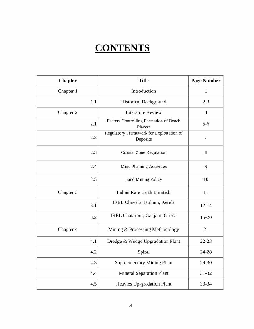
CONTENTS
Chapter Title Page Number
Chapter 1 Introduction 1
1.1 Historical Background 2-3
Chapter 2 Literature Review 4
2.1 Factors Controlling Formation of Beach
Placers 5-6
2.2 Regulatory Framework for Exploitation of
Deposits
7
2.3 Coastal Zone Regulation 8
2.4 Mine Planning Activities 9
2.5 Sand Mining Policy 10
Chapter 3 Indian Rare Earth Limited: 11
3.1 IREL Chavara, Kollam, Kerela
12-14
3.2 IREL Chatarpur, Ganjam, Orissa
15-20
Chapter 4 Mining & Processing Methodology 21
4.1 Dredge & Wedge Upgradation Plant 22-23
4.2 Spiral 24-28
4.3 Supplementary Mining Plant 29-30
4.4 Mineral Separation Plant 31-32
4.5 Heavies Up-gradation Plant 33-34
vii
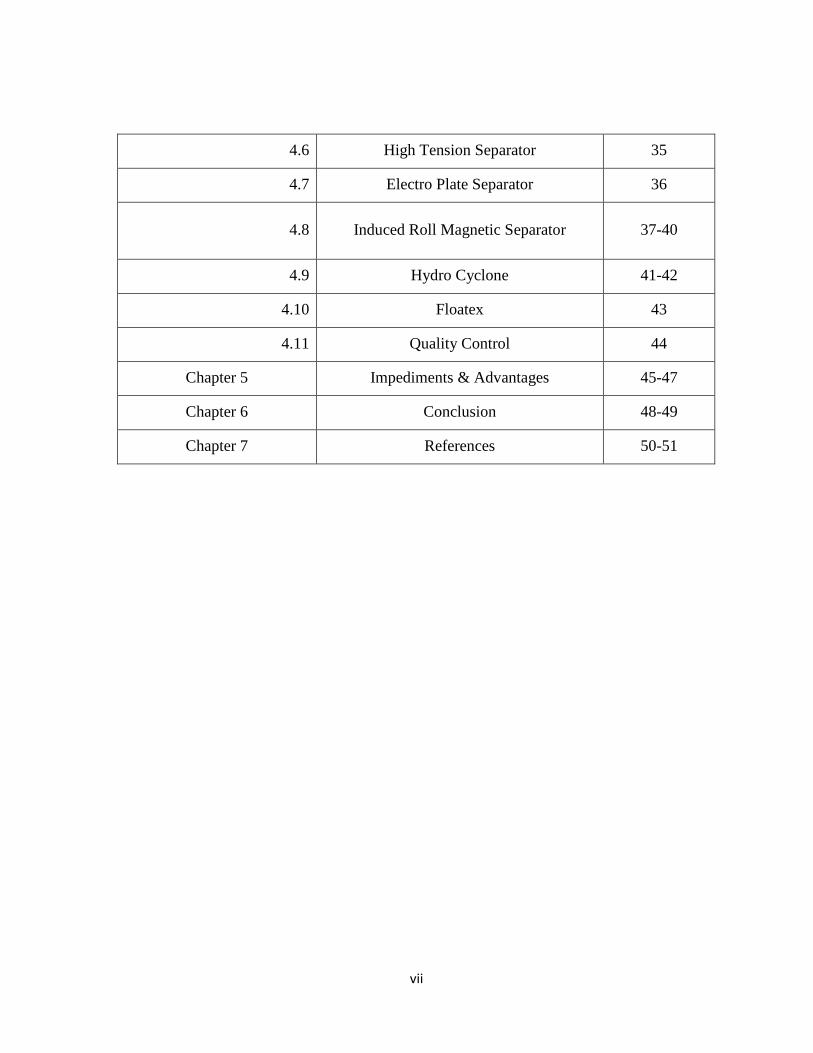
4.6 High Tension Separator 35
4.7 Electro Plate Separator 36
4.8 Induced Roll Magnetic Separator 37-40
4.9 Hydro Cyclone 41-42
4.10 Floatex 43
4.11 Quality Control 44
Chapter 5 Impediments & Advantages 45-47
Chapter 6 Conclusion 48-49
Chapter 7 References 50-51
viii
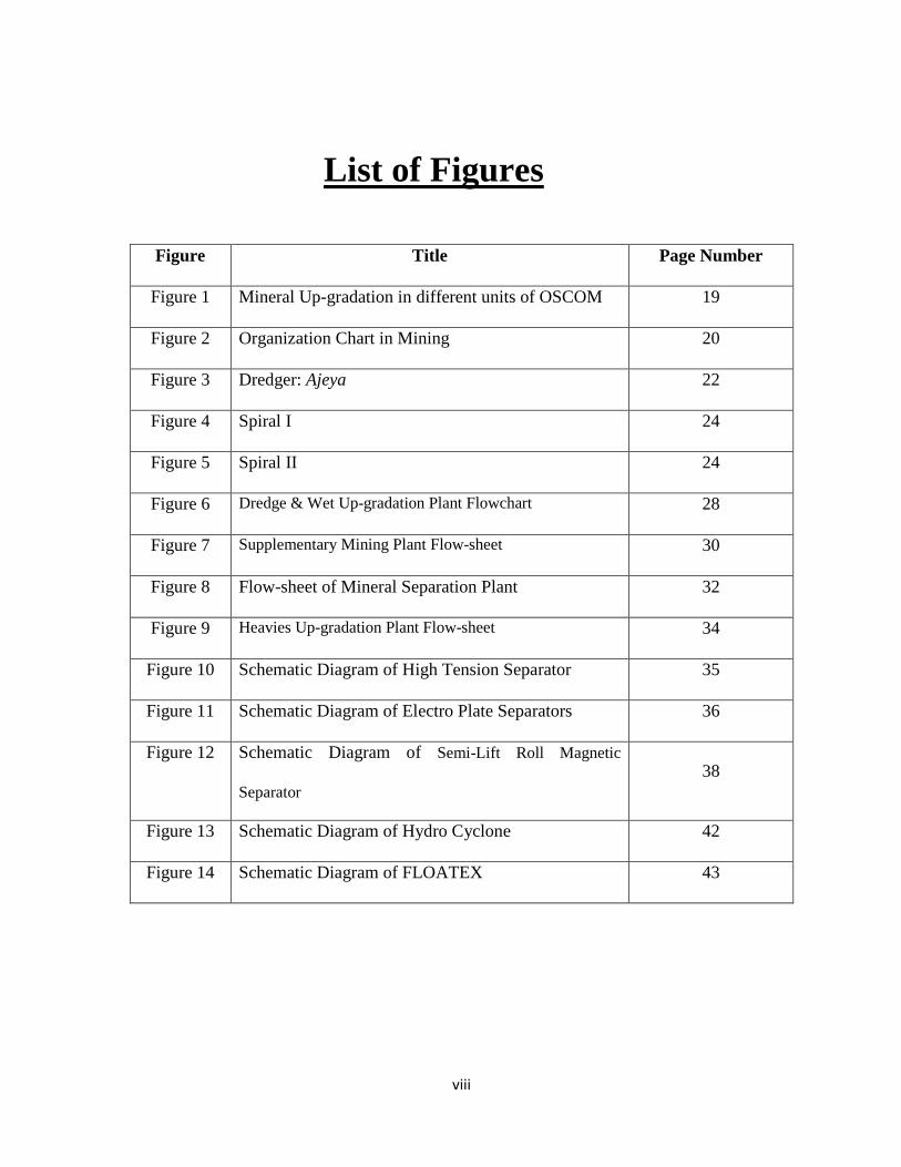
List of Figures
Figure Title Page Number
Figure 1 Mineral Up-gradation in different units of OSCOM 19
Figure 2 Organization Chart in Mining 20
Figure 3 Dredger: Ajeya 22
Figure 4 Spiral I 24
Figure 5 Spiral II 24
Figure 6 Dredge & Wet Up-gradation Plant Flowchart 28
Figure 7 Supplementary Mining Plant Flow-sheet 30
Figure 8 Flow-sheet of Mineral Separation Plant 32
Figure 9 Heavies Up-gradation Plant Flow-sheet 34
Figure 10 Schematic Diagram of High Tension Separator 35
Figure 11 Schematic Diagram of Electro Plate Separators 36
Figure 12 Schematic Diagram of Semi-Lift Roll Magnetic
Separator 38
Figure 13 Schematic Diagram of Hydro Cyclone 42
Figure 14 Schematic Diagram of FLOATEX 43
ix
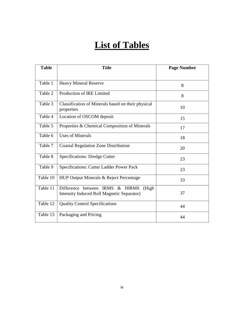
List of Tables
Table Title Page Number
Table 1 Heavy Mineral Reserve 8
Table 2 Production of IRE Limited 8
Table 3 Classification of Minerals based on their physical properties 10
Table 4 Location of OSCOM deposit 15
Table 5 Properties & Chemical Composition of Minerals 17
Table 6 Uses of Minerals 18
Table 7 Coastal Regulation Zone Distribution 20
Table 8 Specifications: Dredge Cutter 23
Table 9 Specifications: Cutter Ladder Power Pack 23
Table 10 HUP Output Minerals & Reject Percentage 33
Table 11 Difference between IRMS & HIRMS (High Intensity Induced Roll Magnetic Separator)
37
Table 12 Quality Control Specifications 44
Table 13 Packaging and Pricing 44
1
Chapter 1
INTRODUCTION
2
Historical Background
The initial discovery of the rare mineral deposit in India was on the western coast. In the year 1909,
the presence of the mineral monazite was observed in coir, a coconut fiber, shipped to Germany
from India. He traced back to the place from where the coir was exported and this lead to the
discovery of the placer deposits of these minerals on the western coast of India, in the erstwhile
princely state of Travancore. As thorium nitrate, a chemical produced from the mineral monazite
was in good demand at that time for the production of mantles for gas lights, efforts started
immediately for recovery of monazite from this deposit. Even though with the advent of electricity,
the demand for gas lights and ion turn that for thorium nitrate diminished, interest in these deposits
continued since by that time technology developed for the production of titanium dioxide from the
mineral Ilmenite. During the period 1930 to 1955 a number of foreign and Indian owned
companies operated in the then princely state of Travancore for the production of the mineral
Ilmenite from these deposits. However, during the period 1955-1960 all these companies were
closed down due to market and management problems.
The Atomic Energy Commission was set up by the Government of India in the year 1948. Indian
Rare Earths Limited (IREL) was incorporated in 1951 as a fully owned central Government
undertaking under the Department of Atomic Energy. IREL initially was entrusted with acquiring
the technology for the production of rare earths compounds from the mineral monazite. As the
beach sand mineral operation came to stoppage from the 1960s, IREL at the instance of the central
government decided to take over the beach sand mineral beneficiation also. Accordingly IREL took
over the assets of the closed mineral operation companies at Chavara and Manavalakurichy.
Manavalakurichy plant came into operation in 1968 and the Chavara plant in 1970. After a gap of
20 years, IREL commissioned its largest Division called Orissa Sand Complex (OSCOM) at
3
Chatrapur, Orissa. Today IREL operates these four units and produces/sells six heavy minerals
namely ilmenite, rutile, zircon, monazite, sillimanite and garnet as well as various value added
products.
Under the Indian Companies Act, 1913, Indian Rare Earths Limited was incorporated in 1950 as a
private company as a joint venture with the then Government of Travancore, Cochin. In 1963,
IREL became a full-fledged Govt. undertaking under DAE. In 1952, production commenced at
RED, which was dedicated to the nation by Sri Jawaharlal Nehru. OSCOM was set up during 1972,
construction had been started in 1975 and mining had been started in 1984.
Main objective of IREL is to emerge as a leading player in the area of mining and
separation of beach sand deposits to produce minerals as well as process value added products. It
has mineral processing plants at Orissa, Tamilnadu & Kerala, Rare Earths division at Alwaye,
Kerala and Research center at Kollam, Kerala. Its registered and corporate offices are in Mumbai,
Maharashtra.
4
Chapter 2
LITERATURE REVIEW
5
FACTORS CONTROLLING FORMATION OF BEACH PLACERS
Some of the geological and geomorphological factors that control the concentration of heavy
minerals along the Indian coast are as follows:
� Geological control: The physico-chemical behaviour of provenance rocks, i.e., igneous,
metamorphic or sedimentary and the effect of various geological processes have played a
vital role in contributing sediments to form a placer deposit.
� Climatic Factor: The climate of the region has a great role to play in decomposing and
disintegrating the rock and mineral fragments that get liberated and concentrated. Tropical
to sub-tropical climate promotes deep chemical weathering along coastal region. These
conditions also favoured the formation of laterites that, in effect, is a process of pre-
concentration.
� Drainage Pattern: The availability of young and youthful rivers and their high density,
coupled with climatic factors, played a prominent role in the supply of material for
concentration along favourable locales, especially along the Ghat section of Kerala and
Tamil Nadu coasts. The rivers joining the Bay of Bengal on the east coast, however, have
attained maturity and in many cases delta systems have developed; e.g. Mahanadi,
Godavari, Krishna, Cauvery etc.
� Coastal Processes: Wave velocity, long shore currents and wind speed also have their
effects in littoral transport, sorting and deposition of placer minerals. Emergence and
submergence of the coast during geological past also affected the beach placer formation.
Apart from these, numerous other factors that helped in the formation of these deposits are coastal
geomorphology, neo-tectonics and continental shelf morphology.
6
The origin of the Chavara deposits belong to the parent rock types available in the Western Ghat
Mountain ranges which contain these minerals in very low concentration to call for profitable
extraction. The main source rocks are Khondalites, Chamockites, Gneiss, Granites, Laterites and
Sandstones etc.
The actual sorting and concentration takes place due to the actions of two principal agents i.e.
action waves and surfs and the action of the wind. Ocean waves and surfs play predominant role in
the concentration of the heavy minerals. A breaking wave takes all the foreshore minerals to the
beach but the backwash carries only the lighter minerals back to the sea. Repeated action of waves
results in sorting and the concentration of heavy minerals in beach placer deposit. After the
concentration is over, action of the wind further enriches the concentration by blowing away the
finer and the lighter sand particles, thus leaving the in-situ deposit rich in heavy minerals.
7
REGULATORY FRAMEWORK FOR EXPLOITATION OF DEPOSITS
The exploitation of beach sand deposits and separation of heavy minerals are guided under various
regulatory framework and statutory provisions as follows:
� The minerals occur in the placer deposits and mined for further beneficiation and
separation of its constituent minerals. Hence Mines Act 1952, Metalliferous Minerals
Regulation 1961, Mines & Minerals (Development & Regulation) Act 1957, Mineral
Concession Rules 1960, Mineral Conservation Development Rules 1988 etc. are
applicable.
� Ilmenite, rutile, zircon, monazite & leucoxene (brown ilmenite) are defined as ‘Prescribed
Substances’ under Atomic Energy Act, 1962. Necessary license and approvals are to be
obtained from DAE before proceeding with the installations and operation of mining and
mineral separation plant.
� Monazite is one of the constituent minerals in the beach sand placer deposit, which
constitutes thorium and uranium and has a potential use for nuclear application. The beach
placer deposits are located within 500 m from the high tide line (HTL) of the sea shore and
covered under the Coastal Regulatory Zone (CRZ). Under the notification, the
entrepreneurs have to obtain No Objection Certificate (NOC) from the State Pollution
Control Board, Dept. of Environment of the State Govt. and also from MoEF, Govt. of
India prior to the installation of plants within CRZ.
8
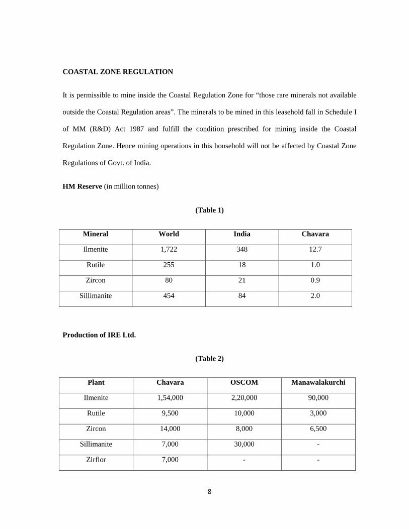
COASTAL ZONE REGULATION
It is permissible to mine inside the Coastal Regulation Zone for “those rare minerals not available
outside the Coastal Regulation areas”. The minerals to be mined in this leasehold fall in Schedule I
of MM (R&D) Act 1987 and fulfill the condition prescribed for mining inside the Coastal
Regulation Zone. Hence mining operations in this household will not be affected by Coastal Zone
Regulations of Govt. of India.
HM Reserve (in million tonnes)
(Table 1)
Mineral World India Chavara
Ilmenite 1,722 348 12.7
Rutile 255 18 1.0
Zircon 80 21 0.9
Sillimanite 454 84 2.0
Production of IRE Ltd.
(Table 2)
Plant Chavara OSCOM Manawalakurchi
Ilmenite 1,54,000 2,20,000 90,000
Rutile 9,500 10,000 3,000
Zircon 14,000 8,000 6,500
Sillimanite 7,000 30,000 -
Zirflor 7,000 - -
9
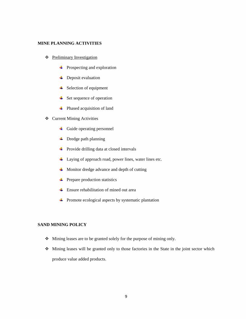
MINE PLANNING ACTIVITIES
� Preliminary Investigation
Prospecting and exploration
Deposit evaluation
Selection of equipment
Set sequence of operation
Phased acquisition of land
� Current Mining Activities
Guide operating personnel
Dredge path planning
Provide drilling data at closed intervals
Laying of approach road, power lines, water lines etc.
Monitor dredge advance and depth of cutting
Prepare production statistics
Ensure rehabilitation of mined out area
Promote ecological aspects by systematic plantation
SAND MINING POLICY
� Mining leases are to be granted solely for the purpose of mining only.
� Mining leases will be granted only to those factories in the State in the joint sector which
produce value added products.
10
� Proposals for establishing such factories as mentioned above shall be examined first by the
Kerala State Industrial Development Corporation before placing it before the Council of
Ministers for consideration.
� A study will be conducted by the Department of Mining and Geology and the Centre for
Earth Science Studies jointly as to the quantum of mineral sand which could be mined in
the area, and a report given to the Government.
� A notification under the relevant statute will be issued prohibiting all future uses of lands
bearing the mineral sand, for other purposes.
� Action will be taken to request Govt. of India for increasing the present loyalty of mineral
sand.
� The eight blocks in the Chavara Barrier Beach area, at present earmarked for Kerala
Minerals and Metals Limited and the Indian Rare Earths will not be leased out to any other
applicants.
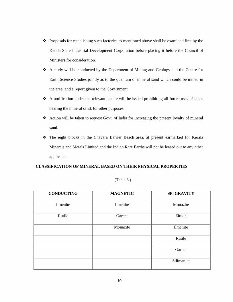
CLASSIFICATION OF MINERAL BASED ON THEIR PHYSICAL P ROPERTIES
(Table 3 )
CONDUCTING MAGNETIC SP. GRAVITY
Ilmenite Ilmenite Monazite
Rutile Garnet Zircon
Monazite Ilmenite
Rutile
Garnet
Silimanite
11
Chapter 3
INDIAN RARE EARTH LIMITED
� CHAVARA
� CHATARPUR
12
IREL Chavara, Kollam, Kerela
INTRODUCTION
LOCATION:
The Chavara plant is located at about 19 km from the proposed area and 1.5 km from the NH 47,
Kanyakumari- Salem Highway, and this is at 13 km from the district headquarters at Kollam and
80 km from the capital city, Trivandrum. It has all the infrastructural facilities for operating the
mines and processing plant. Export of the minerals is through Neendakara Port, which is about 5
km from the plant & Cochin Port which is 130 km to the North of the IRE plant.
Production Capacity
The present production capacity of Chavara unit stands at 154000 tonnes of ilmenite, 9500 tonnes
of rutile, 14000 tonnes of zircon and 7000 tonnes of sillimanite. In addition the plant has facilities
for annual production of ground zircon (-45 micron). With a sales turnover of approx. Rs 105
crores and foreign exchange earning of over Rs 39 crores, this plant caters to the requirement of a
host of advanced markets viz. USA, Japan & many others in addition to meeting the needs of
domestic markets.
Certification
IRE Ltd., Chavara was certified to ISO 9002:1994 in September 2000. Subsequently the QMS
system is upgraded to ISO 9001:2000 in March 2004. The company is also certified to ISO
14001:1996 in March 2004 which was upgraded to ISO 14001:2004 in June 2006. Later all
systems were integrated and this integrated system was certified to OHSAS 18001:1997.
13
GEOLOGY OF DEPOSIT
Chavara deposit is rated as one of the best of its kind in the world owing to its unique mineralogical
assemblage, vast reserves and chemical characters of ilmenite with 60% TiO2. The Chavara beach
deposit covers a coastal length of 22.54 km and width of 225 m occurring between the two tidal
channels at Neendakara in the south and Kayamkulam in the north in Kollam district. The coastal
strip from Neendakara to Kayamkulam was divided into 8 blocks for sanctioning mining lease.
This leasehold falls to the east of Block II (IRE Block I) and that block forms western boundary of
this plot. The coastal deposits are placer deposits formed between the two tidal channels. The
barrier beach placer is under active exploitation by Indian Rare Earths Ltd. The area had been
under intensive mining for the past 6 decades. Private parties carried out the mining operations in
this area even before the formation of Indian Rare Earths Ltd. The total area of the barrier beach is
4.2 sq. km with an average THM content of 49.08%. The deposit has a thickness of 7.62 m and the
grade gradually depletes with depth. The collection of seasonal washings of 35% grade which
accumulate during southwest monsoon is also being carried out wherever the seawalls are non-
existent. The Neendakara-Kayamkulam Eastern Extension between the T.S. Canal and one
kilometer to the east over an area of 19.22 sq. km records THM grade of the order of 10.05%. The
heavy mineral concentration depletes gradually due east. The Neendakara – Kayamkulam Eastern
Extension (Phase II) is the extension of phase I for 6 km inland or up to end of sand stretch. The
northern sector of phase II covers an area of 45.8 sq. km with an average THM grade of 7.41%.
The southern sector is spread over an area of 50.39 sq. km recording THM grade of 7.5%.
Extensive exploration has been carried out to the east of the Kayal (canal). The area, however, has
dense population and has created some social problems. Only the surface dunes have been
exploited leaving most of the deposit untouched.

14
It is proposed to mine the mineral sand of Vellanthuruthu Mining area by opencast method using a
cutter suction dredge floating on a set of pontoons. The dredge has a capacity of 120 tph and the
loosened material along with water is pumped to gravity concentrators to enrich the heavy minerals
up to 85%. The waste sand from the plant will be deposited on the rear end of the dredge pond for
back filling.
15
IREL Chatrapur, Ganjam, Orissa (OSCOM)
INTRODUCTION
LOCATION:
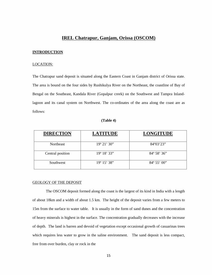
The Chatrapur sand deposit is situated along the Eastern Coast in Ganjam district of Orissa state.
The area is bound on the four sides by Rushikulya River on the Northeast, the coastline of Bay of
Bengal on the Southeast, Kandala River (Gopalpur creek) on the Southwest and Tampra Inland-
lagoon and its canal system on Northwest. The co-ordinates of the area along the coast are as
follows:
(Table 4)
DIRECTION LATITUDE LONGITUDE
Northeast 19º 21’ 30” 84º03’23”
Central position 19º 18’ 33” 84º 58’ 36”
Southwest 19º 15’ 38” 84º 55’ 00”
GEOLOGY OF THE DEPOSIT
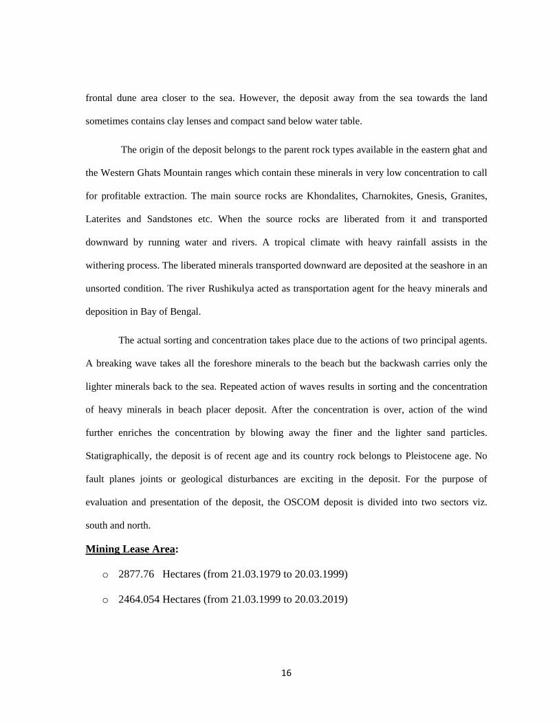
The OSCOM deposit formed along the coast is the largest of its kind in India with a length
of about 18km and a width of about 1.5 km. The height of the deposit varies from a few meters to
15m from the surface to water table. It is usually in the form of sand dunes and the concentration
of heavy minerals is highest in the surface. The concentration gradually decreases with the increase
of depth. The land is barren and devoid of vegetation except occasional growth of casuarinas trees
which requires less water to grow in the saline environment. The sand deposit is less compact,
free from over burden, clay or rock in the
16
frontal dune area closer to the sea. However, the deposit away from the sea towards the land
sometimes contains clay lenses and compact sand below water table.
The origin of the deposit belongs to the parent rock types available in the eastern ghat and
the Western Ghats Mountain ranges which contain these minerals in very low concentration to call
for profitable extraction. The main source rocks are Khondalites, Charnokites, Gnesis, Granites,
Laterites and Sandstones etc. When the source rocks are liberated from it and transported
downward by running water and rivers. A tropical climate with heavy rainfall assists in the
withering process. The liberated minerals transported downward are deposited at the seashore in an
unsorted condition. The river Rushikulya acted as transportation agent for the heavy minerals and
deposition in Bay of Bengal.
The actual sorting and concentration takes place due to the actions of two principal agents.
A breaking wave takes all the foreshore minerals to the beach but the backwash carries only the
lighter minerals back to the sea. Repeated action of waves results in sorting and the concentration
of heavy minerals in beach placer deposit. After the concentration is over, action of the wind
further enriches the concentration by blowing away the finer and the lighter sand particles.
Statigraphically, the deposit is of recent age and its country rock belongs to Pleistocene age. No
fault planes joints or geological disturbances are exciting in the deposit. For the purpose of
evaluation and presentation of the deposit, the OSCOM deposit is divided into two sectors viz.
south and north.
Mining Lease Area:
o 2877.76 Hectares (from 21.03.1979 to 20.03.1999)
o 2464.054 Hectares (from 21.03.1999 to 20.03.2019)
17
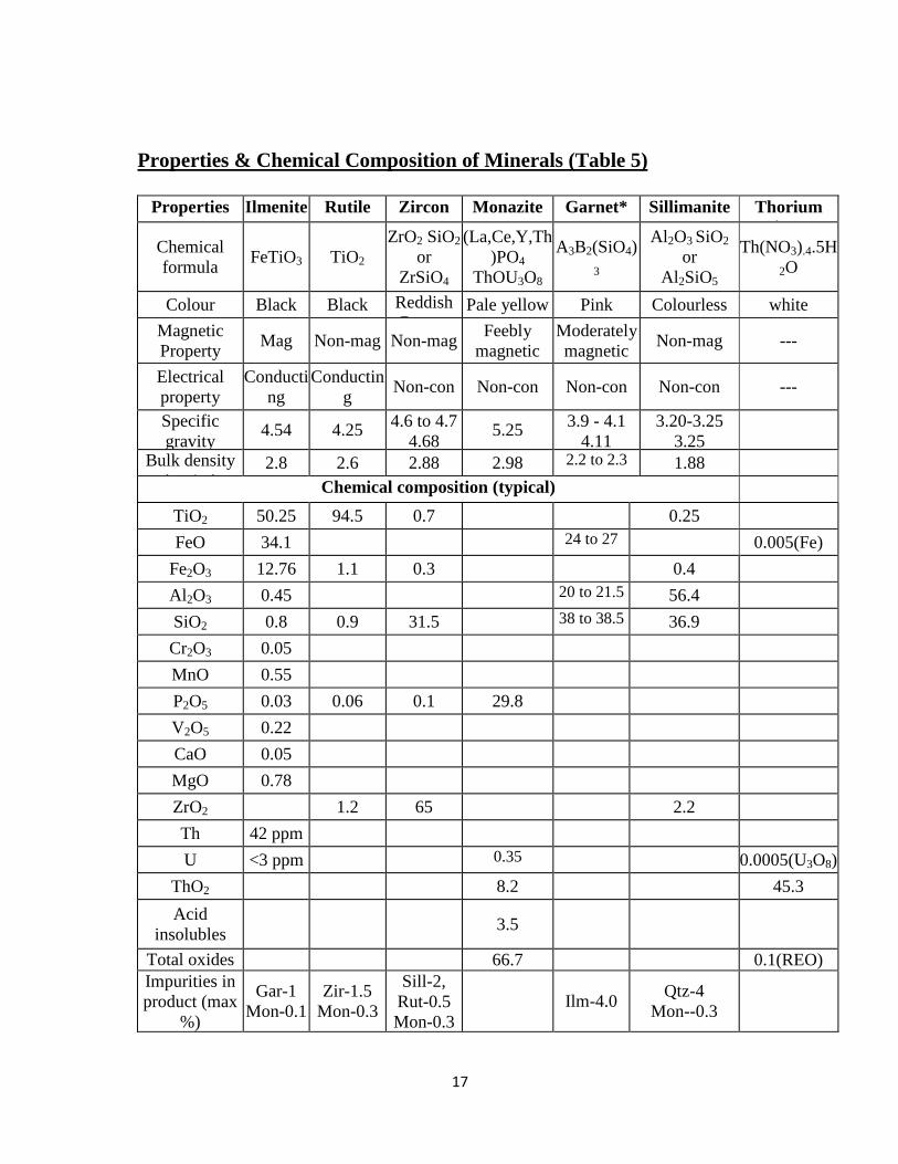
Properties & Chemical Composition of Minerals (Table 5)
Properties Ilmenite Rutile Zircon Monazite Garnet* Sillimanite Thorium Nitrate
Chemical formula
FeTiO3 TiO2 ZrO2 SiO2
or ZrSiO4
(La,Ce,Y,Th)PO4
ThOU3O8
A3B2(SiO4)3
Al 2O3 SiO2
or Al 2SiO5
Th(NO3).4.5H2O
Colour Black Black Reddish Brown
Pale yellow Pink Colourless white
Magnetic Property
Mag Non-mag Non-mag Feebly
magnetic Moderately magnetic
Non-mag ---
Electrical property
Conducting
Conducting
Non-con Non-con Non-con Non-con ---
Specific gravity
4.54 4.25 4.6 to 4.7 4.68
5.25 3.9 - 4.1 4.11
3.20-3.25 3.25
Bulk density (gm/cc)
2.8 2.6 2.88 2.98 2.2 to 2.3 1.88
Chemical composition (typical)
TiO2 50.25 94.5 0.7 0.25
FeO 34.1 24 to 27 0.005(Fe)
Fe2O3 12.76 1.1 0.3 0.4
Al 2O3 0.45 20 to 21.5 56.4
SiO2 0.8 0.9 31.5 38 to 38.5 36.9
Cr2O3 0.05
MnO 0.55
P2O5 0.03 0.06 0.1 29.8
V2O5 0.22
CaO 0.05
MgO 0.78
ZrO2 1.2 65 2.2
Th 42 ppm
U <3 ppm 0.35 0.0005(U3O8)
ThO2 8.2 45.3
Acid insolubles
3.5
Total oxides (REO+ThO)
66.7 0.1(REO) Impurities in product (max
%)
Gar-1 Mon-0.1
Zir-1.5 Mon-0.3
Sill-2, Rut-0.5 Mon-0.3
Ilm-4.0 Qtz-4
Mon--0.3
18
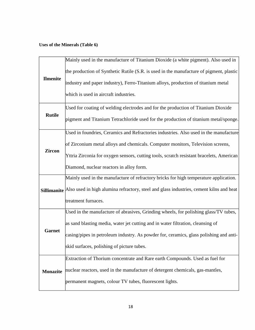
Uses of the Minerals (Table 6)
Ilmenite
Mainly used in the manufacture of Titanium Dioxide (a white pigment). Also used in
the production of Synthetic Rutile (S.R. is used in the manufacture of pigment, plastic
industry and paper industry), Ferro-Titanium alloys, production of titanium metal
which is used in aircraft industries.
Rutile
Used for coating of welding electrodes and for the production of Titanium Dioxide
pigment and Titanium Tetrachloride used for the production of titanium metal/sponge.
Zircon
Used in foundries, Ceramics and Refractories industries. Also used in the manufacture
of Zirconium metal alloys and chemicals. Computer monitors, Television screens,
Yttria Zirconia for oxygen sensors, cutting tools, scratch resistant bracelets, American
Diamond, nuclear reactors in alloy form.
Sillimanite
Mainly used in the manufacture of refractory bricks for high temperature application.
Also used in high alumina refractory, steel and glass industries, cement kilns and heat
treatment furnaces.
Garnet
Used in the manufacture of abrasives, Grinding wheels, for polishing glass/TV tubes,
as sand blasting media, water jet cutting and in water filtration, cleansing of
casing/pipes in petroleum industry. As powder for, ceramics, glass polishing and anti-
skid surfaces, polishing of picture tubes.
Monazite
Extraction of Thorium concentrate and Rare earth Compounds. Used as fuel for
nuclear reactors, used in the manufacture of detergent chemicals, gas-mantles,
permanent magnets, colour TV tubes, fluorescent lights.
19
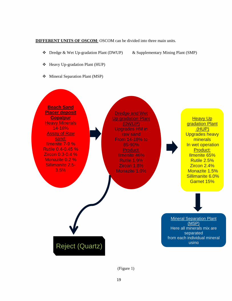
DIFFERENT UNITS OF OSCOM : OSCOM can be divided into three main units.
� Dredge & Wet Up-gradation Plant (DWUP) & Supplementary Mining Plant (SMP)
� Heavy Up-gradation Plant (HUP)
� Mineral Separation Plant (MSP)
(Figure 1)
Beach Sand Placer deposit
Gopalpur Heavy Minerals
14-18% Assay of Raw
sand: Ilmenite 7-9 %
Rutile 0.4-0.45 % Zircon 0.3-0.4 % Monazite 0.2 % Sillimanite 2.5-
3.5%
Dredge and Wet Up gradation Plant
(DWUP) Upgrades HM in
raw sand From 14-18% to
85-90% Product:
Ilmenite 46% Rutile 1.9% Zircon 1.8%
Monazite 1.0% Sillimanite 10%
Heavy Up gradation Plant
(HUP) Upgrades heavy
minerals In wet operation
Product: Ilmenite 65% Rutile 2.5% Zircon 2.4%
Monazite 1.5% Sillimanite 6.0%
Garnet 15%
Mineral Separation Plant (MSP)
Here all minerals mix are separated
from each individual mineral using
Reject (Quartz)
20
ACTS AND REGULATIONS
� Environmental Protection Act, 1986
� Coastal Regulation Zone (CRZ), February, 1991: It is measured 500 m from the
appropriate base line towards the land site and 200 m measured towards the sea from high
tide line.
(Table 7)
CRZ 1 Area which is ecologically sensitive (National Park)
CRZ 2 Prior to 1991, any build-up area around the sea shore
CRZ 3 Generally rural areas, beaches and relatively non-disturbing areas (OSCOM
is under CRZ 3)
CRZ 4 Coastal area of island (Andaman - Nicobar)
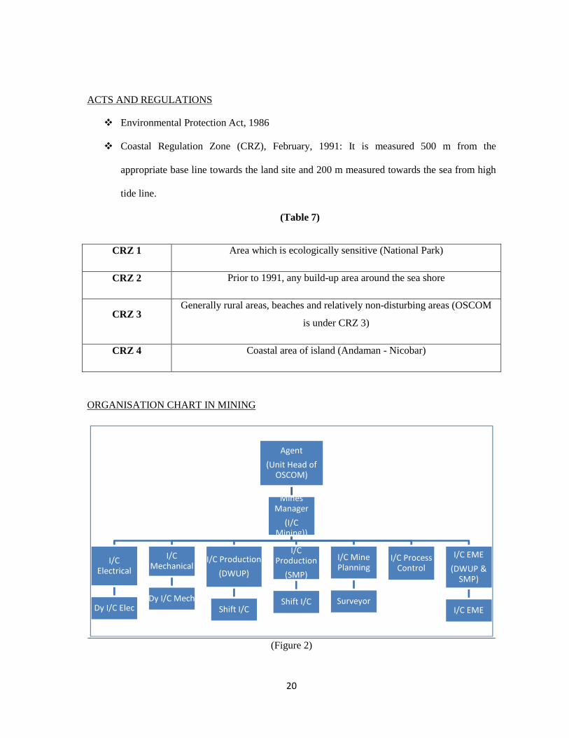
ORGANISATION CHART IN MINING
(Figure 2)
Agent
(Unit Head of OSCOM)
Mines Manager
(I/C Mining))
I/C Electrical
Dy I/C Elec
I/C Mechanical
Dy I/C Mech
I/C Production
(DWUP)
Shift I/C
I/C Production
(SMP)
Shift I/C
I/C Mine Planning
Surveyor
I/C Process Control
I/C EME
(DWUP & SMP)
I/C EME
21
Chapter 4
MINING & PROCESSING
METHODOLOGY
22
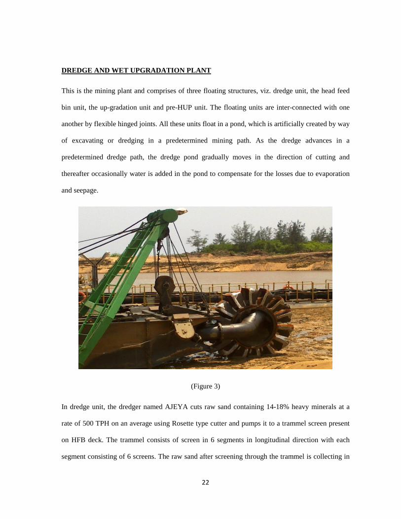
DREDGE AND WET UPGRADATION PLANT
This is the mining plant and comprises of three floating structures, viz. dredge unit, the head feed
bin unit, the up-gradation unit and pre-HUP unit. The floating units are inter-connected with one
another by flexible hinged joints. All these units float in a pond, which is artificially created by way
of excavating or dredging in a predetermined mining path. As the dredge advances in a
predetermined dredge path, the dredge pond gradually moves in the direction of cutting and
thereafter occasionally water is added in the pond to compensate for the losses due to evaporation
and seepage.
(Figure 3)
In dredge unit, the dredger named AJEYA cuts raw sand containing 14-18% heavy minerals at a
rate of 500 TPH on an average using Rosette type cutter and pumps it to a trammel screen present
on HFB deck. The trammel consists of screen in 6 segments in longitudinal direction with each
segment consisting of 6 screens. The raw sand after screening through the trammel is collecting in
23
the HFB, from where it is pumped to spirals for separation of HM. In spirals, the separation of HM
has been done from the rest of the sand by the combined action of centrifugal force, gravitational
force and drag force. A number of stage separations are necessary to obtain the desired grade of the
product with higher recovery of HM. The output of the plant varies from 86-90% HM. The tailings
generated are densified using hydro-cyclones and are pumped to the rear of the HFB deck for
backfilling of the mined out area. As the entire plant is a floating one, the shifting of the plant is
carried out using eight numbers of hydraulic winches present on the deck.
Dredge Cutter: (Table 8)
Cutter Ladder Power Pack: (Table 9)
Type Rosette type with 5 cutting vanes
Material Ni-hard chrome
Speed 0-34 RPM
Motor Capacity 75 KW
Cutting Torque 690 to 1835 kg-m
Capacity 75 KW, 415 Volts, 128 Amps
Pressure 250 bars
Speed 1475 RPM
Ladder Lift 6 m
24
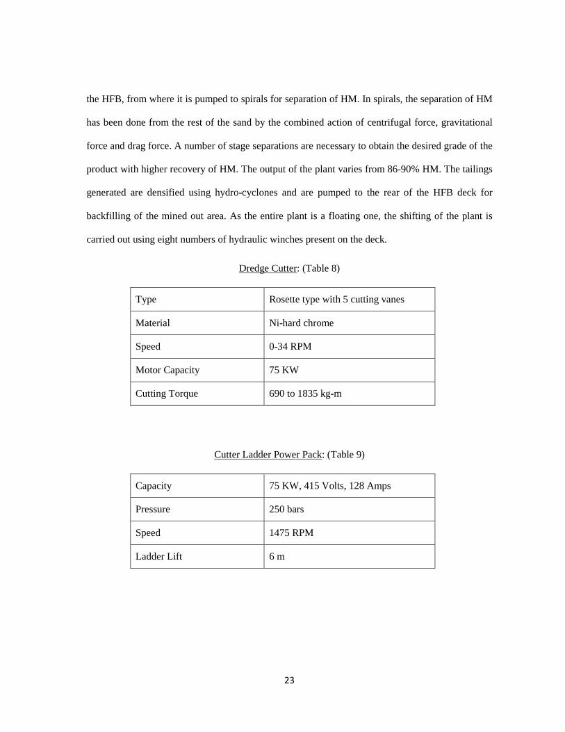
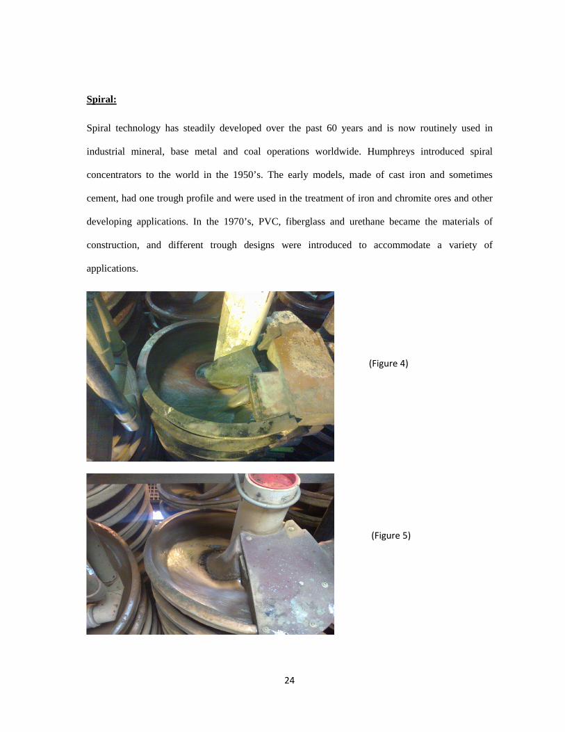
Spiral:
Spiral technology has steadily developed over the past 60 years and is now routinely used in
industrial mineral, base metal and coal operations worldwide. Humphreys introduced spiral
concentrators to the world in the 1950’s. The early models, made of cast iron and sometimes
cement, had one trough profile and were used in the treatment of iron and chromite ores and other
developing applications. In the 1970’s, PVC, fiberglass and urethane became the materials of
construction, and different trough designs were introduced to accommodate a variety of
applications.
(Figure 4)
(Figure 5)
25
Principle of operation:
In spirals, the separation of HM has been done from the rest of the sand by the combined
action of centrifugal force, gravitational force and drag force. The trough of the spiral is inclined
towards the centre. So, the heavier particles slide towards the centre quickly, as they fall from the
top. Due to the centrifugal force, the lighter particles move outside and heavier towards the centre.
The particles having high specific gravities move towards the centre of the spiral column and
subsequently tapped by means of splitters. Due to all above reasons, heavier particles move
towards centre and are collected as concentrate, whereas lighter particles are collected from the
outer portion of the spiral as tails with the help of splitter openings.
Operating parameters in Spirals:
� Feed Grade
� Feed Sizing
� Feed Rate
� Feed Pulp Density
� Splitter Position
� Diverter Position
26
Working Procedure
� Water operation procedure (process start up)
Open fully both R-1 and R-2 flood valves.
Set R-1 and R-2 density auto controllers to 1.25 to 1.45 SG or approximately 25 to 45%
solids w/w depending upon the feed grade condition.
Start trammel and fill surge bin with water using the dredge discharge.
Ensure the surge bin is level and overflowing in the correct areas.
Start R-1 and R-2 pumps and check T-1, T-2, T-3, cleaner, re-cleaner and output bin levels.
Start T-1 and T-2 tailings and check dewatering cyclone operation.
Start T-3, cleaner, output delivery pumps. Check ampere and pressure.
Ensure that T-3 flood valve is closed.
The plant should now be balanced and operative on water.
Before starting T-3 pump, the operator should ensure that neither the dozer nor any person
is present in the tails stacking area.
� Solis operation procedure (slurry feeding)
I. Surging operation
Operator must always run the head feed bin on surging condition. However in case of
practical difficulties, they should switch over to non-surging condition only with the
instruction of shift engineer.
Direct the dredge to start mining solids and fill the bin to a safe working level of approx.
70 cm.
27
Manually check the solids level of the surge bin with dip stick.
Check the surge bin barge trim and free board.
Close both flood off valves slowly by 5 turns.
Check density gauges for reaction and stability.
Close flood off valves a further 2.5turns and again check density gauges.
Check function and position of automatic control valves.
Ensure system is operating in correct range.
Gradually close the flood off valves and recheck controller position.
Both primary circuits should now be in the stable operation at 1.25 to 1.45 SG.
Check the dewatering cyclone under flows and the solids level in the T-3 bin.
Ensure the dredge operator maintains the surge bin solids within the predetermined range
(normally 70 to90 cm is a safe level).
Log any variation to stable operation with reason and action taken.
If the dredge cannot maintain the optimum surge bin operating level and it falls below
70cm, then revert back to water operation until sufficient solids are available.
If the dredge operator overfills the surge bin above 90 cm level, instruct him to operate on
water until the system is safely under control and surge bin level is corrected.
Do not operate the primary pumps at higher density than 1.45SG until the above operating
parameters are fully understood.
28
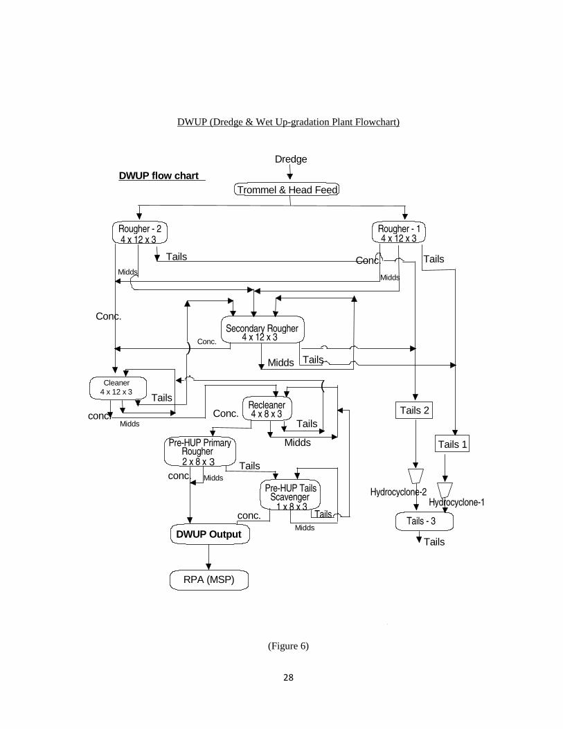
DWUP (Dredge & Wet Up-gradation Plant Flowchart)
Dredge
Trommel & Head Feed Bin
Rougher - 2 4 x 12 x 3
Rougher - 1 4 x 12 x 3
Secondary Rougher 4 x 12 x 3
Cleaner 4 x 12 x 3
DWUP Output
Tails 2
Tails 1
Conc.
Midds Tails
Conc.
Midds
Tails
Midds
Conc. Tails Midds
Recleaner 4 x 8 x 3
)
(
Tails - 3
Tails
conc.
Hydrocyclone-2 Hydrocyclone-1
Tails area
Tails
Midds
Conc.
�
DWUP flow chart
Pre-HUP Primary Rougher 2 x 8 x 3
Pre-HUP Tails Scavenger
1 x 8 x 3
Midds conc.
Tails
Tails
Midds conc.
RPA (MSP)
(Figure 6)
29
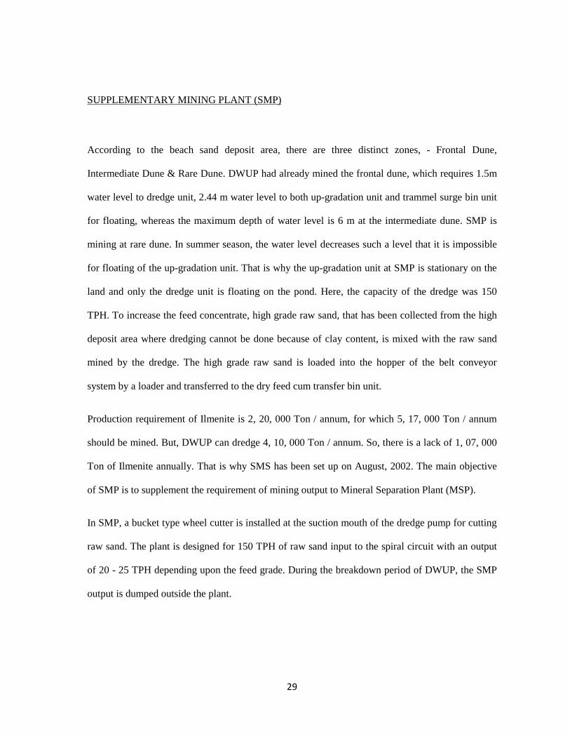
SUPPLEMENTARY MINING PLANT (SMP)
According to the beach sand deposit area, there are three distinct zones, - Frontal Dune,
Intermediate Dune & Rare Dune. DWUP had already mined the frontal dune, which requires 1.5m
water level to dredge unit, 2.44 m water level to both up-gradation unit and trammel surge bin unit
for floating, whereas the maximum depth of water level is 6 m at the intermediate dune. SMP is
mining at rare dune. In summer season, the water level decreases such a level that it is impossible
for floating of the up-gradation unit. That is why the up-gradation unit at SMP is stationary on the
land and only the dredge unit is floating on the pond. Here, the capacity of the dredge was 150
TPH. To increase the feed concentrate, high grade raw sand, that has been collected from the high
deposit area where dredging cannot be done because of clay content, is mixed with the raw sand
mined by the dredge. The high grade raw sand is loaded into the hopper of the belt conveyor
system by a loader and transferred to the dry feed cum transfer bin unit.
Production requirement of Ilmenite is 2, 20, 000 Ton / annum, for which 5, 17, 000 Ton / annum
should be mined. But, DWUP can dredge 4, 10, 000 Ton / annum. So, there is a lack of 1, 07, 000
Ton of Ilmenite annually. That is why SMS has been set up on August, 2002. The main objective
of SMP is to supplement the requirement of mining output to Mineral Separation Plant (MSP).
In SMP, a bucket type wheel cutter is installed at the suction mouth of the dredge pump for cutting
raw sand. The plant is designed for 150 TPH of raw sand input to the spiral circuit with an output
of 20 - 25 TPH depending upon the feed grade. During the breakdown period of DWUP, the SMP
output is dumped outside the plant.
30
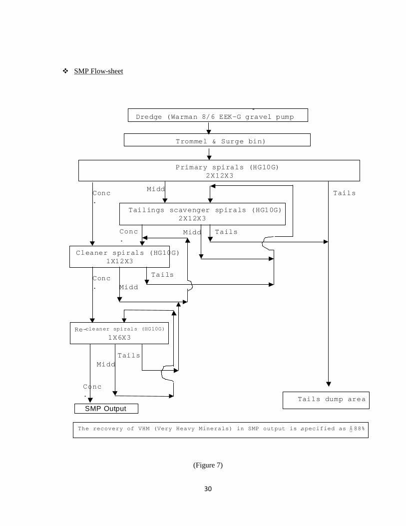
� SMP Flow-sheet
(Figure 7)
The grade of SMP Output shall be 80-90% HM provided that the feed grade does not fall below 14% HM
Primary spirals (HG10G) 2X12X3
Tailings scavenger spirals (HG10G) 2X12X3
Cleaner spirals (HG10G) 1X12X3
Re-cleaner spirals (HG10G) 1X6X3
Tails dump area
Tails Midd
Conc.
Conc.
Midd Tails
Tails
Midd Conc.
Conc.
Midd Tails
Dredge (Warman 8/6 EEK-G gravel pump
Trommel & Surge bin)
The recovery of VHM (Very Heavy Minerals) in SMP output is specified as 88% .
SMP Output
�
-
31
MINERAL SEPARATION PLANT (MSP)
In MSP, the heavy minerals like ilmenite, rutile, monazite, zircon and sillimanite are separated
from the upgraded feed minerals on the basis of their physical properties like electro-static,
magnetic property, specific gravity and surface characteristics.
The heavy minerals are received from the DWUP and SMP at the Re-pulping area of MSP. These
materials are pumped for up-gradation in Heavies Up-gradation Plant (HUP) at MSP. Whenever
HUP is not in operation, the material is stock-piled at RPA. These accumulated heavies are pushed
for pumping to HUP with the help of Earth Moving Equipments, whenever required by HUP.
In HUP, the feed is treated in gravity separation equipment like spirals using slurry pumps. The
lighter unwanted material is pumped to the reject dumping yard and the upgraded heavy mineral is
pumped to the dry feed yard through hydro-cyclones for natural de-watering and finally it is fed to
the main plant by EMEs for drying.
In the main plant, the feed material is dried by rotary dryer of 50 TPH capacity using furnace oil.
Then, the dried feed material is fed to High Tension Separators (HTS), where conducting minerals
like ilmenite and rutile are separated out from the non-conducting minerals like zircon, monazite,
sillimanite and garnet. Then, the conducting part is fed to Induced Roll Magnetic Separator (IRMS)
and the ilmenite, being magnetic, separated out from non-magnetic rutile and stored in the ilmenite
wire house. For further recovery of the products, the middling fraction of HTS and IRMS are
treated in shaft dryers followed by HTS, Electro-static Plate Separator (EPS), Rare Earth Drum
Separator (RED) and IRMS
32
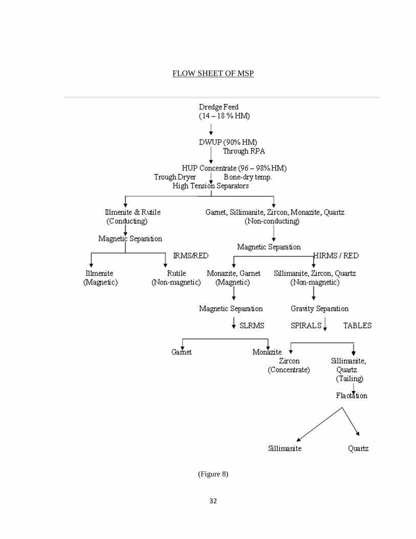
FLOW SHEET OF MSP
(Figure 8)
33
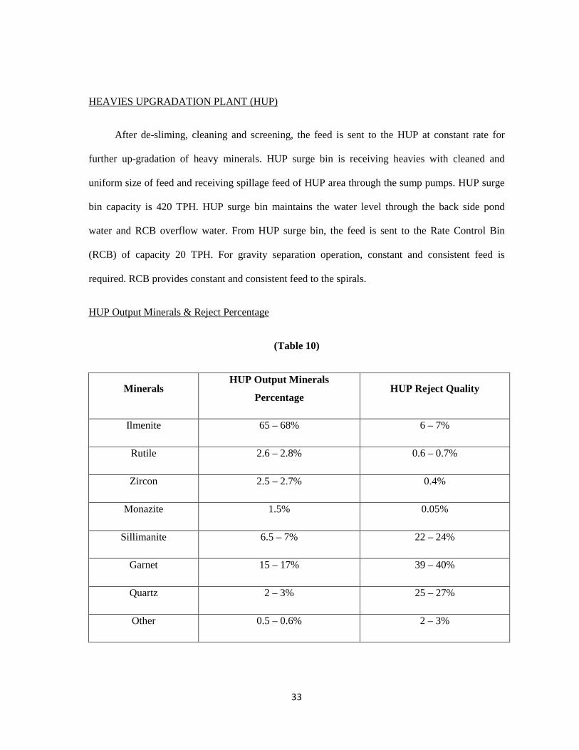
HEAVIES UPGRADATION PLANT (HUP)
After de-sliming, cleaning and screening, the feed is sent to the HUP at constant rate for
further up-gradation of heavy minerals. HUP surge bin is receiving heavies with cleaned and
uniform size of feed and receiving spillage feed of HUP area through the sump pumps. HUP surge
bin capacity is 420 TPH. HUP surge bin maintains the water level through the back side pond
water and RCB overflow water. From HUP surge bin, the feed is sent to the Rate Control Bin
(RCB) of capacity 20 TPH. For gravity separation operation, constant and consistent feed is
required. RCB provides constant and consistent feed to the spirals.
HUP Output Minerals & Reject Percentage
(Table 10)
Minerals HUP Output Minerals
Percentage HUP Reject Quality
Ilmenite 65 – 68% 6 – 7%
Rutile 2.6 – 2.8% 0.6 – 0.7%
Zircon 2.5 – 2.7% 0.4%
Monazite 1.5% 0.05%
Sillimanite 6.5 – 7% 22 – 24%
Garnet 15 – 17% 39 – 40%
Quartz 2 – 3% 25 – 27%
Other 0.5 – 0.6% 2 – 3%
34
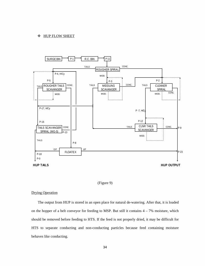
� HUP FLOW SHEET
(Figure 9)
Drying Operation
The output from HUP is stored in an open place for natural de-watering. After that, it is loaded
on the hopper of a belt conveyor for feeding to MSP. But still it contains 4 – 7% moisture, which
should be removed before feeding to HTS. If the feed is not properly dried, it may be difficult for
HTS to separate conducting and non-conducting particles because feed containing moisture
behaves like conducting.
ROUGHER SPIRAL
SURGE BIN R.C. BIN P-11P-1
ROUGHER TAILS SCAVANGER
CLEANER SPIRAL
CLNR TAILSSCAVANGER
MIDDLING SCAVANGER
FLOATEX
TAILS SCAVANGERSPIRAL (MG-5)
P-2
P-4, H/Cy
P-5 P-3
P-9
P-23
HUP TAILS
P-18
P-0
HUP OUTPUT
P-13
P-16
P-17, H/Cy
P-8
P -7, H/Cy
P-12
O/F
CONC.
CONC.
CONC.
CONC.CONC.
CONC.
MIDD.
MIDD. MIDD.MIDD.
TAILSTAILSTAILS
TAILS
MIDD.
TAILS
U/F
TAILS
35
EQUIPMENTS
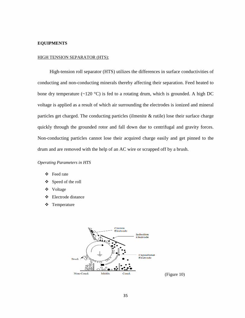
HIGH TENSION SEPARATOR (HTS):
High-tension roll separator (HTS) utilizes the differences in surface conductivities of
conducting and non-conducting minerals thereby affecting their separation. Feed heated to
bone dry temperature (~120 °C) is fed to a rotating drum, which is grounded. A high DC
voltage is applied as a result of which air surrounding the electrodes is ionized and mineral
particles get charged. The conducting particles (ilmenite & rutile) lose their surface charge
quickly through the grounded rotor and fall down due to centrifugal and gravity forces.
Non-conducting particles cannot lose their acquired charge easily and get pinned to the
drum and are removed with the help of an AC wire or scrapped off by a brush.
Operating Parameters in HTS
� Feed rate
� Speed of the roll
� Voltage
� Electrode distance
� Temperature
(Figure 10)
36
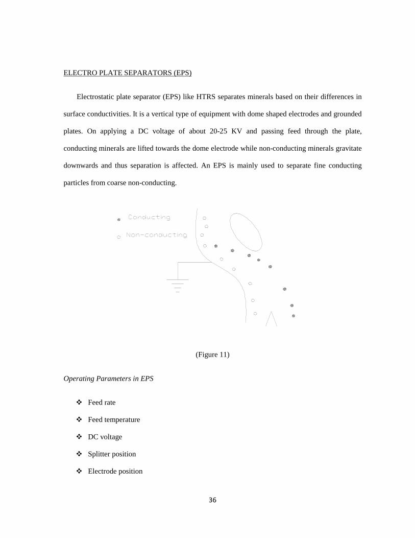
ELECTRO PLATE SEPARATORS (EPS)
Electrostatic plate separator (EPS) like HTRS separates minerals based on their differences in
surface conductivities. It is a vertical type of equipment with dome shaped electrodes and grounded
plates. On applying a DC voltage of about 20-25 KV and passing feed through the plate,
conducting minerals are lifted towards the dome electrode while non-conducting minerals gravitate
downwards and thus separation is affected. An EPS is mainly used to separate fine conducting
particles from coarse non-conducting.
(Figure 11)
Operating Parameters in EPS
� Feed rate
� Feed temperature
� DC voltage
� Splitter position
� Electrode position
37
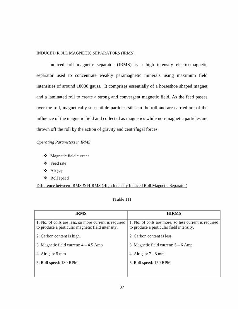
INDUCED ROLL MAGNETIC SEPARATORS (IRMS)
Induced roll magnetic separator (IRMS) is a high intensity electro-magnetic
separator used to concentrate weakly paramagnetic minerals using maximum field
intensities of around 18000 gauss. It comprises essentially of a horseshoe shaped magnet
and a laminated roll to create a strong and convergent magnetic field. As the feed passes
over the roll, magnetically susceptible particles stick to the roll and are carried out of the
influence of the magnetic field and collected as magnetics while non-magnetic particles are
thrown off the roll by the action of gravity and centrifugal forces.
Operating Parameters in IRMS
� Magnetic field current
� Feed rate
� Air gap
� Roll speed
Difference between IRMS & HIRMS (High Intensity Induced Roll Magnetic Separator)
(Table 11)
IRMS HIRMS
1. No. of coils are less, so more current is required to produce a particular magnetic field intensity.
2. Carbon content is high.
3. Magnetic field current: 4 – 4.5 Amp
4. Air gap: 5 mm
5. Roll speed: 180 RPM
1. No. of coils are more, so less current is required to produce a particular field intensity.
2. Carbon content is less.
3. Magnetic field current: 5 – 6 Amp
4. Air gap: 7 - 8 mm
5. Roll speed: 150 RPM
38
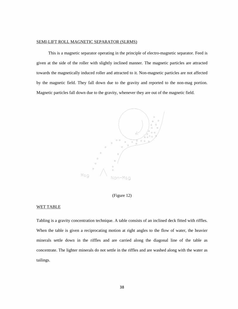
SEMI-LIFT ROLL MAGNETIC SEPARATOR (SLRMS)
This is a magnetic separator operating in the principle of electro-magnetic separator. Feed is
given at the side of the roller with slightly inclined manner. The magnetic particles are attracted
towards the magnetically induced roller and attracted to it. Non-magnetic particles are not affected
by the magnetic field. They fall down due to the gravity and reported to the non-mag portion.
Magnetic particles fall down due to the gravity, whenever they are out of the magnetic field.
(Figure 12)
WET TABLE
Tabling is a gravity concentration technique. A table consists of an inclined deck fitted with riffles.
When the table is given a reciprocating motion at right angles to the flow of water, the heavier
minerals settle down in the riffles and are carried along the diagonal line of the table as
concentrate. The lighter minerals do not settle in the riffles and are washed along with the water as
tailings.
39
The table decks are usually constructed of wood, lined with materials having high co-efficient of
friction, such as rubber. Decks made of fiberglass are highly wear resistant, but more expensive.
The table is reciprocated by toggle mechanism due to which forward motion is slow and
return stroke is rapid. An unbalanced mass is placed on a shaft eccentrically and the shaft
is connected to the motor. As the motor rotates, the toggle, which is connected to the shaft,
moves up and down. The toggle is connected to the yaw that imparts to and fro motion to
the wet table. At the opposite corner, there is compression spring. During the forward
movement of the table, the spring is compressed. When it returns to its original position,
the table is pulled at the same time. Both the movements are in same direction and so the
backward motion is rapid.
The operating parameters in wet table are, -
� Quantity of wash water
� Deck inclination
� Feed rate
� Stroke length
AIR TABLES
Air tables are gravity separators, which use air as a medium of separation. Low-
pressure air is admitted below the vibrating table whose surface is fitted with a perforated
cloth. The feed is introduced near the top of the inclined table. Lighter minerals are lifted
by the air and flow downward as tails. The oscillating motion of the table causes the heavy
minerals in contact with the table surface to move upward and is collected as concentrate.
40
The operating parameters in wet table are, -
� Quantity of air
� Deck inclination
� Feed rate
� Splitter opening
FROTH FLOATATION TECHNIQUE
Froth floatation utilizes the difference in physicochemical surface properties of particles of
minerals. After treatment with reagents, such differences in surface properties between the minerals
within the floatation pulp become apparent and, for floatation to take place, an air-bubble must be
able to attach itself to a particle, and lift it to the water surface. The air bubble can only stick to the
mineral particles if they can displace water from mineral surface, which can only happen if the
mineral is to some extent water repellant or hydrophobic. To achieve this condition it is necessary
to use the numerous selective chemical reagents known as floatation reagents or surfactants.
The floatability of mineral increases with the contact angle; minerals having high contact
angle are said to be having a higher affinity for air than for water. Most minerals are not water
repellent in their natural state & floatation reagents are to be added to the pulp. The most important
reagents are the collectors, which absorb on mineral surfaces, rendering them hydrophobic and
facilitating bubble attachment. They help maintain a reasonably stable froth.
41
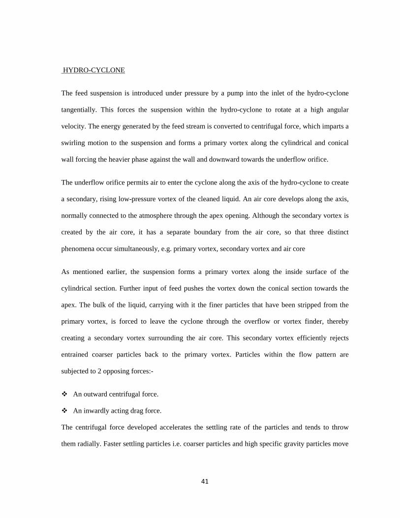
HYDRO-CYCLONE
The feed suspension is introduced under pressure by a pump into the inlet of the hydro-cyclone
tangentially. This forces the suspension within the hydro-cyclone to rotate at a high angular
velocity. The energy generated by the feed stream is converted to centrifugal force, which imparts a
swirling motion to the suspension and forms a primary vortex along the cylindrical and conical
wall forcing the heavier phase against the wall and downward towards the underflow orifice.
The underflow orifice permits air to enter the cyclone along the axis of the hydro-cyclone to create
a secondary, rising low-pressure vortex of the cleaned liquid. An air core develops along the axis,
normally connected to the atmosphere through the apex opening. Although the secondary vortex is
created by the air core, it has a separate boundary from the air core, so that three distinct
phenomena occur simultaneously, e.g. primary vortex, secondary vortex and air core
As mentioned earlier, the suspension forms a primary vortex along the inside surface of the
cylindrical section. Further input of feed pushes the vortex down the conical section towards the
apex. The bulk of the liquid, carrying with it the finer particles that have been stripped from the
primary vortex, is forced to leave the cyclone through the overflow or vortex finder, thereby
creating a secondary vortex surrounding the air core. This secondary vortex efficiently rejects
entrained coarser particles back to the primary vortex. Particles within the flow pattern are
subjected to 2 opposing forces:-
� An outward centrifugal force.
� An inwardly acting drag force.
The centrifugal force developed accelerates the settling rate of the particles and tends to throw
them radially. Faster settling particles i.e. coarser particles and high specific gravity particles move
42
to the wall of the hydro-cyclone and descend in a spiral flow pattern to the underflow orifice also
known as apex or spigot.
Due to the action of the drag force, the slower-settling particles, i.e. water and the particles in the
feed stream which are lower in specific gravity, follow the major portions of the flow to the centre
of the core where they are caught in the high velocity upward central current in the zone of low
pressure along the axis and are carried out through the vortex finder to the overflow.
(Figure 13)
43
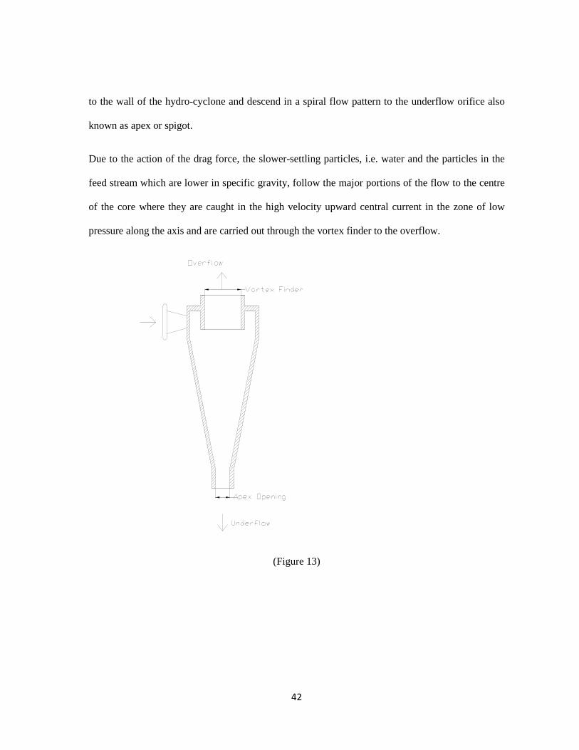
FLOATEX
(Figure 14)
Floatex or Hydro-seizer is a gravity separator used for separating heavier particles from
lighter particles in the principle of hindered settling. After entering the floatex, water
moves in upward direction and thus restricting the settling of the particles. At any position,
the particle will experience gravity force in downward and buoyancy force in upward
direction. At a certain position, the particles will be in equilibrium condition under the
above forces. So, the particles become stagnant at that position. After some times, more
particles are in such condition and thus a fluidized bed has been formed. The particles
having higher specific gravity settle down and are collected as underflow. The particle of
lower specific gravity are carried away by the upward flowing water and removed from the
floatex chamber as overflow
44
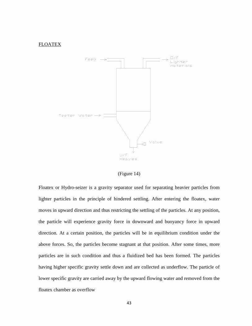
QUALITY CONTROL
� Independent collection, analysis and reporting of final MSP product samples.
� Analysis and reporting of final Thorium plant product samples for quality
control.
� Analysis for quality control of chemicals received at Central stores as per
order.
Regarding quality control aspect, Technical Service is continuously checking the
following specification and impurities content of the minerals before giving them
confirmation for marketing.
(Table 12)
Minerals Ilmenite Rutile Zircon Garnet Sillimanite
Product Specification (%)
98.5 97.5 97.5 94 92.5
Impurities in product (max %)
Gar-1 Mon-0.1
Zir-1.5 Mon-0.3
Sill-2, Rut-0.5 Mon-0.3
Ilm-4.0 Qtz-4 Mon-0.3
Guaranteed (minimum) for
marketing
50.25% TiO2 94.25% TiO2 64.25 % (ZrO2 + HfO2)
94 % (Garnet)
56.5 % (Al 2O3)
Packaging and Pricing (Table 13)
Products Price (Rs. / MT) Packing
Rutile 41,000.00 50 Kg. bag
Zircon 40,000.00 50 Kg. bag
Ilmenite 5000.00 Loose
Sillimanite 12,000.00 Loose
Garnet 4000.00 Loose
Thorium Nitrate 4,30,000.00 50 Kg. Drum
45
Chapter 5
IMPEDIMENTS & ADVANTAGES
46
IMPEDIMENTS TO PLACER MINING
Land Acquisition is an issue. The area under lease has decreased owing to various social,
cultural & environmental issues.
These minerals are a strategic asset. Secrecy is maintained with regards to shipment and
production data. The lease area is cordoned off to safeguard the precious deposits.
The CRZ notification has further deprived IREL of dredging activities within 100 metres
of the High Tide Line.
Availability of fresh water for the artificial pond is an issue.
Dredging can create disturbances to aquatic ecosystems, often with adverse impacts. In addition,
dredge spoils may contain toxic chemicals that may have an adverse impact on the disposal area;
furthermore, the process of dredging often dislodges chemicals residing in benthic substrates and
injects them into the water column. The activity of dredging can create the following impacts to the
environment:
Release of toxic chemicals (including heavy metals and PCB) and bottom sediments into
the water column.
Short term increase in turbidity, which can affect aquatic species metabolism and interfere
with metabolism and interfere with spawning.
Secondary effects from water column contamination of uptake of heavy metals, DDT and
other persistent organic toxins, via food chain uptake and subsequent concentrations of
these toxins in higher organisms including humans.
Secondary impacts to marsh productivity from sedimentation
Tertiary impacts to avifauna which may prey upon contaminated aquatic organisms
Secondary impacts to aquatic and benthic organisms' metabolism and mortality.
47
ADVANTAGES IN PLACER MINING
As it is already loose material hence cost up to 40-50% is reduced.
Precautions are always desired but safety issues are not a conundrum as compared to
underground mining.
The deposits in Orissa were formed long ago and are no longer in formation stage,
however in Kerala and Kanyakumari the deposits are being readily formed and they are
extracted by beach washing. The MoEF may in certain cases allow beach washing of
deposits lying within CRZ.

48
Chapter 6
CONCLUSION
49
Indian Rare Earths Ltd. is one among well performing companies in the public sector, engaged in
the processing of beach sand minerals available along the coastal belt. The organization study in
this unit is an unforgettable experience. The work culture, the concern for safety and environment
issues and social responsibility prevailed in this organization is worth studying. This study helped
in having a practical exposure to mining as well as mineral processing activities of the
organization.
With the advent of technology and increasing metal prices across the world it is expected that
placer and seabed mining would be the need of the future. These are the resources that have largely
remained untapped. It is desirable that the government take adequate steps for proper exploitation
of these resources.
With the amount of talent pool available in India, and new advances being made in the mining as
well as processing technology it is imperative that the costs would come down.
50
Chapter 7
REFERENCES
51
� T. K. Mukherjee , CMD & A.K.Das, GM (S&E), “FALL OUT OF NEW BEACH
SAND MINERAL POLICY”, Indian Rare Earths Ltd.
� Rajamanickam G. Victor, Varma O.P., and Gujar A.R., “ Ilmenite placer
deposits in the bays of Jaigad, Ambwah, and Varvada, Maharashtra, India”;
Geological Survey of India.
� Sharma Rahul, “Environmental studies for Deep Seabed Mining,” National
Institute of Oceanography, Goa.
� Training Brochure at IREL , Chatrapur, Ganjam, Orissa.
� Markussen J.M., “Deep Seabed Mining and the Environment: Consequences,
Perceptions and Regulations”.


![Significant Metalliferous Lode Deposits and Placer ...Placer deposits-Alaska. 2. Ore deposits-Alaska. I. Nokleberg, Warren J. II. Series. QE75.B9 No. 1786 557.3 s 87-600165 [TN24.A4]](https://img.pdfslide.us/doc/110x75/60f8d1a3a30d24483962b191/significant-metalliferous-lode-deposits-and-placer-placer-deposits-alaska-2.jpg)