Embed Size (px)
Citation preview
Computers and Chemical Engineering 24 (2000) 2093–2113
A review of recent design procedures for water networks inrefineries and process plants�
Miguel Bagajewicz *School of Chemical Engineering and Materials Science, Uni6ersity of Oklahoma, 100 E. Boyd St, T-335, Norman, OK 73019, USA
Abstract
This paper presents a review of the procedures to design and retrofit water networks. Although the emphasis is in showingresults for refineries, the methods are valid for any process plants. It is first shown that the problem has been decomposed intothe design of two interacting subsystems. One problem is the freshwater and wastewater reuse allocation and the other is thewastewater treatment problem. It is also shown how the wastewater treatment problem was modeled as a distributed anddecentralized treatment. The roadmap towards zero liquid discharge and energy integrated solutions is then discussed. Severalsolution approaches are briefly outlined emphasizing the main trend leaning towards the use of mathematical programming. Themajor claim made is that mathematical programming can produce globally optimal solutions and practically importantsub-optimal solutions when conceptual insights are employed to build the models. Although the paper intends to be comprehen-sive, it emphasizes the author’s recent work. Finally, a few of the existing challenges of the area are outlined. © 2000 ElsevierScience Ltd. All rights reserved.
Keywords: Water systems; Wastewater minimization; Wastewater reuse; Wastewater recycle; Wastewater regeneration; Wastewater treatment
www.elsevier.com/locate/compchemeng
1. Introduction
Water is a key element for the normal functioning ofthe chemical and petrochemical industry. Steam strip-ping, liquid–liquid extraction and washing operationsare among the many processes present in refineries andchemical plants where water is intensively utilized.
In refineries, steam is used in atmospheric and vac-uum crude fractionation, as well as in coking, hydroc-racking, FCC, visbreaking, sweetening, hydrotreating,alkylation, ether synthesis, etc. In addition, water isused in desalters to remove primarily the salted waterdroplets that the crude contains. However, several othercontaminants are also removed (H2S, suspended solids,ammonia, etc). In caustic treating water is used and theprincipal contaminants are H2S, ammonia, phenol,mercaptans, etc. Water is also intensively used in hy-drometallurgy where many suspended solids as well asa large variety of ionic metals can be found. In addi-
tion, since liquid–liquid extraction is often used, or-ganic solids are also present. In the iron and steelindustry vast amounts of water are used in cooling ofblast furnaces and casting machinery, quenching ofslag, scrubbing of gases with waste waters containingsulfides, cyanides, sulfur dioxide, calcium oxide andchromates. The food and agricultural industries (sugarfactories, dairy industries, breweries) make use of waterfor a variety of washing operations and steam in evapo-rators. Other industries with intense use of water arethe textile industry, the pharmaceutical and electroniccomponent industry.
Several measures exist to assess the quality of waterfor discharge. For example, the total organic carbon(TOC), the biochemical oxygen demand (BOD) and thechemical oxygen demands (COD) indicate the organicmatter content. Oil and grease (O&G) and totalpetroleum hydrocarbons (TPH) give a measure of thepresence of oil, grease and other hydrocarbons. Thephysical characteristics of the wastewater are also ad-justed before disposal. These characteristics include thetotal suspended solids (TSS), pH, temperature, colorand odor. In compliance with the United States EPAClean Water Act of 1977, wastewater must be treated
� II Pan American Workshop in Catalysis and Process SystemsEngineering, September 2–3, 1999, Santa Fe, Argentina
* Tel.: +1-405-3255811; fax: +1-405-3255813.E-mail address: [email protected] (M. Baga-
jewicz).
0098-1354/00/$ - see front matter © 2000 Elsevier Science Ltd. All rights reserved.PII: S0098-1354(00)00579-2

M. Bagajewicz / Computers and Chemical Engineering 24 (2000) 2093–21132094
before discharge (that is, end of pipe treatment). Sev-eral treatment options are taken into account depend-ing on the sludge characterization. In other words:wastewater treatment procedures are based on the typeand concentration of its contaminants.
In refineries, treatment is divided in four levels: pri-mary treatment involves physical treatment processes,secondary treatment comprises operations where solu-ble matter is removed, and tertiary and quaternarytreatments ‘polish’ the effluent to the final dischargestandards. In other industries, this classification issometimes also found. Regardless of the treatmentlevel, the unit operations for wastewater treatment areclassified as physical (air flotation, oil coalescing, evap-oration, filtration, etc.), chemical (precipitation, coagu-lation, ion exchange, etc.), thermal, and biological.
Several procedures have been proposed to designeconomical wastewater treatment. With a few excep-tions, these procedures rely on the application of cer-tain rules of thumb. The current installations usuallymerge several waste streams and use appropriate tech-nologies in series to clean this stream before disposal.These are therefore, end-of-pipe non-distributedwastewater cleanup solutions. Several papers discussthese options. Belhateche (1995) offers a complete dis-cussion of these technologies.
Starting in the eighties and increasingly in the nine-ties, water re-use started to become popular as a meansof reducing the total amount of water intake. This, inturn, not only saves upstream treatment of raw waterbut also reduces wastewater treatment costs. In addi-tion, the concept of distributing the treatment amongthe various polluted streams and even decentralizing itis gaining acceptance. Industry and the EPA in the USare also seriously considering and discussing the advan-tages and disadvantages of zero liquid discharge solu-tions as the ultimate goal of green water utilization inprocess plants.
In this paper, the state of the art in water allocationand water treatment process solutions is reviewed. Spe-cial emphasis is put to discuss those methods based onmathematical programming, as they are becoming thefocus approach that almost all researchers are using tosolve these problems. The central claim made in thisreview is that mathematical programming can effi-ciently produce globally optimal and sub-optimal solu-tions if conceptual insights are made to properly buildthe models.
2. Roadmap for improved process solutions
Until a few years ago, the problem of water treat-ment was considered as a set of sequential treatmentoperations of a single wastewater stream consisting ofthe wastewater from all unit operations (desalters, strip-pers, etc). At the same time, without the concept ofwastewater reuse, these processes are fed by freshwateronly. Such a system is depicted for three water userprocesses (Pi) and three treatment units (Ti) in Fig.1(a). One way of obtaining improved designs is thereuse of wastewater from one process to feed anotherwithout sending it to treatment first. This reduces thecost because the overall water intake is smaller (Fig.1(b)). The next step is to introduce series/parallel de-signs of the wastewater treatment unit without mergingall the wastewater streams (Fig. 1(c)). Finally, treat-ment can be decentralized in such a way that somepollutants are removed from wastewater of selectedprocesses allowing the reuse of these waters (Fig. 1(d)).
The concept of zero discharge applies alternatively tothe total elimination of the disposal of environmentallyhazardous substances or to the concept of a closedcircuit of water, such that water disposal is eliminatedaltogether, that is zero ‘liquid’ discharge. Closed cir-cuits are appealing because end-of-pipe regeneration
Fig. 1. Water utilization systems in process plants.
M. Bagajewicz / Computers and Chemical Engineering 24 (2000) 2093–2113 2095
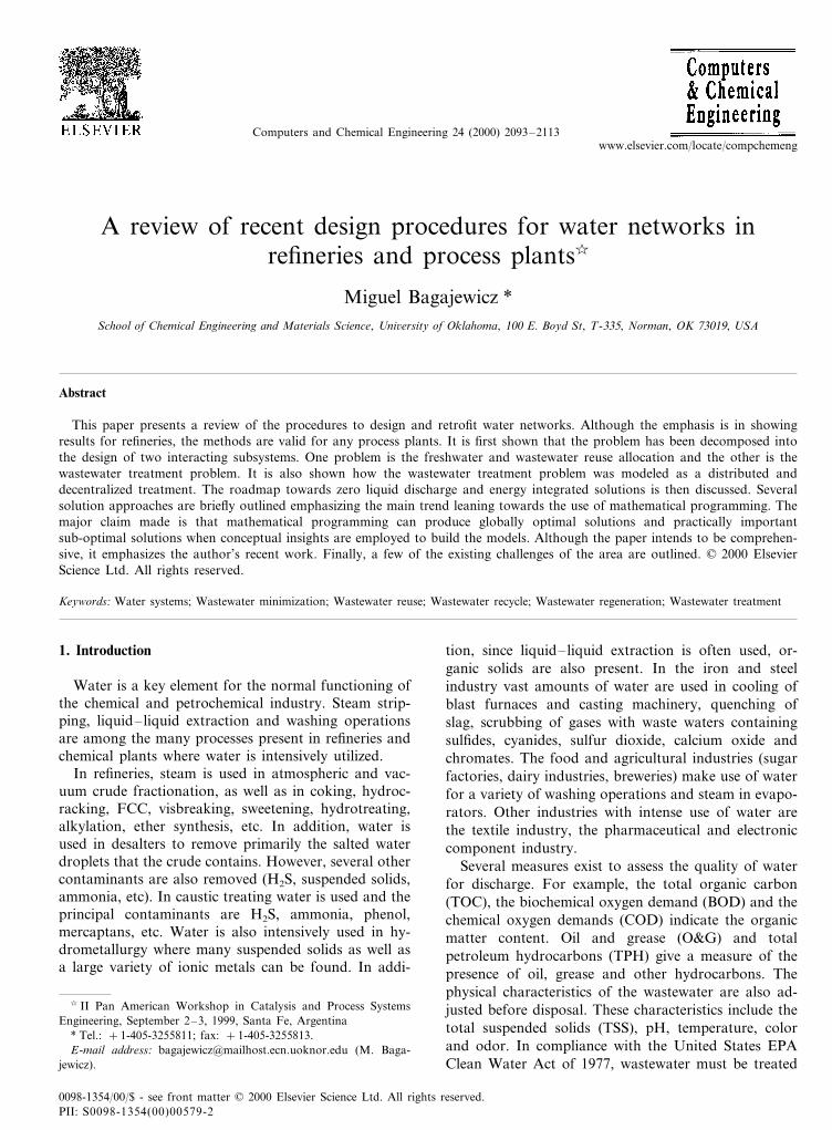
Fig. 2. A zero liquid discharge scheme.
There have been traditionally two approaches used toobtain good designs of these systems:� conceptual approach;� mathematical programming.
It is interesting to note that the seminal paper of thisarea (Takama, Kuriyama, Shiroko & Umeda, 1980)proposed a mathematical programming approach todesign a structure similar to the one in Fig. 1(d).However, in view of all the implementation limitationsand difficulties that the approach used by Takama et al.(1980) presented, the conceptual approach that domi-nated the field using structures like the one in Fig. 1(a)or (b). However, in the last few years, the conceptualdesign paradigm is showing limitations to address thecomplexity of the problem. Despite these limitations,the conceptual approach has provided a simplified de-scription of the problem that has been of great value tobuild effective mathematical programming models. Re-cent work is proving that a synergistic combination ofboth approaches, that is, the use of conceptual insightsto help formulating better models for mathematicalprogramming (good initial points, heuristics to help inbranch an bound procedures, use of necessary condi-tions of optimality, etc) is at this point in time showingto be the most effective alternative.
Graphical insights are of importance in practice be-cause they allow the engineer to incorporate manyfactors that mathematical programming does not con-sider. Thus, the field has evolved from a paradigmwhere a graphical insight was used to obtain a design toanother where a mathematical is used, from which agraphical representation is obtained.
As it was outlined above, the research communityhas not addressed the problem of optimizing the struc-ture of Fig. 2 directly. It has instead focused in thesolution of either the minimization of freshwater usagethrough re-use and proper allocation of wastewater, orthe series/parallel clean-up structure. That is, it haspartitioned the problem of Fig. 1(c) into two sub-prob-lems. We now review the work performed in each ofthese sub-problems separately.
3. Optimal water/wastewater allocation
The search for optimal wastewater reuse solutionswas addressed by industry itself more than 20 years ago(Carnes, Ford & Brady, 1973; Skylov & Stenzel, 1974;Hospondarec & Thompson, 1974; Mishra, Fan & Er-ickson, 1975; Anderson, 1977; Sane & Atkins, 1977).Takama et al. (1980) used mathematical programmingto solve a refinery example. A superstructure of allwater-using operations and cleanup processes was setup and an optimization was then carried out to reducethe system structure by removing irrelevant and uneco-nomical connections. The authors made an important
does not have to be conducted to the full extent re-quired for disposal as water can be reused with higherlevel of contaminants (Fig. (2)). Additionally, the ab-sence of a discharge eliminates internal administrativecosts associated with the enforcement of environmentalprotection agencies and local limits as well as theinterface with other government agencies.
These zero discharge process solutions have neverbeen attempted, neither in academic case studies, andapparently nor in practice. They constitute the burningchallenge for both academia and industry. There arehowever, a few issues than can readily be pointed out.First, many units require steam, that is, pure freshwater of boiler quality. Thus, in order for these zerodischarge cycles to exist, wastewater cleanup should bethorough, something that could be too expensive to berealistic. Second, unless an expensive total evaporationstep is included, some water make-up and disposalshould take place to avoid the accumulation of certainspecies not being removed.
The analysis made in this section suggests that inreality the problem one wishes to solve is the onedepicted in Fig. 2, which has all the previous alterna-tives embedded. Diepolder (1992) and Goldblatt, Ebleand Feathers (1993) discussed how realistic is this con-cept from the practical point of view, addressing issuessuch as the disposal of solids, the possible sizablerevenues obtained for the selling of low grade salts andavoiding their disposal (close to a million dollars peryear for a typical refinery), or the costs of disposal ofgroundwater solids, etc.
To attack the problem at its roots, i.e. the generationof pollutants, process simulation was proposed as atool to perform pollution balances on processes andcalculates pollution indices (Sowa, 1994; Hilaly & Sik-dar, 1996). One of the main results of this line of workis the WAR algorithm developed by the US EPA RiskReduction Engineering Laboratory. However, for manyprocesses the reduction of the generation of pollutantsis not possible. The petroleum processing industry issuch an example. The major pollutants in refinerywastewater are part of the crude and are not generatedin the plant. Many other pollutants are by-productsthat are difficult to reduce.

M. Bagajewicz / Computers and Chemical Engineering 24 (2000) 2093–21132096
Fig. 3. Targeting procedure for single component systems.
contribution by addressing the problem of water man-agement as a combination of water/wastewater alloca-tion among processes and wastewater distribution tocleanup units. This can be considered as the seminalpaper in this area.
Although multiple pollutants are almost alwayspresent, sometimes for the purpose of analyzing thereuse of wastewater, pollutants can be lumped in asingle pseudo-pollutant or ignored if their concentra-tion is too low. This has prompted a classification onsingle pollutants and multiple pollutants problems, forwhich a variety of methods have been developed. It wasnot until very recently when the issue of energy efficientutilization was researched.
The problem has received a lot of attention form theacademic community and from practitioners. At leastone book is devoted entirely to the problem (Mann &Liu, 1999) and another discusses it in detail (Rossiter,1995). In addition, there are a few commercial softwarecompanies offering products related to water manage-ment. Even though it seems like a separate area ofresearch, the problem is a mass exchange problem.Indeed, contrary to recent claims (Alva-Argaez, Val-lianatos & Kokossis, 1999), although some processesare not countercurrent mass exchangers, it can be mod-eled as a one lean stream (water) and many rich streams(processes) system.
3.1. Conceptual design procedures
The hierarchical design approach (Douglas, 1988),proposes to start with some critical equipment of theflowsheet (usually the reactor) and continue buildingthe flowsheet from the inside out going through theseparation system and later through the heat recoverysystem. As applied to water/wastewater reuse systemsthe conceptual design approach was initiated by RobinSmith from UMIST, who proposed a targeting proce-dure that allows the calculation of the minimum freshwater usage without the need of constructing a net-work. As it was pointed out above, the problem for onepollutant, can be entirely solved using mass exchange
network technology, as it was developed by the groupled by Professor Manousiouthakis from UCLA.
3.2. Targeting for fresh water usage
The targeting graphical method exploits the idea ofplotting the cumulative exchanged mass versus compo-sition for a set of rich and lean streams, a concept firstpresented by El-Halwagi and Manousiouthakis (1989)for synthesizing mass exchanger networks. Wang andSmith (1994a) proposed a methodology that can effec-tively pick optimal reuse solutions. Dhole, Ramchan-dani, Tainsh and Wasilewski (1996) popularized thismethodology calling it the ‘water pinch’. The method isbased on assuming:� Constant pollutant load picked up in each process.
This is a fair simplifying assumption.� Maximum inlet and outlet concentrations in each
process. These are dictated by solubility, flow ratelimitations, fouling.By combining all these streams in one unique profile,
a water limiting profile can be obtained, as it is shownin Fig. 3 for four processes. The fresh water linetouches the composite curve at the pinch point anddetermines the overall water consumption. Once thetarget flow rate is obtained, a preliminary network isdeveloped using a matching procedure, which is brieflyillustrated next. Consider the data given in Table 1.
Wang and Smith (1994a) proposed two techniques:‘maximum driving forces’ and ‘minimum number ofwater sources’. The first one showed some limitationsand will not be discussed further. The first step of the
Table 1Example from Wang and Smith (1994a)
Coutmax (ppm)Process number C in
max (ppm)Contaminantload (kg h−1)
0 1002.011002 505.0
30.0 50 80038004 4.0 400
M. Bagajewicz / Computers and Chemical Engineering 24 (2000) 2093–2113 2097
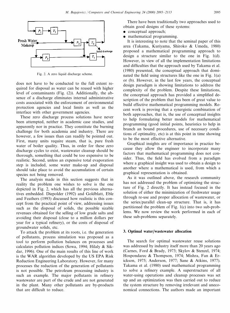
Fig. 4. Single contaminant design grid procedure (following Wang & Smith, 1994a).
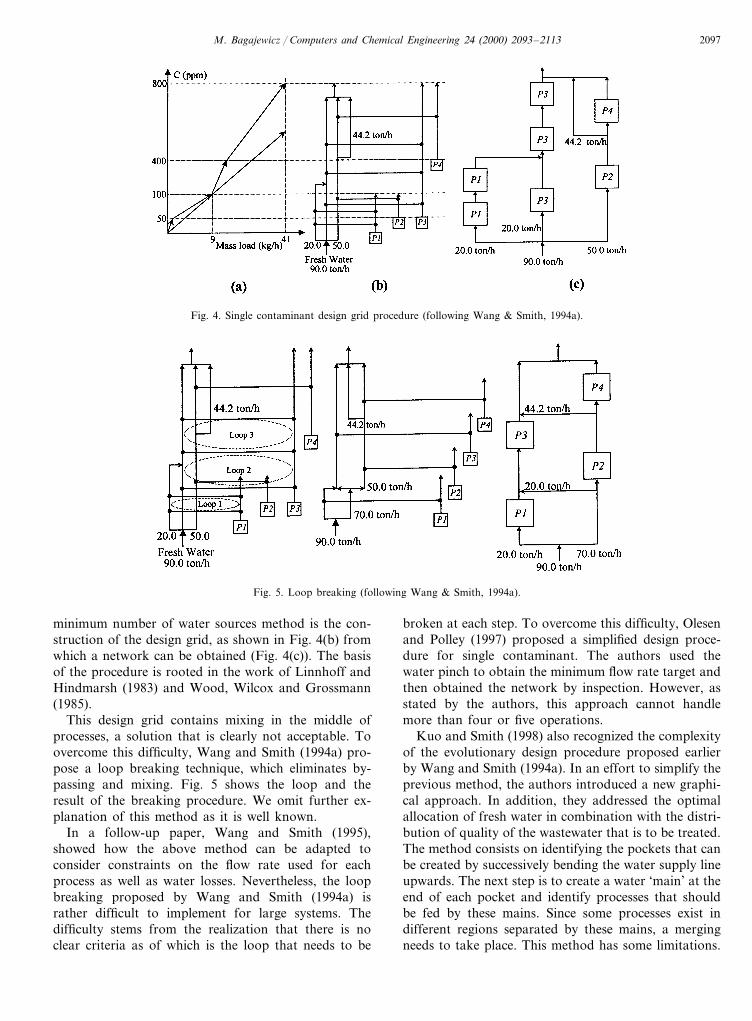
Fig. 5. Loop breaking (following Wang & Smith, 1994a).
minimum number of water sources method is the con-struction of the design grid, as shown in Fig. 4(b) fromwhich a network can be obtained (Fig. 4(c)). The basisof the procedure is rooted in the work of Linnhoff andHindmarsh (1983) and Wood, Wilcox and Grossmann(1985).
This design grid contains mixing in the middle ofprocesses, a solution that is clearly not acceptable. Toovercome this difficulty, Wang and Smith (1994a) pro-pose a loop breaking technique, which eliminates by-passing and mixing. Fig. 5 shows the loop and theresult of the breaking procedure. We omit further ex-planation of this method as it is well known.
In a follow-up paper, Wang and Smith (1995),showed how the above method can be adapted toconsider constraints on the flow rate used for eachprocess as well as water losses. Nevertheless, the loopbreaking proposed by Wang and Smith (1994a) israther difficult to implement for large systems. Thedifficulty stems from the realization that there is noclear criteria as of which is the loop that needs to be
broken at each step. To overcome this difficulty, Olesenand Polley (1997) proposed a simplified design proce-dure for single contaminant. The authors used thewater pinch to obtain the minimum flow rate target andthen obtained the network by inspection. However, asstated by the authors, this approach cannot handlemore than four or five operations.
Kuo and Smith (1998) also recognized the complexityof the evolutionary design procedure proposed earlierby Wang and Smith (1994a). In an effort to simplify theprevious method, the authors introduced a new graphi-cal approach. In addition, they addressed the optimalallocation of fresh water in combination with the distri-bution of quality of the wastewater that is to be treated.The method consists on identifying the pockets that canbe created by successively bending the water supply lineupwards. The next step is to create a water ‘main’ at theend of each pocket and identify processes that shouldbe fed by these mains. Since some processes exist indifferent regions separated by these mains, a mergingneeds to take place. This method has some limitations.
M. Bagajewicz / Computers and Chemical Engineering 24 (2000) 2093–21132098
For example, when several processes below the pinchhave maximum inlet concentration larger than zero, itis not quite simple to identify which process needs to befed using fresh water first and to what process eachwastewater has to be sent. This was clarified later bySavelski and Bagajewicz (1999a,b, 2000a) by introduc-ing the concept of monotonicity in the process-to-pro-cess connections. In addition, Gomez, Savelski &Bagajewicz (2000) provided an algorithmic procedureto address this matter.
3.3. Multicomponent systems
Wang and Smith (1994a) also attempted to address atargeting and network design procedure for the case ofmulticomponent systems. Targeting proved to be verycumbersome, as it required elaborate special shifting ofstreams in the concentration–load diagram. Themethod proved to have limitations as it fails to identifyoptimal solutions. Liu (1999) presented a few interest-ing heuristic rules. Although some of them are incor-rect, the solution procedure has remarkable simplicityand provides good sub-optimal (and sometimes opti-mal) solutions.
3.4. Data gathering
While all the above methods and the mathematicalprogramming approaches have various degrees of suc-cess in solving the problem, data gathering and estab-lishing proper constraints (maximum inlet and outletconcentrations) is a practical problem that has not yetbeen addressed fully. The designer starts with uncertaindata, that is, not knowing well what are the acceptablewater specifications for each process. Some of thesespecifications, nevertheless are fairly straightforward.For example, maximum outlet concentrations are re-lated to solubility and some maximum inlet specifica-tions are process restrictions. In addition, oncemaximum outlet concentrations are established, inletmaximums can be obtained from the information onthe load and the minimum flow rate the equipment canhandle. Knowledge of the load is also an issue and inpractice cannot be inferred directly. The issue of uncer-tainty is further discussed later.
3.5. Mathematical programming procedures
After the pioneering work of Takama et al. (1980) nojournal publication addressed a mathematical program-ming formulation of the problem for several years.However, Doyle and Smith (1997) and more recentlyAlva-Argaez, Kokossis and Smith (1998a,b) and Alva-Argaez et al. (1999) as well as Huang, Chang, Ling andChang (1999) presented MINLP or NLP models. Work
performed related to single contaminant systems isreviewed first.
Savelski and Bagajewicz (2000a) showed that themodel for single component can be linearized. Indeed,assume that each water-using unit is characterized by acontaminant load that needs to be entirely removed andby inlet and outlet maximum concentration constraints.Then, the following NLP formulation results:
min %j
F jw
s.t.
Fjw+%
i
Fi, j−%k
Fj,k−Fj,out=0 Öj�N, i� Pj, k�Rj
Fhw−
Lh
Ch,outmax
=0 Öh�H
%i
Fi, j(Ci,out−Cj,in)−FjwCj,in=0 Öj�H, i� Pj
%i
Fi, j(Ci,out−Cout)−FjwCj,out+Lj=0 Öj�H, i� Pj
Cj5Cjmax Öj�H
Ci5Cimax Öi� Pj
ÂÃÃÃÃÃÃÃÃÃÃÌÃÃÃÃÃÃÃÃÃÃÅ
(1)
3.6. Necessary conditions of optimality
The following necessary conditions of optimalityhave been developed by Savelski and Bagajewicz(1999a,b, 2000a).� Maximum outlet concentrations : If a solution of the
water allocation problem is optimal then all freshwater-using processes reach their maximum possibleoutlet concentration. Degenerate solutions withlower outlet concentrations but the same overallfreshwater consumption may exist. However, thesedegenerate solutions are such that the flow ratethrough some processes is larger. Thus, they are notpreferred.
� Concentration monotonicity : If a solution to the wa-ter allocation problem is optimal, then at everyprocess, the outlet concentrations are not lower thanthe concentration of the combined wastewaterstream coming from all the precursors. In otherwords, given a process j, then Ci,out]CPi,i
, whereCPi,i
is the concentration of the combined wastewaterof all the precursors.The set of interconnections of interest are presented
in Fig. 6, omitting others that are not relevant to thiscase.

M. Bagajewicz / Computers and Chemical Engineering 24 (2000) 2093–2113 2099
3.7. Linear programming
Problem (1) has bilinear terms in flow rate andconcentration. These bilinearities can be eliminated us-ing the necessary condition of maximum outlet concen-trations, that is, setting outlet concentrations to theirmaximum values.
The constraints can now be combined as follows:
%i
Fi, j(Ci,outmax −Cj,in)−Fj
wCj,in=0
Cj,in5Cj,inmax
ÂÃÌÃÅ
U
!%i
Fi, j(Ci,outmax −Cj,in
max)−FjwCj,in
max50 Öj�H, i�Pj (2)
The resulting linear problem is
min %j
F jw
s.t.
Fjw+%
i
Fi, j−%k
Fj,k−Fj,out=0 Öj�N, i� Pj, k�Rj
Fhw−
Lh
Ch,outmax
=0 Öh�H
%i
Fi, j(Ci,outmax −Cj,in
max)−FjwCj,in
max50 Öj�H, i� Pj
%i
Fi, j(Ci,outmax −Cj,out
max )−FjwCj,out
max +Lj=0 Öj�H, i� Pj
ÂÃÃÃÃÃÃÃÃÌÃÃÃÃÃÃÃÃÅ
(3)
Fig. 6. Precursor and receivers of a process.
Table 2Limiting data for a ten-processes problem
C inmax (ppm) Cout
max (ppm)Process number Minimum fresh water flow rate without reuse (ton h−1)Mass load of contaminant(kg h−1)
252.0 25.01 802 902.88 32.025
4.0 253 200 20.030.0100504 3.0
30.05 37.550 8005.0 400 800 6.2562.0 4007 600 3.3333
8 1.0 0 100 10.09 66.66673005020.0
6.510 21.6667300150
Total minimum flow rate (ton h−1) 252.4167

M. Bagajewicz / Computers and Chemical Engineering 24 (2000) 2093–21132100
Table 3Solution of the ten-processes problem
Process Wastewater flow rate (tonFi,j (ton h−1) Minimum fresh water flow rate with reuse (ton h−1)h−1)number
0.0 25.01 0.00.02 32.0 0.0
3 F1,3=7.14286 15.7143 0.0F1,4=17.85714 26.4286 0.0
5 F4,5=20.0 20.0 40.00.0F7,6=4.16667, F10,6=8.333336 12.5
F3,7=4.02857, F10,6=1.295247 0.0 1.157148 0.0 10.0 0.0
F2,9=32.0, F4,9=11.20 36.80 78.70489F3,10=18.8286, F4,10=13.0857, 33.571010 0F8,10=10.0
Total minimum freshwater usage (ton h−1) 165.9424
The optimal water flow rate and a feasible realizingnetwork are now both simultaneously obtained. Fur-thermore, when setting up the problem, the number ofvariables can be reduced by not including non-monotone connections as suggested by the monotonicitynecessary condition. This will become an advantagewhen other MILP models are used.
3.7.1. Illustration: targeting the fresh water usageConsider the problem given in Table 2, which in-
volves ten water-using processes. After monotonicity isapplied, the number of feasible interconnections reducesfrom 72 to 40. Table 3 shows the results and Fig. 7shows the resulting realizing network.
The fresh water savings are over 34%. It is worthnoting that the optimization may render a network that,although feasible, could require too many interconnec-tions. Moreover some of them may be even impractical.For example, the flow rate from process 9–7 is only1.2952 ton h−1, which requires a 15-mm ID pipe, if aneconomical velocity of 2.0 m s−1 is assumed. In thisexample, there are a total of 12 interconnections amongprocesses and 24 when counting connections from thefresh water source to the processes and connectionsfrom the units to the wastewater treatment plant.
3.8. MILP formulations
Once the target is obtained different network alterna-tives can be sought. To do that, different objectivefunctions are proposed and the minimum fresh waterusage is added as a constraint. These objective functionsare:� minimum number of interconnections;� minimum fixed cost of interconnections;� compulsory/forbidden matches.
We now consider the case of minimum number ofinterconnections. Consider the following constraint:
Fi, j−UYi, j50 Öj�H, i�Pj (4)
which relates the inter-processes flow rates with theinteger variables. In these constraints, U is a numberlarger than any feasible value of Fi, j(Öi, j). For thisproblem, the value of U was chosen to be larger than thetargeted fresh water flow rate, a. In turn, the targetingconstraint is
%j
F jw=a (5)
Thus, the MILP model is (Savelski and Bagajewicz,2000c):
min�%
i, jYi, j+ %
w, jYw, j+%
j,oYj,o
�s.t.
Fjw+%
iFi, j+%
kFj,k−Fj,out=0 Öj�N, i�Pj, k�Rj
%j
F jw=a where a is the targeted fresh water
Fhw−
Lh
Ch,outmax =0.
%i
Fi, j(Ci,outmax −Cj,in
max)−FjwCj,in
max50 Öj�H, i�Pj
%i
Fi, j(Ci,outmax −Cj,out
max )−FjwCj,out
max +Lj=0 Öj�H, i�Pj
Fi, j−UYi, j50 Öj�H, i�Pj
Fjw−UYw, j50 Öj�H
Fj,out−UYj,o50 Öj�N
Yi, j ;Yw, j ;Yj,o=0, 1
ÂÃÃÃÃÃÃÃÃÌÃÃÃÃÃÃÃÃÅ
(6)
The solution for the problem of Table 2 is shown inFig. 8.
Reducing the number of interconnections is relevantfor a cost-effective design. However, the networks ob-tained in previous examples do not guarantee minimumcost but only minimum number of connections. Sincenot all interconnections will require the same fixedcapital investment, it seems most appropriate to mini-mize the fixed annualized cost. The cost coefficients can

M. Bagajewicz / Computers and Chemical Engineering 24 (2000) 2093–2113 2101
Fig. 7. Solution network for the ten-processes problem (LP formula-tion).
Fig. 8. Minimum number of interconnections (MILP formulation).
Table 4Limiting data for Example 5 from Olesen and Polley (1997)
Process number Coutmax(ppm)Contaminant C in
max (ppm)load (kg h−1 )
1 2.0 25 80255.02 100
200254.03505.0 10045030.0 8005
8006 4004.0
Fig. 9. Network proposed by Olesen and Polley.
%i, j
ci, jYi, j (7)
It is quite often found that connections betweencertain processes are not allowed or must be imposeddue to design or retrofit strategies. For example: heat-ing and/or cooling limitations may render certain con-nections beneficial or undesirable; low flow rateinterconnections, typically below 2.0 m3 h−1, may bediscarded due to economical or controllability reasons;finally, distance and space limitations may become deci-sion variables as well. When imposing such restrictionsto any of the previous cases we can expect eitherfeasible or infeasible solutions. The infeasibility mayarise because no network can be found for the freshwater flow rate fixed at its minimum target.
3.9. Use of degeneracy
Although the previous examples provide differentalternatives, they are all built assuming that the outletconcentrations are at their maximum values. There are,however, solutions to the problem that satisfy the targetminimum fresh water usage, but have outlet concentra-tions lower than their maximum. The existence of thesedegenerate solutions can be used to reduce the numberof connections even further.
Consider the example problem proposed by Olesenand Polley (1997) (Table 4).
The authors solved this problem by inspection andproposed the network solution illustrated in Fig. 9. Thereported fresh water target is 157.14 ton h−1. From thisfigure, it can be observed that Process 1 is consuming15.0 ton h−1 more fresh water than the minimumrequired to pickup its entire load. As a consequence, itsoutlet concentration is 50 ppm instead of its possiblemaximum of 80 ppm. Therefore, the solution offered byOlesen and Polley can be understood as a degeneratesolution. Its equivalent is the same network whereprocess 1 reaches its maximum outlet concentration andF1
w=25.0, F5w=15.0, with the rest of the values being
the same. The wastewater produced by Process 1 wouldbe at 80 ppm.
One can explore degenerate solutions where the freshwater intake of either Process 3 or 4 is eliminated.Consider the solution obtained using the LP model(Fig. 10(a)). Assume now that one wants to eliminatethe fresh water connection to Process 3. In this casewastewater available at 25 ppm or lower can be used(25 ppm is the maximum inlet concentration allowedfor Process 3). To do that, the fresh water intake toProcess 1 should be increased to 80.0 ton h−1. Theminimum necessary reuse between units 1 and 3 is 22.86ton h−1. The remaining wastewater at process 1, 57.14ton h−1 can then be sent to Process 4 reducing its freshwater needs to 7.14 ton h−1. Thus, a new equivalentand feasible network can be obtained by increasing F1
w,
be understood as the corresponding calculations of theannualized installed costs of piping, valves and pumps.The new objective function can be written as:

M. Bagajewicz / Computers and Chemical Engineering 24 (2000) 2093–21132102
Fig. 10. Degenerate alternatives for the Olesen and Polley problem (Table 4).
reducing F4w and eliminatingF3
w. The alternative flowrates are shown in Fig. 10.
3.10. Multicontaminant systems
Doyle and Smith (1997) proposed to solve the multi-component version of (1) using an iterative procedureas follows: One can first construct a linear problem byassuming that all contaminants are at their maximumoutlet concentration, that is Cp,h,out=Cp,h,out
max . In addi-tion, to make the problem feasible, they propose torelax the component balance as follows:
%i
Fi, j(Cp,i,outmax −Cp, j,out
max )−FjwCp, j,out
max 5Lp, j (8)
With the solution of such LP problem they proposeto solve the NLP multicomponent version of (1). To aidin the search for such solutions, they propose to addseveral other constraints on maximum flows of wastew-ater that can go from one process to another. Toillustrate their procedure, they present the data of Table5. They obtained the sub-optimal solution of Fig. 11.
Alva-Argaez et al. (1998a,b) presented a solutionapproach for multiple contaminant systems in combina-tion with water treatment in which they include pipingcosts as well as treatment costs. One can however, usetheir model to solve the problem for the water alloca-tion only. The objective function that they propose forthe water allocation problem is:
a %i, j
Ci, jYi, j+b %i
F iw (9)
where a and b are appropriate annualization factors.They use the same relaxation as in (8), but in this casethey solve the problem by adding a penalty functionconsisting of the summation of all the slack variablescoming from (8). Thus, the linear problem can besolved to obtain a network of flows, which in turn canbe used to obtain a new set of concentrations. Theseconcentrations are substituted in (8) again, until con-vergence is achieved. This is the same procedure thatTakama et al. (1980) used. The sequence of MILP
obtained is a sequence of infeasible problems. At theend, the authors claim that: (a) the sequence converges,and in such case; (b) the solution is near optimal.Global optimality is, of course, not guaranteed.
Recently, Benko, Rev, Szitkai and Fonyo (1999)modeled the example problem proposed by Takama etal. (1980) as a non-convex MINLP problem. The au-thors updated the concentration limits in the desalter tomake the problem more realistic. This approach cannotguarantee optimality and numerical limitations maylimit its use to small-scale problems. Finally, Alva-Ar-gaez et al. (1999) discuss some trans-shipment modelsbased on several assumptions, some of them restrictive.
Table 5Example from Wang and Smith (1994a)
C inmax (ppm)ContaminantProcess number Cout
max (ppm)
1501 Hydrocarbon0 400H2S
Salt 0 35120Hydrocarbon2 20
H2S 300 12 500Salt 45 180
3220120Hydrocarbon4520H2S
Salt 200 9500
Fig. 11. Solution of the problem of Table 5.

M. Bagajewicz / Computers and Chemical Engineering 24 (2000) 2093–2113 2103
Fig. 12. Connections from precursors of process n.
concentration that is larger than that of all its precursors(monotonicity). In Fig. 12, all possible connections fromthe precursors of process n are shown.
Without loss of generality, assume that the outletconcentrations of all these processes are orderedmonotonically.
C1,outmax 5C2,out
max 5 . . . . . . . 5Cn−1,outmax 5Cn,out
max (10)
Savelski and Bagajewicz (1999a, 2000a) showed that,in the case where the fresh water usage is not zero, thenthis minimum is obtained by allocating as much wastew-ater from the precursors with the smallest outlet concen-tration possible, that is
F1,n=F1,F2,n=F2, . . . , Fs,n5Fs, Fs+1,n=0, . . . , Fn−1,n
=0 (11)where the Fs,n is obtained by setting the inlet concentra-tion to process n to its maximum value. In the extremecase, all wastewater from all processes are sent to processn and the inlet concentration is lower than the maxi-mum.
In the case of wastewater users, that is, when the freshwater usage of process n is zero, a different rule is used.When some precursors have outlet concentrations higherthan the maximum inlet concentration of process n(Cj,out
max5Cn,inmax j=1, . . . , k and Cj,out
max\Cn,inmax j]k+
1, . . . , n−1), then, linear combinations of availablewastewater of concentration higher and lower than Cn,in
max
can be formed. The precursors with Ci,out5Cn,inmax can be
seen as pseudo-fresh water sources. The precursors withCi,out\Cn,in
max can then be considered as the actualreusable wastewater sources. Thus, the first k wastewaterstreams can be considered as ‘good quality’ precursorsbecause they can be used to dilute the rest, which couldnot otherwise be used. If the wastewater user underconsideration were the last process to be analyzed, thenthe assignment of water would not really affect the totalwater intake. However, when some receivers down-stream of process n are fresh water users, then thequality of the wastewater available needs to be preservedso that these other fresh water receivers downstreamreceive the cleanest wastewater possible. This heuristic isalways true. Thus, the problem of assigning water to awastewater user is analogous to that of the fresh waterusers. Savelski and Bagajewicz (2000b) proposed appro-priate LP problems to formally obtain reuse rules. Twocases exist:� Case I: All precursors are pseudo-fresh water
sources. Cn−1,outmax BCn,in
max: In this case, the reuse rulestates that the dirtiest water is used first and, if it isnot enough, water of the next highest concentrationis used until all requirements are fulfilled.
� Case II: Only some precursors are pseudo-fresh wa-ter sources; i.e.
Ci,outmax5Cn,in
max Öi5k, Ci,outmax\Cn,in
max Öi\k (12)
3.11. Necessary conditions of optimality formulticontaminant systems
Savelski and Bagajewicz (2000d) derived necessaryconditions of optimality for multicontaminant systems.These necessary conditions are very similar to theabove-presented necessary conditions for single compo-nents. The condition of maximum outlet concentrationis replaced by a condition of at least one componentreaching its maximum. The monotonicity condition isreplaced by a monotonicity of key components. Thesekey components are defined as those components thatreach their maximum concentration first when freshwater is used. These conditions are used later in analgorithmic design procedure. In some systems, thesource of water is not contaminant free, and thereforethese necessary conditions need to be modified.
3.12. Algorithmic design procedures
This approach is very recent and relies on necessaryand sufficient conditions of optimality for single compo-nent systems (Savelski & Bagajewicz, 1999a, 2000b). Thenecessary conditions have been outlined above. Thisnon-targeting and non-iterative design procedure effi-ciently solves the water allocation problem when a singlecomponent is present. Furthermore, the method can betotally performed by hand in the case of single contam-inant problems regardless of problem size. The maxi-mum reuse rules, which are the basis of the method andpart of the sufficient conditions, are introduced first.
3.13. Maximum reuse rules
These rules are used to calculate the amount ofwastewater that a process can receive from its precursorsin such a way that the amount of fresh water consumedis minimized.
Consider a set of (n−1) precursors of process n (Fig.12). We assume that process n has a maximum outlet

M. Bagajewicz / Computers and Chemical Engineering 24 (2000) 2093–21132104
The optimal reuse pattern is obtained as a combina-tion of the dirtiest set of pseudo-fresh water precursorspossible and the cleanest set of wastewater available.Fig. 13 illustrates one such generic combination.
In this scheme, pseudo-fresh waters from process s(sBk) to process k are used to dilute wastewater fromprocess (k+1) to process t (t\k). Once the partialwastewater providers s and t are identified, the follow-ing flow rates are obtained, the rest being zero.
Fj,n=Fj Öj= (s+1), . . . , (t−1), Fs,nBFs, Ft,nBFt
(13)
The flow rates Fs,n and Ft,n can be obtained byrequesting that the inlet and outlet concentrations beequal to their corresponding maximum values.
3.14. Sufficient conditions and algorithm
Savelski and Bagajewicz (2000b) defined a maximumreuse structure as a flowsheet that satisfies the propertythat all inlet wastewater flows to any unit are obtainedusing the maximum reuse algorithm. They proved usingmathematical induction that a maximum reuse struc-ture is optimal.
Based on these sufficient conditions, the algorithm isconstructive. It starts identifying head processes andthen picks a wastewater receiver according tomonotonicity. Once the maximum reuse rule is applied,the next process is picked, continuing in this way untilall processes are added to the flowsheet. The procedureguarantees global optimality and does not require atargeting phase as it provides simultaneously the mini-mum fresh water consumption and the network. A finalworthwhile remark: the procedure provides only one ofthe very many solutions that this problem may have.
Illustration: The example is taken from Wang andSmith (1994). The system involves four processes andtheir corresponding data is given in Table 1. We nowapply the algorithm.
3.14.1. Step 1: identify head processesProcess 1 is the only process with maximum inlet
concentration equal to zero. The fresh water is givenby:
F1w=
L1
C1,outmax =
2000 g h−1
100 ppm=20.0 ton h−1
3.14.2. Step 2: maximum outlet concentration orderingThere are three processes left to order. Process 2 goes
first in the list, as its outlet concentration is 100 ppm.The other two processes have outlet concentration of800 ppm, and therefore can be put in any desired order.
3.14.3. Step 3: Apply the maximum reuse rulesThe first process of the list (Process 2) is taken and
the rule is applied. Due to the necessary condition ofmonotonicity, there are no possible precursors for thisprocess. Therefore, fresh water is fed to Process 2. Thefresh water intake is F2
w=50.0 ton h−1.The rule is applied to Process 3 now. The maximum
outlet concentration of this process allows to supply itwith wastewater from either Process 1 or 2. A simplecalculation gives: F1=F1,3=20.0 ton h−1. Conse-quently, the water intake of Process 3 can be fulfilled byusing Process 1 only. The necessary fresh water intakeis: F3
w=20.0 ton h−1.Finally, Process 4 is considered. This process has
only one monotone precursor, which is Process 2. Pro-cess 3 has wastewater of the same concentration as themaximum outlet Process 4. Therefore, it cannot be usedas a wastewater provider. The outlet concentration ofProcess 2 is lower than the maximum inlet concentra-tion of Process 4, therefore the latter is a wastewateruser candidate (Case I). Thus one obtains F2,4=5.7143ton h−1BF2. Process 4 does not require any otherwater intake to fulfill its requirements. Consequently, itis a true wastewater user and the problem is solved.
The total fresh water intake is: W=F1w+F2
w+F3w=
20.0+50.0+20.0=90.0 ton h−1. Both, the water con-sumption and the network design (Fig. 14) coincidewith those reported by Wang and Smith (1994).
Fig. 13. Optimal reuse pattern.
Fig. 14. Solution of the algorithmic procedure.

M. Bagajewicz / Computers and Chemical Engineering 24 (2000) 2093–2113 2105
Fig. 15. Initial allocation of fresh water.
3.15. Concentration grid algorithm
Another algorithmic procedure was developed byGomez et al. (2000), which can also be implemented byhand, even for large systems. This procedure is basedon the construction of a concentration grid, similar tothe one proposed by Wang and Smith (1994a). Afterthe minimum fresh water is determined, the methodrequires that a concentration grid, based on maximuminlet and outlet concentrations be constructed. All pro-cesses are allocated within this grid such that theyappear in as many intervals as their respective inlet andoutlet maximum concentrations span through. Fig. 15illustrates the allocation of fresh water at each intervalin each of the processes for the Olesen and Polleyproblem (Table 4). The second step requires assigningall the available fresh water to all fresh water users. Theamount of water supplied is only the required to reachthe outlet concentration of the first interval. In a thirdstep, wastewater from these processes is assigned toprocesses in the subsequent intervals as required. Addi-tional fresh water is used as needed.
To assign water from one process to another in anysubsequent interval it is necessary to define all thesources available from previous intervals. These sourcescan be either fresh water, or some wastewater comingfrom other previous concentration intervals. All pro-cesses must reuse their own water. Three differentapproaches to perform the wastewater allocation can beused. Mixers can be used to collect water from previousintervals and redistribute it. Alternatively, a policy ofusing the worst quality water available first for subse-quent allocation, or the cleanest.
The final step consists of merging the processes intoa single one. Such process was suggested first by Kuoand Smith (1998) and proven always feasible by Gomez
et al. (2000). The final design of the Olesen and Polley(1997) problem obtained after merging is shown in Fig.16.
3.16. Branch and bound algorithmic procedure formulticontaminant systems
Consider the case where the pattern of flows is given,that is, all the potential precursors of each process arefixed. In such a case, a generalization of the maximumreuse rule derived for single components consists of anLP sub-problem (Savelski, Rivas & Bagajewicz, 1999;Bagajewicz, Rivas & Savelski, 2000c) proved that. Thenext step is the construction of a tree of combinations.Such a tree is shown in Fig. 17 and each branch of thetree can be interpreted by saying that every member ofthe combination is only a precursor of the processes
Fig. 16. Final design of the water network for the Olesen and Polleyproblem.

M. Bagajewicz / Computers and Chemical Engineering 24 (2000) 2093–21132106
Fig. 17. Tree of alternative sequences.
The importance of this method stems from its abilityof being able to provide several sub-optimal solutionsthat may be attractive to the practical engineer, but canalso be useful for retrofit studies (Bagajewicz, Rodera &Savelski, 2000b; Bagajewicz et al., 2000c)
3.17. simultaneous water minimization and heatintegration
The importance of simultaneous minimization of util-ity and fresh water usage was first addressed by Savel-ski, Lingareddy and Bagajewicz (1997). More recently,Savulescu and Smith (1998) proposed a graphicalmethod to solve the minimization of fresh water achiev-ing at the same time the minimum utility target. Theapproach used is limited to small-scale problems and itrequires that all wastewater streams be mixed. Finally,it cannot guarantee the construction of a networkfeaturing minimum number of heat exchangers. Themethod is in reality a two-stage sequential procedure inwhich certain heuristics are used in the first stage toobtain a network of process-to-process interconnectionssuch that the indirect heat exchange structure mightfeature minimum utility. However, these rules cannotguarantee that the resulting structure will be optimal.Finally, the authors assume that there are no process-to-process wastewater connections that require heatingor cooling in a heat exchanger. This allows them tointroduce a separate systems diagram, which consistson aligning vertically portions of the hot and coldcomposite curves. Finally, to build the heat exchangernetwork, it was assumed that the wastewater is mergedto be sent as a unique stream to treatment. If one wantsto send these streams to water treatment separately, theconcept of separate systems has to be re-formulated atthe least.
Bagajewicz, Savelski and Rodera (1999a) and Baga-jewicz, Rodera and Savelski (2000a) proposed to solvethe targeting problem by coupling the linear program-ming targeting problem given by (3) with a regulartransshipment model for heat integration. The solutionto this problem provides a heat target. An MILPformulation follows, in which the objective function isthe minimum number of units and the same constraintsof targeting coupled with match counting constraintsfollow.
Illustration: Savulescu and Smith (1998) proposedand solved the example of Table 1, with the followingadditional data: Fresh water temperature: 20°C,Wastewater temperature: 30°C, and temperature ofprocesses, 40, 100, 75, and 50°C, for processes 1, 2, 3,and 4, respectively. The resulting proposed solution isshown in Fig. 18.
The above problem was has at least two alternativesolutions, one with heat exchangers involving process-to-process streams. One such solution is shown in Figs.
Fig. 18. Heat integrated solution (following Savulescu & Smith,1998).
that follow in the list. Whenever a node is added to thetree, the LP problem is solved and water/wastewaterallocation is obtained.
A first upper bound is obtained by developing onecomplete branch of the tree. This tree is then exploreddeveloping every branch and using stopping criteria.Monotonicity of key components, as well as definitionsof fresh water user processes are used as branch cuttingcriteria. In addition at each node of the tree a partialcount of freshwater intake is available, and when it islarger than the current upper bound, it is also used tocut the tree.
Therefore, the search allows exploring different de-sign alternatives, capability that other methodologiesfail to provide. Some of these alternative networks mayconsume more fresh water than the optimal case butthey may still present an interesting option if the inter-connections among processes are somehow limited.Forbidden and compulsory connections among pro-cesses are not unusual. This procedure guaranteesglobal optimality for the case where all the wastewaterusers are terminal processes.
The method is very efficient. For example, the prob-lem of Table 5 renders the same two processes obtainedby Doyle and Smith, and no others. For example, afour processes problem, also presented by Doyle andSmith (1997) has one head process and, monotonicityreduces the problem to only two sequences.
M. Bagajewicz / Computers and Chemical Engineering 24 (2000) 2093–2113 2107
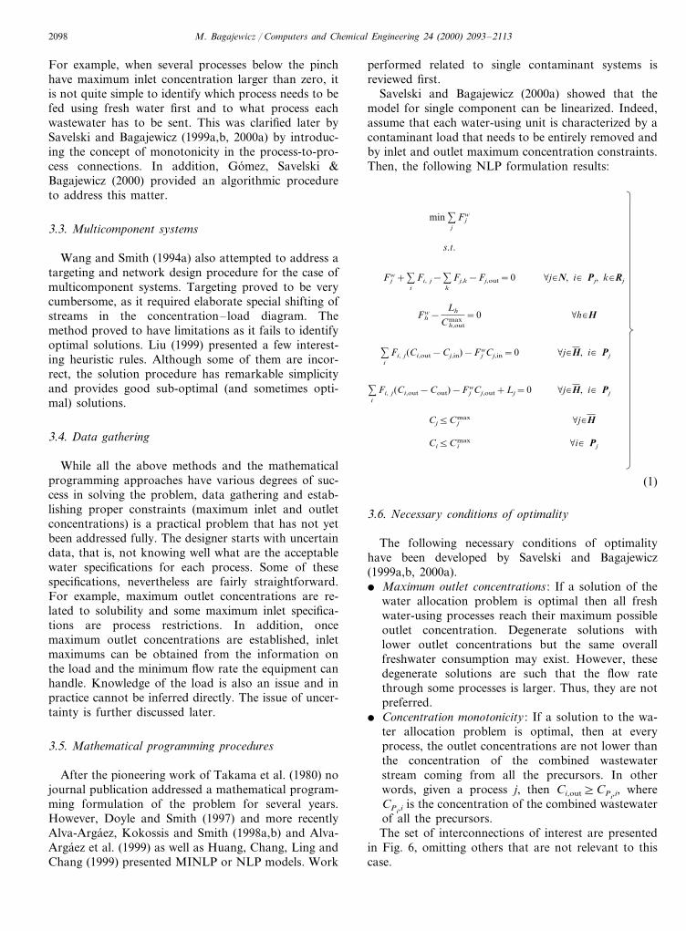
Fig. 19. Water network connections from Bagajewicz et al. (1999a,2000a).
This procedure shows that graphical procedures can-not tackle the variety of possibilities, in particular thecases when heating is required in process-to-processstreams, and cannot effectively solve the problem. Inthis formulation, the simultaneous water allocation andmaximum energy recovery heat exchanger networks aredetermined simultaneously, including the mixing ofstreams.
4. Optimal wastewater treatment
As it was outlined above, the optimal design ofwastewater systems started with Takama et al. (1980),who solved this problem in conjunction with the waterallocation problem. In this section the contributions to
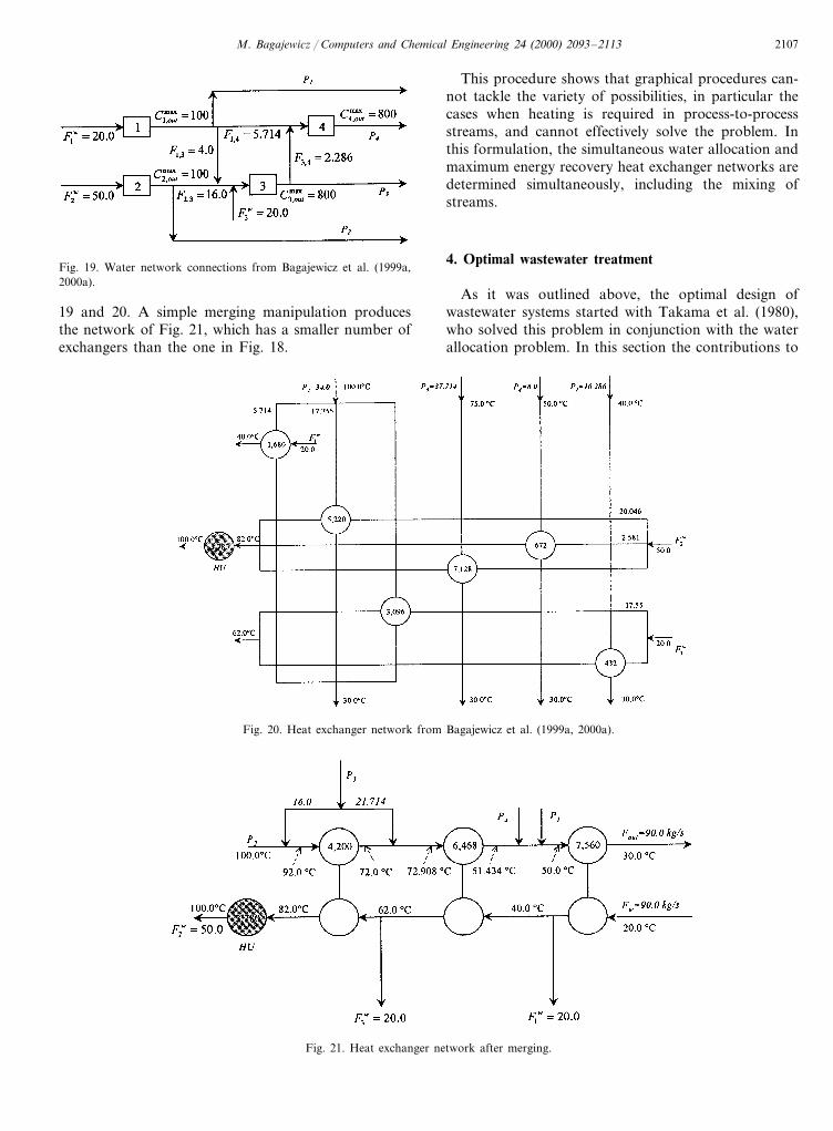
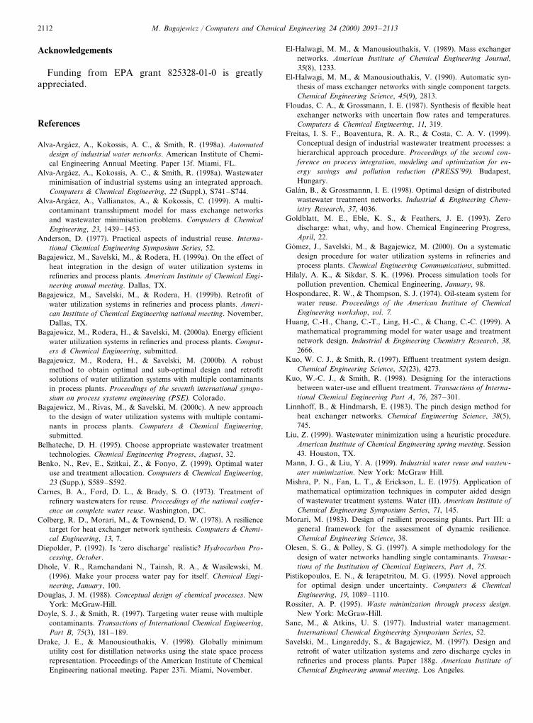
19 and 20. A simple merging manipulation producesthe network of Fig. 21, which has a smaller number ofexchangers than the one in Fig. 18.
Fig. 20. Heat exchanger network from Bagajewicz et al. (1999a, 2000a).
Fig. 21. Heat exchanger network after merging.

M. Bagajewicz / Computers and Chemical Engineering 24 (2000) 2093–21132108
Fig. 22. Optimal regeneration flow rate (following Wang & Smith,1994b).
When cost does not decrease with flow rate, Wangand Smith (1994b) identify a feasible region withinwhich the treatment flow rate line should lie. A classifi-cation of streams then follows and certain design rulesare used to obtain the network. For the case of multiplecontaminants, a network for each contaminant is de-signed and a merging procedure produces the finalunified network. A revised version of this procedurewas presented by Kuo and Smith (1997, 1998). Agraphical method that utilizes the pinch concept alongwith what the authors referred to as the wastewaterdegradation concept. The wastewater degradation takesinto account the exergy losses due to the mixing ofwastewater streams of different qualities. Then, theauthors explored several flowsheet alternatives andchoose the network with lower exergy losses. Thisapproach cannot be effectively applied to a system withmany contaminants and many wastewater streams. De-spite their value in understanding and dissecting thecomplexity of the problem, these insights have not beenproven useful in helping mathematical programmingformulations to find global optima. In view of thelimitations of this approach it is not expanded further.
Recently, Freitas, Boaventura and Costa (1999) illus-trated the use of the hierarchical design approach(Douglas, 1988) to the design of these systems. Theyconstructed a relational database and an expert systemto determine the best sequence of treatment processes.The method cannot of course, guarantee anyoptimality.
4.2. Mathematical programming procedures
In an effort to systematize a solution procedure forthis kind of problems and moving away from concep-tual design procedures into mathematical program-ming. Alva-Argaez et al. (1998a,b) modeled the entirewater management problem by means of a superstruc-ture, which leads to a MINLP problem that includessome elements not present in previous models. Themodel considers the presence of water losses, it hasbounds on water flow rates and it assumes constantremoval ratio in the wastewater treatment units. Theobjective function is non-linear and the constraintscontain the bilinear constraints that arise from compo-nent balances. No heat integration is included. Al-though the model does not guarantee optimality, theauthors claim obtaining successful results on a 12 pro-cesses and three treatment units. Galan and Grossmann(1998) also solved the effluent-treatment distributionproblem using mathematical programming. FinallyHuang et al. (1999) propose a similar NLP approach.Their contribution has some more realistic assumptionsregarding the outlet concentrations of certain processesand treatment units. They realize that, in some cases,certain units are better modeled if outlet concentrations
the design of wastewater treatment systems only isreviewed. The synergy between the two systems and theefforts to address structures such as those of Fig. 1(d),are discussed in the next section. As noted above, zeroliquid discharge solutions have not been attempteddirectly yet.
4.1. Conceptual design procedures
Wang and Smith (1994b) approached the design ofdistributed effluent treatment by a similar graphicalprocedure as presented for the water/wastewater alloca-tion problem. The authors used the same cost functionsfor the effluent treatment units as those proposed byTakama et al. (1980). The model is based on thefollowing assumptions:� Several streams available for cleaning can be split
and sent to different treatment operations. That is,no merging of these streams is assumed. However,this still implies end-of-pipe treatment, as in Fig. 1(c).
� The flow rate of water through the processes isconstant.
� The treatment units have fixed pollutant removalratio.
� Cost of treatment is assumed proportional to the flowrate of the stream to cleanup. A concentration–loaddiagram discussion justifies this simplifyingassumption.Once the problem has been put in the framework of
Concentration–load diagrams, a composite curve repre-senting all wastewater streams can be constructed. Aminimum treatment flow rate is then obtained by as-suming a fixed removal ratio. This is accomplished byrotating a treatment flow rate line around point O (Fig.22).

M. Bagajewicz / Computers and Chemical Engineering 24 (2000) 2093–2113 2109
are considered fixed, instead of fixed loads or fixedremoval ratios. Their approach is a simple extension ofthe one presented by Galan and Grossmann (1998) andhas much more merit in the type of examples solved,rather than in the solution procedure.
The solvability of these MINLP problems is at theheart of the challenge. While Alva-Argaez et al.(1998a,b), apply essentially a relaxation procedure simi-lar to the one outlined by Doyle and Smith (1997) tosolve the multicomponent water allocation problem (seeabove), Galan and Grossmann (1998) used tight linearrelaxations to obtain good starting point for an NLPsolver. At this point, it can be said that the whole areais moving towards mathematical programming meth-ods. A few researchers are still exploiting conceptualinsights to simplify solution procedures.
It is important to note that this problem does nothave minimum outlet concentrations in the outlet of thetreatment process, although maximum at both inlet andoutlet can be prescribed. In addition the removal ratiois fixed, not the load. If the load were fixed, thedistributed treatment problem would be an exact mirrorimage of the water allocation problem.
Mass exchanger network (MEN) technology wasproposed by El-Halwagi and Manousiouthakis (1990)to solve a special case of phenol removal from refinerywastewater. This approach has not yet been used incombination with other techniques.
5. Simultaneous water allocation and wastewatertreatment
Takama et al. (1980) already posed the problem as asimultaneous optimization of the overall usage of wa-ter. They however, proposed a superstructure of thetype shown in Fig. 1(c). In other words, even thoughthe water treatment is distributed, it is still centralized.Wang and Smith (1994a) showed the value of decentral-ized treatment, by discussing in detail the benefits of
partial regeneration of water in the water allocationproblem. Their approach is summarized in Fig. 23,where the slope of the target water line can be increasedbecause regeneration takes place, releasing thus theconstraint imposed by the pinch. The figure also targetswhat is the concentration at which regeneration has totake place.
Although Wang and Smith (1994a) were able toidentify regeneration opportunities for these systems,the conceptual design procedure for building the net-work has the same problems as the design withoutregeneration, especially for multicomponent. No at-tempt to address decentralized treatment was per-formed for a while. Kuo and Smith (1998) discussedbriefly the effect of the design of the water allocationproblem in the type, flow rate and quality of streamsthat feed the distributed treatment in system of the typeof Fig. 1(c).
Alva-Argaez et al. (1998a,b), Benko et al. (1999) andHuang et al. (1999), addressed the whole problem withan MINLP or NLP approach, depending on the case.The advantages of these formulations were discussedabove. While it is not clear to what extent Alva-Argaezet al. (1998a,b) used superstructures of the type shownin Fig. 1(d), it is worth pointing out that the other twopapers considered these structures in their models. Forthose that consider the issue of global optimality beingof paramount importance, it is worth pointing out thatit is not guaranteed by any of these methods. In addi-tion, it is not clear what is the maximum size ofproblems that can be solved using this approach. Itappears however, that realistic sizes can be achieved bysacrificing some nonlinearities.
6. New research opportunities
6.1. Fixed concentrations 6ersus fixed mass loads
Most of the previous work has approached the waterreuse problem by assuming that: (1) The water suppliedto a process always removes fixed loads of contami-nants; and (2) The solubility and corrosion limits canbe used to establish maximum inlet and outlet concen-tration constraints imposed on pollutants. These as-sumptions came as a necessity to represent complexprocesses through simplifying approximations, makingthe problem easier to solve.
Consider briefly a desalter unit (Fig. 24). In thisprocess water is injected (Fw) with salt concentrationCw. The raw crude comes with a certain amount ofwater (FwRi) and some salt content. The desalted crudeleaves the unit with residual water containing salt.
Using material balances, assuming that the water inthe crude and the effluent water stream have the samesalt concentration and working with a constant salt
Fig. 23. Water allocation with partial regeneration (following Wang& Smith, 1994a).

M. Bagajewicz / Computers and Chemical Engineering 24 (2000) 2093–21132110
Fig. 24. Balance on a desalter.
using operation may need to respond to differentmodels, one for each type of pollutant. This fact adds anew dimension of complexity to an already difficultmulti-contaminant problem. Some of these issues areslowly surfacing in the literature. For example, Huanget al. (1999) already refer to the constant concentrationin the outlet of some water using processes as well astreatment units.
6.2. Retrofit of existing plants
This problem needs to be focused differently than thedesign problem. As mentioned before, water reuse maybe limited by geographical, process and/ or designconstraints. Geographical constraints relate to actualdistances or interconnection limitations among unitsand become of importance when retrofitting existingsites. In such cases, connections may need to be im-posed (compulsory connections) or forbidden. The opti-mal reuse may demand connections that are technicallyimpossible to fulfill. Consequently, full water reuse maybe reduced, forcing an increase in fresh water usage.Design constraints deal with issues such as vessel, pipelines and pumps/compressors capacities as well as withcorrosion limitations. For instance, replacing fresh wa-ter with reusable wastewater usually implies an increasein flow rates and/or residence times. Such increase maynot be feasible for existing equipment. Vessels andpiping may to admit wastewater where corrosion limitsexceed the original design allowances. The optimalwater reuse scheme needs now to include other impor-tant variables such as re-piping and new pumping cost.Therefore, the objective may now depart from theminimization of fresh water consumption to include theaforementioned costs. Even though, retrofit optionshave been mentioned in several papers, (Alva-Argaez etal., 1999; Huang et al., 1999), pumping costs have notbeen included and heat integration is absent. One at-tempt to address the problem directly has been recentlydone by Bagajewicz, Savelski and Rodera (1999b) andBagajewicz et al. (2000b). The burning challenge in
removal (1−a) (independent of the flow rate and theconcentration of the incoming water), one arrives at thefollowing formula:
Fw2 Cw+FwZCw+Fw(S−RCRo−aS)+Z(S−RCRo)
−FwRiaS]0 (14)
where Z=FwRi−FwRo and S=RCRi+FwRiCwRi. Thisequation is quadratic in the water flow rate. If thecontaminant is salt: CRi=CRo=0 and the equation isslightly simplified. It becomes linear in Fw only whenfreshwater is used (Cw=0). For the case of H2S insteadof salt, one has K=CRo/Cwo and another quadraticequation is obtained. Fig. 25 shows the impact of theseequations in the typical concentration vs. load diagramused by Wang and Smith (1994a) and subsequent pa-pers. In Fig. 25(a), the diagram proposed by Wang andSmith (1994a) is shown. This contrasts with Fig. 25(b),where the load and the exit concentration vary with theflow rate used.
The problem is even richer in alternatives. In someother systems contaminants may reach solubility limits,in which case the outlet concentration is fixed and theload is, once again, variable with the flow rate. Inaddition, temperature and pressure set solubility limitsand partition coefficients. Therefore, models should beat least temperature sensitive. Moreover, since contami-nants have different solubility in water, a single water-
Fig. 25. Concentration–load diagrams.

M. Bagajewicz / Computers and Chemical Engineering 24 (2000) 2093–2113 2111
Fig. 26. The water belt.
tikopoulos and Ierapetritou (1995) are some of thepioneering papers in the area. Many others follow.
6.5. Heat integration
Even though a significant step in the direction ofheat integration has been made, there are still someunresolved matters. Systems like those shown in Fig.21 cannot be obtained automatically. A model ac-counting for the splitting of the fresh water streamand/or the merging of the wastewater streams isneeded.
6.6. Use of mass exchanger network (MEN) technology
Even though an early paper on MEN technologyaddresses directly the removal of phenol fromwastewater streams, this tool has not been exploitedto its full extent. Unfortunately, pinch operators formulticomponent systems are not easy to build, andthe use of recent novel ideas might be necessary(IDEAS; Drake and Manousiouthakis, 1998).
7. Conclusions
After the seminal paper by Takama et al. (1980),water management in process plants has grown froma humble start in the early nineties to a mature fieldwhere complex situations are analyzed and solved.Throughout the years, the field has evolved from be-ing dominated by the use of conceptual design proce-dures to the current almost exclusive use ofmathematical programming. This paper has reviewedseveral of these advances. Practical numerical chal-lenges are still apparent. Some conceptual challengesremain defiant.
8. Nomenclature
concentration at the outlet of process iCout
maximum concentration at the outlet of pro-Coutmax
cess iCin concentration at the inlet of process iC in
max maximum concentration at the inlet of pro-cess i
F jw flow rate of fresh water to process i
Fi, j flow rate of wastewater from process i toprocess j
H set of head processesLk,i contaminant load of pollutant k in process iPj set of precursor processes of process j
set of receiver processes from process jRj
Yi, j binary variable indicating whether there isflow from process i to process j
these systems is the large number of integers that theseMINLP models can have, which can induce a cumber-some integrality gap.
6.3. Water belt
This is a new concept that has been suggested as amodel to incorporate realistically plant layout consid-eration to this problem. In this model, two sets ofpiping cruise an entire battery running along all wa-ter-using units. One pipe transports make-up freshwater while the second pipe(s) collects wastewaterfrom the processes and delivers reusable wastewaterat the same time. To avoid excessive wastewaterdegradation, the second pipe may actually be a bun-dle running together and selectively receiving and dis-charging wastewater as needed. Fig. 26 illustrates theconcept of the water belt in a simplified diagram.Two processes are shown receiving fresh water andwastewater from headers and discharging it in thewastewater header. Such design presents a step aheadtowards a zero discharge cycle achievement andbreaks with the traditional process-to-process repre-sentation of this problem showing that significant sav-ings in piping can be obtained.
6.4. Uncertainty and flexibility of contaminant loads
Wastewater flow rate as well as contaminant levelscan vary. Especially in refineries, crudes carry moreheavy hydrocarbons than others, and even theamount of aromatic and naphtenic componentschanges among crudes. Heavy crudes (low API grav-ity) have a larger proportion of heavier hydrocarbonsand therefore the TBP curve is steep. This suggeststhat the design attempted should be resilient and ableto accommodate different pollutant levels.
Resiliency and flexibility have been addressed byseveral authors in the context of particular applica-tions such as heat exchangers (Colberg, Morari &Townsend, 1978; Floudas & Grossmann, 1987). Someauthors have addressed the overall plant resiliencyproblem (Morari, 1983). Recently, the problem hasbeen initiated as part of what is called ‘design withuncertainties’. Straub and Grossmann (1993) and Pis-
M. Bagajewicz / Computers and Chemical Engineering 24 (2000) 2093–21132112
Acknowledgements
Funding from EPA grant 825328-01-0 is greatlyappreciated.
References
Alva-Argaez, A., Kokossis, A. C., & Smith, R. (1998a). Automateddesign of industrial water networks. American Institute of Chemi-cal Engineering Annual Meeting. Paper 13f. Miami, FL.
Alva-Argaez, A., Kokossis, A. C., & Smith, R. (1998a). Wastewaterminimisation of industrial systems using an integrated approach.Computers & Chemical Engineering, 22 (Suppl.), S741–S744.
Alva-Argaez, A., Vallianatos, A., & Kokossis, C. (1999). A multi-contaminant transshipment model for mass exchange networksand wastewater minimisation problems. Computers & ChemicalEngineering, 23, 1439–1453.
Anderson, D. (1977). Practical aspects of industrial reuse. Interna-tional Chemical Engineering Symposium Series, 52.
Bagajewicz, M., Savelski, M., & Rodera, H. (1999a). On the effect ofheat integration in the design of water utilization systems inrefineries and process plants. American Institute of Chemical Engi-neering annual meeting. Dallas, TX.
Bagajewicz, M., Savelski, M., & Rodera, H. (1999b). Retrofit ofwater utilization systems in refineries and process plants. Ameri-can Institute of Chemical Engineering national meeting. November,Dallas, TX.
Bagajewicz, M., Rodera, H., & Savelski, M. (2000a). Energy efficientwater utilization systems in refineries and process plants. Comput-ers & Chemical Engineering, submitted.
Bagajewicz, M., Rodera, H., & Savelski, M. (2000b). A robustmethod to obtain optimal and sub-optimal design and retrofitsolutions of water utilization systems with multiple contaminantsin process plants. Proceedings of the se6enth international sympo-sium on process systems engineering (PSE). Colorado.
Bagajewicz, M., Rivas, M., & Savelski, M. (2000c). A new approachto the design of water utilization systems with multiple contami-nants in process plants. Computers & Chemical Engineering,submitted.
Belhateche, D. H. (1995). Choose appropriate wastewater treatmenttechnologies. Chemical Engineering Progress, August, 32.
Benko, N., Rev, E., Szitkai, Z., & Fonyo, Z. (1999). Optimal wateruse and treatment allocation. Computers & Chemical Engineering,23 (Supp.), S589–S592.
Carnes, B. A., Ford, D. L., & Brady, S. O. (1973). Treatment ofrefinery wastewaters for reuse. Proceedings of the national confer-ence on complete water reuse. Washington, DC.
Colberg, R. D., Morari, M., & Townsend, D. W. (1978). A resiliencetarget for heat exchanger network synthesis. Computers & Chemi-cal Engineering, 13, 7.
Diepolder, P. (1992). Is ‘zero discharge’ realistic? Hydrocarbon Pro-cessing, October.
Dhole, V. R., Ramchandani N., Tainsh, R. A., & Wasilewski, M.(1996). Make your process water pay for itself. Chemical Engi-neering, January, 100.
Douglas, J. M. (1988). Conceptual design of chemical processes. NewYork: McGraw-Hill.
Doyle, S. J., & Smith, R. (1997). Targeting water reuse with multiplecontaminants. Transactions of International Chemical Engineering,Part B, 75(3), 181–189.
Drake, J. E., & Manousiouthakis, V. (1998). Globally minimumutility cost for distillation networks using the state space processrepresentation. Proceedings of the American Institute of ChemicalEngineering national meeting. Paper 237i. Miami, November.
El-Halwagi, M. M., & Manousiouthakis, V. (1989). Mass exchangernetworks. American Institute of Chemical Engineering Journal,35(8), 1233.
El-Halwagi, M. M., & Manousiouthakis, V. (1990). Automatic syn-thesis of mass exchanger networks with single component targets.Chemical Engineering Science, 45(9), 2813.
Floudas, C. A., & Grossmann, I. E. (1987). Synthesis of flexible heatexchanger networks with uncertain flow rates and temperatures.Computers & Chemical Engineering, 11, 319.
Freitas, I. S. F., Boaventura, R. A. R., & Costa, C. A. V. (1999).Conceptual design of industrial wastewater treatment processes: ahierarchical approach procedure. Proceedings of the second con-ference on process integration, modeling and optimization for en-ergy sa6ings and pollution reduction (PRESS’99). Budapest,Hungary.
Galan, B., & Grossmannn, I. E. (1998). Optimal design of distributedwastewater treatment networks. Industrial & Engineering Chem-istry Research, 37, 4036.
Goldblatt, M. E., Eble, K. S., & Feathers, J. E. (1993). Zerodischarge: what, why, and how. Chemical Engineering Progress,April, 22.
Gomez, J., Savelski, M., & Bagajewicz, M. (2000). On a systematicdesign procedure for water utilization systems in refineries andprocess plants. Chemical Engineering Communications, submitted.
Hilaly, A. K., & Sikdar, S. K. (1996). Process simulation tools forpollution prevention. Chemical Engineering, January, 98.
Hospondarec, R. W., & Thompson, S. J. (1974). Oil-steam system forwater reuse. Proceedings of the American Institute of ChemicalEngineering workshop, 6ol. 7.
Huang, C.-H., Chang, C.-T., Ling, H.-C., & Chang, C.-C. (1999). Amathematical programming model for water usage and treatmentnetwork design. Industrial & Engineering Chemistry Research, 38,2666.
Kuo, W. C. J., & Smith, R. (1997). Effluent treatment system design.Chemical Engineering Science, 52(23), 4273.
Kuo, W.-C. J., & Smith, R. (1998). Designing for the interactionsbetween water-use and effluent treatment. Transactions of Interna-tional Chemical Engineering Part A, 76, 287–301.
Linnhoff, B., & Hindmarsh, E. (1983). The pinch design method forheat exchanger networks. Chemical Engineering Science, 38(5),745.
Liu, Z. (1999). Wastewater minimization using a heuristic procedure.American Institute of Chemical Engineering spring meeting. Session43. Houston, TX.
Mann, J. G., & Liu, Y. A. (1999). Industrial water reuse and wastew-ater minimization. New York: McGraw Hill.
Mishra, P. N., Fan, L. T., & Erickson, L. E. (1975). Application ofmathematical optimization techniques in computer aided designof wastewater treatment systems. Water (II). American Institute ofChemical Engineering Symposium Series, 71, 145.
Morari, M. (1983). Design of resilient processing plants. Part III: ageneral framework for the assessment of dynamic resilience.Chemical Engineering Science, 38.
Olesen, S. G., & Polley, S. G. (1997). A simple methodology for thedesign of water networks handling single contaminants. Transac-tions of the Institution of Chemical Engineers, Part A, 75.
Pistikopoulos, E. N., & Ierapetritou, M. G. (1995). Novel approachfor optimal design under uncertainty. Computers & ChemicalEngineering, 19, 1089–1110.
Rossiter, A. P. (1995). Waste minimization through process design.New York: McGraw-Hill.
Sane, M., & Atkins, U. S. (1977). Industrial water management.International Chemical Engineering Symposium Series, 52.
Savelski, M., Lingareddy, S., & Bagajewicz, M. (1997). Design andretrofit of water utilization systems and zero discharge cycles inrefineries and process plants. Paper 188g. American Institute ofChemical Engineering annual meeting. Los Angeles.
M. Bagajewicz / Computers and Chemical Engineering 24 (2000) 2093–2113 2113
Savelski, M., & Bagajewicz, M. (1999a). A new algorithmic designprocedure for the design of water utilization systems in refineriesand process plants. Proceedings of PRESS 99 meeting. Budapest.
Savelski, M., & Bagajewicz, M. (1999b). Watersave. A new approachto the design of water utilization systems in refineries and processplant. Proceedings of the second international conference onrefining processes, American Institute of Chemical Engineeringmeeting. Houston, TX..
Savelski, M., & Bagajewicz, M. (2000a). On the optimality conditionsof water utilization systems in process plants with single contami-nants. Chemical Engineering Science, in press.
Savelski, M., & Bagajewicz, M. (2000b). Algorithmic procedure todesign water utilization systems in refineries and process plants.Chemical Engineering Science, submitted.
Savelski, M., & Bagajewicz, M. (2000c). On The use of linear modelsfor the design of water utilization systems in refineries and processplants. Annual American Institute of Chemical Engineering meet-ing. Dallas. Chemical Engineering Research & Design, submitted.
Savelski, M., & Bagajewicz, M. (2000d). On the necessary conditionsof optimality of water utilization systems in process plants withmultiple contaminants. Chemical Engineering Science, submitted.
Savelski, M., Rivas, M., & Bagajewicz, M. (1999). A new approach tothe design of water utilization systems with multiple contaminantsin process plant. Annual American Institute of Chemical Engineer-ing meeting. Dallas, TX.
Savulescu, L. E., & Smith, R. (1998). Simultaneous energy and waterminimisation. American Institute of Chemical Engineering annualmeeting. Paper 41f. Miami, FL.
Skylov, V., & Stenzel, R. A. (1974). Reuse of wastewaters—possibil-ities and problems. Proceedings of the American Institute of Chem-ical Engineering workshop, 6ol. 7.
Sowa, C. J. (1994). Explore waste minimization via process simula-tion. Chemical Engineering Progress, No6ember, 40.
Straub, D. A., & Grossmann, I. I. (1993). Design optimization ofstochastic flexibility. Computers & Chemical Engineering, 17(4),339–354.
Takama, N., Kuriyama, T., Shiroko, K., & Umeda, T. (1980).Optimal water allocation in a petroleum refinery. Computers &Chemical Engineering, 4, 251–258.
Wang, Y. P., & Smith, R (1994a). Wastewater minimization. Chemi-cal Engineering Science, 49(7), 981.
Wang, Y. P., & Smith, R (1994b). Design of distributed effluenttreatment systems. Chemical Engineering Science, 49(18), 3127.
Wang, Y. P., & Smith, R. (1995). Wastewater Minimization withFlow rate Constraints. Transactions of the Institution of ChemicalEngineers, Part A, 73, 889–904.
Wood, R. M., Wilcox, R. J., & Grossmann, I. E. (1985). A note onminimum number of units heat exchanger network synthesis.Chemical Engineering Communications, 39, 371.
.