Embed Size (px)
Citation preview

4th International Conference on Earthquake Geotechnical Engineering
June 25-28, 2007 Paper No. 1520
A REVIEW OF PERFORMANCE BASED DESIGN PROCEDURES FOR
GRAVITY RETAINING STRUCTURES UNDER SEISMIC LOADING
Merrick TAYLOR1, Stavroula KONTOE 2, Sarada SARMA3
ABSTRACT This paper summarises the drivers for performance based design philosophy and implementation in the design of gravity retaining structures subject to seismic loading. A comparison is provided of some of the methods commonly used in practice, and other developments as presented in the literature, from simple pseudo-static limit equilibrium (PS-LE) based tools, through to fully dynamic numerical analyses capable of modelling non-linear soil behaviour. Results of a simple application of some of these PS-LE methods to a selected design problem indicate significant variability between methods, and some ambiguities with regard to the calculation of critical acceleration kc, when using various formulae in the literature with different design codes. A revised expression for the calculation of kc for these PS-LE methods is presented. A simple fully dynamic Finite Element Analysis is also considered, using the Mohr Coulomb soil model with Rayleigh damping applied to the input motion. A comparison of resulting displacements against the results of simplified methods indicates that those methods considered provide useful approaches for undertaking PBD, but careful consideration as to the respective methods limitations is required. Keywords: Retaining Wall, displacement, performance based design,
INTRODUCTION Regulatory codes and published design guides for seismic design of gravity retaining walls are typically based on simple limit equilibrium (LE) design philosophy. They typically consider the seismic load as an additional pseudo-static (PS) earth pressure. There are a number of shortcomings with this simplified design approach, but its simplicity has a number of perceived benefits. Advanced computational methods (i.e. Finite Element (FE) modelling) have been developing rapidly over the last 30 years and are nowadays a popular analysis tool. However, uncertainties related to the design input parameters (i.e. soil properties under both static and dynamic loading, seismic loading) are such that the numerical precision of advanced numerical methods may be considered with a large degree of scepticism. Hence simplified procedures are generally preferred to computational intensive numerical methods in engineering practice. On the other hand, the simple design procedures do not provide any indication of deformations occurring to the structure under the design earthquake load (i.e. the performance of the structure). In a real world earthquake scenario, movements of the soil and structure will occur under seismic loading, regardless of how over-designed the structure may be. These movements may or may not be acceptable for the performance requirements of the structure. Clearly, the difficulty arises when a critical structure is to be designed (i.e. abutment walls for a bridge designated of ‘lifeline’ importance, quay walls) where the potential economic loss of serviceability following an earthquake is unacceptably high. In these latter cases rigorous numerical modelling is required. 1 Geotechnical Engineer, ArupGeotechnics Email: [email protected] 2 Lecturer, Department of Civil & Environmental Engineering, Imperial College, London. 3 Reader, Department of Civil & Environmental Engineering, Imperial College, London.

4th International Conference on Earthquake Geotechnical Engineering
June 25-28, 2007 Paper No. 1520
In the first part of this paper a review of the available methods for seismic design of gravity walls is given. This includes the whole range of methods: from simple pseudo-static limit equilibrium (PS-LE) based tools through to fully dynamic numerical analyses. The second part of this paper details results
SUMMARY OF THE VARIOUS METHODS OF ANALYSIS The methods for performing seismic analysis of gravity walls presented in the literature are summarised here in tabular format. The methods have been divided into categories based on their mode of analysis – pseudo-static; so called pseudo-dynamic; and fully dynamic. Their derivation, limitations, advantages and shortcomings will be discussed briefly. Pseudo-static Limit Equilibrium (PS-LE) Methods (Refer Table 1) Force Based Design The design procedures in most codes fall into this category, whereby the pseudo-static seismic actions are added to the static problem as external forces, in both horizontal and vertical directions, prior to solving for limit equilibrium with a required Factor of Safety (FoS). The pseudo-static seismic loads are obtained by multiplying the mass of the failing rigid soil block by the design earthquake acceleration (usually PGA, or some fraction of it). Typically a lower FoS than for static design is considered by the design codes as being acceptable for the respective modes of failure of the wall (sliding, tilting/bearing capacity, global, structural). No indication of displacement is possible from the LE method without some further analysis beyond this method (e.g. Newmark (1965) sliding block analyses). Traditional PS-LE methods generally result in ‘over designed’ wall sizes to resist the dynamic loads calculated with the specified or required FS under seismic loading, thereby rendering the design method unsuitable from an economic or simply ‘practicable’ perspective. Assessing Seismic Displacements For the calculation of displacements of slope movement when accelerations exceed the critical acceleration for the slope mass kc, an extension of Newmark’s sliding block model (Newmark 1965) has resulted in empirical design formulae fitted to analyses of case histories of slope failures, e.g. Franklin & Chang 1977, Ambraseys & Menu 1988, and others. The Richards & Elms 1979, (R&E) empirical design formulae is derived from selected case studies within Franklin & Chang’s database suited to the anticipated small movements (< 1 m) likely to occur to retaining walls. The R&E method relies on Mononobe-Okabe (MO) (Mononobe & Matsuo 1929, Okabe 1926) dynamic active earth pressure theory to determine kc for the wall block being considered. All these methods are heavily dependent on the value of kc for the calculation of displacements, and due to their empirical nature, between each other can result in widely varying displacement values (Kramer 1996). In addition, all these methods prescribe failure to be translational and when applied to wall movements do not consider wall rotation. The rotational mode can however contribute significantly to total wall movements (Nadim & Whitman 1983). From laboratory testing (Lai and Berrill 1982) the R&E method produces reasonable results, albeit consistently over-predicting displacements slightly for translational failures. The Whitman and Liao (1985) reappraisal of the R&E method, in order to take account of the assumptions and uncertainties with the method, developed a probabilistic approach, which produces displacements generally similar to R&E, but of lower magnitude. Use in Practice: EC8 and the FHWA design guide for reinforced earth walls (Elias & al. 2001) allow for the reduction of the applied horizontal seismic coefficient based on the concept of acceptable displacements, in a similar manner to the recommendations of R&E, provided that: The wall geometry is not complex; it is not larger than 15 m; nor significant in terms of its importance post an earthquake; and that the design PGA be not greater than 0.3g. Displacements are also limited to greater than 25 mm and less than

4th International Conference on Earthquake Geotechnical Engineering
June 25-28, 2007 Paper No. 1520
300 mm (EC8) or 200 mm (FHWA) due to the fair degree of uncertainty associated with the results of such simplified analyses.
Table 1. Pseudo-static Methods for use in Seismic design of retaining structures.
Output Dynamic features modelled
Mode of Seismic Load Application
Pres
crib
ed S
oil
Beh
avio
u r
Anal
ysis
Met
hod
Load
Der
ivat
ion
Ear
th P
ress
ure
Theo
ry
Pres
crib
ed F
ailu
re
Mod
e
Pres
crib
ed P
oint
of
Act
ion
of Δ
KXE
Dis
plac
emen
ts
Forc
es
Iner
tia
Cyc
lic P
ore
Pres
sure
s Am
plifi
catio
ns
Soil
Dam
ping
Soil
Pla
stic
ity
Force based
Mononobe Okabe (MO) (c. 1929)1
P LE PGA MO T or R Not spec. N Y N N N N PP
Typical Design Code2 P LE PGA MO T or R 0.3-0.6H N Y Y N N N PPWood (1973)3 E LE PGA ET N/A 0.58H N Y Y N N N N Wood & Elms (1990)4 E-P LE PGA MO/ ET N/A 0.5H N Y Y N N N N
Displacement based Franklin & Chang (1977)5 P LE PGA/V N/A1 T N/A2 Y1 Y Y N N N PPRichards & Elms (1979)6 P LE PGA/V MO T N/A2 Y1 Y Y N N N PPWhitman & Liao (1985)7 P LE PGA/V MO T N/A2 Y1 Y Y N N N PPAmbraseys & Menu (1988)5 P LE PGA N/A1 T N/A2 Y1 Y Y N N N PP
Jibson (1994)8 P LE IA N/A1 T N/A2 Y1 Y Y N N N PPPS FE/ FD Any FE/D PGA N/A N/A N/A Y Y Y N N N PPNotes: (Refer Table 2 for Key).
1 Enlarged Coulomb wedge based on design acceleration coefficient(s). 2 E.g. NZBC B1/VM4. Some codes (FHWA, EC8) allow reduction in hor. seismic coefficient kh through
tolerable displacements, conceptually similar to Richards & Elms (1979) (R&E). 3 Derived from Elastic theory. 4 W&E (1990) Advised Interpolation of methods 2 and 3 for stiff walls with between 2% and 5% wall
deflection with respect to wall height. 5 Empirically derived from Newmark analyses of case studies. 6 Empirically derived from selected F&C results. 7 Modified R&E method taking account of uncertainty probabilistically. 8 Solution based on Newmark sliding block, using Arias Intensity instead of PGA.
Pseudo-static Finite Element/ Finite Difference Analysis The use of FE/ FD numerical methods removes the requirement to prescribe a failure mode in the analysis –as in classic LE. The use of non-linear soil models in the analysis removes the assumptions of full plastic mobilisation as required in the MO theory. The advantage of applying the seismic load as a PS force is the relatively low computational and simpler boundary condition requirements compared to full dynamic analysis. The applied PS force is however based on PGA, and will not represent the true dynamic nature of an earthquake load on the structure. It cannot therefore consider the effects of amplifications, nor soil hysteretic damping, or the development of cyclic pore pressures. Pseudo-dynamic and Dynamic Limit Equilibrium Methods (Table 2) The more complex methods (i.e. pseudo-dynamic and dynamic) seek to address the shortcomings of the PS approach to more accurately deduce wall performance. What they both have in common is the use of acceleration time histories to calculate displacements, rather than a PGA-based PS force.
4th International Conference on Earthquake Geotechnical Engineering
June 25-28, 2007 Paper No. 1520
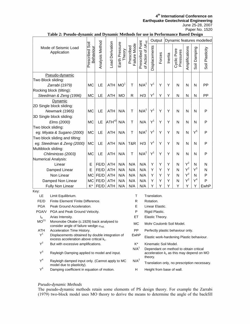
Table 2: Pseudo-dynamic and Dynamic Methods for use in Performance Based Design Output Dynamic features modelled
Mode of Seismic Load Application
Pre
scrib
ed S
oil
Beh
avio
ur
Ana
lysi
s M
etho
d
Load
Der
ivat
ion
Earth
Pre
ssur
e Th
eory
Pr
escr
ibed
Fa
ilure
Mod
e P
resc
ribed
Poi
nt
of A
ctio
n of
ΔK X
E
Dis
plac
emen
ts
Forc
es
Iner
tia
Cyc
lic P
ore
Pre
ssur
es
Ampl
ifica
tions
Soi
l Dam
ping
Soi
l Pla
stic
ity
Pseudo-dynamic Two Block sliding:
Zarrabi (1979) MC LE ATH MO1 T N/A2 Y1 Y Y N N N PP Rocking block (tilting):
Steedman & Zeng (1996) MC LE ATH MO R H/3 Y1 Y Y N N N PP Dynamic
2D Single block sliding: Newmark (1965) MC LE ATH N/A T N/A2 Y1 Y Y N N N P
3D Single block sliding: Elms (2000) MC LE ATHx3 N/A T N/A Y1 Y Y N N N P
Two block sliding: eg: Miyata & Sugano (2000) MC LE ATH N/A T N/A2 Y1 Y Y N N Y5 P
Two block sliding and tilting: eg: Steedman & Zeng (2000) MC LE ATH N/A T&R H/3 Y1 Y Y N N N P
Multiblock sliding: Chlimintzas (2003) MC LE ATH N/A T N/A2 Y1 Y Y N N N P
Numerical Analysis: Linear E FE/D ATH N/A N/A N/A Y Y Y N Y2 N N
Damped Linear E FE/D ATH N/A N/A N/A Y Y Y N Y2 Y3 N Non Linear MC FE/D ATH N/A N/A N/A Y Y Y N Y2 N P
Damped Non Linear MC FE/D ATH N/A N/A N/A Y Y Y N Y2 Y4 P Fully Non Linear K* FE/D ATH N/A N/A N/A Y Y Y Y Y Y EwhP
Key: LE Limit Equilibrium. T Translation.
FE/D Finite Element/ Finite Difference. R Rotation. PGA Peak Ground Acceleration. E Linear Elastic.
PGA/V PGA and Peak Ground Velocity. P Rigid Plastic. IA Arias Intensity. ET Elastic Theory.
MO(1) Mononobe Okabe (c.1929) back analysed to consider angle of failure wedge αAE.
MC Mohr Coulomb Soil Model.
ATH Acceleration Time History. PP Perfectly plastic behaviour only. Y1 Displacements obtained by double integration of
excess acceleration above critical kc. EwhP Elastic work-hardening Plastic behaviour.
Y2 But with excessive amplifications. K* Kinematic Soil Model.
Y3 Rayleigh Damping applied to model and input. N/A1 Dependant on method to obtain critical
acceleration kc as this may depend on MO theory.
Y4 Rayleigh damped input only. (Cannot apply to MC model due to plasticity).
N/A2 Translation only, no prescription necessary.
Y5 Damping coefficient in equation of motion. H Height from base of wall. Pseudo-dynamic Methods The pseudo-dynamic methods retain some elements of PS design theory. For example the Zarrabi (1979) two-block model uses MO theory to derive the means to determine the angle of the backfill

4th International Conference on Earthquake Geotechnical Engineering
June 25-28, 2007 Paper No. 1520
wedge, and hence the size and mass of the retained soil block, which changes incrementally throughout the analysis depending on the acceleration at any increment of time Δt during the analysis. This two-block model has been compared to the testing of Lai (1979), and found to provide better agreement than the single-block derived R&E method (Wood and Elms 1990). It does however continue to change the backfill slope angle beyond what is observed in model testing, where a stable failure plane develops and remains at a critical wedge angle during the remainder of the shaking. This perhaps helps to explain why it too tends to over-predict displacements compared to scale model testing (Simonelli & al 2000). The rocking block model of Steedman and Zeng (1996) requires the calculation of a kcr (critical rotational acceleration) coefficient, which in turn is dependant upon MO theory. It also assumes a constant location of the resultant dynamic lateral earth pressure, which is a large degree of inaccuracy for the model, as the imposed moments are sensitive to the point of action of the dynamic earth pressures. Despite this, they did manage to show reasonable agreement to scale model testing. Dynamic Methods Increasingly complex fully dynamic modified Newmark approaches have been developed to incorporate two-block sliding, sliding and tilting (2 degree of freedom blocks), and even multi-block sliding analyses incorporating mass transfer between blocks (Chlimintzas 2003). These developments are research models, and have not as yet translated to commercially available tools for engineering practice. Their limitations centre on the LE analysis method that requires a prescribed mode of failure in order to analyse the problem. For real world performance of a retaining wall, a combination of modes is often witnessed – sliding and tilting combined with the initiation of bearing failure beneath the footing is not uncommon. These models also cannot inherently consider the effects of non-linear soil behaviour, nor cyclic pore pressure generation without some additional means to reduce soil strength during the analysis. However the advantages over more complex numerical methods are that in relative terms the processing and modelling requirements are lower, whilst being more advanced models than the simple empirical formulae as used in current design practice. Dynamic Numerical Methods Dynamic numerical analysis by finite element or finite difference methods have become increasingly common in order to predict retaining wall performance under seismic loading, and the advantages are that it need not prescribe the mode of failure of the wall, and thus is capable of analysing for any combination of deformation modes simultaneously. Thus the behaviour of the structure is more correctly modelled than the LE derived approaches. Any constitutive model may be used to model soil behaviour, including kinematic hardening models that more accurately simulate the hysteretic soil behaviour under dynamic loading, with development of cyclic pore pressures, in addition to elasto-plastic behaviour below yield. These latter models do tend to be quite complicated and require many input parameters, making their calibration difficult and time consuming. For this reason the use of simpler constitutive models such as Mohr Coulomb are commonly still employed with dynamic numerical analyses albeit with modelling difficulties.
ANALYSIS DETAILS
Description of the Employed LE Model Geometry The geometry of the wall is modelled on a case history of a gravity quay wall at Kalamata Port in Greece, reported and previously analysed by Pitilakis & Moutsakis (1989). This wall was selected as, rare among case histories, it had both geometry and soil properties clearly reported. For detail of the wall performance and results of soil testing at the site, the reader should refer to the aforementioned paper. A simplified diagram of the wall is provided in figure 1, with material propertoes adopted provided in Table 3.

4th International Conference on Earthquake Geotechnical Engineering
June 25-28, 2007 Paper No. 1520
Figure 1. Simplified Model of Retaining Wall at Kalamata Port, Greece
(after Pitilakis & Moutsakis, 1989)
Table 3: Parameters adopted for pseudostatic analyses: Description Symbol Value Units Backfill Angle of Shearing Resistance φ’ 32 ° Foundation Angle of Shearing Resistance φb’ 36 ° Ratio Mobilised Angle of Shearing Resistance to Soil Shearing Resistance along concrete-soil interface:
δb/φb’ 0.67 -
Ratio for friction backface of wall δ/φ’ 1 - Unit weight of concrete blocks γconc 24 kN/m3 Unit weight of soil backfill γb 19 kN/m3 Water level (below wall crest) wl -2.1 m Peak Ground Acceleration1 PGA 0.334 g Peak Ground Velocity1 PGV 0.33 ms-1 Arias Intensity Ia 1.056 ms-1 Notes: 1. From combined Main shock and Main Aftershock records.
Peak Ground Acceleration The PGA and PGV values were obtained from the combined records of the M 5.9 main shock at Kalamata on the 13th of September 1986, and the M 4.9 aftershock of 15th September 1986. The reasons for considering the main aftershock is that, due to proximity of the aftershock epicentre being approximately 10 km closer than the main shock, the resulting record is more of an impulse load with a higher recorded PGA than for the main shock. For these seismic design calculations, 0.67*PGA was adopted as the applied kh for use in the calculation of MO dynamic earth pressure coefficients. Vertical acceleration coefficient kv was taken as 2/3*kh, and for calculation of kvc, 2/3*kc was assumed. Calculation of Critical Acceleration Parameter kc Formulae in the Literature & observed caveats. There is one definition for the critical acceleration kc, but several ways one may use to calculate kc. From the definition –“The acceleration required to initiate motion in a resting mass”, the obvious way to determine kc is to back-analyse the horizontal seismic coefficient kh at which point the wall stability FoS reduces to unity. This can be done readily using a spreadsheet with the formulae involved – either manually or using one of the inbuilt iteration routines. For hand calculation however, a formula was devised by Whitman (1979) that aims to determine kc through iteration, as kc is also the acceleration coefficient used to calculate the MO earth pressure coefficient at the point of failure. This method appears to provide quite low kc values compared to other methods:

4th International Conference on Earthquake Geotechnical Engineering
June 25-28, 2007 Paper No. 1520
⎟⎟⎠
⎞⎜⎜⎝
⎛+⎟⎟
⎠
⎞⎜⎜⎝
⎛−
=
A
AE
b
c
KCFoS
FoSk
φtan
1 (1)
Where: FoS is the Factor of safety under static loading condition (using K0 -as recommended by NAVFAC 1986 - or KA pressures? –presumably the latter is most appropriate for the relative resistance to forming the active wedge – as this is assumed by MO theory, and as used in the remainder of the expression). φb is the angle of shearing resistance of the soil/ wall interface at the base of the wall on which the wall will slide. Note that Parameter CAE =(KAE-KA)/kc. An alternative expression is provided by Kramer (1996). It too relies on M-O theory to determine the loads on the wall at occurrence of failure, and thus requires iteration to obtain kc. It includes geometry of the wall in the calculation, replacing the calculation of the static FoS as in (1).
( ) g
WPPk AEAE
bc ⎥⎦⎤
⎢⎣⎡ +−+
−′=)sin(costan θδθδ
φ (2)
Where: W is the weight of the wall, and δ is the angle of shearing resistance at the soil-wall interface behind the wall. θ is the wall backface angle. Regardless of the way the geometry is modelled (‘virtual back’ of wall θ = 0° vs. sloping θ ≈ 12.2°); fairly consistent kc values result from using this method, provided the mass of the block considered is appropriately proportioned. However, the formula contains an erratum; it is missing a tan (φ'b) term applied to the vertical component of the applied dynamic earth pressure PAE. The authors propose the following revision:
( )
gW
PPuPk wAEbAEbc ⎥⎦
⎤⎢⎣⎡ ++−′−+
+′=)cos()tan(]sin[
tanθδφθδ
φ (3)
Where u is the pore water pressure at the base of the sliding block, and Pw is the water pressure acting on the face of the block when PAE calculated with total unit weight (should the soil be sufficiently impermeable or restrained from movement). W remains the total weight of the wall block. Caveats with respect to Back-analysed kc values. One minor ambiguity is with regards to the inertia mobilised. The FHWA design guide for reinforced earth structures (Elias & al. 2001) considers that only 0.5*H of the base width is mobilised by inertia loading of the wall mass, and only 0.5* PAE (dynamic active earth pressure), as they consider it unlikely that the peak dynamic earth pressure will be in phase with the peak inertia load of the wall itself. These assumptions in turn result in a different loading configuration, and hence a different value of kc if back analysis is performed. This is in contrast to the New Zealand Building Code B1/VM4, which considers the full inertia load of the gravity wall and the full dynamic active earth pressure occurring simultaneously, as for the above iterative formulae for kc (Equations 1 – 3). For some wall geometries (where H ≈ width w) this will be a significant difference. Results For the estimation of displacement under the seismic motion that this wall was subjected to in 1986 (M 5.9 main shock and M 4.9 main aftershock), in Table 4 the various methods of pseudo-static analysis are compared against a fully dynamic Newmark sliding block analysis, for various ways of calculating kc. Equation 1 does not account for total stress condition under seismic scenario resulting in quite different kc value and hence resulting displacements. Equation 2 produces approximately the same result at Equation 3 only by co-incidence in this example; with a different geometry the results would be quite different. This analysis ignores any effects of cyclic loading on increased pore pressures beneath the foundation, reducing shear strength. If we were to take account of these factors, kc ought to reduce and increase displacements; however some empirical equations may be based on slope failures

4th International Conference on Earthquake Geotechnical Engineering
June 25-28, 2007 Paper No. 1520
with elevated pore water pressures, and this may explain the large variability between the different empirical equations presented. It is difficult to assess when the dynamic water pressure will be in phase with the inertia of the wall, and it is considered unlikely that the water body will be in phase when PGA occurs. Dynamic water pressures affecting the free face of the wall were thus ignored to simplify the analysis.
Table 4: Results of Pseudostatic Analyses varying kc calculation method. Amax = 0.334g, Vmax = 0.33 m/s
kc1 kc
1* kc2 kc
3 kc4
kc : 0.300g 0.295g 0.233g 0.294g 0.298g kc/Amax : 0.9 0.88 0.61 0.88 0.89 Method Wall Displacement in sliding (mm)
Richards & Elms 1979 4 5 12 5 5 Whitman & Liao 1985 1 1 6 1 1 Ambraseys & Menu 1988 3 4 57 4 3 Jibson 1994 4 4 11 4 4 Newmark (1965) Dynamic Analysis 1 1 7 1 1 Notes: 1. kc method by Equation 2, after Kramer (1996),
1*. kc method by Equation 3, revised equation (this paper). 2. kc method by Equation 1, after Whitman (1979), when FoS calculated using KA pressures (FoS = 2.9). 3. kc via back analysis of the PS analysis performed to NZBC B1/VM4. Inertia = full mass of wall, dynamic earth pressure = full. Does not consider vertical component of PAE. 4. kc via back analysis of the PS analysis performed to FHWA (Elias & al. 2001). Inertia over width 0.5*H, 0.5* dynamic earth pressure. Does not consider vertical component of PAE.
Description of the Employed FE Model Spatial and temporal discretisation This section details a series of 2D dynamic plane strain analyses of the quay wall illustrated in Figure 1. The adopted FE discretisation is shown in Figure 2. The mesh generated has 1784 quadrilateral elements with 8 nodes per element. The element size close to the wall of 0.5 m2 was used to capture the expected larger soil movements, with as small as 0.25 m2 at the corners of the footing. The time integration was performed with the Generalised-α method (Chung and Hulbert 1993) and with a time step Δt of 0.01s. Boundary conditions and Input Ground Motion The analyses were performed using the Domain Reduction Method (DRM) of Bielak et al (2003) in conjunction with the standard viscous boundary of Lysmer and Kuhlemeyer (1969). The DRM is a two-step sub-structuring procedure that was originally developed for seismological applications to reduce the domain that has to be modelled numerically by a change of governing variables. However, the DRM, in conjunction with a conventional absorbing boundary can also be efficiently used in the numerical modelling of geotechnical earthquake engineering problems as an advanced absorbing boundary condition (Kontoe 2006, Kontoe et al (2006)). In the first step, a 1D FE model was used to calculate and store the free-field response in terms of effective forces at various depths. In the step I analysis the excitation was applied along the bottom boundary of the 1D model, while all nodes of the same elevation on the two side boundaries were constrained to deform identically. In the step II analysis, the stored effective forces were applied to the corresponding nodes of the step II 2D model (Figure 2), which are located between the boundaries eΓ and Г. It is important to note that the fictitious boundary Г separates the computational domain into two areas Ω and +Ω . The formulation of the DRM is such that the perturbation in the external area
+Ω is only outgoing and corresponds to any deviation of the step II 2D model from the step I 1D

4th International Conference on Earthquake Geotechnical Engineering
June 25-28, 2007 Paper No. 1520
model. The standard viscous boundary was applied along the lateral boundaries of the step II model and both horizontal and vertical displacements were restricted along the bottom boundary. The N80E component (PGA=0.291g) of the Kalamata Prefecture record was incrementally applied in the horizontal direction along the bottom boundary of the FE model. Since there is no bedrock strong motion record in the vicinity of the quay wall, the surface accelerogram was scaled to 100% (MC_1.0), 70% (MC_0.7) and 50% (MC_0.5) to account for the uncertainty regarding the strong motion attenuation with depth.
zx
Ω+
Γe
Γ Ω
80.0m
71.4m
11.6m
Figure 2. Mesh discretisation (2D model).
Table 5: Soil Properties Adopted for F.E.A.
Material Type Angle of shearing
resistance φ’ (°)
Apparent cohesion c’
(kPa)
Unit Weight(kN/m3)
Young’s Modulus E0
(MPa) Concrete LE1 LE1 23.5 14000 Silty Sand (hydraulic fill) 28 0 17 100-200 Sandy Gravel (placed fill) 36 0 19.5 180 Silty Sand (in-situ) 33.5 2 18.5 200-480 Sandy Gravel (in-situ) 31.5 5 19 300-980 Conglomerate (in-situ) 32 10 20 1274 Marl (Rock) 38 20 21.5 2200-5600 1. Linear Elastic – no failure criterion modelled
Constitutive model For the 1D analysis, the soil was modelled as linear elastic material with 8% Rayleigh4 damping. For the 2D model, the soil in the internal area (Ω ) was modelled as elastic perfectly plastic Mohr – Coulomb (MC) material, while the soil in external area ( +Ω ) and the concrete were modelled as linear elastic materials with 8% Rayleigh damping. Undrained conditions were assumed in all the analyses. Table 5 presents the soil properties used for the analysis. The wall was modelled as wished in place with K0 pressures determined assuming normally consolidated conditions for the natural marine deposits and hydraulic fills. The material properties adopted for the analysis are present in Table 5. E0 and φ’ values were determined from interpreted shear wave velocity and SPT test data obtained after the earthquake. 4 The Rayleigh damping coefficients were taken as A=1.15 and B=3.092E-3 resulting in a target damping ratio of 8% for the first and the third mode of the model.

4th International Conference on Earthquake Geotechnical Engineering
June 25-28, 2007 Paper No. 1520
FE Results Ground Response A comparison of the horizontal accelerations recorded at the top (y = 0 m) and base (y = -11.35 m) of the wall (at x = 7 m) for the MC_0.7 analysis and the corresponding response spectra (Fig 4a and b respectively) provide an indication of the effect of the modelled soil on the ground response. Long period motion is largely unaffected. Predominant amplifications occurred to medium to high frequency motion (1-100Hz range), particularly at the fundamental frequencies of the wall and backfill.
-8
-6
-4
-2
0
2
4
6
8
0 1 2 3 4 5 6 7 8 9 10 11 12 13 14 15Time (s)
Acc
eler
atio
n m
/s2
Top of Wall (0m depth)
Base of Wall (11.35m depth)
0
5
10
15
20
25
30
0.01 0.1 1 10Period (s)
SA (m
/s/s
)
Top of Wall (0m depth)Base of Wall (11.35m depth)Spectral Ratio x10
Note: Arrows 1 and 2 indicate approx. the natural periods of concrete wall and backfill respectively
-6 -4 -2 0 2
Shear Strain γ (%)
-3
-2
-1
0
1
2
3
She
ar S
tress
τ (k
Pa)
(a)
0 4 8 12 16
Time (sec)
-0.2
-0.15
-0.1
-0.05
0
0.05
0.1
Hor
izon
tal d
ispl
acem
ent (
m)
MC_1.0MC_0.7MC_0.5
(b)
Figure 4: a) & b)Comparison of ground response over height of backfill for the MC_0.7 analysis. Shear stress-strain curves (c) and horizontal displacement histories (d) for three levels of input
motion recorded at the ground surface, behind the wall. Figure 4c shows the shear stress-strain curve for an integration point (x=6.66m, z=-0.394m) close to ground surface in the vicinity of the wall for the three levels of input ground motion. Clearly, the MC constitutive model fails to accurately represent the hysteretic behaviour of soil under cycling loading. The hysteretic loops should be ovate due to soils elasto-plastic behaviour below yield, not square as shown. Damping is therefore much less than in real soils, and thus amplifications predicted by the FE analyses are larger than reality. Predictably, the mobilised plastic shear strains appear highly dependant on the intensity of the applied earthquake record. In a similar way, Figure 4d compares the horizontal displacement histories for the three input records computed at a node (x=7.0m, z=0.0m) located at the ground surface in the vicinity of the wall. The displacement time histories indicate that most of the displacement that occurs during the seismic event is recoverable for the MC_0.5 analysis,
(a) (b)
1. 2.
(c) (d)

4th International Conference on Earthquake Geotechnical Engineering
June 25-28, 2007 Paper No. 1520
but not for the MC_1.0 analysis. Mode of Movement As mentioned earlier, one of the advantages of the FE method over the simple limit equilibrium procedures is that there is no need to prescribe the mode of failure of the wall, and thus is capable of analysing for any combination of deformation modes. Indeed, the plots of displacement vectors in Figure 5 obtained at different time instances from the MC_0.7 analysis illustrate both translational and rotational modes of oscillation.
(a) (b) Figure 5. Snapshots of displacement vectors showing translational mode (a) and rotational mode
(b) (MC_0.7 analysis).
DISCUSSION – CONCLUSIONS The advent of performance based design procedures for retaining walls during the late 1970s has lead to the development of methods of varying complexity for either; reducing design loads for economic design by taking account of tolerable displacements, or for assessing actual movements under a design seismic event. For reducing design loadings, PS-LE methods have been developed and whilst conservative for assessing sliding displacement, rely on a number of assumptions that may render the method un-conservative for particular wall geometries; particularly where tilting mode of failure may dominate wall motion, and cyclic pore pressures will reduce kc significantly. Varying methods of calculating kc for these PS approaches have been considered in this paper, and a revised expression is presented (Equation 3). Where wall designs deviate from the standard wall geometry used to derive these expressions, it is recommended a simple derivation be carried out to check appropriateness of the equation being adopted, as PS-LE methods are heavily dependant on the kc parameter. Dynamic numerical analysis brings with it a complex suite of requirements for modelling performance of geotechnical structures accurately. The simple FE analyses presented in this paper showed that the uncertainty regarding the input motion controls the accuracy of the numerical results. Furthermore simple elasto-plastic models like Mohr-Coulomb are generally adequate for simple FE analyses of static problems, but fail to capture important features of the soil behaviour when subjected to cyclic loading such as; stiffness degradation, hysteretic damping and plastic deformation during unloading. For these situations a kinematic hardening model currently provides the best way forward to model soil dynamics numerically, and research efforts in this direction are ongoing.
AKNOWLEDGEMENTS Merrick Taylor wishes to thank to the Hume Fellowship Trust, the New Zealand Earthquake Commission, and the New Zealand Geotechnical Society, for assisting with funding of his Masters studies at Imperial College in 2005/ 2006.
4th International Conference on Earthquake Geotechnical Engineering
June 25-28, 2007 Paper No. 1520
REFERENCES Ambraseys, N., Smit, P., Sigbjornsson, R., Suhadolc, P. and Margaris, B. Internet-Site for European
Strong-Motion Data, European Commission, Research-Directorate General, Environment and Climate Programme. 2002.[Online]: http://www.isesd.cv.ic.ac.uk/ Accessed 20 August 2006.
Ambraseys N. N., and Menu, J. M. “Earthquake-induced ground displacements,” Earthquake Engineering and Structural Dynamics, Vol. 17, pp 1-105. 1988.
Bielak J., Loukakis K., Hisada Y., and Yoshimura C. “Domain Reduction Method for Three Dimensional Earthquake Modelling in Localised Regions, Part I: Theory.” Bulletin of the Seismological Society of America, Vol. 93, No. 2, pp 817-824. 2003.
BSI, BS EN 1998-5: 2004 Eurocode 8: Design of Structures for Earthquake resistance. 2004. Chlimintzas, G. “Seismic displacements of slopes using multi-block sliding technique.” PhD Thesis.
Imperial College, London. 2003 Chung J. & Hulbert, G.M., “A time integration algorithm for structural dynamics with improved
numerical dissipation: the generalized-α method”, J. Applied Mech., Vol. 60, pp. 371–375. 1993 Dept. Building & Housing. Compliance Document New Zealand Building Code: Structure. Clause B1.
Verification Method B1/VM4 Foundations. March 2005. Elias V., Christopher B. R., and Berg R. R., Mechanically Stabilised Earth Walls and Reinforced Soil
Slopes Design and Construction Guide, FHWA-NHI-00-043. Federal Highways Administration, U.S. Dept. Transportation, Washington D.C. 2001
Elms, D.G. “Refinements to the Newmark Sliding Block Model.” Proceedings 12th World Conference on Earthquake Engineering, Auckland NZ, 2000.
FHWA, Design Guidance: Geotechnical Earthquake Engineering for Highways. Geotechnical Engineering Circular No. 3. Washington DC. May 1997.
Franklin, A.G., and Chang F.K., Earthquake resistance of rock fill dams: Report 5. “Permanent displacements of earth embankments by Newmark Sliding Block Analysis”, Misc Paper: S-71-17, Soils and Pavements Laboratory, US Army Engineers Waterways Experiment Station, Vicksburg, Mississippi. 1977
Idriss, I.M., and J.I. Sun. “SHAKE91: a computer program for conducting equivalent linear seismic response analysis of horizontally layered soil deposits. User's guide.” Dept. Civil & Environ. Eng, Univ. California, Davis, 13 pp. 1992
Jibson, R., “Predicting earthquake-induced landslide displacements using Newmark’s Sliding block analysis.” Transportation Research Record 1411, Transportation Research Board, Washington, D.C. pp. 9-17.
Kontoe S., “Development of time integration schemes and advanced boundary conditions for dynamic geotechnical analysis,” PhD thesis, Imperial College, London. 2006
Kontoe S., Zdravković L. & Potts D.M. (2006) “The Domain Reduction Method as an advanced boundary condition.” Submitted to the International Journal for Numerical and Analytical Methods in Geomechanics.
Kramer, S.L., Geotechnical Earthquake Engineering. Prentice Hall, USA. 1996 Lai, C.S., “Behaviour of Retaining Walls under Seismic Loading.” Report 79-9. Dept. of Civil Eng.,
University of Canterbury, New Zealand. 1979 Lai, C.S., and Berrill, J.B. 1979, “Shaking Table tests on a Model Retaining Wall”, Bull. NZ Nat. Soc.
Eq. Eng., Vol. 12, No. 2, June 1979. Lysmer J. & Kuhlemeyer R.L. (1969), “Finite dynamic model for infinite media”, J. Eng. Mech. Div.,
ASCE, Vol.95, No.4, pp. 859-877. Mononobe, N., and Matsuo, H., “On the determination of earth pressures during earthquakes”. Proc.
World Engineering Congress. 1929 Miyata M., and Sugano T., “Experimental and Analytical Study on the effect of input motion on the
behaviour of a caisson quay wall.” 12th World Conference on Earthquake Engineering, Auckland, NZ. 2000.
Nadim F., and Whitman R.V., “Seismically Induced Movement of Retaining Walls.” J. Geotech. Eng., Vol. 109, No. 7, ASCE pp 915-931. 1983.

4th International Conference on Earthquake Geotechnical Engineering
June 25-28, 2007 Paper No. 1520
Naval Facilities Engineering Command (NAVFAC) “Foundations and Earth structures. Design Manual DM7.02”, US Department of the Navy, Washington USA. 1986.
Naval Facilities Engineering Command (NAVFAC). “Soil Dynamics and Special Design Aspects. Design Manual DM7.03”, US Dept. of the Navy, Washington DC, USA. 1997.
Newmark, N., “Effects of earthquakes on dams and embankments”, Geotechnique, Vol. 15, No. 2, pp. 139-160. The Rankine Lecture 1965.
Okabe, S. “General Theory of earth pressures.” J. Japan Society of Civil Eng., Vol. 12, No. 1. 1926. Pitilakis, K., and Moutsakis A. “Seismic Analysis and Behaviour of Gravity Retaining Walls – The
Case of Kalamata Harbour Quay wall.” Soils and Foundations Vol. 29, (1). Japanese Society of Soil Mech. and Foundation Engineering. 1989.
Richards, R. and Elms, D., “Seismic behaviour of gravity retaining walls,” J. Geotech. Eng. Div., ASCE, Vol. 15, No. GT4, pp. 449-464. 1979.
Sarma S.K., “Earthquake Geotechnical Engineering,” MSc. (SMES) course notes. Imperial College, London. 2006
Schnabel P., Lysmer J., Seed H.B. “SHAKE, a computer program for earthquake response analysis of horizontally layered sites”. Report No. EERC 72-12, Berkeley, University of California. 1972
Seed H.B., and Whitman R.V., “Design of earth retaining structures for dynamic loads, lateral stresses in the ground and design of earth retaining structures”, J. Geotech. Eng. Div., ASCE, 1970, pp. 103-147. 1970
Seed H.B., and Idriss I.M., Ground Motion and Liquefaction during Earthquakes. Earthquake Engineering Research Institute, Berkeley, CA. 1982.
Simonelli, A.L., Carafa P., Feola A., Crewe A. J., Taylor C. A., “Retaining walls under seismic actions: Shaking table testing and numerical approaches.” Proceedings 12th World Conference on Earthquake Engineering, Auckland, NZ. 2000.
Steedman R.S., and Zeng, X. “Rotating Block Method for Seismic Displacement of Gravity Walls” Journal of Geotechnical and Geoenvironmental Engineering. ASCE. 2000.
Steedman R.S., and Zeng, X. “Rotation of Large Gravity Walls on Rigid Foundations under Seismic Loading”, In: Analysis and Design of Retaining Structures Against Earthquakes. Ed: Prakash S., ASCE 1996.
Werner, S.D., Taylor, C.E., Moore II, J.E., Walton, J.S. and Cho, S. “Risk Based Methodology for Assessing the Seismic Performance of Highway Systems.” Technical report, MCEER 00-0014, University at Buffalo, Buffalo, NY. 2000.
Whitman, R.V. “Dynamic Behaviour of Soils and Its Application to Civil Engineering Projects” Proc. 6th Pan-Am. Conf. soil mechanics and foundation engineering, Lima, Peru, 1979.
Whitman, R.V., and Liao, S., “Seismic design of retaining walls”, Misc. Paper GL-85-1, US Army Engineer Waterways Experiment Station, Vicksburg, Mississippi. 1985.
Whitman R.V. “Seismic Design and Behaviour of Gravity Retaining Wall,” In: Design and Performance of Earth Retaining Structures. Ed: Lambe P.C., Hansen L.A. ASCE. 1990
Wood J.H., “Earthquake Induced Soil Pressures on Structures”. Report No. EERL 73-05, Earthquake Engineering Research Laboratory, Calif. Inst. Tech., Pasadena. 1973.
Wood J.H., and Elms D.G. “Seismic Design of Bridge Abutments and Retaining Walls”, RRU Bulletin 84 Vol 2, Bridge Design and Research Seminar 1990. Transit New Zealand, Wellington NZ. 1990.
Zarrabi, K., “Sliding of Gravity Retaining Walls During Earthquakes Considering Vertical Acceleration and Changing Inclination of Failure Surface”, S.M. Thesis, Dept. Civil Eng., MIT. 1979.