Embed Size (px)
Citation preview
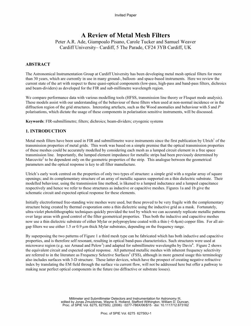
A Review of Metal Mesh Filters Peter A.R. Ade, Giampoalo Pisano, Carole Tucker and Samuel Weaver
Cardiff University– Cardiff, 5 The Parade, CF24 3YB Cardiff, UK
ABSTRACT The Astronomical Instrumentation Group at Cardiff University has been developing metal mesh optical filters for more than 30 years, which are currently in use in many ground-, balloon- and space-based instruments. Here we review the current state of the art with respect to these quasi-optical components (low-pass, high-pass and band-pass filters, dichroics and beam-dividers) as developed for the FIR and sub-millimetre wavelength region. We compare performance data with various modelling tools (HFSS, transmission line theory or Floquet mode analysis). These models assist with our understanding of the behaviour of these filters when used at non-normal incidence or in the diffraction region of the grid structures. Interesting artefacts, such as the Wood anomalies and behaviour with S and P polarisations, which dictate the usage of these components in polarisation sensitive instruments, will be discussed. Keywords: FIR-submillimetre; filters; dichroics; beam-dividers; cryogenic systems 1. INTRODUCTION Metal mesh filters have been used in FIR and submillimetre wave instruments since the first publication by Ulrich1 of the transmission properties of metal grids. This work was based on a simple premise that the optical transmission properties of these meshes could be accurately modelled by considering each mesh as a lumped circuit element in a free space transmission line. Importantly, the lumped element impedance for metallic strips had been previously determined by Marcuvitz2 to be dependent only on the geometric properties of the strip. This analogue between the geometrical parameters and the optical response is key to all filter manufacture. Ulrich’s early work centred on the properties of only two types of structure: a simple grid with a regular array of square openings; and its complementary structure of an array of metallic squares supported on a thin dielectric substrate. Their modelled behaviour, using the transmission line method, is likened to a lumped inductance and a lumped capacitance respectively and hence we refer to these structures as inductive or capacitive meshes. Figures 1a and 1b give the schematic circuit and expected optical response for these elements. Initially electroformed free-standing wire meshes were used, but these proved to be very fragile with the complementary structure being created by thermal evaporation onto a thin dielectric using the inductive grid as a mask. Fortunately, ultra-violet photolithographic techniques quickly provided the tool by which we can accurately replicate metallic patterns over large areas with good control of the filter geometrical properties. Thus both the inductive and capacitive meshes now use a thin dielectric substrate of either Mylar or polypropylene coated with a thin (~0.4µm) copper film. For all air-gap filters we use either 1.5 or 0.9 µm thick Mylar substrates, depending on the frequency range. By superposing the two patterns of Figure 1 a third mesh type can be fabricated which has both inductive and capacitive properties, and is therefore self resonant, resulting in optical band-pass characteristics. Such structures were used at microwave region (e.g. see Arnaud and Pelow3) and adapted for submillimetre wavelengths by Davis4. Figure 2 shows the equivalent circuit and expected optical response. All patterned metallic meshes with inherent frequency selectivity are referred to in the literature as Frequency Selective Surfaces5 (FSS), although in more general usage this terminology also includes surfaces with 3-D structure. These latter devices, which have the prospect of creating negative refractive index by translating the EM field through the surface via current flow, will not be addressed here but offer a pathway to making near perfect optical components in the future (no diffractive or substrate losses).
Invited Paper
Millimeter and Submillimeter Detectors and Instrumentation for Astronomy III, edited by Jonas Zmuidzinas, Wayne S. Holland, Stafford Withington, William D. Duncan, Proc. of SPIE Vol. 6275, 62750U, (2006) · 0277-786X/06/$15 · doi: 10.1117/12.673162
Proc. of SPIE Vol. 6275 62750U-1
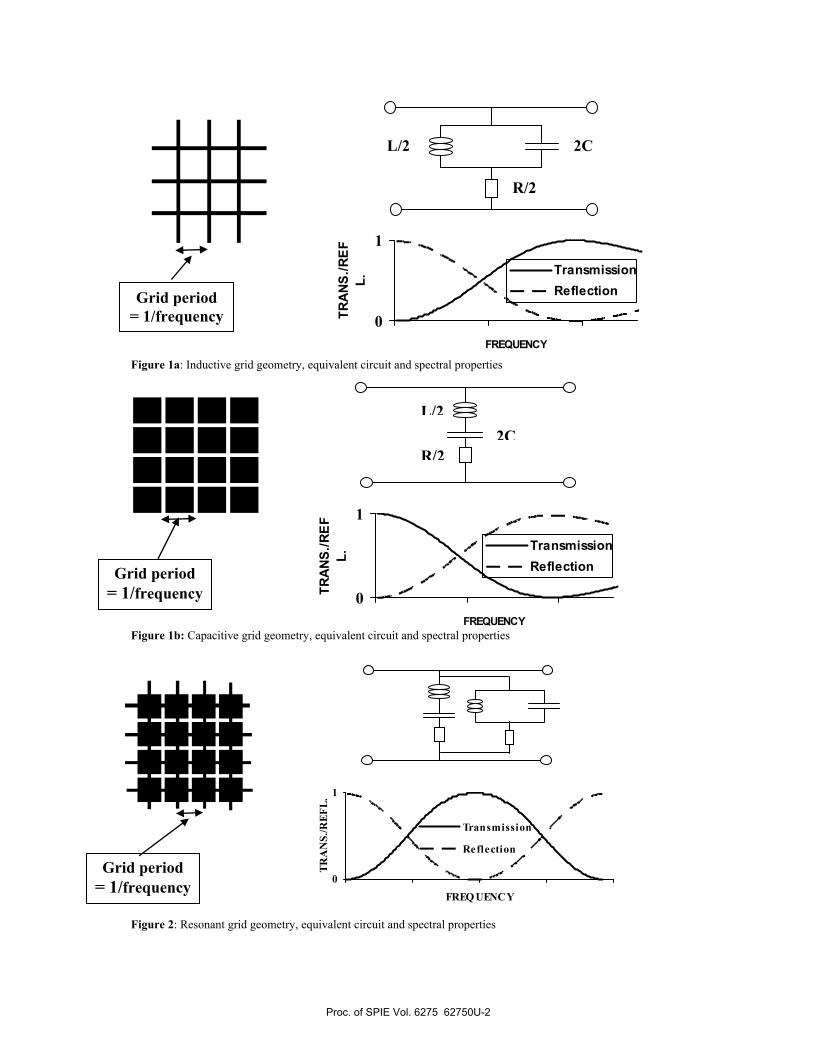
Figure 1a: Inductive grid geometry, equivalent circuit and spectral properties
Figure 1b: Capacitive grid geometry, equivalent circuit and spectral properties
Figure 2: Resonant grid geometry, equivalent circuit and spectral properties
Grid period = 1/frequency
L/2 2C
R/2
0
1
FREQUENCYTR
ANS
./RE
FL.
TransmissionReflection
Grid period = 1/frequency
2CL/2
R/2
0
1
FREQUENCY
TRA
NS.
/RE
FL.
TransmissionReflection
Grid period = 1/frequency
0
1
FREQ UENCY
TRA
NS.
/REF
L.
Transmission
Reflection
Proc. of SPIE Vol. 6275 62750U-2
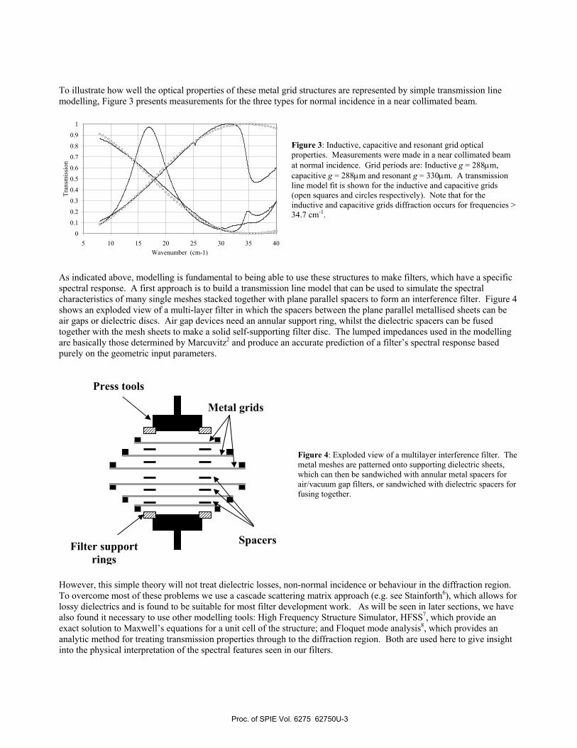
To illustrate how well the optical properties of these metal grid structures are represented by simple transmission line modelling, Figure 3 presents measurements for the three types for normal incidence in a near collimated beam.
Figure 3: Inductive, capacitive and resonant grid optical properties. Measurements were made in a near collimated beam at normal incidence. Grid periods are: Inductive g = 288µm, capacitive g = 288µm and resonant g = 330µm. A transmission line model fit is shown for the inductive and capacitive grids (open squares and circles respectively). Note that for the inductive and capacitive grids diffraction occurs for frequencies > 34.7 cm-1.
As indicated above, modelling is fundamental to being able to use these structures to make filters, which have a specific spectral response. A first approach is to build a transmission line model that can be used to simulate the spectral characteristics of many single meshes stacked together with plane parallel spacers to form an interference filter. Figure 4 shows an exploded view of a multi-layer filter in which the spacers between the plane parallel metallised sheets can be air gaps or dielectric discs. Air gap devices need an annular support ring, whilst the dielectric spacers can be fused together with the mesh sheets to make a solid self-supporting filter disc. The lumped impedances used in the modelling are basically those determined by Marcuvitz2 and produce an accurate prediction of a filter’s spectral response based purely on the geometric input parameters.
Figure 4: Exploded view of a multilayer interference filter. The metal meshes are patterned onto supporting dielectric sheets, which can then be sandwiched with annular metal spacers for air/vacuum gap filters, or sandwiched with dielectric spacers for fusing together.
However, this simple theory will not treat dielectric losses, non-normal incidence or behaviour in the diffraction region. To overcome most of these problems we use a cascade scattering matrix approach (e.g. see Stainforth6), which allows for lossy dielectrics and is found to be suitable for most filter development work. As will be seen in later sections, we have also found it necessary to use other modelling tools: High Frequency Structure Simulator, HFSS7, which provide an exact solution to Maxwell’s equations for a unit cell of the structure; and Floquet mode analysis8, which provides an analytic method for treating transmission properties through to the diffraction region. Both are used here to give insight into the physical interpretation of the spectral features seen in our filters.
Press tools
Metal grids
Spacers Filter support rings
0
0.1
0.2
0.3
0.4
0.5
0.6
0.7
0.8
0.9
1
5 10 15 20 25 30 35 40Wavenumber (cm-1)
Tran
smis
sion
Proc. of SPIE Vol. 6275 62750U-3
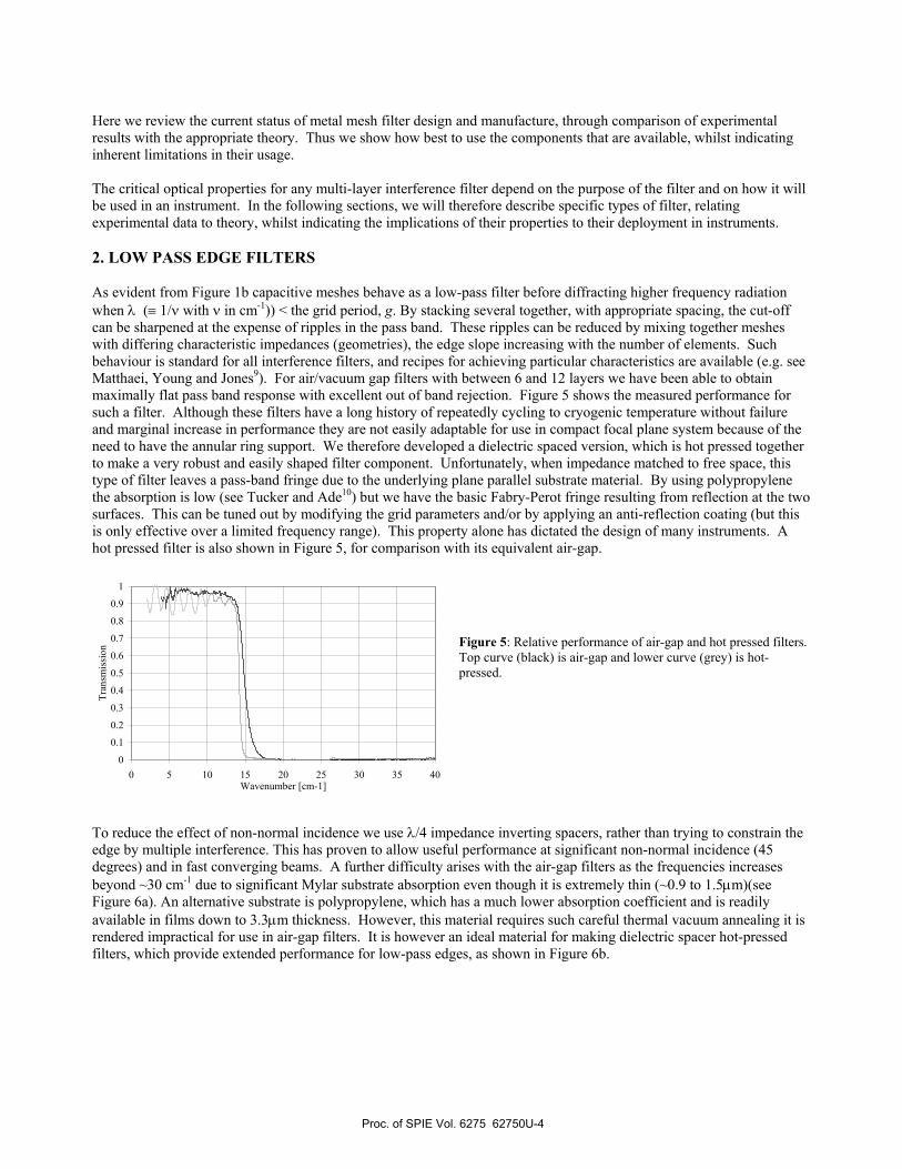
Here we review the current status of metal mesh filter design and manufacture, through comparison of experimental results with the appropriate theory. Thus we show how best to use the components that are available, whilst indicating inherent limitations in their usage. The critical optical properties for any multi-layer interference filter depend on the purpose of the filter and on how it will be used in an instrument. In the following sections, we will therefore describe specific types of filter, relating experimental data to theory, whilst indicating the implications of their properties to their deployment in instruments. 2. LOW PASS EDGE FILTERS As evident from Figure 1b capacitive meshes behave as a low-pass filter before diffracting higher frequency radiation when λ (≡ 1/ν with ν in cm-1)) < the grid period, g. By stacking several together, with appropriate spacing, the cut-off can be sharpened at the expense of ripples in the pass band. These ripples can be reduced by mixing together meshes with differing characteristic impedances (geometries), the edge slope increasing with the number of elements. Such behaviour is standard for all interference filters, and recipes for achieving particular characteristics are available (e.g. see Matthaei, Young and Jones9). For air/vacuum gap filters with between 6 and 12 layers we have been able to obtain maximally flat pass band response with excellent out of band rejection. Figure 5 shows the measured performance for such a filter. Although these filters have a long history of repeatedly cycling to cryogenic temperature without failure and marginal increase in performance they are not easily adaptable for use in compact focal plane system because of the need to have the annular ring support. We therefore developed a dielectric spaced version, which is hot pressed together to make a very robust and easily shaped filter component. Unfortunately, when impedance matched to free space, this type of filter leaves a pass-band fringe due to the underlying plane parallel substrate material. By using polypropylene the absorption is low (see Tucker and Ade10) but we have the basic Fabry-Perot fringe resulting from reflection at the two surfaces. This can be tuned out by modifying the grid parameters and/or by applying an anti-reflection coating (but this is only effective over a limited frequency range). This property alone has dictated the design of many instruments. A hot pressed filter is also shown in Figure 5, for comparison with its equivalent air-gap.
Figure 5: Relative performance of air-gap and hot pressed filters. Top curve (black) is air-gap and lower curve (grey) is hot-pressed.
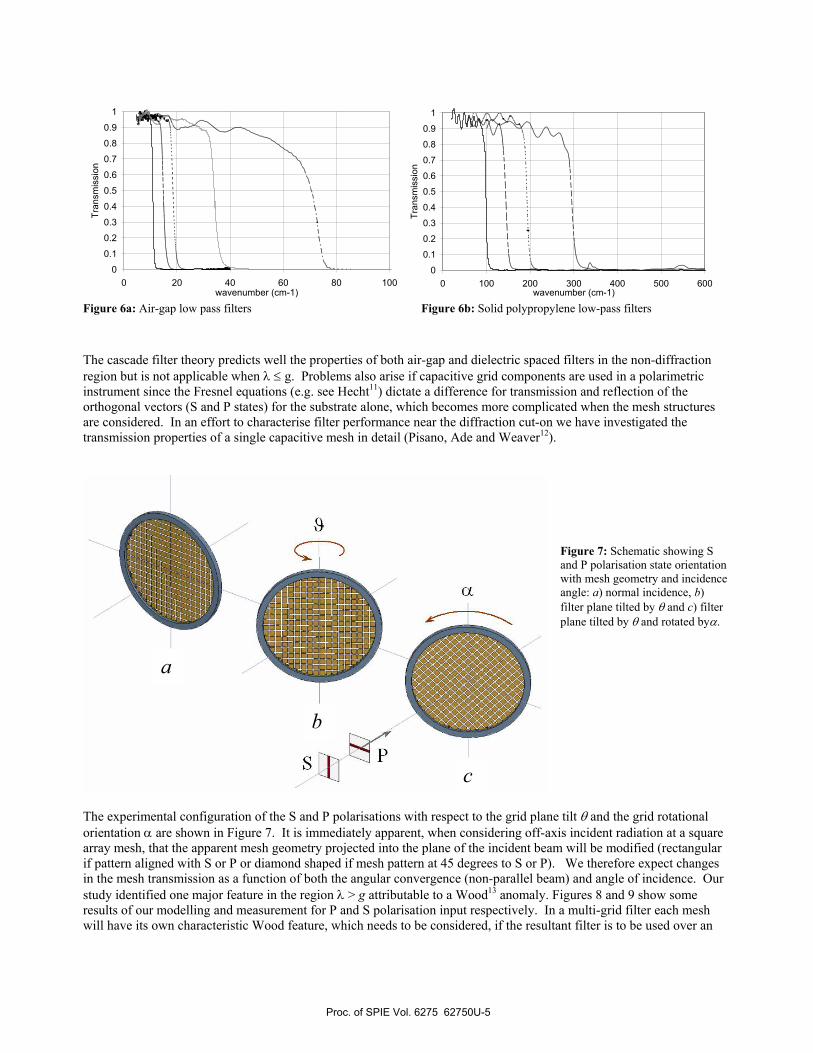
To reduce the effect of non-normal incidence we use λ/4 impedance inverting spacers, rather than trying to constrain the edge by multiple interference. This has proven to allow useful performance at significant non-normal incidence (45 degrees) and in fast converging beams. A further difficulty arises with the air-gap filters as the frequencies increases beyond ~30 cm-1 due to significant Mylar substrate absorption even though it is extremely thin (~0.9 to 1.5µm)(see Figure 6a). An alternative substrate is polypropylene, which has a much lower absorption coefficient and is readily available in films down to 3.3µm thickness. However, this material requires such careful thermal vacuum annealing it is rendered impractical for use in air-gap filters. It is however an ideal material for making dielectric spacer hot-pressed filters, which provide extended performance for low-pass edges, as shown in Figure 6b.
0
0.1
0.2
0.3
0.4
0.5
0.6
0.7
0.8
0.9
1
0 5 10 15 20 25 30 35 40Wavenumber [cm-1]
Tran
smis
sion
Proc. of SPIE Vol. 6275 62750U-4
&Ca
0
0.1
0.2
0.3
0.4
0.5
0.6
0.7
0.8
0.9
1
0 20 40 60 80 100wavenumber (cm-1)
Tran
smis
sion
0
0.1
0.2
0.3
0.4
0.5
0.6
0.7
0.8
0.9
1
0 100 200 300 400 500 600wavenumber (cm-1)
Tran
smis
sion
Figure 6a: Air-gap low pass filters Figure 6b: Solid polypropylene low-pass filters The cascade filter theory predicts well the properties of both air-gap and dielectric spaced filters in the non-diffraction region but is not applicable when λ ≤ g. Problems also arise if capacitive grid components are used in a polarimetric instrument since the Fresnel equations (e.g. see Hecht11) dictate a difference for transmission and reflection of the orthogonal vectors (S and P states) for the substrate alone, which becomes more complicated when the mesh structures are considered. In an effort to characterise filter performance near the diffraction cut-on we have investigated the transmission properties of a single capacitive mesh in detail (Pisano, Ade and Weaver12).
Figure 7: Schematic showing S and P polarisation state orientation with mesh geometry and incidence angle: a) normal incidence, b) filter plane tilted by θ and c) filter plane tilted by θ and rotated byα.
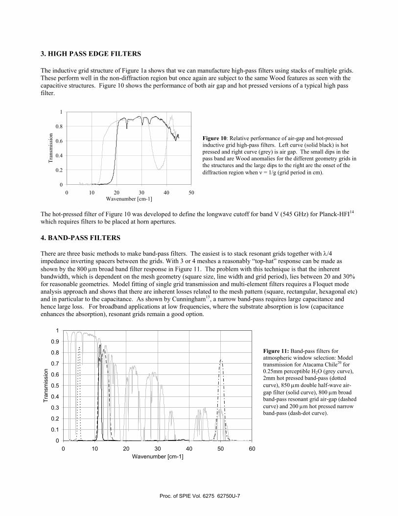
The experimental configuration of the S and P polarisations with respect to the grid plane tilt θ and the grid rotational orientation α are shown in Figure 7. It is immediately apparent, when considering off-axis incident radiation at a square array mesh, that the apparent mesh geometry projected into the plane of the incident beam will be modified (rectangular if pattern aligned with S or P or diamond shaped if mesh pattern at 45 degrees to S or P). We therefore expect changes in the mesh transmission as a function of both the angular convergence (non-parallel beam) and angle of incidence. Our study identified one major feature in the region λ > g attributable to a Wood13 anomaly. Figures 8 and 9 show some results of our modelling and measurement for P and S polarisation input respectively. In a multi-grid filter each mesh will have its own characteristic Wood feature, which needs to be considered, if the resultant filter is to be used over an
a
b
c
Proc. of SPIE Vol. 6275 62750U-5
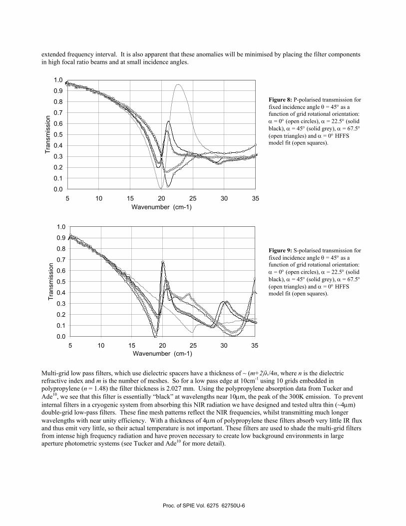
extended frequency interval. It is also apparent that these anomalies will be minimised by placing the filter components in high focal ratio beams and at small incidence angles.
Figure 8: P-polarised transmission for fixed incidence angle θ = 45° as a function of grid rotational orientation: α = 0° (open circles), α = 22.5° (solid black), α = 45° (solid grey), α = 67.5° (open triangles) and α = 0° HFFS model fit (open squares). Figure 9: S-polarised transmission for fixed incidence angle θ = 45° as a function of grid rotational orientation: α = 0° (open circles), α = 22.5° (solid black), α = 45° (solid grey), α = 67.5° (open triangles) and α = 0° HFFS model fit (open squares).
Multi-grid low pass filters, which use dielectric spacers have a thickness of ~ (m+2)λ/4n, where n is the dielectric refractive index and m is the number of meshes. So for a low pass edge at 10cm-1 using 10 grids embedded in polypropylene (n = 1.48) the filter thickness is 2.027 mm. Using the polypropylene absorption data from Tucker and Ade10, we see that this filter is essentially “black” at wavelengths near 10µm, the peak of the 300K emission. To prevent internal filters in a cryogenic system from absorbing this NIR radiation we have designed and tested ultra thin (~4µm) double-grid low-pass filters. These fine mesh patterns reflect the NIR frequencies, whilst transmitting much longer wavelengths with near unity efficiency. With a thickness of 4µm of polypropylene these filters absorb very little IR flux and thus emit very little, so their actual temperature is not important. These filters are used to shade the multi-grid filters from intense high frequency radiation and have proven necessary to create low background environments in large aperture photometric systems (see Tucker and Ade10 for more detail).
0.0
0.1
0.2
0.3
0.4
0.5
0.6
0.7
0.8
0.9
1.0
5 10 15 20 25 30 35Wavenumber (cm-1)
Tran
smis
sion
0.0
0.1
0.2
0.3
0.4
0.5
0.6
0.7
0.8
0.9
1.0
5 10 15 20 25 30 35Wavenumber (cm-1)
Tran
smis
sion
Proc. of SPIE Vol. 6275 62750U-6
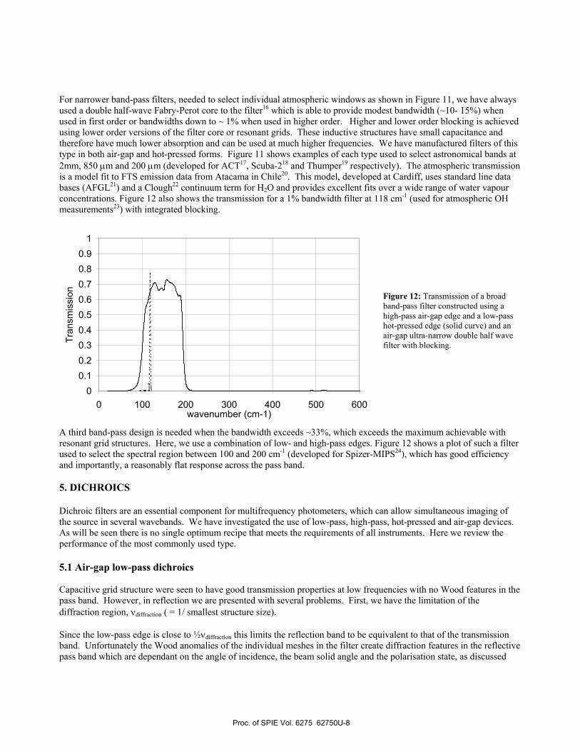
3. HIGH PASS EDGE FILTERS The inductive grid structure of Figure 1a shows that we can manufacture high-pass filters using stacks of multiple grids. These perform well in the non-diffraction region but once again are subject to the same Wood features as seen with the capacitive structures. Figure 10 shows the performance of both air gap and hot pressed versions of a typical high pass filter.
Figure 10: Relative performance of air-gap and hot-pressed inductive grid high-pass filters. Left curve (solid black) is hot pressed and right curve (grey) is air gap. The small dips in the pass band are Wood anomalies for the different geometry grids in the structures and the large dips to the right are the onset of the diffraction region when ν = 1/g (grid period in cm).
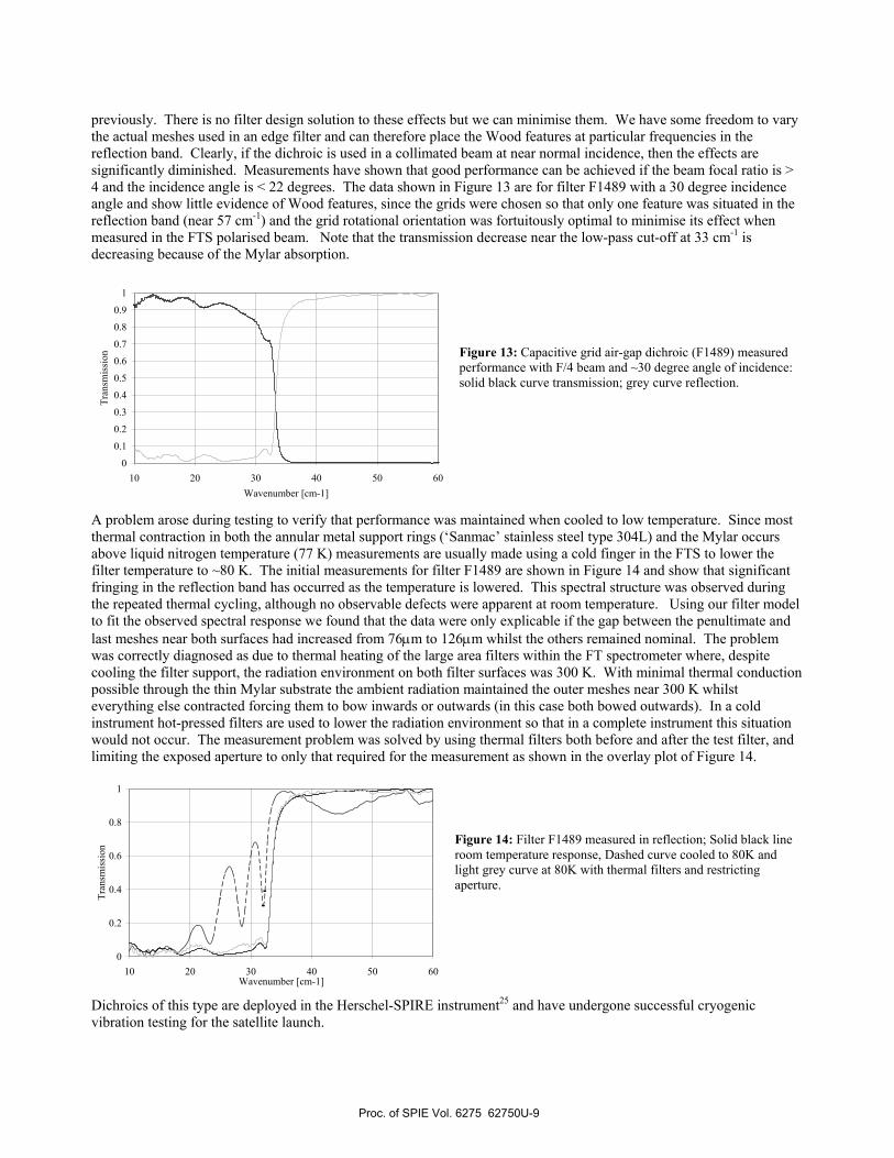
The hot-pressed filter of Figure 10 was developed to define the longwave cutoff for band V (545 GHz) for Planck-HFI14 which requires filters to be placed at horn apertures. 4. BAND-PASS FILTERS There are three basic methods to make band-pass filters. The easiest is to stack resonant grids together with λ/4 impedance inverting spacers between the grids. With 3 or 4 meshes a reasonably “top-hat” response can be made as shown by the 800 µm broad band filter response in Figure 11. The problem with this technique is that the inherent bandwidth, which is dependent on the mesh geometry (square size, line width and grid period), lies between 20 and 30% for reasonable geometries. Model fitting of single grid transmission and multi-element filters requires a Floquet mode analysis approach and shows that there are inherent losses related to the mesh pattern (square, rectangular, hexagonal etc) and in particular to the capacitance. As shown by Cunningham15, a narrow band-pass requires large capacitance and hence large loss. For broadband applications at low frequencies, where the substrate absorption is low (capacitance enhances the absorption), resonant grids remain a good option.
Figure 11: Band-pass filters for atmospheric window selection: Model transmission for Atacama Chile20 for 0.25mm perceptible H2O (grey curve), 2mm hot pressed band-pass (dotted curve), 850 µm double half-wave air-gap filter (solid curve), 800 µm broad band-pass resonant grid air-gap (dashed curve) and 200 µm hot pressed narrow band-pass (dash-dot curve).
0
0.2
0.4
0.6
0.8
1
0 10 20 30 40 50Wavenumber [cm-1]
Tran
smis
sion
0
0.1
0.2
0.3
0.4
0.5
0.6
0.7
0.8
0.9
1
0 10 20 30 40 50 60Wavenumber [cm-1]
Tran
smis
sion
Proc. of SPIE Vol. 6275 62750U-7
For narrower band-pass filters, needed to select individual atmospheric windows as shown in Figure 11, we have always used a double half-wave Fabry-Perot core to the filter16 which is able to provide modest bandwidth (~10- 15%) when used in first order or bandwidths down to ~ 1% when used in higher order. Higher and lower order blocking is achieved using lower order versions of the filter core or resonant grids. These inductive structures have small capacitance and therefore have much lower absorption and can be used at much higher frequencies. We have manufactured filters of this type in both air-gap and hot-pressed forms. Figure 11 shows examples of each type used to select astronomical bands at 2mm, 850 µm and 200 µm (developed for ACT17, Scuba-218 and Thumper19 respectively). The atmospheric transmission is a model fit to FTS emission data from Atacama in Chile20. This model, developed at Cardiff, uses standard line data bases (AFGL21) and a Clough22 continuum term for H2O and provides excellent fits over a wide range of water vapour concentrations. Figure 12 also shows the transmission for a 1% bandwidth filter at 118 cm-1 (used for atmospheric OH measurements23) with integrated blocking.
Figure 12: Transmission of a broad band-pass filter constructed using a high-pass air-gap edge and a low-pass hot-pressed edge (solid curve) and an air-gap ultra-narrow double half wave filter with blocking.
A third band-pass design is needed when the bandwidth exceeds ~33%, which exceeds the maximum achievable with resonant grid structures. Here, we use a combination of low- and high-pass edges. Figure 12 shows a plot of such a filter used to select the spectral region between 100 and 200 cm-1 (developed for Spizer-MIPS24), which has good efficiency and importantly, a reasonably flat response across the pass band. 5. DICHROICS Dichroic filters are an essential component for multifrequency photometers, which can allow simultaneous imaging of the source in several wavebands. We have investigated the use of low-pass, high-pass, hot-pressed and air-gap devices. As will be seen there is no single optimum recipe that meets the requirements of all instruments. Here we review the performance of the most commonly used type. 5.1 Air-gap low-pass dichroics Capacitive grid structure were seen to have good transmission properties at low frequencies with no Wood features in the pass band. However, in reflection we are presented with several problems. First, we have the limitation of the diffraction region, νdiffraction ( = 1/ smallest structure size). Since the low-pass edge is close to ½νdiffraction this limits the reflection band to be equivalent to that of the transmission band. Unfortunately the Wood anomalies of the individual meshes in the filter create diffraction features in the reflective pass band which are dependant on the angle of incidence, the beam solid angle and the polarisation state, as discussed
00.10.20.30.40.50.60.70.80.9
1
0 100 200 300 400 500 600wavenumber (cm-1)
Tran
smis
sion
Proc. of SPIE Vol. 6275 62750U-8
previously. There is no filter design solution to these effects but we can minimise them. We have some freedom to vary the actual meshes used in an edge filter and can therefore place the Wood features at particular frequencies in the reflection band. Clearly, if the dichroic is used in a collimated beam at near normal incidence, then the effects are significantly diminished. Measurements have shown that good performance can be achieved if the beam focal ratio is > 4 and the incidence angle is < 22 degrees. The data shown in Figure 13 are for filter F1489 with a 30 degree incidence angle and show little evidence of Wood features, since the grids were chosen so that only one feature was situated in the reflection band (near 57 cm-1) and the grid rotational orientation was fortuitously optimal to minimise its effect when measured in the FTS polarised beam. Note that the transmission decrease near the low-pass cut-off at 33 cm-1 is decreasing because of the Mylar absorption.
Figure 13: Capacitive grid air-gap dichroic (F1489) measured performance with F/4 beam and ~30 degree angle of incidence: solid black curve transmission; grey curve reflection.
A problem arose during testing to verify that performance was maintained when cooled to low temperature. Since most thermal contraction in both the annular metal support rings (‘Sanmac’ stainless steel type 304L) and the Mylar occurs above liquid nitrogen temperature (77 K) measurements are usually made using a cold finger in the FTS to lower the filter temperature to ~80 K. The initial measurements for filter F1489 are shown in Figure 14 and show that significant fringing in the reflection band has occurred as the temperature is lowered. This spectral structure was observed during the repeated thermal cycling, although no observable defects were apparent at room temperature. Using our filter model to fit the observed spectral response we found that the data were only explicable if the gap between the penultimate and last meshes near both surfaces had increased from 76µm to 126µm whilst the others remained nominal. The problem was correctly diagnosed as due to thermal heating of the large area filters within the FT spectrometer where, despite cooling the filter support, the radiation environment on both filter surfaces was 300 K. With minimal thermal conduction possible through the thin Mylar substrate the ambient radiation maintained the outer meshes near 300 K whilst everything else contracted forcing them to bow inwards or outwards (in this case both bowed outwards). In a cold instrument hot-pressed filters are used to lower the radiation environment so that in a complete instrument this situation would not occur. The measurement problem was solved by using thermal filters both before and after the test filter, and limiting the exposed aperture to only that required for the measurement as shown in the overlay plot of Figure 14.
Figure 14: Filter F1489 measured in reflection; Solid black line room temperature response, Dashed curve cooled to 80K and light grey curve at 80K with thermal filters and restricting aperture.
Dichroics of this type are deployed in the Herschel-SPIRE instrument25 and have undergone successful cryogenic vibration testing for the satellite launch.
0
0.1
0.2
0.3
0.4
0.5
0.6
0.7
0.8
0.9
1
10 20 30 40 50 60Wavenumber [cm-1]
Tran
smis
sion
0
0.2
0.4
0.6
0.8
1
10 20 30 40 50 60Wavenumber [cm-1]
Tran
smis
sion
Proc. of SPIE Vol. 6275 62750U-9
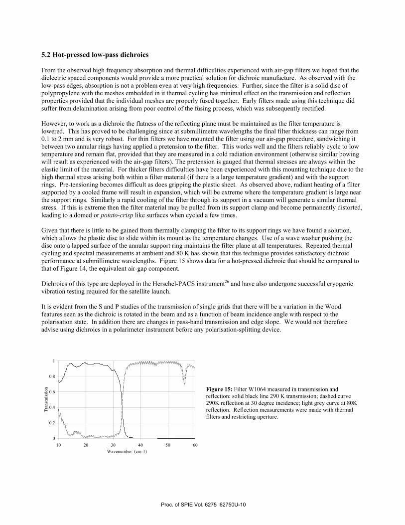
5.2 Hot-pressed low-pass dichroics From the observed high frequency absorption and thermal difficulties experienced with air-gap filters we hoped that the dielectric spaced components would provide a more practical solution for dichroic manufacture. As observed with the low-pass edges, absorption is not a problem even at very high frequencies. Further, since the filter is a solid disc of polypropylene with the meshes embedded in it thermal cycling has minimal effect on the transmission and reflection properties provided that the individual meshes are properly fused together. Early filters made using this technique did suffer from delamination arising from poor control of the fusing process, which was subsequently rectified. However, to work as a dichroic the flatness of the reflecting plane must be maintained as the filter temperature is lowered. This has proved to be challenging since at submillimetre wavelengths the final filter thickness can range from 0.1 to 2 mm and is very robust. For thin filters we have mounted the filter using our air-gap procedure, sandwiching it between two annular rings having applied a pretension to the filter. This works well and the filters reliably cycle to low temperature and remain flat, provided that they are measured in a cold radiation environment (otherwise similar bowing will result as experienced with the air-gap filters). The pretension is gauged that thermal stresses are always within the elastic limit of the material. For thicker filters difficulties have been experienced with this mounting technique due to the high thermal stress arising both within a filter material (if there is a large temperature gradient) and with the support rings. Pre-tensioning becomes difficult as does gripping the plastic sheet. As observed above, radiant heating of a filter supported by a cooled frame will result in expansion, which will be extreme where the temperature gradient is large near the support rings. Similarly a rapid cooling of the filter through its support in a vacuum will generate a similar thermal stress. If this is extreme then the filter material may be pulled from its support clamp and become permanently distorted, leading to a domed or potato-crisp like surfaces when cycled a few times. Given that there is little to be gained from thermally clamping the filter to its support rings we have found a solution, which allows the plastic disc to slide within its mount as the temperature changes. Use of a wave washer pushing the disc onto a lapped surface of the annular support ring maintains the filter plane at all temperatures. Repeated thermal cycling and spectral measurements at ambient and 80 K has shown that this technique provides satisfactory dichroic performance at submillimetre wavelengths. Figure 15 shows data for a hot-pressed dichroic that should be compared to that of Figure 14, the equivalent air-gap component. Dichroics of this type are deployed in the Herschel-PACS instrument26 and have also undergone successful cryogenic vibration testing required for the satellite launch. It is evident from the S and P studies of the transmission of single grids that there will be a variation in the Wood features seen as the dichroic is rotated in the beam and as a function of beam incidence angle with respect to the polarisation state. In addition there are changes in pass-band transmission and edge slope. We would not therefore advise using dichroics in a polarimeter instrument before any polarisation-splitting device.
Figure 15: Filter W1064 measured in transmission and reflection: solid black line 290 K transmission; dashed curve 290K reflection at 30 degree incidence; light grey curve at 80K reflection. Reflection measurements were made with thermal filters and restricting aperture.
0
0.2
0.4
0.6
0.8
1
10 20 30 40 50 60Wavenumber (cm-1)
Tran
smis
sion
Proc. of SPIE Vol. 6275 62750U-10
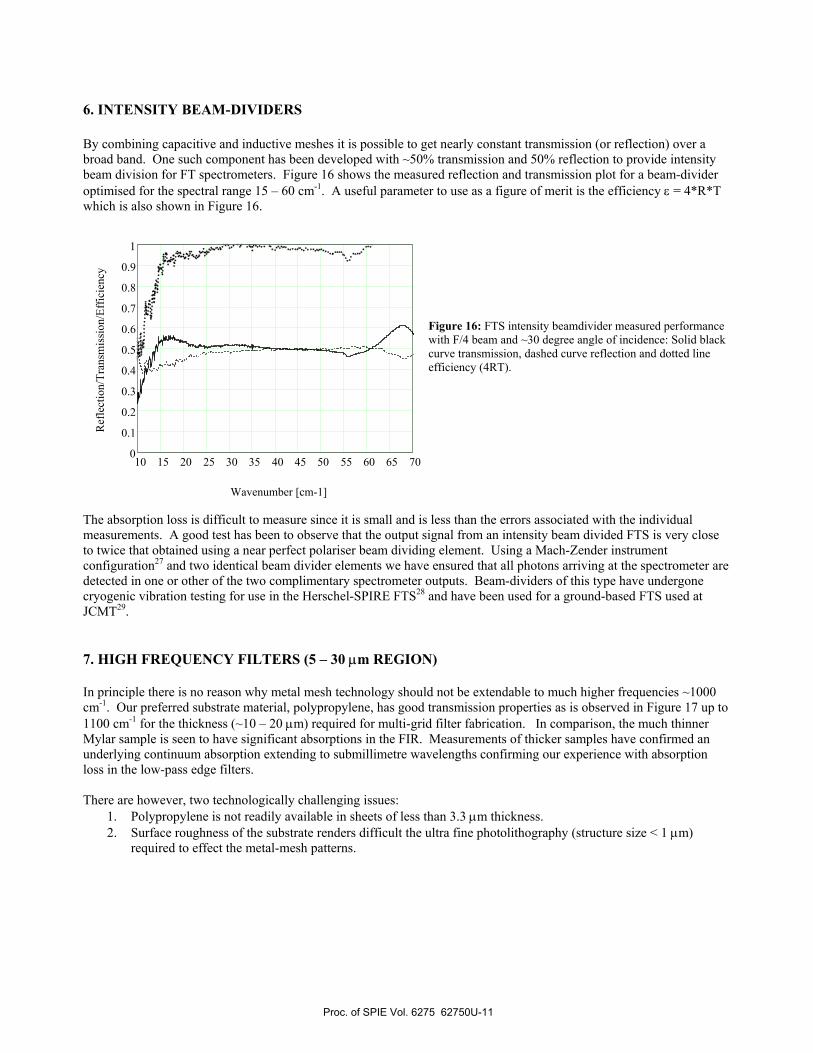
6. INTENSITY BEAM-DIVIDERS By combining capacitive and inductive meshes it is possible to get nearly constant transmission (or reflection) over a broad band. One such component has been developed with ~50% transmission and 50% reflection to provide intensity beam division for FT spectrometers. Figure 16 shows the measured reflection and transmission plot for a beam-divider optimised for the spectral range 15 – 60 cm-1. A useful parameter to use as a figure of merit is the efficiency ε = 4*R*T which is also shown in Figure 16.
Figure 16: FTS intensity beamdivider measured performance with F/4 beam and ~30 degree angle of incidence: Solid black curve transmission, dashed curve reflection and dotted line efficiency (4RT).
The absorption loss is difficult to measure since it is small and is less than the errors associated with the individual measurements. A good test has been to observe that the output signal from an intensity beam divided FTS is very close to twice that obtained using a near perfect polariser beam dividing element. Using a Mach-Zender instrument configuration27 and two identical beam divider elements we have ensured that all photons arriving at the spectrometer are detected in one or other of the two complimentary spectrometer outputs. Beam-dividers of this type have undergone cryogenic vibration testing for use in the Herschel-SPIRE FTS28 and have been used for a ground-based FTS used at JCMT29. 7. HIGH FREQUENCY FILTERS (5 – 30 µm REGION) In principle there is no reason why metal mesh technology should not be extendable to much higher frequencies ~1000 cm-1. Our preferred substrate material, polypropylene, has good transmission properties as is observed in Figure 17 up to 1100 cm-1 for the thickness (~10 – 20 µm) required for multi-grid filter fabrication. In comparison, the much thinner Mylar sample is seen to have significant absorptions in the FIR. Measurements of thicker samples have confirmed an underlying continuum absorption extending to submillimetre wavelengths confirming our experience with absorption loss in the low-pass edge filters. There are however, two technologically challenging issues:
1. Polypropylene is not readily available in sheets of less than 3.3 µm thickness. 2. Surface roughness of the substrate renders difficult the ultra fine photolithography (structure size < 1 µm)
required to effect the metal-mesh patterns.
10 15 20 25 30 35 40 45 50 55 60 65 700
0.1
0.2
0.3
0.4
0.5
0.6
0.7
0.8
0.9
1
Wavenumber [cm-1]
Ref
lect
ion/
Tran
smis
sion
/Eff
icie
ncy
Proc. of SPIE Vol. 6275 62750U-11
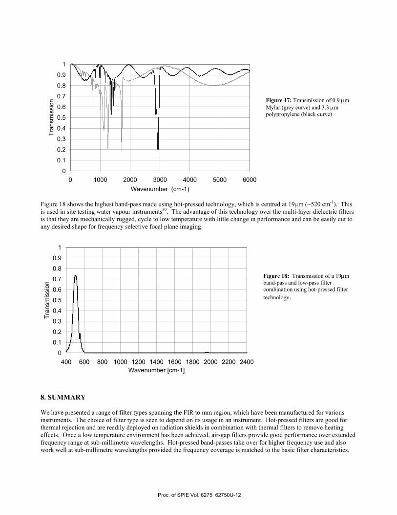
Figure 17: Transmission of 0.9 µm Mylar (grey curve) and 3.3 µm polypropylene (black curve)
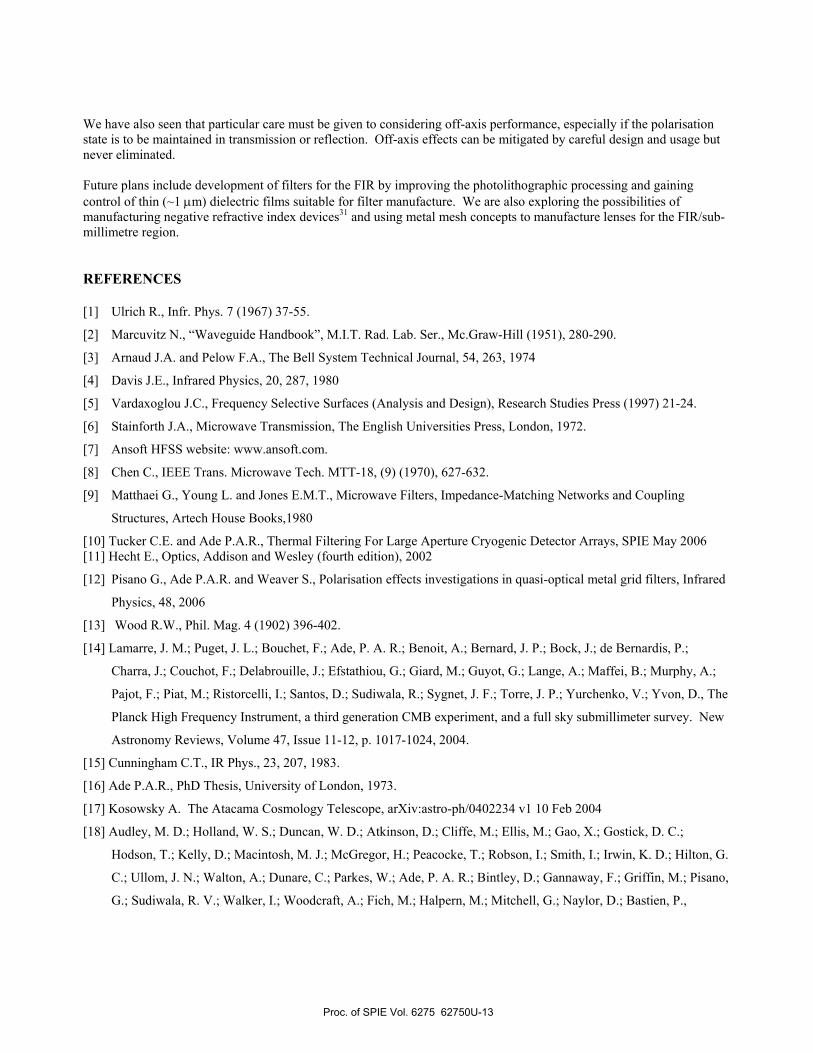
Figure 18 shows the highest band-pass made using hot-pressed technology, which is centred at 19µm (~520 cm-1). This is used in site testing water vapour instruments30. The advantage of this technology over the multi-layer dielectric filters is that they are mechanically rugged, cycle to low temperature with little change in performance and can be easily cut to any desired shape for frequency selective focal plane imaging.
Figure 18: Transmission of a 19µm band-pass and low-pass filter combination using hot-pressed filter technology.
8. SUMMARY We have presented a range of filter types spanning the FIR to mm region, which have been manufactured for various instruments. The choice of filter type is seen to depend on its usage in an instrument. Hot-pressed filters are good for thermal rejection and are readily deployed on radiation shields in combination with thermal filters to remove heating effects. Once a low temperature environment has been achieved, air-gap filters provide good performance over extended frequency range at sub-millimetre wavelengths. Hot-pressed band-passes take over for higher frequency use and also work well at sub-millimetre wavelengths provided the frequency coverage is matched to the basic filter characteristics.
0
0.1
0.2
0.3
0.4
0.5
0.6
0.7
0.8
0.9
1
400 600 800 1000 1200 1400 1600 1800 2000 2200 2400Wavenumber [cm-1]
Tran
smis
sion
0
0.1
0.2
0.3
0.4
0.5
0.6
0.7
0.8
0.9
1
0 1000 2000 3000 4000 5000 6000Wavenumber (cm-1)
Tran
smis
sion
Proc. of SPIE Vol. 6275 62750U-12
We have also seen that particular care must be given to considering off-axis performance, especially if the polarisation state is to be maintained in transmission or reflection. Off-axis effects can be mitigated by careful design and usage but never eliminated. Future plans include development of filters for the FIR by improving the photolithographic processing and gaining control of thin (~1 µm) dielectric films suitable for filter manufacture. We are also exploring the possibilities of manufacturing negative refractive index devices31 and using metal mesh concepts to manufacture lenses for the FIR/sub-millimetre region. REFERENCES
[1] Ulrich R., Infr. Phys. 7 (1967) 37-55.
[2] Marcuvitz N., “Waveguide Handbook”, M.I.T. Rad. Lab. Ser., Mc.Graw-Hill (1951), 280-290.
[3] Arnaud J.A. and Pelow F.A., The Bell System Technical Journal, 54, 263, 1974
[4] Davis J.E., Infrared Physics, 20, 287, 1980
[5] Vardaxoglou J.C., Frequency Selective Surfaces (Analysis and Design), Research Studies Press (1997) 21-24.
[6] Stainforth J.A., Microwave Transmission, The English Universities Press, London, 1972.
[7] Ansoft HFSS website: www.ansoft.com.
[8] Chen C., IEEE Trans. Microwave Tech. MTT-18, (9) (1970), 627-632.
[9] Matthaei G., Young L. and Jones E.M.T., Microwave Filters, Impedance-Matching Networks and Coupling
Structures, Artech House Books,1980
[10] Tucker C.E. and Ade P.A.R., Thermal Filtering For Large Aperture Cryogenic Detector Arrays, SPIE May 2006 [11] Hecht E., Optics, Addison and Wesley (fourth edition), 2002
[12] Pisano G., Ade P.A.R. and Weaver S., Polarisation effects investigations in quasi-optical metal grid filters, Infrared
Physics, 48, 2006
[13] Wood R.W., Phil. Mag. 4 (1902) 396-402.
[14] Lamarre, J. M.; Puget, J. L.; Bouchet, F.; Ade, P. A. R.; Benoit, A.; Bernard, J. P.; Bock, J.; de Bernardis, P.;
Charra, J.; Couchot, F.; Delabrouille, J.; Efstathiou, G.; Giard, M.; Guyot, G.; Lange, A.; Maffei, B.; Murphy, A.;
Pajot, F.; Piat, M.; Ristorcelli, I.; Santos, D.; Sudiwala, R.; Sygnet, J. F.; Torre, J. P.; Yurchenko, V.; Yvon, D., The
Planck High Frequency Instrument, a third generation CMB experiment, and a full sky submillimeter survey. New
Astronomy Reviews, Volume 47, Issue 11-12, p. 1017-1024, 2004.
[15] Cunningham C.T., IR Phys., 23, 207, 1983.
[16] Ade P.A.R., PhD Thesis, University of London, 1973.
[17] Kosowsky A. The Atacama Cosmology Telescope, arXiv:astro-ph/0402234 v1 10 Feb 2004
[18] Audley, M. D.; Holland, W. S.; Duncan, W. D.; Atkinson, D.; Cliffe, M.; Ellis, M.; Gao, X.; Gostick, D. C.;
Hodson, T.; Kelly, D.; Macintosh, M. J.; McGregor, H.; Peacocke, T.; Robson, I.; Smith, I.; Irwin, K. D.; Hilton, G.
C.; Ullom, J. N.; Walton, A.; Dunare, C.; Parkes, W.; Ade, P. A. R.; Bintley, D.; Gannaway, F.; Griffin, M.; Pisano,
G.; Sudiwala, R. V.; Walker, I.; Woodcraft, A.; Fich, M.; Halpern, M.; Mitchell, G.; Naylor, D.; Bastien, P.,
Proc. of SPIE Vol. 6275 62750U-13
SCUBA-2: A large-format TES array for submillimetre astronomy. Nuclear Instruments and Methods in Physics
Research Section A, Volume 520, Issue 1-3, p. 479-482, 2004.
[19] D. Ward-Thompson, P. A. R. Ade, H. Araujo, I. Coulson, J. Cox, G. R. Davis, Rh. Evans, M. J. Griffin, W. K. Gear,
P. Hargrave, P. Hargreaves, D. Hayton, B. J. Kiernan, S. J. Leeks, P. Mauskopf, D. Naylor, N. Potter, S. A.
Rinehart, R. Sudiwala, C. R. Tucker, R. J. Walker, S. L. Watkin, First ground-based 200-um observing with
THUMPER on JCMT - sky characterisation and planet maps. Mon.Not.Roy.Astron.Soc. 364 (2005) 843-848
[20] Paine S., Blundell R., Papa D.C., Barrett J.W. and Radford S.J.E., A Fourier transform spectrometer for
measurement of atmospheric transmission at submillimetre wavelengths. Astron. Soc. Pacific, 112, 767, 108-118,
2000.
[21] Anderson G.P., Clough S.A., Kneizys F.X., Chetwynd J.H. and Shettle E.P.. Tech. Rep. AFGL-TR-86-0110, AFGL
(OPI), Hanscom Air Force Base, Mass., 1987.
[22] Clough S.A., Kneizys F.X. and Davies R.W. Line shape and the water vapour continuum, Atmos. Res., 23, 3-4,
229-241, 1989.
[23] Carlotti M, Ade PAR, Carli B, Chipperfield M, Hamilton PA, Mencaraglia F, Nolt IG, Ridolfi M., Diurnal
variability and night detection of stratospheric hydroxyl radical from far infrared emission measurements. Journal
of Atmospheric & Solar-Terrestrial Physics, vol.63, no.14, Sept. 2001, pp.1509-18. Publisher: Elsevier, UK.
[24] Rieke, George H.; Young, Erick T.; Ade, Peter A.; Beeman, Jeffrey W.; Burmester, William; Cadien, James;
Ennico, Kimberly A.; Gordon, K. D.; Hegge, M.; Heim, Gerald B.; Henderson, M. L.; Horne, T.; Kelly, D. M.;
McMahon, Thomas J.; Neitenbach, M.; Noriega-Crespa, A.; Rivlis, G.; Schnurr, Richard; Schwenker, John P.;
Siewert, S.; Stansberry, J. A.; Strecker, Donald W.; Winters, Gregory S.; Yanoski, C., Performance of the
multiband imaging photometer for SIRTF. Proc. SPIE Vol. 4131, p. 38-49, Infrared Spaceborne Remote Sensing
VIII, Marija Strojnik; Bjorn F. Andresen; Eds, 2000
[25] Griffin M., Abergel A., Ade+ P., André P., Baluteau J-P., Bock J., Franceschini A., Gear W., Glenn J., Griffin D.,
King K., Lellouch E., Naylor D., Olofsson G., Perez-Fournon I., Rowan-Robinson M., Saraceno P., Sawyer E.,
Smith A., SwinyardB., Vigroux L., and Wright G.. Herschel-SPIRE: Design, Performance, and Scientific
Capabilities, SPIE May 2006 (This publication).
[26] Poglisch A., Waelkiens C., Bauer O., Cepa J., Feuchtgruber H., Henning T., van Hoof C., Kerschbaum F., Lemke
D., Renotte E., Rodriguez L.,Saraceno P., Vandenbussche B. The photodetector array camera and spectrometer
(PACS) for the Herschel Space Observatory. SPIE May 2006 (This issue).
[27] Ade, P.A.R., Hamilton, P., Naylor, D.A., Fourier Transform Spectroscopy: New Methods and Applications, An
Absolute Dual Beam Emission Spectrometer. OSA, 90, 1999.
[28] Swinyard, Bruce M.; Dohlen, Kjetil; Ferand, Didier; Baluteau, Jean-Paul; Pouliquen, Dominque; Dargent, Pascal;
Michel, Guy; Martignac, Jerome; Ade, Peter A. R.; Hargrave, Peter C.; Griffin, Matthew J.; Jennings, Donald E.;
Caldwell, Martin E., Imaging FTS for Herschel SPIRE. SPIE, Volume 4850, pp. 698-709, 2003.
Proc. of SPIE Vol. 6275 62750U-14

[29] Naylor, D.A., Gom, B.G., Schofield, I.S., Tompkins, G.J., Davis, G.R., Mach-Zehnder Fourier transform
spectrometer for astronomical spectrocopy at submillimeter wavelengths. SPIE, Millimeter and Submillimeter
Detectors for Astronomy 4855, 540-551, 2003.
[30] Naylor D.A., Chapman I.M. and Gom B.G., Measurements of atmospheric water vapor above Mauna Kea using an
infrared radiometer. SPIE Vol. 4815, 2002.
[31] Pendry J.B., Negative refraction makes a perfect lens, Phys. Rev. Letters, 85, 3966-3969, 2000
Proc. of SPIE Vol. 6275 62750U-15