Embed Size (px)
Citation preview

Reference
r, 1NBS ^
, Publii^-4: cations
liniilmi’llM/i'STAND & TECH R.I.C.
AlllOS flTieOE 31-2214
A Review of Measurements,Calculations and Specifications ofAir Leakage Through Interior DoorAssemblies
Daniel Gross
Center for Fire Research
National Engineering Laboratory
U.S. Department of CommerceNational Bureau of Standards
Washington, DC 20234
February 1981
-QC
100
.056
81-221^1
19ol
S. DEPARTMENT OF COMMERCE
mONAL BUREAU OF STANDARDS
V


National Bureau ot Standards
Ubtarv.,E-OlB"*®-
APR 1 ’8®'
Hoi Ck cf - /: <
'U^CfNBSIR 81-2214 m.
A REVIEW OF MEASUREMENTS,CALCULATIONS AND SPECIFICATIONS OFAIR LEAKAGE THROUGH INTERIOR DOORASSEMBLIES
Daniel Gross
Center for Fire Research
National Engineering Laboratory
U.S. Department of CommerceNational Bureau of Standards
Washington, DC 20234
February 1981
U.S. DEPARTMENT OF COMMERCE, Malcolm Baldrige, Secretary
NATIONAL BUREAU OF STANDARDS, Ernest Ambler. Director

"cj<|^
^
#;:>1
F3J5P' •
':.-f''^ 'I't
*fc-
:mih.#"•.aTW3|^3«U^AJM ’(O w^rvifi A
|IOUG«'»-ii^3pAJ^^ A,.W'
'
'u;,’
r.
b^u f]
:*
«
I*'
'
I
fc.>, .
'^t
r%.'
;*W
,
'S (#tr»ft<3
^''
hi
, Af'
'M >9n ^t'JS.j
¥T*^*«pi«|4
.atl'vV
' HKi .rtC)iig[T»M®«rW'
i«-
A- 'f.
'
A ; .»!
% r A -f I#•i
'
Sf,M w ’-«N
4^ ,.', f‘i
rimi'.i
"A'
'
.. viK'^3to:
^
K V.» .
k
'miffi mi
-
/’•• 'Vj
\'S| 'i’iv.
^9:
-l-jli
'H'

TABLE OF CONTENTS
Page
LIST OF TABLES iv
LIST OF FIGURES Iv
Abstract 1
1. INTRODUCTION 1
2. GENERAL PRINCIPLES 3
3. TEST METHODS 6
4. SPECIFICATIONS 8
5. MEASUREMENTS 9
6. DISCUSSION 11
7. CONCLUSIONS 12
8. REFERENCES 14
ill

LIST OF TABLES
Page
Table 1. Values of exponent in equation 1 17
Table 2. Measured and estimated air leakage rates for doors . . 18
Table 3. Measured and estimated air leakage rates for buildingcomponents 19
LIST OF FIGURES
Page
Figure 1. Discharge coefficients for orifice flow 20
iv

A Review of Measurements, Calculations and Specifications
of Air Leakage Through Interior Door Assemblies
Daniel Gross
ABSTRACT
A review was made of measurements and calculations
of air leakage through door assemblies in order to
evaluate their effectiveness as barriers to smoke
flow. It was noted that typical "fire doors" are
not capable of meeting proposed limitations of air
leakage at ambient temperatures. It was also noted
that significant air leakage may occur through
interior walls which contain fire doors. It was
concluded that first priority should be given to
developing and validating a standardized test
method for the accurate and consistent measure-
ment of air leakage through door assemblies.
Key Words: Air leakage, building, door, fire door,
fire test, infiltration, smoke control, smoke
movement
.
1. INTRODUCTION
For fire safety purposes, smoke is defined as the airborne solid
and liquid particulates and gases evolved when a material undergoes
pyrolysis or combustion. It is obvious that an open door will readily
permit smoke to pass from its source in a building fire to other areas
in the building. It is also generally accepted that a closed door will
limit the passage of smoke, and, in controlled occupancies such as
hospitals, schools, and certain office and apartment buildings, doors
1

are required to be self-closing or to close automatically upon operation
of an installed smoke detector device. However, the effectiveness of a
door as a barrier to smoke is not well established, and it is the intent
of this report to provide a review of the current status of our knowledge
of air (and smoke) flow measurements through door assemblies in terms of
occupant protection in the event of fire.
From the standpoint of fire, there are several different types of
doors, each of which serves a specified purpose in current building
codes^. A fire door is mandated as part of the building fire containment
system primarily for property protection purposes. When installed in a
fire separation wall of three or four hour rating, a fire door having a
three hour rating is generally required. There is no expressed require-
ment for the prevention of smoke passage by a door in a fire separation
wall. An exit stair door is expected to provide ready access to the
stairshaft for fleeing occupants while maintaining its integrity and
preventing passage of flames or heat for an extended period of exposure
to a fire located in the corridor. In the usual case, where the stair
enclosure walls are required to have a two hour fire resistance rating,
the exit stair door assembly is required to have a 1-1/2 hour fire
resistance rating. However, there is no mention of the ability of the
door assembly to prevent the passage of smoke. A horizontal exit door
is expected to provide a barrier to horizontal fire spread while per-
mitting building occupants to pass through the horizontal exit to (a)
seek refuge on the unexposed side of the exit, or (b) continue on to an
exit leading directly to the outside. The exit door is also required to
have a 1-1/2 hour fire resistance rating and also to serve as a "smoke
barrier". However, there is no prescribed test method or meaningful
performance criteria on which to assess the door’s effectiveness as a
smoke barrier. A corridor/room separation door is expected to have a
dual function; (a) to keep a fire located in the corridor from entering
a room (patient room, school room, apartment, etc,), and (b) to keep a
^ In common practice, fire doors are classified by a letter designationaccording to the opening for which the door is suitable and an hourlyrating designation [1]; the type description according to use isconsidered more appropriate here.
2
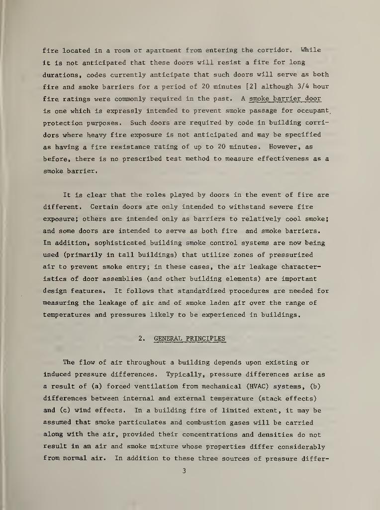
fire located in a room or apartment from entering the corridor. While
it is not anticipated that these doors will resist a fire for long
durations, codes currently anticipate that such doors will serve as both
fire and smoke barriers for a period of 20 minutes [2] although 3/4 hour
fire ratings were commonly required in the past. A smoke barrier door
is one which is expressly intended to prevent smoke passage for occupant,
protection purposes. Such doors are required by code in building corri-
dors where heavy fire exposure is not anticipated and may be specified
as having a fire resistance rating of up to 20 minutes. However, as
before, there is no prescribed test method to measure effectiveness as a
smoke barrier.
It is clear that the roles played by doors in the event of fire are
different. Certain doors are only intended to withstand severe fire
exposure; others are intended only as barriers to relatively cool smoke;
and some doors are intended to serve as both fire and smoke barriers.
In addition, sophisticated building smoke control systems are now being
used (primarily in tall buildings) that utilize zones of pressurized
air to prevent smoke entry; in these cases, the air leakage character-
istics of door assemblies (and other building elements) are important
design features. It follows that standardized procedures are needed for
measuring the leakage of air and of smoke laden air over the range of
temperatures and pressures likely to be experienced in buildings.
2. GENERAL PRINCIPLES
The flow of air throughout a building depends upon existing or
induced pressure differences. Typically, pressure differences arise as
a result of (a) forced ventilation from mechanical (HVAC) systems, (b)
differences between Internal and external temperature (stack effects)
and (c) wind effects. In a building fire of limited extent, it may be
assumed that smoke particulates and combustion gases will be carried
along with the air, provided their concentrations and densities do not
result in an air and smoke mixture whose properties differ considerably
from normal air. In addition to these three sources of pressure differ-
3

ence, there is also a pressure effect due to the expansion of hot gases
in the vicinity of the fire. In a large building, this effect will be
fairly localized.
The flow of air through a corridor, through an open doorway, or
through small cracks in walls or small gaps around closed doors follows
the same general relationship. Thus, the flow of air at constant
temperature through an opening (or passageway) is expressed in terms of
the area of the opening and the static pressure differential across the
opening as follows:
Q = KA(Ap)^ [1]
where Q = volume flow rate of air
K = a flow factor incorporating the discharge coefficient (C,)d
of the leakage openings, and the relationship between the
units used
A = area of the opening or passage
Ap = pressure difference
n = exponent which can vary between 0,5 and 1,0
3 2When Q is expressed in m /s, A in m , and Ap in Pa, K = 0,827
In considering flow through cracks around closed door assemblies,
it has been common to assume that n = 0.5 and C, = 0.6 to 0.7, which area
typical values for flow through thin-walled, square-edged (or sharp-edged)
orifice plates or other small openings. Then, A represents the "equiva-
lent area of opening".
The exponent n should not automatically be assumed equal to 0.5.
At fairly high Reynolds numbers, corresponding to sizable characteristic
dimensions and velocities where the flow is turbulent and the flow
resistance is due mainly to inertia forces, n approaches 0.5. However,
in laminar flow, where the resistance is mainly due to viscous forces
and the Reynolds number is low, n approaches 1. Table 1 lists examples
of assumed or derived values of n.
4
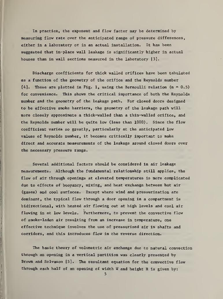
In practice, the exponent and flow factor may be determined by
measuring flow rate over the anticipated range of pressure differences,
either in a laboratory or in an actual installation. It has been
suggested that in-place wall leakage is significantly higher in actual
houses than in wall sections measured in the laboratory [3].
Discharge coefficients for thick walled orifices have been tabulated
as a function of the geometry of the orifice and the Reynolds number
[4]. These are plotted in Fig. 1, using the Bernoulli relation (n = 0.5)
for convenience. This shows the critical importance of both the Reynolds
number and the geometry of the leakage path. For closed doors designed
to be effective smoke barriers, the geometry of the leakage path will
more closely approximate a thick-walled than a thin-walled orifice, and
the Reynolds number will be quite low (less than 1000) . Since the flow
coefficient varies so greatly, particularly at the anticipated low
values of Reynolds number, it becomes critically Important to make
direct and accurate measurements of the leakage around closed doors over
the necessary pressure range.
Several additional factors should be considered in air leakage
measurements. Although the ftmdamental relationship still applies, the
flow of air through openings at elevated temperatures is more complicated
due to effects of buoyancy, mixing, and heat exchange between hot air
(gases) and cool surfaces. Except where wind and pressurization are
dominant, the typical flow through a door opening in a compartment is
bidirectional, with heated air flowing out at high levels and cool air
flowing in at low levels. Furthermore, to prevent the convective flow
of smoke-laden air resulting from an increase in temperature, one
effective technique involves the use of pressurized air in shafts and
corridors, and this introduces flow in the reverse direction.
The basic theory of volumetric air exchange due to natural convection
through an opening in a vertical partition was clearly presented by
Brown and Solvason [5]. The resultant equation for the convective flow
through each half of an opening of width W and height H is given by:
5

1/2
[ 2 ]Q =C,WHd
3/2
]
where g = gravitational constant
p = (avg) fluid density
Ap = difference in fluid densities
This was extended by Shaw to take into account the combined effect
of natural convection and forced air flow; subsequently Shaw and Whyte
calculated the forced air supply required to counter the effects of
small temperature differences (0 to 12 K) so as to prevent the exchange
of contaminated air through open or partially open doors in hospitals [6],
The following equation represents the leakage flow of air through an
opening against the forced air supply of velocity V^:
Q3 gAp ^ - x-*
[3]
It may also be used to determine the value of which will reduce Q
to zero.
For the specific application involving a closed door, measurements
are needed of the minimum flows of cool air and the corresponding
pressure differences., to prevent any air from flowing from the heated
area through the door assembly. There are no known measurements of this
kind.
3. TEST METHODS
Standard test methods for measuring air leakage through exterior
building elements have been used for at least 15 years. The current
ASTM method for determining the air infiltration resistance of exterior
windows, doors and walls [7] was originally published in 1965. The
ASTM E 283 test method consists of sealing the test specimen into or
against one face of an air chamber and supplying air to (or exhausting
air from) the chamber at the rate required to maintain the specified
6

test pressure difference across the specimen. Since this test is used
for exterior building elements, air leakage measurements are commonly2
made at a pressure difference of 75 Pa (1.57 Ibf/ft ) corresponding to a
wind velocity of 11.1 m/s (25 mph), although other pressure difference
levels are possible.
A similar test method was adopted in 1968 as a British Standard [8]
in which the pressure is applied in 50 Pa steps up to a maximum of 1000
Pa. In the test method adopted in 1975 as a European Standard [9] and in
the version being balloted as an ISO standard by ISO Committee TC 162 on
Windows [10], the pressure is also applied in stages (50, 100, 150, 200,
300, 400, 500, 600 Pa) up to the maximum pressure required for the test.
From the standpoint of pressure differences likely to exist under
fire conditions, including winter stack effect in tall buildings and smoke
control pressurization techniques, interior building pressures as high as
100 Pa are unlikely. ISO Committee TC 92 on Fire Tests is currently
considering three separate test methods for measuring air flow through
interior door assemblies. The test method proposed for use at ambient
indoor temperature (25 °C) also measures air flow across a door assembly
at several pressure difference levels (5, 10, 20, 30, 50, 70 and 100 Pa)
[11]. It is intended that other test methods would be developed for
measuring air leakage at elevated temperatures, (e.g., at temperatures
which correspond to the standard fire exposure for fire doors [12]) and
at moderate temperatures (e.g., 300-500 °C)
.
None of these methods
actually addresses the more direct but difficult question of measuring
the quantity of smoke particulates which flow past the door assembly,
the apparent assumption being that (a) the particulates will not be
filtered or deposited out in passing through the door gaps or (b) the
flow of smoke-laden air is essentially equivalent to the flow of air
mixed with CO and other "smoke" gases.
In the usual case, these test methods do not prescribe the apparatus
in detail, providing only the measurement principle and a stated measure-
ment accuracy. Thus the apparatus may be small, large, or adjustable in
7

size and temporary or permanent. There are approximately 20 laboratories
in the U.S. equipped to perform the ASTM E 283 test, although it is
likely that there are wide variations in the size of the test chamber,
the method of sealing, the type of flow and pressure measuring devices,
etc. No data on interlaboratory testing are known or provided. The2
situation is similar for the proposed international test methods .
4. SPECIFICATIONS
Air leakage rates are sometimes specified for selected types of
exterior doors to limit energy losses due to air infiltration. Although
the air leakage rate may be specified in terms of the door area, it
seems more reasonable to express it in terms of the crack length
(perimeter) through which the leakage occurs. For example, one standard2 3
[13] sets a limit of 1,25 cfm/ft (equivalent to 7.62 m /h*m of crack
length for a 1 by 2 m door) at a pressure difference of 0.3 in wg (75
Pa) for a residential-type swinging door. For a similar application, a
specification for insulated steel door systems [14] specifies a value
approximately 40 percent of this limit, whereas another specification
[15] permits a leakage rate four times as large, i.e., equivalent to
30,5 m^/h*m.
Whereas exterior doors are specifically designed with weather-
stripping and seals to limit air leakage, interior doors are not so
designed except for special applications. In the U.S., there are no
known specifications limiting air leakage through interior door assemblies
for smoke control purposes. The Uniform Building Code Standard No. 43-2
(1979 edition) defines a smoke and draft control door assembly in terms
of performance in the standard fire endurance test for an exposure period
of not less than 20 minutes. The acceptance conditions are based on
limitations on (1) flaming on the unexposed surface, (2) excessive move-
ments, and (3) emission of excessive smoke from the door. In addition.
One known commercial source for an apparatus for measuring air leakageof doors and windows is: ALCO - Fensterpriifstand Typ 3030 SP, manu-factured by ALCO Bauzubehorgesellschaf t MBH & Co.
,
Goslar, W. Germany.8

it is required that "smoke and draft control door assemblies shall be
provided with a gasket so installed as to provide a seal where the door
meets the stop on both sides and across the top. The gasketing need not
be installed on the test assembly". It is clear that the effectiveness
of sealing methods are not quantitatively prescribed. In 1977, the NFPA
Committee on Fire Doors and Windows prepared a Recommended Practice for
the Installation of Smoke and Draft Control Door Assemblies (NFPA No. 105-
1977) . This proposal was Intended to assist public safety authorities
in considering methods for restricting and minimizing the potential flow
of smoke and gases through door opening assemblies. It contained
recommendations on frames, doors, hanging means, closing, holding and
releasing means, detection, latching and sealing. As part of the recom-
mendation for sealing, gasketing was to be provided along the door
perimeter, and clearances (e.g., for carpeting) were to be "kept to a
minimum". While this Recommended Practice was never adopted, it seems
obvious that a quantitative performance level based on a suitable
standard test method would have made such a Recommended Practice and
other general requirements more meaningful and practical.
It may be of interest to note that in Germany the following tenta-
tive requirements have been proposed to limit the flow of heated (200°C)
3air through Interior door assemblies: (1) 60 m /h at Ap = 10 Pa for the
Ocomplete door assembly as used, (2) 20 m /h at Ap = 10 Pa for the door
assembly with the threshold taped. The second measurement using an
impervious seal at the bottom ledge of the door takes into account the
fact that doors are usually undercut and that leakage at the threshold
(floor) level would be disproportionately high in the (uniform pressure)
laboratory test compared to the actual situation in a building.
5 . MEASUREMENTS
A summary of some published information on air leakage rates for
doors is given in Table 2, Data for windows, walls, and complete
buildings are given in Table 3.
9
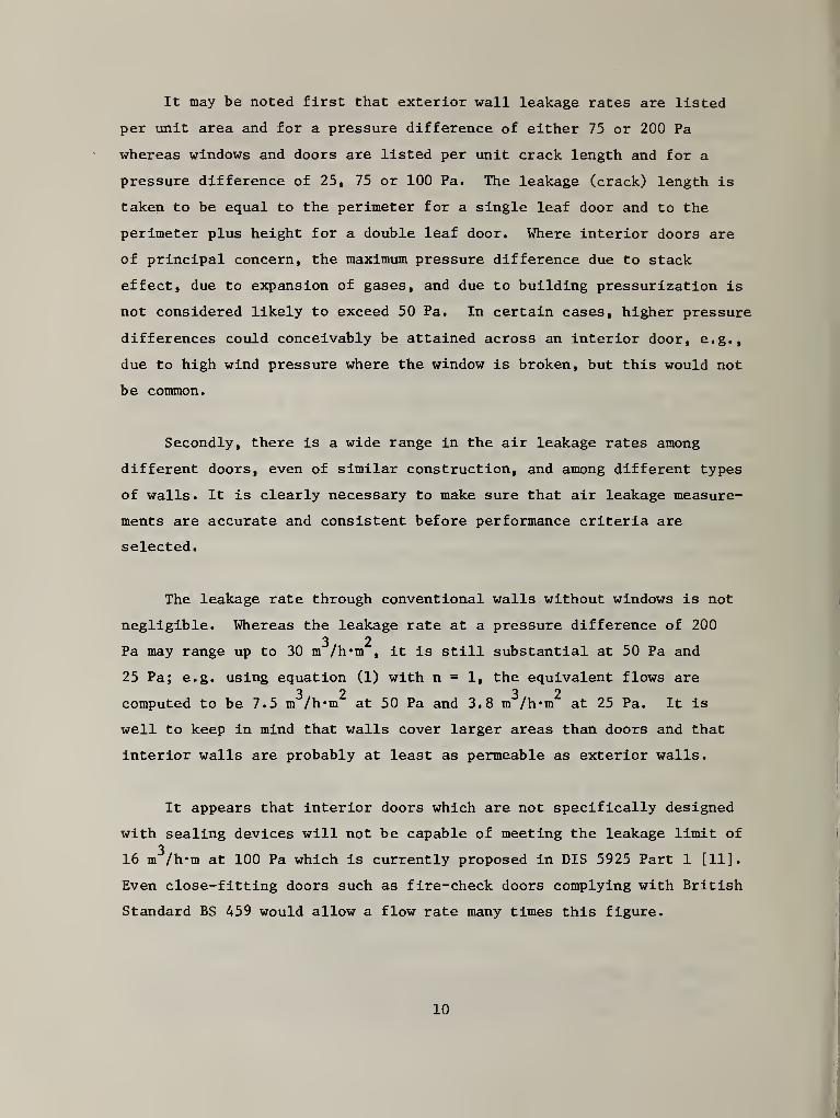
It may be noted first that exterior wall leakage rates are listed
per unit area and for a pressure difference of either 75 or 200 Pa
whereas windows and doors are listed per unit crack length and for a
pressure difference of 25, 75 or 100 Pa. The leakage (crack) length is
taken to be equal to the perimeter for a single leaf door and to the
perimeter plus height for a double leaf door. Where interior doors are
of principal concern, the maximum pressure difference due to stack
effect, due to expansion of gases, and due to building pressurization is
not considered likely to exceed 50 Pa. In certain cases, higher pressure
differences could conceivably be attained across an interior door, e.g.,
due to high wind pressure where the window is broken, but this would not
be common.
Secondly, there is a wide range in the air leakage rates among
different doors, even of similar construction, and among different types
of walls. It is clearly necessary to make sure that air leakage measure-
ments are accurate and consistent before performance criteria are
selected.
The leakage rate through conventional walls without windows is not
negligible. Whereas the leakage rate at a pressure difference of 200
3 2Pa may range up to 30 m /h*m
, it is still substantial at 50 Pa and
25 Pa; e.g. using equation (1) with n = 1, the equivalent flows are3 2 3 2
computed to be 7.5 m /h*m at 50 Pa and 3,8 m /h*m at 25 Pa. It is
well to keep in mind that walls cover larger areas than doors and that
interior walls are probably at least as permeable as exterior walls.
It appears that interior doors which are not specifically designed
with sealing devices will not be capable of meeting the leakage limit of3
16 m /h*m at 100 Pa which is currently proposed in DIS 5925 Part 1 [11],
Even close-fitting doors such as fire-check doors complying with British
Standard BS 459 would allow a flow rate many times this figure.
10

Finally, as an Illustrative example, the estimated leakage through
a 1 by 2 m "smoke control door assembly" designed to the suggested limit3
in DIS 5925 Part 1 would be 70 m /h at 50 Pa. At this pressure, the
leakage through the walls of an interior (or "core") stair shaft
measuring 3 by 6 m and constructed of concrete block may be about 120
3m /h per story. Thus, the advantage of using an effective smoke control
door assembly may be limited if the door is mounted in a wall of normal
construction.
6. DISCUSSION
This report was prepared to provide a review of available measure-
ments of air leakage through Interior door assemblies and a discussion
of future needs and approaches for defining the performance of "smoke
control doors". It has been pointed out that currently used doors
separating each room from the corridor (e.g. , apartment entrance doors),
smoke barrier doors used in corridors, and exit stair doors will not3
meet the arbitrary 16 m /h*m leakage limit proposed in DIS 5925 Part 1.
Is there a more rational basis for this limit or other limit?
In 1970, McGuire et al [16] suggested that the control of smoke
within a high building could, as a first approximation, be accomplished
by limiting the density of smoke at any point to 1 percent of the smoke
density at the source. This value was based on a review of data on
smoke generation, and on visibility in smoke-filled rooms and occupant
tenability. The concept of using a limiting value of 1 percent may also
be extended to air flow through door openings. What would such an
approach provide in terms of evaluating the performance of conventional
apartment entrance doors and typical fire-rated stair shaft doors?
For example, what is the likely flow of air past a closed apartment
entrance door if the air flow were limited to 1 percent of the flow
through the open door? Assuming a temperature difference of 10 K, the
convective air flow through an open apartment entrance door according to3 3Equation 2 would be approximately 0.48 m /s (1730 m /h) . Thus, 1 percent
11
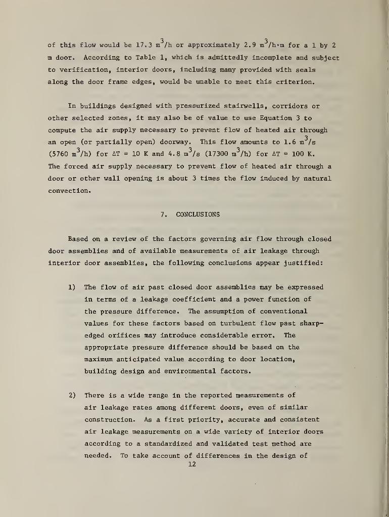
3 3of this flow would be 17,3 m /h or approximately 2.9 m /h*m for a 1 by 2
m door. According to Table 1, which is admittedly incomplete and subject
to verification, interior doors, including many provided with seals
along the door frame edges, would be unable to meet this criterion.
In buildings designed with pressurized stairwells, corridors or
other selected zones, it may also be of value to use Equation 3 to
compute the air supply necessary to prevent flow of heated air through3
an open (or partially open) doorway. This flow amounts to 1.6 m /s
(5760 m^/h) for AT = 10 K and 4.8 m^/s (17300 m^/h) for AT = 100 K.
The forced air supply necessary to prevent flow of heated air through a
door or other wall opening is about 3 times the flow induced by natural
convection.
7. CONCLUSIONS
Based on a review of the factors governing air flow through closed
door assemblies and of available measurements of air leakage through
interior door assemblies, the following conclusions appear justified:
1) The flow of air past closed door assemblies may be expressed
in terms of a leakage coefficient and a power function of
the pressure difference. The assumption of conventional
values for these factors based on turbulent flow past sharp-
edged orifices may introduce considerable error. The
appropriate pressure difference should be based on the
maximum anticipated value according to door location,
building design and environmental factors.
2) There is a wide range in the reported measurements of
air leakage rates among different doors, even of similar
construction. As a first priority, accurate and consistent
air leakage measurements on a wide variety of interior doors
according to a standardized and validated test method are
needed. To take account of differences in the design of
I

doors, door frames, and sealing devices, as well as the
effects of the anticipated differences of pressure, many
interior door assemblies will need to be tested with air
pressure applied separately in each direction.
3) Interior doors which are not specifically designed with
special sealing devices will not be capable of meeting3
the leakage limit of 16 m /h*m at 100 Pa which is
currently proposed in DIS 5925 Part 1. Even many doors
provided with seals along the door frame edges may be
unable to meet a criterion based on limiting flow to 1
percent of the open door flow.
4) An appreciable fraction of air leakage may occur through
Interior walls, including stair shaft walls, according to
published measurements of leakage rates. Thus, the
advantage of using an effective smoke control door assembly
may be limited if the door is mounted in a wall of normal
construction.

REFERENCES
1. NFPA 80-1979, Standard for Fire Doors and Windows, Appendix F
Classification, 1979.
2. Degenkolb, J.G. , "Fire Door Assemblies - What Do the Ratings Mean?",Building Official and Code Administrator, pp. 61-64, July/Aug 1975.
3. ASHRAE Book of Fundamentals, Chapter 21, 1977.
4. Idel'chlk, I.E. , "Handbook of Hydraulic Resistance", Moscow, 1960.
5. Brown, W.G. and Solvason, K.R., "Natural Convection ThroughRectangular Openings in Partitions", Inti. J. of Heat and MassTransfer, _5, p. 859-868, Sept. 1962.
6. Shaw, B.H. and Whyte, W. , "Air Movement Through Doorways - TheInfluence of Temperature and Its Control by Forced Airflow", Bldg.Service Engineer, 42 , pp. 210-218, Dec. 1974.
7. ASTM E 283-73, "Standard Test Method for Rate of Air LeakageThrough Exterior Windows, Curtain Walls, and Doors", Part 18,Annual Book of ASTM Standards, 1980.
8. British Standards Institution BS 4315:Part 1, "Methods of Testfor Resistance to Air and Water Penetration", 1968,
9. European Standard EN 42:Part 1 (also BS 5368:Part 1:1976), "Methodsof Testing Windows:Part 1. Air Permeability Test", Oct. 1975.
10. ISO Draft International Standard DIS 6613, "Windows and WindowDoors - Air Permeability Test".
11. ISO Draft International Standard DIS 5925/1, "Fire Tests -
Evaluation of Performance of Smoke Control Door Assemblies -
Part 1: Ambient Temperature Test", Feb. 1980.
12a. ISO 3008, "Fire Resistance Tests - Door and Shutter Assemblies",April 1976.
b. ASTM E 152-80, "Fire Tests of Door Assemblies", Part 18, AnnualBook of ASTM Standards, 1980.
13. ASHRAE 90-75, Energy Conservation in New Building Design, TheAmerican Society of Heating, Refrigerating and Air-ConditioningEngineers, Inc., New York, 1975.
14. ISDSI-109, Door Insulating System Index (DISI) for Insulated SteelDoor Systems, Insulated Steel Door Systems Institute, Cleveland,OH., 1979.
14

15. ANSI/AAMA 1102,7-1977 Voluntary Master Specification for AluminumStorm Doors, Architectural Aluminum Manufacturers Assn., Chicago,IL., 1977.
16. McGuire, J.H., Tamura, G.T. , and Wilson, A.G., "Factors in
Controlling Smoke in High Buildings", ASHRAE Symp. Proc. , "FireHazards in Buildings", Jan. 19-22, 1970.
17. Hobson, P.J. and Stewart, L.J., "Pressurization of Escape Routesin Buildings", FR Note 958, British Joint Fire Research Organiza-tion, Dec. 1972.
18a. Houghten, F.C. and Ingels, M,, "Infiltration Through Plastered and
Unplastered Brick Walls", ASHVE Trans. 33 , p. 377, 1927.
b. Larson, G.L. , Nelson, D.W. and Bratz, C. , "Air InfiltrationThrough Various Types of Brick Wall Construction", ASHVE Trans.
16, p. 99, 1930.
19. Tamura, G.T. , "Computer Analysis of Smoke Control with BuildingAir Handling Systems", ASHRAE Journal, p. 46-54, Aug. 1972.
20. Butcher, G.C. and Parnell, A.C., "Smoke Control in Fire SafetyDesign", E. and F.N. Spon, Ltd. publishers, 1979.
21. Tamura, G.T. and Shaw, C.Y., "Air Leakage Data for the Designof Elevator and Stair Shaft Pressurization Systems", ASRAE Trans.
81, 1975.
22. Poulsen, P.E. , "Smoke Control Doors Test Report", Danish NationalInstitute for Testing of Materials, 1979, (ISO/TC 92/WG 3 N 218).
23. Report of ASTM E 283 tests conducted by commercial laboratoryfor sponsor, 1973.
24. Tests reported by Hans Strom, Jl-Te AB for Mr. Jackman(TRADA), June 1979 (ISO/TC 92/WG 3 N 236).
25. Tests reported by Timber Research and Development Association,June 1979 (ISO/TC 92/WG 3 N 236).
26. Air Leakage Test Chamber for Smoke Control Doors (SMP,
Dortmund) 1979 (ISO/TC 92/WG 3 N 228).
27. Thorogood, R.P. , "Resistance to Air Flow Through External Walls",BRE Information Paper 14/79, 1979.
28. Tamura, G.T.
,
"Measurement of Air Leakage Characteristics of HouseEnclosures", ASHRAE Trans. 81 , 1975.
15

29. Carruthers, J.F.S. and Newman, C.J., "The Repeatability andReproducibility of Test Results on Windows and Wall Span Elementsand the Expected Results", BRE Current Paper, CP 49/77, 1977.
30. Data from Figs. 4.39, 4,40 and Fig 4.41 of Japanese report.
31. Data from Building Research Station (1971) and PrincessRisborough Laboratory (1972), referenced in [14].
16
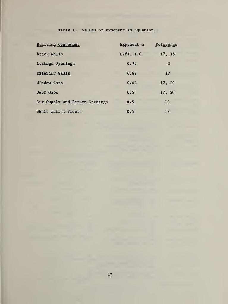
Table 1. Values of exponent in Equation 1
Building Component Exponent n Reference
Brick Walls 0.87, 1.0 17, 18
Leakage Openings 0.77 3
Exterior Walls 0.67 19
Window Gaps 0.62 17, 20
Door Gaps 0.5 17, 20
Air Supply and Return Openings 0.5 19
Shaft Walls; Floors 0.5 19
17
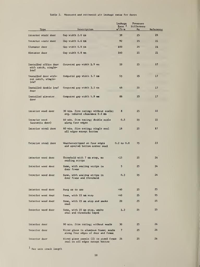
Table 2. Measured and estimated air leakage rates for doors
Type Description
LeakageRate ^
m^/h'm
PressureDifference
Pa
Interior stair door Gap width 2. 0 mm 38 25
Interior stair door Gap width 4 • 6 mm 92 25
Elevator door Gap width 4« 8 mm 100 25
Elevator door Gap width 6.8 mm 140 25
Installed office doorwith catch, single-leaf
Computed gap width 1.9 mm 29 25
Installed door with-out catch, single-leaf
Computed gap width 3.7 mm 55 25
Installed double leaf
door
Computed gap width 3.2 mm 48 25
Installed elevatordoor
Computed gap width 5 . 9 mm 88 25
Interior wood door 30 min. fire rating; withoutavg. rebated clearance 0.6
seals;Tnm
8 25
Interior wood 60 min. fire rating; double seals 0.5 25
(acoustic door) along four edges
Interior steel door 60 min. fire rating; single seal 16 25
all edges except bottom
Exterior steel door Weatherstrlpped on four edgesand special bottom comer seal
0.2 to 0.8 75
Interior wood door Threshold with 7 mm stop, nosealing strips
>15 25
Interior wood door Same, with sealing strips In
door frame5 25
Interior wood door Same, with sealing strips Indoor frame and threshold
0.3 25
Interior wood door Hung as In use >40 25
Interior wood door Same, with 25 mm stop >40 25
Interior wood door Same, with 25 mm stop and smokeseal
20 25
Interior wood door Same, with 25 mm stop, smokeseal and threshold taped
1.3 25
Interior door 90 min. fire rating; without seals 30 25
Interior door Wired glass In aluminum frame; sealsalong four edges of door and frame
7 25
Interior door Wired glass panels (2) In steel frameseal on all edges except bottom
24 25
Per unit crack length
Reference
21
21
21
21
17
17
17
17
22
22
17
23
24
24
24
25
25
25
25
26
26
26
18

Table 3. Measured and estimated air leakage rates for building components
Component DescriptionLeakage Rate
11 ^ /h m^ m^/h mPressure
Difference Reference
Buildings
School Precast concrete panel walls;gasket Joints; plasterboardlining.
5 200 27
House Timber-frame panels; flberboardsheathing; plasterboard lining.
10 200 27
Walls
Factory(windowless)
Profiled steel cladding;quilt Insulation; plasterboardlining.
30 200 27
Warehouse(windowless)
As above. 20 200 27
ElevatorShaft
Cast-ln-place concrete 4-15 75 21
ElevatorShaft
Concrete block or clay tile block. 30-35 75 21
Stair Shaft Cast-ln-place concrete; concreteor tile block.
0.5-4 75 21
Wood Frame Insulated 1 and 2 story 3-23 75 28
Wood Frame Shingles; sheathing; bldg, paper;lath and plaster (3 coats)
0.1 75 3
Brick 8.5 In. thick, unplastered. 7 75 3
Brick 8.5 In. thick, plastered 0.06 75 3
Windows
Household Weatherstrlpped 2.2-13.8 100 29
Non Weatherstrlpped 6-25 100 29
Fixed 0.006-0.08 75 30
Wooden Sash 5-25 75 30
Metallic Sash 0.5-30 75 30
Household, Nonweatherstrlpped, avg. fitwood double-hung
5 75 3
Household, Weatherstripped, avg. fitwood double-hung
3 75 3
Pivoted 5.8 (1-20) 25 31
Pivoted and weatherstrlpped 0.8 (0.1-6) 25 31
Sliding 2.2 (0.5-9) 25 31
Per unit area; per unit crack length
19

Figure
1.
Discharge
coefficients
for
orifice
flow
PQ 1N3I3IJJ303 39)IVH3Sia
20
REYNOLDS
NUMBER
N
NBS>114A (REV. 9-78)
2.C0^t Accession No,U.S. DEPT. OF COMM.
BIBLIOGRAPHIC DATASHEET
1. PUBLICATION OR REPORT NO.
NBSIR 81-2214
Reciptenf$ Accessloii No»
4. TITLE AND SUBTITLE
A Review of Measurements, Calculations and Specificationsof Air Leakage Through Interior Door Assemblies
5. Publication Date
February 1981S. Pedorming Organization Code
7. AUTHOR(S)
Daniel Gross
8. Performing Organ. Report No.
9. PERFORMING ORGANIZATION NAME AND ADDRESS
NATIONAL BUREAU OF STANDARDSDEPARTMENT OF COMMERCEWASHINGTON, DC 20234
Ift. Proiect/Task/Work Unit No.
11. Contract/Grant No.
12. SPONSORING ORGANIZATION NAME AND COMPLETE ADDRESS rsrreor. City, state, ziP) 13, Type of Report & Period Covered
15. SUPPLEMENTARY NOTES
I IDocument describes a computer program; SF-185, FIPS Software Summary, is attached.
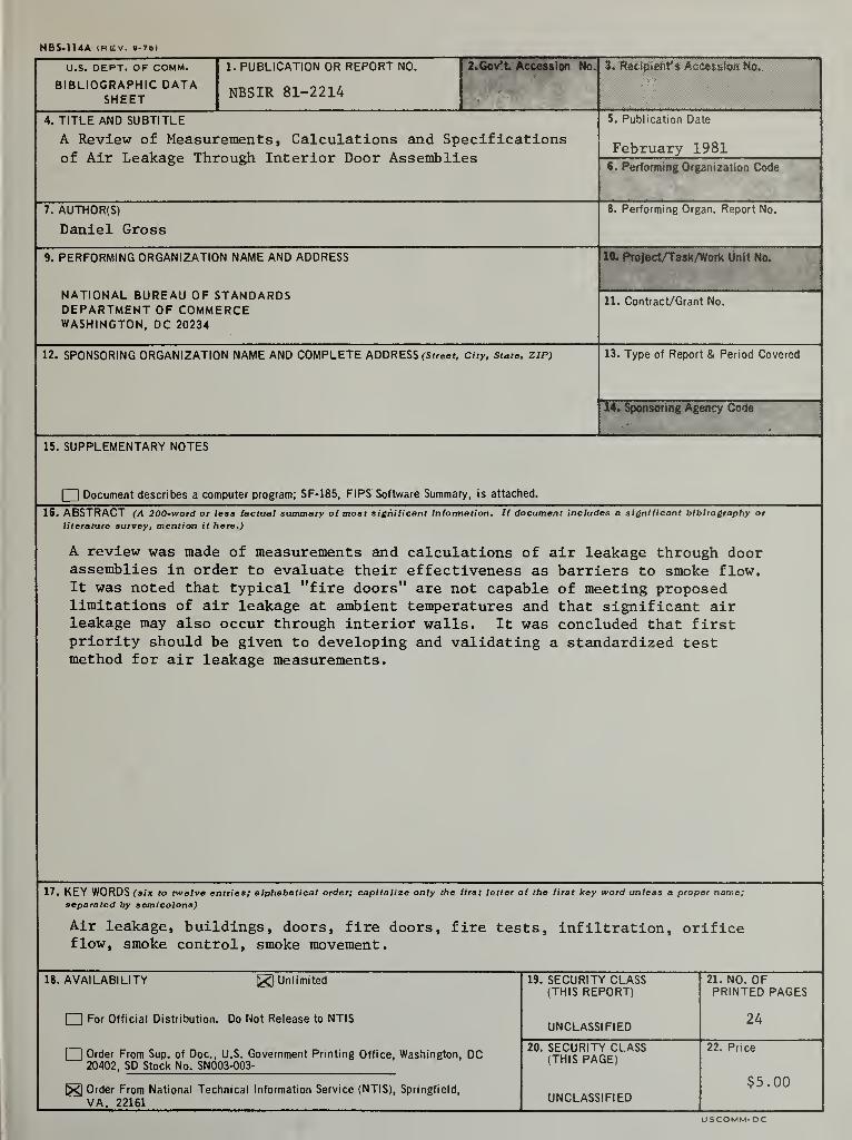
16. ABSTRACT (A 200*word or less tactual summary of most significant information* If document includes a significant bibliography or
literature survey, mention it here*)
A review was made of measurements eind calculations of air leakage through doorassemblies in order to evaluate their effectiveness as barriers to smoke flow.It was noted that typical "fire doors” are not capable of meeting proposedlimitations of air leakage at ambient temperatures and that significant airleakage may also occur through interior walls. It was concluded that firstpriority should be given to developing and validating a standardized testmethod for air leakage measurements.
17. KEY WORDS fsfx twelve entries; alphabetical order; capitalize only the first letter of the first key word unless a proper name;separated by semicolons)
Air leakage, buildings, doors, fire doors, fire tests, infiltration, orificeflow, smoke control, smoke movement.
18. AVAILABILITY ^Unlimited
I IFor Official Distribution. Do Not Release to NTIS
I IOrder From Sup. of Doc., U.S. Government Printing Office, Washington, DC20402, SD Stock No. SN003-003-
^ Order From National Technical Information Service (NTIS), Springfield,
VA. 22161
19. SECURITY CLASS(THIS REPORT)
UNCLASSIFIED
20. SECURITY CLASS(THIS PAGE)
UNCLASSIFIED
21. NO. OFPRINTED PAGES
24
22 . Price
$5.00
USCOMM-DC

I
i
I
I