Embed Size (px)
Citation preview
Fig. 1.
OAK RIDGENATIONAL LABORATORY MANAGED BY UT-BATTELLE
FOR THE DEPARTMENT OF ENERGY ORNL/TM-2009/137
A REVIEW OF MATERIALS FOR GASTURBINES FIRING SYNGAS FUELS
MAY 2009
T. B. Gibbons* and I. G. Wright
*Consultant

This report was prepared as an account of work sponsored byan agency of the United States Government. Neither the UnitedStates Government nor any agency thereof, nor any of theiremployees, makes any warranty, express or implied, or assumesany legal liability or responsibility for the accuracy, completeness,or usefulness of any information, apparatus, product, or processdisclosed, or represents that its use would not infringe privatelyowned rights. Reference herein to any specific commercialproduct, process, or service by trade name, trademark,manufacturer, or otherwise, does not necessarily constitute orimply its endorsement, recommendation, or favoring by theUnited States Government or any agency thereof. The views andopinions of authors expressed herein do not necessarily state orreflect those of the United States Government or any agencythereof.
DOCUMENT AVAILABILITY
Reports produced after January 1, 1996, are generally availablefree via the U.S. Department of Energy (DOE) Information Bridge.
Web site http://www.osti.gov/bridge
Reports produced before January 1, 1996, may be purchasedby members of the public from the following source.
National Technical Information Service5285 Port Royal RoadSpringfield, VA 22161Telephone 703-605-6000 (1-800-553-6847)TDD 703-487-4639Fax 703-605-6900E-mail [email protected] site http://www.ntis.gov/support/ordernowabout.htm
Reports are available to DOE employees, DOE contractors,Energy Technology Data Exchange (ETDE) representatives, andInternational Nuclear Information System (INIS)representatives from the following source.
Office of Scientific and Technical InformationP.O. Box 62Oak Ridge, TN 37831Telephone 865-576-8401Fax 865-576-5728E-mail [email protected] site http://www.osti.gov/contact.html
ORNL/TM-2009/137
Materials Science and Technology Division
A Review of Materials for Gas Turbines Firing Syngas Fuels
T. B. Gibbons* and I. G. Wright
*Consultant
Date Published: March 2007
Prepared for theU.S. Department of Energy
Fossil Energy Program
Prepared byOAK RIDGE NATIONAL LABORATORY
Oak Ridge, Tennessee 37831-6285Operated by
UT-Battelle, LLCfor the
U. S. DEPARTMENT OF ENERGYUnder contract DE-AC05-00OR22725


CONTENTSPage
LIST OF TABLES ............................................................................................................ v
LIST OF FIGURES ........................................................................................................ vii
EXECUTIVE SUMMARY ............................................................................................... ix
ABSTRACT .................................................................................................................... xi
1. INTRODUCTION ....................................................................................................... 1
2. OVERVIEW OF ISSUES ARISING FROM BURNING DIFFERENT (GASEOUS)FUELS GAS TURBINE ENGINES ...................................................................... 32.1 FUEL-RELATED DESIGN FACTORS ......................................................... 6
3. SOME CRITICAL ASPECTS OF CURRENT GAS TURBINE TECHNOLOGY ....... 13
4. THE CURRENT STATE OF THE ART IN MATERIALS TECHNOLOGY FOR GAS TURBINES ............................................................. 174.1 ALLOYS FOR HP BLADES AND VANES .................................................. 174.2 COATINGS FOR HP BLADES AND VANES ............................................. 244.3 COMBUSTOR MATERIALS ...................................................................... 284.4 DISC ALLOYS ........................................................................................... 294.5 PREDICTION OF MATERIALS PROPERTIES BY COMPUTER MODELING ............................................................................................... 30
5. IMPLICATIONS FOR MATERIALS SELECTION IN GAS TURBINES BURNING SYNGAS OR HYDROGEN ............................................................. 335.1 PERFORMANCE TARGETS ..................................................................... 335.2 FUEL-RELATED CORROSION ................................................................. 335.3 MATERIALS SELECTION ......................................................................... 36
6. SUMMARY OF MATERIALS NEEDS ...................................................................... 396.1 NEEDS RESULTING FROM THE PURSUIT OF HIGHER FIRING TEMPERATURES ..................................................................................... 396.2 EVOLVING NEEDS FROM CONSIDERATION OF HYDROGEN AS GAS TURBINE FUEL ............................................................................... 416.3 NEEDS RESULTING FROM CONCERNS ABOUT FUEL PURITY ......... 426.4 OVERALL SUMMARY OF MATERIALS NEEDS ...................................... 43
7. CONCLUSIONS ...................................................................................................... 45
8. ACKNOWLEDGMENTS ......................................................................................... 47
9. REFERENCES ........................................................................................................ 49
iii

LIST OF TABLES
Table Page
1 Some combustion properties of various fuels ................................................ 7
2 Firing temperatures for typical large gas turbines produced inthe USA ......................................................................................................... 13
3 Nominal compositions of advanced Ni-based airfoil alloys (allare single crystal alloy except where indicated) ............................................. 20
4 Compositions of typical sheet alloys (in weight percent) .............................. 28
5 Compositions of typical Ni-base disc alloys (in weight percent) ................... 30
6 U.S. DOE performance targets for gas turbines burning coal-derived gas ................................................................................................... 33
7 Ranking of overall materials needs ................................................................ 44
v


LIST OF FIGURES
Figure Page
1 Schematic illustration of a Siemens Model SGT5-8000H advanced gas turbine designed for combined cycle operation (from Siemens Power Generation ............................................... 3
2 Schematic block diagram of a gas turbine indicating theoverall gas flows ........................................................................................... 4
3 Schematic diagram of a gas turbine combustor .......................................... 5
4 Schematic block diagram of the turbine section, suggesting blade cooling ............................................................................ 5
5 Schematic block diagram of a gas turbine integrate withan air separation unit (ASU) for oxy-firing, suggesting theinterconnectivity of the gas streams ............................................................. 9
6 Stress for rupture in 1,000 h as a function of temperaturefor single-crystal alloys ............................................................................... 21
7 Creep rupture properties of single-crystal alloy CMSX-486 ........................ 21
8 An example of a second stage vane quadruplet cast as asingle-crystal .............................................................................................. 22
9 Comparison of trend in material temperature capability andturbine inlet temperature for aero-gas turbines ........................................... 24
10 Micrograph and schematic diagram showing the various layersin a TBC system ......................................................................................... 26
11 Combustor liner manufactured from ceramic composite ............................ 29
vii


EXECUTIVE SUMMARY
As a result of the considerable development effort carried out in the 1990’s, large
gas turbines (~250 mW) for power generation are now operating reliably and with high
availability ratings, in many parts of the world. However, since the price of natural gas
has risen significantly, the gas turbine combined-cycle power system does not have the
economic advantage over other generation technologies that applied a decade ago.
Now, with the drive for zero emission power generation systems, other opportunities
have opened up and, in particular, the coupling of a gas turbine combined-cycle system
with coal gasification offers some attractive potential advantages in the context of
reducing emissions. Furthermore, the use of coal-gasification technology will exploit the
large U.S. reserves of coal, with the potential for easing the dependence on imported
gas for power generation.
While there are many technical difficulties to be overcome in the successful
integration of coal gasification and gas turbine combined-cycle (IGCC) technology, the
emergence of large gas turbines as reliable, high-efficiency power generation systems is
a major advantage. Thus, in developing IGCC technology, the gas turbine will represent
a relatively mature technology at the heart of the generation system. There are,
however, challenges to be faced in order to accommodate the physical and chemical
differences of fuels other than natural gas. For example, the lower calorific value of
syngas results in a substantial increase in the mass flows through the engine, compared
with the combustion of natural gas and, while this will represent an increase in power
output, there will be a need to modify the engine design to accommodate the increased
gas flow. In addition, the higher hydrogen content of syngas (with its higher flame
speed) may lead to difficulties in control of the combustion process. Thus, there are
issues associated with different fuels that will have to be overcome in order to ensure
reliable gas turbine operation.
As far as materials are concerned, the review has shown that the materials
already available and/or currently under development for critical components in gas
turbines burning natural gas will be applicable to units operating in IGCC systems.
However since these materials have been developed for relatively clean environments,
the higher levels of sulfur, water vapor, and possibly particulates likely to be
encountered in syngas combustion will represent a potential limitation in terms of
component durability. Thus it will be necessary to initiate development efforts to provide
alloys with better corrosion resistance and coatings with enhanced corrosion and
ix

erosion resistance relative to the materials currently used in the cleaner natural gas
combustion environments. Because the high-temperature properties of the current
materials of choice in current high-performance gas turbines were obtained at the
expense of inherent resistance to sulfidation or hot corrosion attack, this will be a
significant task made all the more challenging if higher operating temperatures are
required for greater generation efficiency. In order to provide data on impurity levels to
guide the development effort, it will be important to have significantly better
characterization of the composition of the gas produced from gasification and clean-up
systems employed in IGCC. Finally, it will be necessary to demonstrate the operation of
a complete advanced syngas- or hydrogen-fired turbine, or at least of the key enabling
technologies, before the utility industry will accept such systems. Such a demonstration
phase will be expensive, so that consideration should be given to a collaboration should
be given to a collaborative effort, possibly a multi-national effort since the major gas
turbine manufacturers are international companies.
In addition there will be a continuing need for better long-term data to
characterize creep and fatigue performance of materials as a basis for improved design
and reliable operation, as well as better definition of the actual conditions, especially
temperature and temperature range, experienced by the key components in the hot gas
path. In view of the difficulties in obtaining physical measurements of such needed
parameters, increased use of computer modeling may be appropriate to predict
materials behavior. Further, the more demanding combustion conditions with syngas
may necessitate the evaluation of new materials (such as oxide dispersion-strengthened
alloys or ceramics) for combustor applications. However, final decisions in this regard
will depend on the precise chemistry of the combustion process, and the extent to which
changes are required in engine design. Finally, it will be necessary to demonstrate the
operation of a complete advanced syngas- or hydrogen-fired turbine, or at least of the
key enabling technologies, before the utility industry will accept such systems. Such a
demonstration phase will be expensive, so that consideration should be given to a
collaborative effort, possibly a multi-national effort since the major gas turbine
manufacturers are international companies.
The findings from this survey regarding materials needs for gas turbines burning
coal-derived syngas are presented in summary form, along with an indication of the
priority ranking for the individual requirements.
x
ABSTRACT
Following the extensive development work carried out in the 1990’s, gas turbine
combined-cycle (GTCC) systems burning natural gas represent a reliable and efficient
power generation technology widely used in many parts of the world. A critical factor
was that, in order to operate at the high turbine entry temperatures required for high
efficiency operation, aero-engine technology, i.e., single-crystal blades, thermal barrier
coatings, and sophisticated cooling techniques had to be rapidly scaled up and
introduced into these large gas turbines. The problems with reliability that resulted have
been largely overcome, so that the high-efficiency GTCC power generation system is
now a mature technology, capable of achieving high levels of availability.
The high price of natural gas and concern about emission of greenhouse gases
has focused attention on the desirability of replacing natural gas with gas derived from
coal (syngas) in these gas turbine systems, since typical systems analyses indicate that
IGCC plants have some potential to fulfil the requirement for a zero–emissions power
generation system. In this review, the current status of materials for the critical hot gas
path parts in large gas turbines is briefly considered in the context of the need to burn
syngas. A critical factor is that the syngas is a low-Btu fuel, and the higher mass flow
compared to natural gas will tend to increase the power output of the engine. However,
modifications to the turbine and to the combustion system also will be necessary.
It will be shown that many of the materials used in current engines will also be
applicable to units burning syngas but, since the combustion environment will contain a
greater level of impurities (especially sulfur, water vapor, and particulates), the durability
of some components may be prejudiced. Consequently, some effort will be needed to
develop improved coatings to resist attack by sulfur-containing compounds, and also
erosion.
xi


1. INTRODUCTION
The major efforts worldwide in the 1990's devoted to improvements in materials
and technology for gas turbines for electricity generation were driven by the demand for
high-efficiency units burning natural gas. This demand resulted from a combination of
factors that led to the gas turbine combined cycle (GTCC) system being the preferred
method of power generation. These factors included:
• a reliable supply of relatively cheap natural gas with low sulfur content;
• widespread deregulation (actual and planned) of the power generation industry;
and
• recognition of the need to reduce emissions of harmful greenhouse gases, and
CO2 in particular.
The increased deregulation of the industry in the USA and Europe provided
opportunities for independent power producers and owners of merchant plants to
contribute to the increased demand for electricity. The advantages of GTCC plant in this
regard were:
• low capital costs;
• construction time of about 24 months (compared with 36 months or more for a
coal-fired plant);
• increased generation efficiencies compared with coal-fired plants; and
• the ability to meet stringent emissions targets, e.g. NOx <10 ppm.
Thus, in the USA in the late 1990's, gas and steam turbines for combined cycle
operations represented over 60% of the annual orders for new power generating
capacity. This rapid build-up reflected the small margin of excess generating capacity
relative to demand resulting from the uncertainties associated with deregulation.1 One
consequence of this surge in the demand for GTCC plants was that various R&D
projects were initiated with the overall aim of increasing the operating efficiency of this
type of system to give a reduction in the cost of electricity. The most notable of these
was the Advanced Turbine Systems (ATS) project in the USA,2 which was a $400 million
effort with well-defined targets for improved efficiency (60%) and low emissions.
Similarly, the Moonlight Project in Japan3 involved collaboration between the major
turbine builders to develop an advanced gas turbine for power generation applications
and, more recently, the High-Temperature Materials 21 Project4 has provided an
opportunity for further developments in Ni-base superalloys. In Europe, the COST 501
project5 was focused on development of improved materials and coatings to enable the
1
production of components such as blades and vanes that would withstand the higher
firing temperatures associated with high-efficiency gas turbines burning natural gas.
The result of this development effort was that by the mid 1990's, large gas
turbines (around 250 MWe) firing natural gas were operating in combined cycle systems
giving around 400 MWe of power output with efficiency in excess of 55% in many cases,
and with very low NOx and SOx emissions. Also, advanced concepts were being
evaluated to give efficiencies of up to 60%. With the rising cost of natural gas (the price
generally tracks that of oil), attention has turned to the opportunities associated with the
production of gas from coal. One consequence has been an interest in improving the
technology of gas turbines burning low-Btu gas (syngas) with the aim of building on the
advances made with the current generation of engines to improve generating efficiency
with integrated gasification combined cycle (IGCC) plant. However, there are specific
problems associated with the combustion of low-Btu gas, which will require additional
development efforts both in specific aspects of turbine design, and in materials
performance in order to provide cost-effective solutions.
In the following sections of this review, some critical aspects of gas turbine
technology are outlined, the current status of materials for high-temperature components
is briefly described, and the implications for the combustion of syngas and hydrogen are
discussed.
2
2. OVERVIEW OF ISSUES ARISING FROM BURNING DIFFERENT (GASEOUS)FUELS GAS TURBINE ENGINES
Modern gas turbine engines are complex machines in which materials are used
to the limits of their capabilities in order to maximize the power and/or efficiency
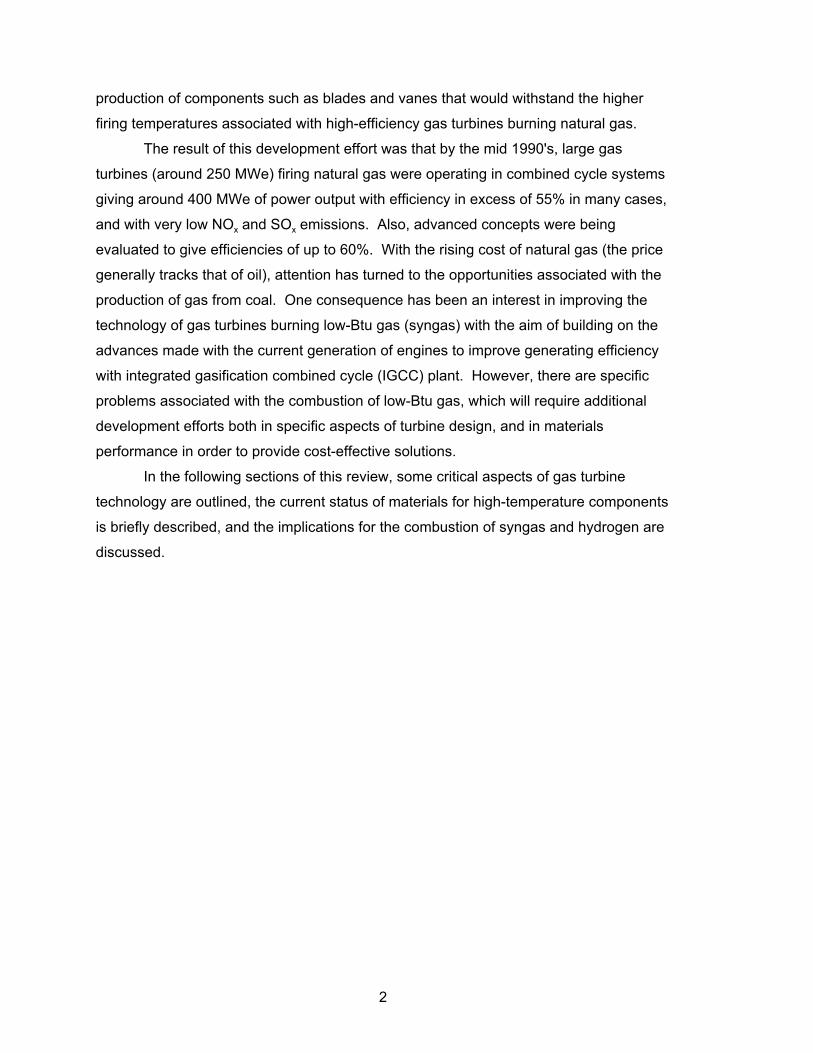
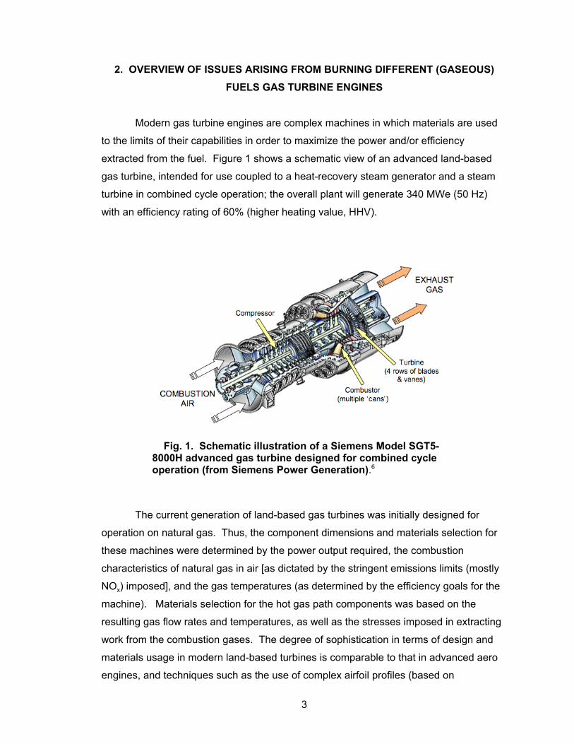
extracted from the fuel. Figure 1 shows a schematic view of an advanced land-based
gas turbine, intended for use coupled to a heat-recovery steam generator and a steam
turbine in combined cycle operation; the overall plant will generate 340 MWe (50 Hz)
with an efficiency rating of 60% (higher heating value, HHV).6
The current generation of land-based gas turbines was initially designed for
operation on natural gas. Thus, the component dimensions and materials selection for
these machines were determined by the power output required, the combustion
characteristics of natural gas in air [as dictated by the stringent emissions limits (mostly
NOx) imposed], and the gas temperatures (as determined by the efficiency goals for the
machine). Materials selection for the hot gas path components was based on the
resulting gas flow rates and temperatures, as well as the stresses imposed in extracting
work from the combustion gases. The degree of sophistication in terms of design and
materials usage in modern land-based turbines is comparable to that in advanced aero
engines, and techniques such as the use of complex airfoil profiles (based on
Fig. 1. Schematic illustration of a Siemens Model SGT5-8000H advanced gas turbine designed for combined cycleoperation (from Siemens Power Generation).6
3

computational fluid dynamics concepts) and active blade tip clearance control are
employed to maximize efficiency. Cooling of some of these components is mandatory,
since in places the temperature of the combustion gas exceeds the solidus temperature
of the strongest available alloys.
Figure 2 is a simplified, schematic block diagram of a generic gas turbine,
showing the major components, and indicating some of the gas flows. The bulk of the
air exiting the compressor is directed into the combustion zone at locations and in
amounts dictated by the requirements of the combustion process. The burner nozzle
and combustor can and liner are designed specifically to control the flame
characteristics of the fuel; cooling of the metallic combustor liner is achieved by flowing
the incoming air over its outer surfaces, as well as through appropriately-sized and
spaced holes, as indicated in Fig. 3. Air from the compressor also is used to cool some
of the hot gas path turbine components; typically air is taken from locations in the
compressor corresponding to the gas pressure at the particular location in the turbine
where the coolant is needed. Figure 4 illustrates air cooling of the first two rows of
blades and vanes in a four-stage turbine. Air from the compressor may be routed
through the turbine discs into the blades, where cooling is accomplished by convection,
direct impingement of air onto the inside surfaces of the airfoil walls, or released through
holes in the trailing edge and blade tip. In more advanced designs, the air eventually is
directed though carefully sized and shaped holes to provide a film of a cooling air over
the external surfaces of areas of particular concern, such as the pressure (concave)
surfaces.
Fig. 2. Schematic block diagram of a gas turbine indicatingthe overall gas flows.
4

Fig. 3. Schematic diagram of a gas turbine combustor.
Fig. 4. Schematic block diagram of the turbine section,suggesting blade cooling.
5

2.1 FUEL-RELATED DESIGN FACTORS
There are differences in composition between natural gas and syngas that result
in differences in their combustion characteristics. The fuel gas generated by gasification
of coal consists primarily of H2 and CO, along with smaller amounts of CH4 and
higher-order hydrocarbons, CO2, and H2O; the level of N2 in syngas can vary from low to
high, depending on whether the gasifier is oxygen- or air-blown. Also, there may be
impurities in syngas not typically found in natural gas, which include sulfur, alkali species
and solid particles at levels that depend on the original coal, the gasification process,
and the characteristics of the gas clean-up processes employed. As a result, the
properties of syngas that relate to its combustion characteristics can vary considerably.
In simple terms, some key issues to be considered when using syngas or hydrogen
rather than natural gas (taken here as essentially CH4) to fire a gas turbine are:
• Syngas (and hydrogen) have significantly higher laminar flame speeds than
natural gas, giving rise to flame stability issues. Laminar flame speed (sL) is the
rate at which a flame can propagate in a combustion mixture. If the flame speed
is lower than the flow rate of the reactants, the flame may detach from the
burner, whereas a flame speed higher than the flow rate of the reactants has the
risk that the flame may flash back into the burner. Note that the value of sL for
methane (assumed here to be the same as natural gas) shown in Table 1 is
only approximately 1/3 that of a 50:50 H2:CO mixture (intended to simulate
syngas),7 and that the flame speed of undiluted hydrogen is at least five times
that of methane/natural gas. The flame speed of H2/CO mixtures decreases as
the amount of dilution (CO) is increased, such that a value of sL equivalent that
of natural gas can be achieved if the H2/CO ratio of ‘syngas’ is increased to 5:95
(Table 1). There is some effect of temperature on flame speed, and it was
found that the measured and predicted values of sL tended to diverge at
temperatures greater than 127EC.7
• The levels of water vapor in the combustion gas from syngas (and hydrogen)
are higher than in natural gas, and result in changes in the heat transfer
properties of the flame, with implications for the ability to maintain adequate
cooling of key components; high water vapor levels also may have detrimental
effects on component durability.
6

• The combustion of syngas probably will result in higher levels of unburned
carbon than natural gas, which affects the luminosity flame hence heat transfer
to the cooled components.
• The calorific value (CV) of syngas from an oxygen-blown gasifier typically is
approximately 1/3 that of natural gas (on a molar or volume basis), whereas that
from an air-blown gasifier is lower (~1/10); also, the CV of hydrogen is
approximately 0.3 times that of methane or natural gas on a volume basis (see
Table 1). These large differences lead to differences in the relative gas flows in
the turbine when compared on the basis of constant power, and have
implications for combustor design, flame stability and increased heat transfer to
the combustor can and airfoils.
Table 1. Some combustion properties of various fuels
Fuel Adiabatic flame T (EC)
Calorific value (HHV)
Maximum adiabaticlaminar flame speed
Air Oxygen kJ/kg kJ/m3 cm/s
CH4 19478–25009
33279 55,5309 39,8209 247–408
Natural Gas 43,0009
H2 21108–26579
35529 139,00010–141,7909
13,0009 210–2407; 3208
CO 21128 558
Syngas (air-blown)
4,500–5,50011
Syngas (O2-blown)
9,000–13,00011
H2/CO (50-50) 70–1157,a
H2/co (5:95) 20–407,a
C3H8 25419 33689 50,20010–50,3509
101,0009
C8H18 25509 34819
Diesel oil 44,80010–45,5009
Conv. gasoline 46,50010–47,3009
aDepending on equivalence ratio.
7

• The corrosion potential of combusted syngas is expected to be greater than for
natural gas, based on its increased water vapor content, and the likelihood of the
presence of alkali and sulfur levels near the maximum typically allowed in turbine
fuel specifications.12 The likely levels of condensable salts will depend on the
details of the gas clean-up processing employed, but the possibility is allowed that
they could approach the usual trigger points for initiation of deposition on some of
the turbine stages. In fact, the higher fuel-to-air ratio in syngas combustion makes
it likely that these trigger points will be reached with lower impurity levels in the
fuel, with the result that the potential for hot corrosion in the turbine may be
increased (depending on the range and amount of impurities present).
• Though significant emphasis in syngas clean-up is placed on particulate removal,
until reliable data are available from sustained operation of IGCC plants, the
possibility of erosive damage to the first stage vanes and blades should be
acknowledged. Also, although stringent control of the combustion process will be
practiced for emissions abatement, the formation of carbon-rich particles (and
resulting erosion damage) also should not be overlooked.
• Control of the flue gas exit temperature may be more difficult than with natural
gas, which may present problems for the downstream heat-recovery steam
generator.
The differences in such properties among natural gas, syngas, and hydrogen
highlight the need to evaluate the implications for design and operation of gas turbine
combustion systems intended to operate on different fuels. Figure 5 shows the relative
gas flows in a turbine (using the schematic layout from Fig. 2), and is intended to provide
some indication of the interdependence among the air and fuel flows; in addition, the
case of coupling the gas turbine with an air separation unit (ASU) to permit oxygen-
augmentation of the combustion air is considered. Note that the gas turbine compressor
is assumed to supply air not only for combustion (stream A1), but also for cooling of hot
section components (A2, A3); compressor air also may be supplied to the gasifier (stream
A4). There is also the possibility that for oxy-firing, the air feed for the ASU would be
provided by the turbine compressor (stream A5). The flow of combustion air (and/or
oxygen) and fuel (F) are related by the combustion characteristics required by the
turbine power and emissions specifications. Where the fuel requires dilution to avoid
explosive mixtures, or to control NOx formation, the gas flow in the combustor will
include N2 or steam additions, which have been omitted from this discussion for the sake
of simplicity.
8

A further important issue is that the temperatures of hot gas path components
(such as first stage vanes and blades) must be tightly controlled to prevent them from
exceeding their strength capability limits. Thus, the cooling provided by streams A2 and
A3 is critically important, and must be matched to the heat transfer associated with the
combustion of each fuel (or the combustion temperature must be decreased to allow the
temperature of the critical vanes and blades to be maintained below some critical level).
This is a problem when switching fuels, since for a given turbine design, the values of
the flow rates of streams A2 and A3 are not readily variable. In terms of the turbine cycle,
since the cooling air streams A2 and A3 do not contribute to the combustion process,
they detract from the overall efficiency of the engine, and so should be minimized. Other
sources of coolant have been considered, such as steam cooling by integration of the
gas turbine with the steam circuit in a combined cycle13 and, for oxy-firing, the nitrogen
from the ASU might be used for this purpose, thus possibly reducing the air flow in
streams A2 and A3.
These simple considerations suggest that different compressor and turbine flows
will be needed to allow the optimized use of different fuels, in order to accommodate the
differences arising from, for example, variations in the CV of natural gas, syngas and
hydrogen, and adjustments of other flows to provide adequate cooling. While
quantification of the flow streams suggested in Fig. 5 for any fuel is not straightforward,
the following simplified argument is presented as a means for obtaining a rough
Fig. 5. Schematic block diagram of a gas turbine integratewith an air separation unit (ASU) for oxy-firing, suggestingthe interconnectivity of the gas streams.
9
approximation of the magnitude of the changes expected in flow rates in key areas, due
to combusting syngas or hydrogen in a gas turbine designed for natural gas.
The gas flow through the combustor is composed of the flows of combustion air
(A1) and fuel (F), and these two components are related by the molar proportions of the
reacting species, and the air-to-fuel ratio (or overall stoichiometry, η). The continuation
of natural gas (CH4) is considered to involve:
CH4 + 2O2 + (8N2) = CO2 + 2H2O + (8N2) (1)
On the basis on one mole of methane combusted, the molar (volume) flow
through the combustor is (1+1η), and through the turbine [3+(8η+2η-2)]+(A2+A3). For an
air/fuel ratio of 20, and the total cooling air flow extracted from the compressor is
0.05 A1, the molar flows through the combustor and turbine are 201 and 211,
respectively, so that the turbine flow rate is approximately 4% greater than that through
the combustor.
For syngas from an oxygen-blown gasifier, assuming that the gas consists of
1 part CH4 + 2 parts N2 (CV = 1/3 that of natural gas, and 1 mole of natural gas is
represented by CO + 3H2), the combustion process can be represented by:
CO + 3H2 + 2O2 + 8N2 (air) + (8N2 from gasifier) = CO2 + 3H2O + 10N2 (2)
The combustor and turbine flows become (12+10η), and [(12+8η+2η-2.5)+(A2+A3)],
respectively, and for η = 20 and (A2+A3) = 0.05A1, the molar flows are 212 and 219.5
respectively, an increase for the combustor of 5% compared to natural gas, and 4% for
the turbine.
For the stoichiometric combustion of hydrogen in oxygen (assuming that the CV
of hydrogen = 1/3 CH4, Table I):
3H2 + 3/2O2 = 3H2O + 6N2 (coolant) (3)
The combustor and turbine molar flows for the nominally same turbine power would be
4.5 and [3+(A2+A3)], respectively, (assuming that all of the turbine cooling could be
accomplished by the nitrogen component of stream A5, as suggested in Fig. 5). The
combustor and turbine flows would be 4.5 and 9, respectively. Compared to natural gas,
these flows represent a significant mismatch in combustor and turbine sizes.
10
Overall, it is suggested that a syngas-fueled machine would experience higher
gas flows through the combustor and turbine than when burning natural gas, and that
these would increase with decreasing CV of the syngas. In the case of a hydrogen-fired
turbine, the gas molar flows through the combustor and turbine will be significantly
decreased compared to firing with natural gas. It is clear from these simple arguments
that there are significant implications for the design of the turbine that must be
addressed especially for the combustor, from the desire to burn different fuels. Some
accommodation of the mismatches in flow rates among the fuels can probably be made
by the inclusion of variable guide vanes in the compressor or turbine first stages, or by
changing the shape of the first-stage turbine vane to reduce the pressure drop resulting
from increased flows. However, it is not obvious that the differences in combustion
characteristics can be accommodated in a single combustor design that can maintain
the desired emissions values of, for instance, NOx.
11


3. SOME CRITICAL ASPECTS OF CURRENT GAS TURBINE TECHNOLOGY
Prior to the rapid build-up in GTCC generating capacity, gas turbines for power
generation had chiefly been used in simple-cycle operations for “peak lopping”
applications.14 In this case, the rapid start-up capability of the gas turbine was a major
advantage and, in view of the short operating time, there was no great requirement for
high efficiency. Consequently, these engines used relatively low firing temperatures
compared with the maximum capabilities of aero-engines, and were much less
sophisticated in design, so that relatively low-strength alloys could be used for
components such as blades and vanes, and cooling technology was generally not
required. Some of the smaller engines were derivatives of existing aero-engines, which
were derated for land-based application.
By comparison, the development of large (250 MWe) gas turbines operating as
base-loaded units for power generation in GTCC systems required a new approach to
materials and component design in order to cope with the higher firing temperatures
consistent with the demand for high efficiency and low cost of electricity. Some typical
firing temperatures in advanced land-based gas turbines from the major manufacturers
are shown in Table 2, along with calculated efficiency values.15
Table 2. Firing temperatures for typical large gas turbines produced in the USA
EngineRotor inlet
temperature(EC)
Power output(MWe)
Predicted efficinecy(%)
Westinghouse 501G 1426 240 58
Siemens V84/3a 1310 170 57
Alstom GT24/26 1240 188/281 57
General Electric 7FA 1290 150 55
As a result, technology that previously had been used only in aero-engines was
rapidly adopted for GTCC application. This included the use of advanced casting
processes for producing blades and vanes containing complex cooling passages
associated with sophisticated cooling techniques, and the introduction of improved
coating technology (including thermal barriers) to give effective protection at the highest
temperatures. These requirements represented a considerable technical challenge to
the manufacturers and component suppliers and, not surprisingly, there were difficulties
13

(particularly with the earlier engines) so that reliability, and hence availability, was poor
for some engine designs. However, with modifications and detailed improvement in
design, these difficulties were gradually overcome, so that (it is claimed) current variants
of these engines perform well, with high levels of availability.
Consequently, the current generation of land-based gas turbine engines has
reached a certain level of technological maturity, and can be characterized by the
following features:
• extensive use of thermal barrier coatings (TBCs) or ceramic tiles in the combustor
lining;
• single-crystal (SC) blades and vanes for the first stage of the high-pressure
turbine, operating with metal surface temperatures of 950EC or more, and with
complex patterns of cooling holes to maintain desired cooling levels while
minimizing the amount of cooling air required;
• highly oxidation-resistant metallic coatings (usually NiCrAl-base) on blades, vanes
and combustor surfaces;
• extensive application of TBCs on the first stage blades and vanes, with a ΔT
capability of the order of 150EC to enable desired cooling levels to be achieved;
• directionally-solidified (DS) blades and vanes for the remaining rows in the
high-pressure turbine, operating at somewhat lower temperatures; and
• Ni-base alloys (rather than ferritic steels) in some cases, for high-pressure turbine
discs.
Despite the considerable experience with these advanced materials in aero-engine
applications, transfer of the technology to the much larger, land-based turbines was not
a straightforward matter, and involved a substantial development effort by the
manufacturers and component suppliers. Difficulties arose in the following areas:
• production of SC blade castings, where difficulties in maintaining control of the
solidification process as the size of the components increased resulted in defects
such as low-angle boundaries and ‘stray’ grains;
• misalignment of the columnar grains in DS components because of the increase
in component size;
• inadequate coating and processing methods for both oxidation-resistance and
thermal barriers; and
• processing of large disc forgings of Ni-base alloys.
Solutions were developed for most of these problem areas, by both modification
to alloy and coating compositions, and by improvements in processing methods, for
14
example, casting and coating deposition techniques. As far as improvements in
processing were concerned, computer-modeling methods for casting and forging were
instrumental in defining optimum conditions. An important outcome of these
improvements was that yields, particularly of SC castings, were greatly increased,
contributing to decreased costs.2
Thus, it is apparent that the introduction of advanced gas turbine technology to
the power generation business was a high-risk endeavor, with severe financial
consequences resulting from the effort required to overcome problems that emerged
during commercial operation of some of the earlier engines. Now, however, these
machines appear to be operating reliably, and the technology has reached a level of
maturity that can provide a basis for the development of high-efficiency engines suitable
for application in IGCC systems. It is acknowledged that modifications will be required to
achieve the desired efficiencies and emissions reduction when fired by syngas, and
some changes in design will be necessary to accommodate differences in combustion
characteristics and mass flow. In this regard, modifications in combustor design will
probably represent one of the more challenging areas for improvements in materials
selection and application.
15


4. THE CURRENT STATE OF THE ART IN MATERIALS TECHNOLOGY FOR GAS TURBINES
4.1 ALLOYS FOR HP BLADES AND VANES
For some years now these components, which are subjected to the highest
temperatures and, in the case of blades, the highest stresses in the turbine, have been
manufactured from SC castings of high-strength, Ni-based superalloys. The concept of
directional solidification (DS) began to be developed in the 1960’s to improve ductility
and also low-cycle fatigue performance by eliminating the transverse grain boundaries,
which usually were associated with fracture. In the early days, the process was limited
to small components in military engines, but the technology has developed to the stage
where the relatively large blades and vanes used in gas turbines for electric power
generation in either simple- or combined-cycle mode are routinely produced as single
crystals. The high rotor-inlet temperatures (RITs) necessary to obtain the high
efficiencies required to give relatively low generation costs result in surface
temperatures for hot gas path components that make castings in SC superalloys
essential for the blades and vanes in the first stage (and possibly second stage) of the
turbine. The advantages of SC castings have been well documented16 and include:
• improved creep and stress rupture properties;
• enhanced fatigue performance (for both low-cycle fatigue and thermo-mechanical
fatigue);
• good oxidation resistance (particularly for the 2nd generation SC alloys); and
• increased reliability of coatings.
In parallel with the development of casting technology, there has been a
substantial effort aimed at developing alloy compositions specifically tailored for casting
as SCs. The emphasis has been to optimize the alloy composition in the absence of
grain boundary-strengthening additions (such as C, B and Zr). One consequence of
omitting these additions has been to raise the incipient melting point, thereby allowing
heat treatments to achieve full solutioning of the γ' strengthening phase, and so increase
the volume fraction that can be precipitated on subsequent heat treatment, hence
maximizing strength at high temperature. Further improvements were obtained by the
addition of rhenium, which had a major effect in increasing the strength of the alloy,
while necessitating a reduction in the content of chromium. The resulting series of
advanced superalloys for SC components has been characterized as 1st-, 2nd-, or 3rd-
17

generation alloys, largely on the basis of the rhenium content. Recently, further
improvements in creep strength have been claimed as a result of additions of iridium and
ruthenium together with rhenium; while these alloys tentatively have been characterized
as 4th- and 5th-generation, respectively there is little sign that they will be used
commercially.17 The compositions of some typical alloys representative of each
development phase (or generation) are given in Table 3.
Only alloys classed as 2nd- and 3rd-generation are currently in use in gas turbines;
but factors such as the high cost of Re have led to reduced interest in the 3rd generation
alloys. Whether or not the more advanced alloys proceed to commercialization depends
on further work to characterize properties and long-term structural stability. As a result
of the work to optimize compositions, and the development of multi-step heat treatments
to optimize the phase content, all of the SC alloys are characterized by very high
volumes of the γ' strengthening phase (60-70%), and therefore exhibit incremental
increases in strength at high temperature. For example, the experimental alloy TMS162
(developed in the High-Temperature Materials 21 project in Japan4) exhibits a rupture
life of about 1,250 h at 1100EC and 137 MPa, which is claimed to be the highest
temperature capability ever recorded for a Ni-based superalloy.
A typical measure of the performance of a superalloy is its creep-rupture
properties. In the examples of the stress for rupture in 1,000 h as a function of
temperature, shown in Fig. 6,18 it will be seen that the new, “5th” generation SC alloy
TMS 162 has a temperature advantage of about 40°C compared with the widely-used
(2nd generation SC) alloy CMSX-4. However, it remains to be seen whether this
temperature advantage will be sustained at longer times, that is, in conditions more
representative of service. Thus, longer-term creep data will be essential in order to
provide a reliable measure of the improvement in temperature capability of the new
alloys.
One of the major disadvantages of SC technology has been sensitivity to defects
such as ‘stray’ grains and low-angle grain boundaries, which can seriously degrade
performance. Consequently, casting yields were frequently poor in the early days of
producing SC castings of large components for power generation gas turbines.
However, subsequent developments in SC alloy compositions and casting technology to
increase casting yield and reduce production costs has resulted in alloys with somewhat
lower strength, but greater tolerance to casting defects. An early contender in this
category was CMSX-186, which was initially produced as a polycrystalline, DS alloy.
The SC variant (which has additions of hafnium and boron to reduce the sensitivity to
18

the presence of casting defects such as low-angle grain boundaries) can be used in the
as-cast condition, further contributing to a reduction in cost compared with the highest-
strength SC alloys.
Further progress18 has led to the development of alloys more adapted to large
castings, such as CMSX-486, which also has additions of hafnium and boron, but
otherwise is similar in composition to the second-generation alloy CMSX-4 (see Table
3). An additional advantage of this alloy is that good high-temperature properties were
obtained with a double aging treatment after casting, thereby eliminating the risk of
localized recrystallization during solution heat treatment. In this case (as can be seen
from Fig. 6), the temperature capability is inferior to that of CMSX-4 by about 60°C, at
least on the basis of the stress for rupture in 1,000 h. However, an important point is
that long-term creep rupture data are available for this alloy, as shown in Fig. 7. It is
evident that, in these testing conditions, the alloy showed good stability for longer than
10,000 h at temperatures between 982 and 1093EC. The alloy has good castability, and
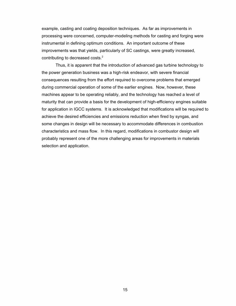
has been used for components such as multi-vane segments (Fig. 8), where defects
such as low-angle boundaries can occur.
19

Table 3. Nominal compositions of advanced Ni-based airfoil alloys (all are single crystal alloyexcept where indicated)
Alloy Composition, weight percent
Cr Co W Mo Re Ta Al Ti Hf Others
Conventionally Cast
IN738LC 16 8.2 2.6 1.7 1.8 3.5 3.5 0.11C;0.01B;0.03Zr
IN792 13 9 3.9 2 3.9 3.2 4.2 0.21D;0.02B;0.1Zr
IN939 23 19 1.9 1.3 1.9 3.7 1.1Nb;0.15C;.01B;0.1Zr
Directionally Solidified
MARM27LC 9 10 10 0.6 3.0 5.5 1.0 1.5 0.15C;0.15Bl9,93Zr
GTD-111 14 9.5 3.8 1.5 2.8 3 4.9 0.15 0.1C;0.01B;0.15Hf
ExA17a 12 9 3.5 1.8 2-3 4 3.4 3.9
TMD103a 3 12 6 2 5 6 6 0.1 0..;0.015B
Single Crystal
PWAl480 (1st gen) 10 5 4 12 5 1.5
PWA1483 (1st gen) 12.8 9 3.8 1.9 4 3.6 4
René N4 (1st gen) 9 8 6 2 4 3.7 4.2 0.5Nb
SC16 (1st gen) 16 3 3.5 3.5 35
PWA1484 *2nd gen) 5 10 6 1.9 3 5.6 0.1 8.7Nb
René N5 (2nd gen) 7 8 5 2 3 7 6.2 0.2
CMSX-4 (2nd gen) 6.5 10 6 0.6 3 6 5.6 1.0 0.1
CMSX-186 (2nd gen)b 6 9.3 8.4 0.5 2.9 3.4 5.7 0.7 1.4
CMSX-486 (2nd gen)b 5 9.3 8.6 0.7 3 4.5 5.7 0.7 1.2
René N6 (3rd gen) 4.2 12.5 6 1.4 5.4 5.8 0.15 7.2Nb;0.05C;0.004B;0.01Y
CMSX-10 (3rd gen) 2 3 5 0.4 6 8 5.7 0.2 0.03 0.1Nb
TMS75 (3rd gen) 3 12 6 2 5 6 6 0.1
MX4/PWA1497 (“4th” gen) 2 16.5 6 2 6 8.3 5.6 0.05 3Ru;0.03;0.04B;0.01Y
TMS139 (“4th” gen) 2.9 5.8 5.8 2.9 4.9 5.5 5.8 0.1 3Ir
TMS162 (“5th” gen) 2.9 5.8 5.8 3.9 4.9 5.6 5.8 0.1 6Ru
TMS196 (“5th” gen) 4.6 5.6 5.0 2.4 6.4 5.6 5.6 0.1 5Ru
aDevelopmental alloy. bRevisited 2nd generation.
20

Fig. 6. Stress for rupture in 1,000 h as a function oftemperature for single-crystal alloys (after Harris and Wahl,ref. 18).
Fig. 7. Creep rupture properties of single-crystal alloyCMSX-486 (after Harris and Wahl, ref. 18).
21
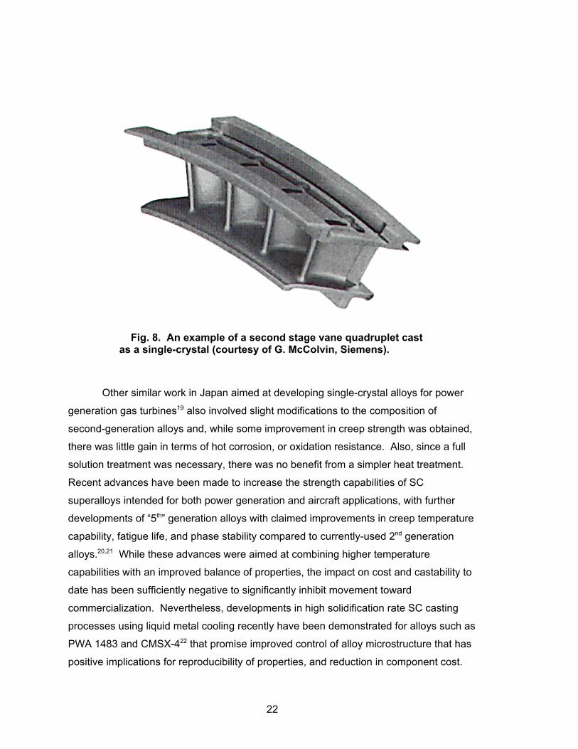
Other similar work in Japan aimed at developing single-crystal alloys for power
generation gas turbines19 also involved slight modifications to the composition of
second-generation alloys and, while some improvement in creep strength was obtained,
there was little gain in terms of hot corrosion, or oxidation resistance. Also, since a full
solution treatment was necessary, there was no benefit from a simpler heat treatment.
Recent advances have been made to increase the strength capabilities of SC
superalloys intended for both power generation and aircraft applications, with further
developments of “5th” generation alloys with claimed improvements in creep temperature
capability, fatigue life, and phase stability compared to currently-used 2nd generation
alloys.20,21 While these advances were aimed at combining higher temperature
capabilities with an improved balance of properties, the impact on cost and castability to
date has been sufficiently negative to significantly inhibit movement toward
commercialization. Nevertheless, developments in high solidification rate SC casting
processes using liquid metal cooling recently have been demonstrated for alloys such as
PWA 1483 and CMSX-422 that promise improved control of alloy microstructure that has
positive implications for reproducibility of properties, and reduction in component cost.
Fig. 8. An example of a second stage vane quadruplet castas a single-crystal (courtesy of G. McColvin, Siemens).
22
A characteristic of all the alloys discussed above is that, while the compositions
have been optimized for high-temperature creep strength, the main environmental threat
considered was that from high-temperature oxidation. These alloys rely on an inherent
ability to form a protective scale based on alumina and, since the alloy content of
chromium is relatively low, they will have poor resistance to sulfidation (hot corrosion) if
sulfur and alkali levels in the fuel are higher than those in natural gas. Accordingly, it
may be necessary to develop a new range of higher-chromium alloys with good creep
resistance for operation in syngas environments. This will be a challenging requirement,
because lowering the chromium level has been critical to the success of the
development of the high-strength levels in SC alloys.
Since not all gas turbines are required to operate at the highest RIT, and not all
components in the engine (for example, the later stages of the turbine) are exposed to
the highest temperatures, there is a continuing effort to improve the performance of DS
alloys with columnar-grained microstructures. One consequence of the lower
temperatures experienced by these components is that they operate in a regime where
they are susceptible to Type I hot corrosion23 if condensable sulfate impurities are
present in the combustion gas. Type I hot corrosion involves sulfidation attack from
deposits of molten salts (typically based on Na2SO4). The guiding principle in alloy
selection for resistance to this form of corrosion is to maximize chromium content; alloys
specifically designed to combat hot corrosion, such as IN738, IN939 and GTD-111,
contain 14-23 wt % chromium (Table 3). Thus, a logical goal for improved DS alloys is
to achieve corrosion and oxidation resistance equivalent to IN939, and creep strength
superior to that of alloy MARM247 (which has been widely used as a blade and vane
material in large gas turbines). The emphasis of recent work24 was on the concept of
adding rhenium to alloys with relatively high chromium contents (around 10%), and the
outcome was an experimental alloy ExA17 with good resistance to hot corrosion and
oxidation and, that was (following a homogenizing heat treatment) substantially free of
harmful phases that would result in structural instability. Early results from creep tests
suggest that the improvement in creep strength will be equivalent to an increment in
temperature capability of about 30EC relative to the performance of the standard
MARM247LC.
A somewhat different approach has been adopted in Japan:25 in this case, 5%
rhenium was added to an alloy with a low content of chromium and, in relatively
short-term tests (6,000 h), the creep performance of the alloy (TMD103) approached that
of the SC alloy TMS75. The compositions of these new alloys are included in Table 3,
23

along with that for MARM247LC for comparison. Thus, it appears that there remains
some potential for further improvement in the performance of DS alloys.
These developments should be seen in the context of the effort to push the
superalloys to the limit of their capabilities in the absence of any likely successor
material at least in the foreseeable future.
4.2 COATINGS FOR HP BLADES AND VANES
The high rotor inlet temperatures of current land-based gas turbines are achieved
by a combination of cooling processes, usually using air bled from the compressor, and
the application of TBCs to provide thermal insulation. Together, these technologies are
used to maintain maximum metal temperatures at around 1000EC (while RITs approach
1450EC). This relationship is illustrated in Fig. 9.26 The effort to bridge the increasing
gap between alloy creep strength and gas temperature has led to the development of
innovative combinations of cooling technology and TBCs to enable continued
improvements in gas turbine performance.
Fig. 9. Comparison of trend in material temperaturecapability and turbine inlet temperature for aero-gas turbines(after Walston, ref. 26).
24
Initially, TBCs were used to give an extra measure of protection (as well as
enhancement of component life) for an existing design but, increasingly, components
have been designed to take some advantage of the temperature decrement provided by
the coating system. Increasingly, the full functioning of the TBC is essential for the
engine to meet performance targets. In order to achieve this objective, an
unprecedented level of reliability and consistency of performance is required.
Consequently, a major effort is being devoted worldwide to understanding the failure
mechanisms of TBCs, with the aim of achieving the degree of predictability needed to
allow the confident use of mechanism-based lifting models, with the hope of eventually
attaining the goal of being able to take full advantage of the temperature decrement
provided by a TBC in engine design. In parallel with this development, non-destructive
evaluation (NDE) techniques are being devised to enable the condition of the coating to
be monitored (preferably in-situ) to provide early indication of coating deterioration.2
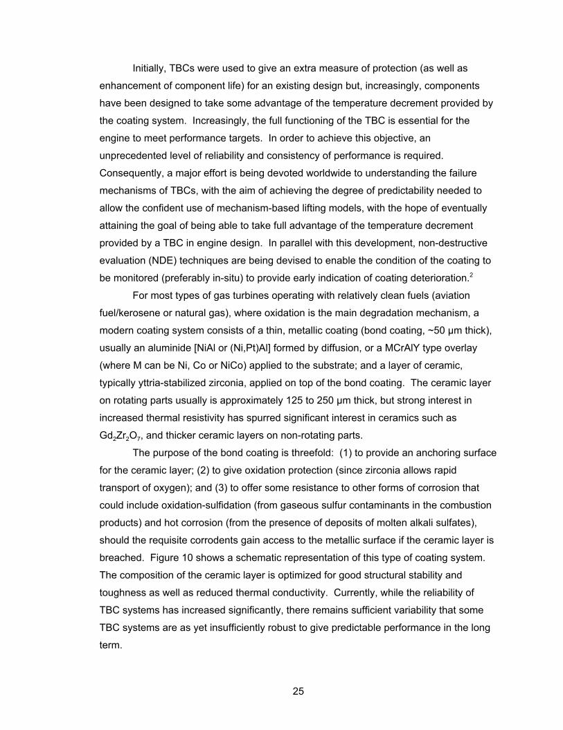
For most types of gas turbines operating with relatively clean fuels (aviation
fuel/kerosene or natural gas), where oxidation is the main degradation mechanism, a
modern coating system consists of a thin, metallic coating (bond coating, ~50 µm thick),
usually an aluminide [NiAl or (Ni,Pt)Al] formed by diffusion, or a MCrAlY type overlay
(where M can be Ni, Co or NiCo) applied to the substrate; and a layer of ceramic,
typically yttria-stabilized zirconia, applied on top of the bond coating. The ceramic layer
on rotating parts usually is approximately 125 to 250 µm thick, but strong interest in
increased thermal resistivity has spurred significant interest in ceramics such as
Gd2Zr2O7, and thicker ceramic layers on non-rotating parts.
The purpose of the bond coating is threefold: (1) to provide an anchoring surface
for the ceramic layer; (2) to give oxidation protection (since zirconia allows rapid
transport of oxygen); and (3) to offer some resistance to other forms of corrosion that
could include oxidation-sulfidation (from gaseous sulfur contaminants in the combustion
products) and hot corrosion (from the presence of deposits of molten alkali sulfates),
should the requisite corrodents gain access to the metallic surface if the ceramic layer is
breached. Figure 10 shows a schematic representation of this type of coating system.
The composition of the ceramic layer is optimized for good structural stability and
toughness as well as reduced thermal conductivity. Currently, while the reliability of
TBC systems has increased significantly, there remains sufficient variability that some
TBC systems are as yet insufficiently robust to give predictable performance in the long
term.
25
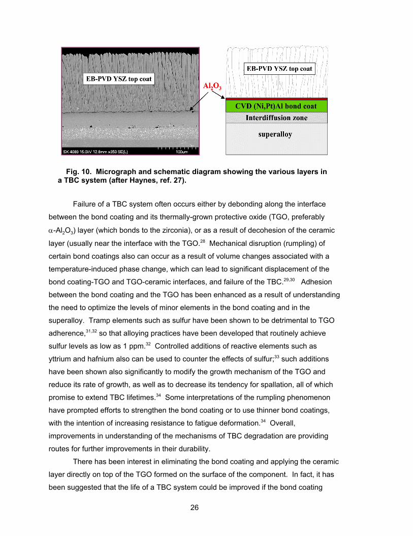
27 Failure of a TBC system often occurs either by debonding along the interface
between the bond coating and its thermally-grown protective oxide (TGO, preferably
α-Al2O3) layer (which bonds to the zirconia), or as a result of decohesion of the ceramic
layer (usually near the interface with the TGO.28 Mechanical disruption (rumpling) of
certain bond coatings also can occur as a result of volume changes associated with a
temperature-induced phase change, which can lead to significant displacement of the
bond coating-TGO and TGO-ceramic interfaces, and failure of the TBC.29,30 Adhesion
between the bond coating and the TGO has been enhanced as a result of understanding
the need to optimize the levels of minor elements in the bond coating and in the
superalloy. Tramp elements such as sulfur have been shown to be detrimental to TGO
adherence,31,32 so that alloying practices have been developed that routinely achieve
sulfur levels as low as 1 ppm.32 Controlled additions of reactive elements such as
yttrium and hafnium also can be used to counter the effects of sulfur;33 such additions
have been shown also significantly to modify the growth mechanism of the TGO and
reduce its rate of growth, as well as to decrease its tendency for spallation, all of which
promise to extend TBC lifetimes.34 Some interpretations of the rumpling phenomenon
have prompted efforts to strengthen the bond coating or to use thinner bond coatings,
with the intention of increasing resistance to fatigue deformation.34 Overall,
improvements in understanding of the mechanisms of TBC degradation are providing
routes for further improvements in their durability.
There has been interest in eliminating the bond coating and applying the ceramic
layer directly on top of the TGO formed on the surface of the component. In fact, it has
been suggested that the life of a TBC system could be improved if the bond coating
Fig. 10. Micrograph and schematic diagram showing the various layers ina TBC system (after Haynes, ref. 27).
26
were eliminated, because the TGO formed on the substrate would benefit from the
strength of the underlying alloy, and thus have a greater resistance to buckling during
thermal cycling.26 While this approach can reduce cost (and weight), the integrity of the
coating will depend on the ability of the alloy to grow an oxide layer with an appropriate
combination of properties. One potential drawback of the ‘bond coating-less’ approach
is the potential for increased loss of alloy thickness (compared to that when a bond
coating is present) during overhaul, when the surface coatings are stripped off and
replaced or refurbished.
Much effort has been focused on the deposition routes used for TBCs, especially
on ensuring that the desired coating compositions and structures are achieved. The
cost of coating is of major importance and, in this respect, processes that are amenable
to robotics and do not require the use of vacuum chambers have an advantage.
However, coatings synthesized by electron-beam physical vapor deposition (EB-PVD)
appear to have superior durability in some applications, possibly because of their
columnar microstructure that is claimed to give some capability to resist thermal
fatigue.35 Significant effort has been devoted to sprayed coating processes to develop
procedures for mimicking this apparently desirable microstructure. A potentially
detrimental issue is the possibility that the interfaces between the columnar grains can
provide paths for diffusion of corrosive species, such as sulfur compounds, to the
surface of the bond coating (or superalloy). Also, deposits of CaMgAl-silicates (CMAS)
of variable composition, and containing small amounts of iron and nickel oxides, can
form on the outer ceramic surface and react to form a solid layer, which is deleterious to
the performance of the coating regardless of microstructure.36 In order to improve the
durability of the ceramic layer, it has been proposed that an environmentally-protective
coating should be applied to its outer surface.37 Demonstration of improved resistance
to CMAS by new ceramics such as Gd2Zr2O7 could spur their introduction into service.
Other activities aimed at further improvement to TBC systems have included
increasing the toughness of the ceramic layer to reduce mechanical damage as a result
of particle impact during operation34 and, recently, modifications to the ceramic
composition to reduce thermal conductivity, so that thinner TBCs or higher gas
temperatures could be used.38 However, modifications in composition to reduce thermal
conductivity by adding increased amounts of yttria typically tend to reduce fracture
toughness and consequently may affect erosion resistance. Consequently, it appears
that the ‘Holy Grail’ continues to be alternative ceramic materials for the thermal barrier
27
layer that combine low thermal conductivity with good fracture toughness and excellent
phase stability.
For second and subsequent rows of blades and vanes (where metal
temperatures are lower), full coverage of the aero-foil surface with a TBC may not be
necessary and, where corrosion protection is required, an overlay coating of the
NiCoCrAlY type is usual. The composition of such coatings can be tailored for the
specific alloy to be protected and the corrosive conditions expected; for instance, where
oxidation resistance at temperatures above about 850EC is required, a composition such
as Ni-22Co-20Cr-12Al-0.2Y (in weight percent) would be used. The aluminum content is
a balance between the need to form a continuous, adherent TGO with an adequate
reservoir of aluminum, and embrittlement (and a tendency to spalling) with excessive
aluminum levels. Where attack by sulfidation-oxidation or hot corrosion is a risk, the
level of chromium in the coating would be increased, and the aluminum decreased.
Thus, while the details of the composition of the coating are often proprietary to the
engine manufacturer, generally the composition is optimized to give adequate oxidation
or corrosion resistance while maintaining a minimum level of ductility.
4.3 COMBUSTOR MATERIALS
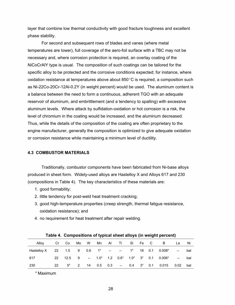
Traditionally, combustor components have been fabricated from Ni-base alloys
produced in sheet form. Widely-used alloys are Hastelloy X and Alloys 617 and 230
(compositions in Table 4). The key characteristics of these materials are:
1. good formability;
2. little tendency for post-weld heat treatment cracking;
3. good high-temperature properties (creep strength, thermal fatigue resistance,
oxidation resistance); and
4. no requirement for heat treatment after repair welding.
Table 4. Compositions of typical sheet alloys (in weight percent)
Alloy Cr Co Mo W Mn Al Ti Si Fe C B La Ni
Hastelloy X 22 1.5 9 0.6 1a -- -- 1a 18 0.1 0.008a -- bal
617 22 12.5 9 -- 1.0* 1.2 0.6a 1.0a 3a 0.1 0.006* -- bal
230 22 5a 2 14 0.5 0.3 -- 0.4 3a 0.1 0.015 0.02 bal
a Maximum
28

Approaches for maintaining metal temperatures at acceptable levels (around
950EC) involve the combination of cooling air and TBCs, or the use of ceramic tiles.
Such components have generally performed well in most types of gas turbine, but with
further increases in firing temperature likely, and more complex combustion conditions,
there has been some effort to evaluate alternative materials. Among these, both oxide
dispersion-strengthened (ODS) ferritic alloys (such as PM2000) and ceramic-matrix
composites have been considered. Some success has been achieved with SiC-SiC as
well as oxide-oxide ceramic-matrix composites,39 and engine trials have been carried out
on components manufactured from this type of material.40 ,41, -42 An example of a ceramic
composite combustor liner is illustrated in Fig. 11.
4.4 DISC ALLOYS
Since weight has normally been a less important parameter in large gas turbines
for power generation than in aero-engines, turbine discs or rotors have frequently been
manufactured from 12% Cr steels, and advanced versions of these alloys have been
introduced as strength requirements have increased. However, for the highest-
temperature conditions in the high-pressure turbines of modern gas turbines, there has
been a tendency for Ni-base alloys to replace the ferritic steels. One alloy with the
appropriate balance of properties for this application is IN706, which is a “lean” version
of alloy IN718 which is widely used in aero-engines. The compositions of the two alloys
are given in Table 5.
Fig. 11. Combustor liner manufactured from ceramiccomposite (courtesy of G. McColvin, Siemens).
29

Table 5. Compositions of typical Ni-base disc alloys (in weight percent)
Alloy Cr Co Mo Nb Al Ti Ni C Bal
IN706 16 1.0 max __ 3 0.4 max 1.75 31.5 0.06 max Fe
IN718 19 1.0 max 3 5 0.5 0.9 53 0.08 max Fe
A crucial difference between the aero and the power generation turbine is the
size of the high-pressure turbine disc, which can be up to 1.5 m in diameter in the latter
case. Consequently, successful fabrication of large forgings from Ni-base alloys
required a significant development effort [see, for instance, reports from General
Electric’s program, references],43 ,44,45,-46 which was focused on four main requirements, viz:
• freedom from segregation in large forgings;
• hot workability within the capacity of existing forging equipment;
• better machinability than IN718; and
• no increase in costs compared to IN718.
In order to achieve these objectives, the alloy composition was modified to
improve fabricability (forging, machining, and welding), while maintaining strength and
phase stability to ensure adequate toughness. As a result of careful control using
advanced melting techniques, ingots free of macro-segregation can be produced.
These are then forged and heat-treated to optimize mechanical properties. However
difficulties remain and Ni-base alloys are not yet widely used for discs in large gas
turbines. Nevertheless if higher gas temperatures are necessary for improved
efficiency, Ni-base alloys will be necessary and further development work will be
inevitable.
4.5 PREDICTION OF MATERIALS PROPERTIES BY COMPUTER MODELING
With the continuing drive to reduce costs and design cycle time in the
manufacture of power plant equipment, there has been an increase in the need for more
sophisticated materials property data. For example, in gas turbine components
(particularly blades and vanes), long-term creep data are required to support designs for
component lifetimes of 20,000 h or more. Similarly, the increased need for cyclic
capability (even in nominally base-loaded plant) has focused attention on the
requirement for fatigue data, including thermo-mechanical fatigue.
30

The test programs required to obtain such data are time-consuming and
expensive to execute. The availability of modeling techniques to supplement or to
define critical test parameters would be of enormous benefit in increasing the efficiency
of such mechanical testing programs. Modeling techniques based on thermo-chemical
approaches are widely used in the design of new alloys, and are replacing the old trial-
and-error methods which often were inefficient and time consuming. Similarly, models
based on fluid flow and on high-temperature plasticity are now used to define optimum
casting conditions for components such as turbine blades, and for optimizing forging
processes for discs and other forged products, respectively.47 The greatly-increased
computing power now widely available has been a key factor in enabling the successful
application of these modeling techniques to industrial processes, and has been
instrumental in reducing cycle time and costs.
In contrast, the application of computer-based modeling methods to the
prediction of materials properties and component performance at high temperatures has
progressed rather more slowly. Similar comments apply to the use of accelerated
testing techniques, such as those advocated by Woodford.48 However, it is likely that
the use of predictive techniques and accelerated testing will become more widespread
as confidence in the methods increases, and demand grows for more sophisticated
measures of materials performance.
A thermodynamics-based approach to the prediction of physical properties for
superalloys (such as Young’s Modulus and linear expansion), that has recently been
described,49 is based on physical principles rather than on statistical methods.
Calculated values have shown good agreement with experimental measurements for
wrought Ni-base alloys. This seemingly versatile approach has been used to calculate
TTT diagrams, as well as values of proof stress and creep rates, with encouraging
agreement with experimental measurements in each case.
Several techniques have been proposed for prediction of mechanical properties
(particularly creep) at high temperatures. Probably the most appealing method is that of
employing physically-based continuum damage mechanics (CDM), which uses
quantitative models of the deformation and fracture mechanisms in the creep regime to
develop a methodology for predicting creep in engineering alloys. A multiaxial variant
approach can be applied as a sub-routine in a finite-element program to predict the
lifetime in creep of simple components.50,51 Because it can be shown that other well-
known methods (such as the Larson-Miller parameter and the Omega parameter) can be
derived from a CDM analysis, it is evident that this methodology provides a unifying
31

framework within which apparently unrelated life-prediction methods can be rationalized.
The application of the technique in the prediction of the creep behaviour of superalloys,52
and of ferritic steels and simple power plant components,53 recently has been described.
The ultimate aim in the context of component lifetime prediction should be to
integrate the various modeling techniques, so that an optimized casting design (for
example, for a turbine blade) could then be subjected to a computer-based life prediction
analysis. If such a process were carried out on an iterative basis, one can envision a
situation where a component designed for castability would require only limited testing to
demonstrate satisfactory performance.
32

5. IMPLICATIONS FOR MATERIALS SELECTION IN GAS TURBINES BURNING SYNGAS OR HYDROGEN
5.1 PERFORMANCE TARGETS
The U.S. Department of Energy (DOE) recently has outlined performance targets
for turbines burning coal-derived gas.54 These targets are summarized in Table 6, and it
will be seen that these are nominally less demanding than the current performance of
advanced natural gas fired machines. However, the combustion of gas produced by
coal presents several additional problems not usually encountered with natural gas, and
these may have implications for performance and component design. As previously
discussed, while natural gas contributes about 2% of the overall fluid flow through the
engine, low-Btu syngas will contribute about 15-20%, and modifications must be made to
the compressor to accommodate this increased mass flow. Also, flame speed can be
increased due to the higher hydrogen content of syngas, and this can cause difficulties
in controlling combustion. Furthermore, since flame temperatures will be higher in these
conditions (Table 1), NOx control will be more difficult, so that meeting the emissions
targets could be challenging.
Table 6. U.S. DOE performance targets for gas turbinesburning coal-derived gas
Fuel Target Date Efficiency Target% (HHV) NOx, [CO2]( ppm) Cost ($/kW)
Syngas 2010
2-3% better thanFB-frame engineson syngas (45-50
overall IGCC)
< 2; [‘captureready’]
20-30%improvement
100% H2 or syngas 2012 60 Near zero; [0] <10% increaseover current plants
Oxygen/multifuel 2012 50-60 0; [100% capture] —
5.2 FUEL-RELATED CORROSION
The major areas of difficulty for materials performance in applications involving
syngas are likely to be those associated with the specific characteristics of the
combustion environment, especially the type and amount of minor species present in the
fuel, viz:
33

• the increased content of water vapor in the combustion gas, resulting not only
from the composition of the fuel gas but also from water scrubbing during clean
up;
• the sulfur level, depending on the level of clean up and the efficiency of the
process; and
• the particulate content, which is expected to be very low from clean-up scrubbing
processes, but will vary depending on the functioning of those processes with the
possibility of very high levels being attainable (albeit for relatively short times)
during plant upset conditions.
In each case, the value of these parameters is expected to be higher than for
turbines fired with natural gas, and could have an important influence on component
performance. Thus, there is a need for detailed information on the actual compositions
of the gas produced from the various gasifier technologies, with emphasis on critical
impurity levels and on particulate loading, so that the implications for component
performance can be assessed realistically. Despite the expectation that the syngas
entering the turbine will be at least as clean as demanded by the gas turbine
manufacturers’ fuel specifications, it will be important to understand the possible ranges
of impurities so that regimes of actual fuel compositions can be defined for safe
operation.
In recent studies,55,56 it has been shown that the presence of water vapor (0.1 to
0.5 atm.) could adversely affect the oxidation resistance of both chromia- and alumina-
forming alloys at temperatures between 700 and 900EC. For alumina-forming alloys, the
presence of water vapor reportedly had an adverse effect on the ability to form the
desired protective scale (α-alumina,) particularly at lower temperatures; there was some
tendency for the less-protective transient oxides to form, even at the higher
temperatures where α-alumina is expected. Interestingly, a diffusion (Ni,Pt)Al coating
performed well in moist air.55 Further, in the presence of high trace levels of sulfur in the
substrate, there was an increased tendency for the oxide to spall.
In the case of chromia-forming alloys, the formation of the volatile oxyhydroxide,
CrO2(OH)2 at temperatures as low as 600EC57 leads to accelerated oxidation and scale
spallation from the typical 18Cr-12Ni-class of austenitic steels. Steels with higher Cr+Ni
levels, and most chromia-forming Ni-base alloys experience an increased rate of loss of
Cr, which will result in reduced oxidation lifetimes. At 900EC, it was apparent that the
34
well-known tendency for Cr2O3 to evaporate as CrO3 was exacerbated in wet air, due to
the formation of CrO2(OH)2.
It is well known that alkali sulfates can cause corrosion of superalloys at high
temperatures when they are deposited as molten species.23 Such ‘hot corrosion’ has
been of less concern for turbines burning low sulfur-content natural gas, in which
oxidation is the principal degradation process, and current coatings have been
developed accordingly. With the higher sulfur levels anticipated in coal-derived fuels,
this straightforward scenario is likely to change, particularly in units on sites near the sea
where atmospheric NaCl levels will be higher. With cold syngas clean-up, it is expected
that species present as condensable vapors (and solid particles) will be essentially
eliminated before the gas enters the turbine, so that the main concern (in addition to
water vapor) will be condensable species in the combustion air, and non-condensable
species (such as sulfur-containing gases) in the fuel gas. With warm or hot gas clean-
up, the performance of the filtration and sulfur-removal systems will control not only the
amounts and types of condensable species that survive and pass into the combustor,
but also the size and concentration of solid particles derived from the gasifier. Thus, a
better definition of the allowable maximum concentrations (and size distributions) of
each contaminant for acceptable turbine life, for the range of gasifier/clean-up designs
and fuel types considered, would be prudent.
In terms of providing protection from sulfur-related corrosion, the coatings
developed to provide protection for natural gas-fired turbines typically are deficient in
chromium, the major element needed to counter sulfidation and hot corrosion attack.
The surfaces of the high pressure turbine stages that are covered by TBC The surfaces
of the high-pressure stages that are covered by TBCs likely will run at temperatures
above the condensation temperatures of salts associated with hot corrosion, so that
molten salt attack from that source is considered unlikely, except at the cooler airfoil
roots. Nevertheless, degradation from physical deposition of CMAS (mentioned earlier)
remains an issue, but this may be countered by the newer ceramics being developed for
TBCs. Corrosion protection from metallic coatings probably will be needed for the later
turbine stages, where surface temperatures will fall into the range where condensed salt
deposits can form; the compositions of the structural alloys used for these stages are
unlikely to confer inherent resistance to hot corrosion. Overall, coping with the risk of
high-temperature degradation is expected to be a major consideration in syngas-fired
gas turbines, and extensive development work on coatings systems will be required.
35

While the potential for erosion and/or deposition from the combustion of syngas
is expected to be essentially eliminated if the cold gas clean-up systems operate as
designed, the turbine manufacturers are mindful of the potential damage from the
presence of high-velocity particles. As a consequence, there is interest in approaches
(should they be needed) for guarding against surface erosion of hot gas path parts,
particularly of TBCs on airfoil leading edges; and blocking of cooling holes on blades
and vanes which could impair cooling efficiency.
5.3 MATERIALS SELECTION
From the information presented in the preceding sections of this review it will be
evident that the alloys available or currently under development for hot-gas-path
components would in principle be expected to meet the requirements in terms of
strength and long-term stability for similar applications in engines burning low-Btu gas.
Thus for components such as blades and vanes, combustors and rotors and discs,
alloys are available with performance characteristics appropriate for the syngas
application.
However an important limitation lies in the ability of these materials to
demonstrate long-term durability in environments that may be more corrosive due to
increased sulfur levels, and where the presence of particulates could cause loss due to
erosion of coatings, which are critical to component longevity. Alloys and coatings
currently used in engines burning natural gas have been designed to resist oxidation in
relatively clean environments. Since sulfur levels will undoubtedly be higher in syngas
combustion environments, the need for a high-strength single-crystal alloy with good
resistance to sulfidation attack when coatings are breached will almost certainly emerge.
Equally, the current generation of oxidation-resistant coatings may have to be
augmented by coatings with greater sulfidation resistance, which typically is equated
with higher levels of chromium. The development of alloys and coatings with the
capability of operating at high temperatures while maintaining good compatibility with the
substrate alloys in sulfidizing environments will represent a considerable challenge to
the materials community.
Furthermore, if engines burning syngas are required to operate at efficiencies
comparable to those of turbines burning natural gas, a significant increase in firing
temperatures will be necessary and, since it is likely that materials for critical
36
components will be limited to superalloys for the foreseeable future, novel component
designs and improved TBCs will be required to cope with the more demanding
conditions. An example of a design for a component with a higher-temperature
capability was reported recently, and is being developed in a German national
program.58 The so-called core and skin design has been proposed before, and has the
advantage that cooling channels can be located very close to the component surface,
thereby maximizing the impact of the cooling air. This work is at an early stage, but may
indicate the type of approach required for these very demanding conditions. Similarly,
disc alloys with enhanced performance will be required, since the martensitic steels will
not withstand the projected higher temperatures. Consequently, further development of
suitable Ni-base alloys will be necessary in order to establish fabrication methods for
large, high-strength discs with microstructures that give high defect tolerance and good
structural integrity. For combustors and burners, wider application of ceramic and ODS
materials may be necessary.
The oxygen/multifuel target indicated in Table 6 is being addressed in a program
that uses combustion technology developed by Clean Energy Systems and turbine
technology from Siemens Power Generation.59 The combustion conditions discussed
concerning the development of the oxygen/syngas/hydrogen combustor60 raise some
potentially challenging issues for materials selection. The fully-developed combustion
process is envisioned to deliver steam-CO2 mixtures at temperatures and pressures
ranging up to 1760EC and 22 MPa into the turbine, which will require either a major
revision of the cooling technology applied to the first stages of vanes and blades, or
possibly the use of ceramics. A further issue is that there is very little experience of the
compatibility of available high-temperature materials with steam and steam-CO2
mixtures at such extreme conditions.
Earlier studies in support of the Japanese-sponsored World Energy Network
Program (WE-NET),61 which involved combustion of hydrogen and oxygen in a gas
turbine at temperatures up to 1700EC,62 highlighted the need for advanced cooling
concepts, especially for the combustor and transition ducting, and for information on the
operability of the combustor. The major materials issues identified were associated with
the durability of Ni-based superalloys with appropriate corrosion-resistant coatings and
TBCs; concerns ranged from hydrogen embrittlement, stress corrosion cracking, and
creep rupture to oxidation and corrosion deposits.
37

Depending on the final choice of materials and the exact nature of the
environmental conditions, there may be a requirement for improvements in the property
database, particularly for long-term creep and fatigue data. In this connection, it may
be possible to obtain useful support from the current projects supported by the U.S.
Department of Energy on, for instance, materials for applications in ultra-supercritical
steam where work on selected Ni-base superalloys includes the generation of long-term
data on properties at high temperatures.63 Also, the results of work at the Oak Ridge
National Laboratory to develop a broadly based compilation of materials property data64
using the Granta System65 will provide a valuable resource.
38
6. SUMMARY OF MATERIALS NEEDS
For all fuel scenarios considered, it is apparent that increased turbine operating
temperatures will be required, so that materials with higher temperature capabilities are
a necessity. A distinction can be made between the materials needs for syngas-based
fuels and hydrogen. For syngas combustion, consideration must be given to the
possibility that the combustion products may contain levels of contaminants (from the
coal) capable of providing accelerated surface degradation through deposition, erosion,
or corrosion. The increased levels of water vapor from syngas also are thought to be
capable of modifying the characteristics of the normally-protective oxide films formed on
alloys and coatings. For hydrogen fuel scenarios, the additional processing steps
experienced by the fuel make it likely that the only source of such contaminants will
be the combustion air (if used), so that the major environmental concerns will be
high-temperature oxidation, particularly water vapor-accelerated oxidation from the
higher levels of water vapor-accelerated oxidation from the higher levels of water vapor
in the combustion gas, and possibly hydrogen embrittlement from steam. In addition,
the combustion temperatures for hydrogen-based fuels are expected to be higher than
for syngas, so that materials options that maximize temperature capability, and
component designs that maximize cooling will be paramount.
6.1 NEEDS RESULTING FROM THE PURSUIT OF HIGHER FIRING TEMPERATURES
The differences in CV and combustion characteristics among natural gas,
syngas, and hydrogen have significant implications for the ability to maintain power
output, emissions levels, and component cooling. As indicated earlier, there is concern
that these issues, as they affect gas temperatures and flow rates, will require changes or
compromises in the detailed design of the turbine in order to provide sufficient control of
the temperatures of critical components to ensure their reliability. There is little margin
for increasing the operating temperature of the superalloys available for use in large
turbines, so that it appears essential that the temperatures expected to be experienced
by critical hot gas path components be carefully defined for the range of combustion
conditions likely in any given turbine operating scenario. This requirement highlights the
39

need for measurement and/or modeling developments to provide confidence in setting
operating parameters and limits in the context of materials performance.
There are several pressing issues. One is the design of combustor systems
capable of coping with the flame characteristics of the range of fuels of interest. The
need to control the combustion process to avoid flame detachment from the burner
nozzles to prevent overheating, and of avoiding flashback while maintaining the desired
low levels of NOx, ideally requires combustion zones of specific dimensions and/or
shape for each fuel. This situation makes the concept of dual- or multi-fuel capability
difficult to achieve in a single combustor design. Combustor liner materials typically are
highly-cooled alloys with, in some cases, little margin for temperature increase, so that
materials that require less cooling would provide improved operating flexibility, and are a
continuing need.
For the airfoils, the primary need is to reduce the initial costs and to simplify the
manufacturing procedures for SC components. It is considered likely that the alloys that
will be preferred will have improved castability and production yield, which are likely to
be achieved at the expense of limitations in high-temperature capabilities. Some
progress already has been made in this regard. Nevertheless, it appears that the
compromises necessary to achieve an acceptable cost reduction in SC components
available for land-based turbines will lead to alloys that have maximum metal
temperature capabilities that are at best similar to those of the current 2nd generation SC
alloys. Their actual maximum use temperatures will be limited by engine size, loading
per stage, and duty cycle, and by innovations in design. Thus, the available mechanical
property data for, for instance, alloy CMSX-4 should provide a good guide for suggesting
the maximum permissible metal temperature for superalloys for land-based turbines and,
since this will be significantly lower than the rotor inlet temperatures commensurate with
the goals listed in Table 6, there will be a need to carefully control turbine operation to
ensure that these temperatures are not exceeded.
In general, since it appears that the development of Ni-based superalloys for
land-based turbines has reached the point where further gains in temperature capability
are likely to be small, and since on the basis of present evidence no successor material
(such as ceramics or refractory-based alloys) will emerge in the near future, further
increases in firing temperatures will require an overall approach combining optimization
of alloy compositions and cooling technologies (including thin-walled castings and
TBCs). This is particularly necessary where combustion temperatures may be
40

appreciably higher than in current experience (as appears to be the case for hydrogen-
oxygen combustion). In particular, since coatings likely will comprise a significant
fraction of the thickness of the vane/blade wall, greater attention will need to be devoted
to improving the compatibility of alloys and coatings, as loss of useful wall section
through corrosion or interaction between coating and superalloy will be very detrimental.
For rotors and discs, materials currently in use in gas turbines burning natural
gas are operated at the limits of their high-temperature strength, and will be inadequate
should higher temperatures be necessary for improved efficiency with syngas/hydrogen
firing. In this case, greater use of nickel-chromium alloys will be inevitable and,
depending on the detailed characteristics of the engine design, efforts to further improve
the manufacturing processes and reduce costs will be necessary. In addition, there is a
requirement for long-term data on mechanical properties (thermo–mechanical fatigue in
particular) to provide a basis for increased component lifetime and lifetime modeling.
Improved computational modeling techniques for life prediction of critical components
are required, and will contribute to the overall aim of enhanced component durability.
Overall, there are materials available or under development that are capable of
the performance and durability for the nominal conditions of syngas applications, but
only provided that the relevant components are cooled so that they do not exceed
prescribed temperatures.
6.2 EVOLVING NEEDS FROM CONSIDERATION OF HYDROGEN AS GAS TURBINE FUEL
The scenarios for the use of hydrogen in IGCC/GTCC applications were still
being evolved as this report was prepared, so that any conclusions concerning specific
materials needs probably are premature. Nevertheless, the following comments are
offered. The implications for materials selection and use from scenarios for augmenting
syngas with hydrogen, and the issues from using air-oxygen mixtures for combustion are
probably very similar to those discussed above for syngas. The major differences arise
for the case where hydrogen and oxygen are the sole/major reactants, in cycles aimed
at minimizing emissions. Such cycles typically involve gas temperatures at or above the
extreme upper limit of those considered (and certainly above the range for which there is
experience) in conventionally-fueled land-based turbines. Because testing in such
environments will be difficult and expensive, modeling approaches that are capable of
41

generating data on the local temperatures and heat transfer conditions experienced by
the hot gas-path components that are associated with the various combustion scenarios
are probably the only means of providing vital guidance for materials selection and
cooling requirements, and will be extremely valuable. Since increases in firing
temperature probably cannot be accommodated by the incremental improvements in
current materials discussed above, new approaches to cooling of critical components
probably will be needed, or a commitment made to combinations of radical design and
materials applications, and to pioneering of their insertion into critical areas.
The additional processing required to convert syngas to hydrogen and to extract
oxygen from air is considered to effectively remove all impurities typically implicated in
hot gas path corrosion, so that the main environmental concerns are with the corrosive
effects of high-temperature and high-pressure steam (including hydrogen embrittlement).
This also is an area where data are scarce, so that a commitment to some relatively
fundamental materials compatibility research will be necessary.
6.3 NEEDS RESULTING FROM CONCERNS ABOUT FUEL PURITY
An additional important difference compared to prior experience with natural gas-
fired GTCC practice is the range and level of potential impurities possible in syngas, and
the implications for alloy/coating durability. Even though it is expected that the fuel
supplied to the turbine will be within current fuel specifications, there is a need for better
understanding and quantification of the potential threat to component durability from
(1) the higher water vapor levels, and (2) the different impurities possible in gasifier
streams, which can vary significantly among gasifier types and gas clean-up
configurations. A definitive evaluation of the actual gas compositions delivered to the
turbine, together with understanding of the disposition of the species resulting from
combustion, is considered essential for assessing potential implications for the range of
gasification processes, clean-up options, and turbine designs of interest.
Depending on the likelihood of the presence in the combustion gas of sufficient
quantities of species that have the potential to contribute to problems of D-E-C, coatings
with increased resistance to sulfur-related oxidation-sulfidation or hot corrosion may be
needed. These coatings will require significantly different compositions than current
coatings, which have been optimized for resistance to high-temperature (sulfur-free)
oxidation. An issue here is the need to ensure that the mechanical properties of the
42

coatings do not degrade the resistance of the airfoils to, for instance, thermal-
mechanical fatigue. In addition, since these turbines are expected to operate at very
high temperatures for long times, it is necessary to ensure compatibility between
coatings and superalloy substrates, especially in terms of reducing the effects of
interdiffusion on the stability of the alloy microstructure, and the life of the coating. A
well-known issue is that the properties of sulfidation resistance, oxidation resistance,
and compatibility with SC alloy compositions (in terms of chemical interactions) usually
are not readily combined in a single coating composition. Thus, there may be
opportunities for developing hybrid coating designs capable of combining some of these
functions.
There may be potential for further development of polycrystalline, DS materials,
since there is probably more scope for increasing their chromium content than for SC
compositions. It is likely that a key requirement of components for which DS alloys are
candidates will be for alloys with greater corrosion resistance, while maintaining high-
temperature strength, and this will be a challenging task. Also, as was the case for
rotors and discs, long-term data on both creep and fatigue properties, and improvements
in computational modeling methods, will contribute to better durability of these critical
components.
6.4 OVERALL SUMMARY OF MATERIALS NEEDS
The materials issues resulting from the need for advanced gas turbines to
operate with fuels other than clean, natural gas are summarized in Table 7, which
attempts to provide a simple ranking of the level of effort necessary to provide the
needed materials. In the Table, the level of effort required has been given a subjective
numerical rating from 1 to 3, where ‘1’ suggests that considerable research and
development will be needed, while a ranking of ‘3’ indicates that most of the capability
required is already available. Distinction is made between the materials needs for
syngas and hydrogen, on the assumption that the combustion of hydrogen will involve
higher temperatures and certainly higher levels of water vapor.
Finally, there exists a major need to demonstrate that available materials can be
made into actual components that work as intended, and to obtain property data for
design purposes and service life prediction. While demonstration of the workability of a
syngas- or hydrogen-fired advanced gas turbine is an expensive undertaking, even at
43

component-demonstration level, it represents a necessary milestone that must be
reached in order for the utility industry to accept this technology. It is therefore
recommended that a demonstration phase (at least for materials and key components) is
indicated as a common culmination point for all materials and components development
programs.
Table 7. Ranking of overall materials needs
ComponentRating
Major issuesSyngas H2
Combustors Materials 2 1 Cooling; TBCs; lifetime
Manufacturing 2 1 Design for multifuel use
Vanes/blades Materials 3 1 Higher-T capability; better corrosion
resistance; lower cost
Manufacturing 2 1 Improved yield; lower cost
Bond coatings Materials 1 1 Durability/compatibility with superalloy
Manufacturing 2 1 Cost; process control
Ceramic
thermal barrier
layers
Materials 1 1 Reduced thermal conductivity; longer
lifetime; predictability
Manufacturing 2 1 Cost; reproducibiity
Rotors/discs Materials 3 2 Large Ni-base forgings; design data;
weldability
Manufacturing 1 1 Melting, forging, fabrication (welding?)
44
7. CONCLUSIONS
• The stated performance goals for turbines intended for operation on syngas and
hydrogen fuels will require firing temperatures at least as high as those achieved by
state-of-the-art turbines designed for natural gas.
• For syngas service, there are complicating factors due to differences in CV and
combustion characteristics compared to natural gas, and these have significant
implications for the ability to maintain power output, emissions levels, and
component cooling. The potential threat of environmental degradation from fuel-
derived impurities in syngas introduces further differences in materials performance
requirements compared to natural gas firing.
• A consequence of the use of hydrogen fuel will be the need for higher firing
temperatures, together with the threat of high-temperature oxidation and hydrogen
embrittlement in steam under conditions for which there is little prior experience.
• For components, such as blades and vanes, exposed to the highest temperatures in
large gas turbines for power generation applications, several SC alloys are available
with a well-established record of performance (in natural gas service).
• Recent advances in understanding the factors controlling defect formation during
the production of SC castings have resulted in alloys optimized for tolerance of
defects and simplified post-casting heat treatments, and consequently lower costs.
• Improvements in DS alloys (with columnar grain structures) have provided some
options for enhanced performance for components operating at somewhat lower
temperatures.
• Developments in coating systems (bond coatings and thermal barriers) have
contributed to component durability in natural gas service, although reliability needs
improvement. However, such coatings were developed for resistance to high-
temperature oxidation, and may not provide sufficient protection against potential
sulfur-related corrosion scenarios from impurities in syngas.
• Some progress has been claimed in the development of ceramic composites for
combustor liners.
• Ni-base alloys have been developed that are suitable for replacing ferritic steels for
large-diameter discs for higher-temperature applications in high-pressure turbines,
but forging processes are problematical.
45

• Because the proposed applications will involve the operation of high-temperature
materials near their performance limits, it will be critical to possess accurate
knowledge of the conditions actually experienced in service. Acquisition of such
knowledge probably will require a combination of analytical and sensing techniques.
• The use of analytical modeling appears to be essential for the generation of
information to guide materials selection and cooling requirements/component
design for the hydrogen combustion scenarios, for which materials compatibility
information is sparse, and in which testing will be difficult.
• Long-term data on the creep fatigue and stress relaxation behavior of critical
materials will be required to provide an improved basis for design of hot gas path
parts and the related materials selection.
46

8. ACKNOWLEDGMENTS
This work was funded by the Office of Coal and Power R&D, Office of Fossil
Energy, U.S. Department of Energy, under contract DE-AC05-00OR22725 with
UT-Battelle, LLC, with technical management by the National Energy Technology
Laboratory (NETL), Morgantown, West Virginia. Discussions with the NETL staff,
especially with Richard Dennis and George Richards, are gratefully acknowledged. We
would also like to acknowledge helpful comments by staff members of General Electric,
Greenville, South Carolina; Siemens Power Generation, Incorporated, Orlando, Florida;
Alstom Power, Baden, Switzerland (especially Peter Holmes); and from Fred Starr
(currently at the European Joint Research Centre, Petten, The Netherlands), and by
colleagues Bruce Pint, Peter Tortorelli, and Dane Wilson at ORNL. We are grateful to
Gordon McColvin, of Siemens for the provision of figures.
47

1. P. D. Holmes, Gas Turbine Development Strategy, www.came-gt.com.
2. W. P. Parks, Jr., P. Hoffman, M. A. Karnitz, and I. G. Wright,“ The AdvancedTurbine Systems Program in the U.S.A.,” pp. 1789-1805 in Materials forAdvanced Power Engineering 1998, J. Lecomte-Beckers, F. Schubert, andP. J. Ennis, Eds., Forschungszentrum Julich (1998).
3. S. Nagamatsu, K. Mizuhara, Y. Matsuta, A. Iwanaga, and S. Ishiwata,“Current Status of Industrial and Automotive Ceramic Gas Turbine R&D inJapan,” Paper No. 91-GT-101, presented at the ASME Intl. Gas Turbine &Aeroengine Congress and Exposition, Orlando, Florida (1991).
4. High-Temperature Materials 21 Project, Conducted by NIMS, Japan, 1999 to2008.
5. Programs under the European Cooperation in the Field of Scientific andTechnical Research (COST) framework; COST 501 Focused on AdvancedMaterials for Power Engineering Components for High-Efficiency, Low-Emissions Systems. COST Website: http://cost.cordis.lu.
6. Figure from Siemens Power Generation,www.powergeneration.siemens.com.
7. J. Natarajan, S. Natarajan, S. Nandula, T. Lieuwen, and J. Seitzman,“Lamina Flame Speeds of Synthetic Coal Gas Mixtures,” ASME paper No.GT-2005-68917, presented at the ASME Turbo Expo 2005: Power for Land,Sea, and Air, Reno-Tahoe, Nevada (2005).
8. Q. Zhang, D.R. Noble, and T. Lieuwen, “Blowout Measurements in aSyngas-Fired Turbine Combustor,” presented at the 22nd Ann. Intl. PittsburghCoal Conference, Pittsburgh, Pennsylvania (2005).
9. www.EngineeringToolbox.com.
10. GREET Transportation Fuel Cycle Analysis Model (v.1.7 beta), ANL (2006);www.transportation.anl.gov/software/GREET/index.html.
11. H.I.H. Saravanamuttoo, C.F.C. Rogers, and H. Cohen, Gas Turbine Theory,5th Edtn., FT-Prentice Hall (2001).
12. See, for instance, “Specification for Fuel Gases for Combustion in Heavy-Duty Gas Turbines,” General Electric Specification GEI 41040G, revisedJanuary 2002.
13. See, for instance, M. Valenti, “Reaching for 60 Percent,” MechanicalEngineering, 124 (4), 35-39 (2002).
9. REFERENCES
49
14. F. C. Holden, H. J. Cialone, M. P. Landow, I. G. Wright, and C. M. Jackson,Combustion Turbine Materials Problems, EPRI AP-4475 (RP 2382-2), March1986.
15. T. B. Gibbons, pp.123-135 in Processing and Design Issues in High-Temperature Materials, N. S. Stoloff and R. H. Jones, Eds., TMS,Warrendale, PA (1996).
16. G. L. Erickson and K. Harris, “DS and SX Superalloys for Industrial GasTurbines,” pp. 1055-1074 in Materials for Advanced Power Engineering1994, D. Coutsouradis, J. H. Davidson, J. Ewald, P. Greenwood, T. Khan,M. Malik, D. B. Meadowcroft, V. Regis, R. B. Scarlin, F. Schubert, andD. V. Thornton, Eds., Kluwer Academic Publishers (1994).
17. Y. Koizumi, et al., Superalloys 2004, pp. 35-43, K. A. Green, T. M. Pollock,H. Harada, T. E. Howson, R. C. Reed, J. J. Schirra and W. S. Walston, Eds.TMS, Warrendale, PA, 2004.
18. K. Harris and J. B. Wahl, ibid. pp. 45-52.
19. R. Hashizume et al., ibid. pp 53-62.
20. R. Hashizume, A. Yoshinari, T. Kiyono, Y. Murata, and M. Morinaga,“Development of Ni-Based Single Crystal Superalloys for Power-GenerationGas Turbine Blades,” pp. 273-286 in Materials for Advanced PowerEngineering 2006, J. Lecomte-Beckers, M. Carton, F. Schubert, andP. J. Ennis, Eds., Schriften des Forschungszentrums Jülich ReiheEnergietechnik/Energy Technology, 53, part 1 (2006).
21. A. Sato, A-C Yeh, T. Kobayashi, T. Yokokawa, H. Harada, T. Murakumo,and J. Zhang, “A 5th Generation Ni-based Single Crystal Superalloy withSuperior Elevated Temperature Properties,” ibid., pp. 287-298.
22. M. Lamm, A. Volek, O. Luesebrink, and R. F. Singer, “Influence ofSolidification Conditions on Homogenization Heat Treatment and MechanicalProperties in Single Crystal Nickel-Base Superalloys,” ibid., pp. 334-344.
23. See, for instance, Proc. Workshop on Materials and Practices to ImproveResistance to Fuel-Derived Environmental Damage in Land- and Sea-BasedTurbines, EPRI report No. 1009173, Oct. 2003.
24. R. Burgel et al., Superalloys 2004, pp. 25-34. K.A. Green, T. M. Pollock,H. Harada, T. E. Howson, R. C. Reed, J. J. Schirra and W. S. Walston, Eds.TMS. Warrendale, PA, 2004.
25. M. Sato et al, 2nd Int. Symp. On High Temperature Materials, NIMS, Japan,pp. 28-29, 2001.
50
26. W. S. Walston, Superalloys 2004, pp 579-588, K. A. Green, T. M. Pollock,H. Harada, T. E. Howson, R. C. Reed, J. J. Schirra, and W. S. Walston, Eds,TMS Warrendale, PA, 2004.
27. J. A. Haynes, M. J. Lance, B. A. Pint, and I. G. Wright, “Characterization ofCommercial EB-PVD TBC Systems with CVD(Ni, Pt) Al Bond Coatings,”Surface Coatings Technology, 146-147, 140-146 (2001).
28. See, for instance: A. G. Evans, J. W. Hutchinson, and M. Y. He, Acta Met.,47, 1513-1522 (1999).
29. P. Deb, D. H. Boone, and T. F. Manley, J. Vac. Sci. Technol. A., 5 (6), 3366(1987).
30. See, for instance: M. Gell, K. Vaidyanathan, B. Barber, J. Cheng, andE. Jordan, Metal. Mater. Trans., 30A, 427-435 (1999).
31. J. G. Smeggil, A. W. Funkenbusch, and N. S. Bornstein, Met. Trans., 17A,923 (1986).
32. J. L. Smialek and B. K. Tubbs, Met. Trans., 26A, 427-435 (1995).
33. B. A. Pint, I. G. Wright, W. Y. Lee, Y. Zhang, K. Prüssner, and K. B.Alexander, Mat. Sci & Eng., A245, 201-211 (1998).
34. P. Morell, D. S. Rickerby, pp. 20-21 to 20-29 in Proc. AGARD-R-823 (1998).
35. C. G. Levy et al., Coatings for Advanced Gas Turbines, Summary ofResearch Needs and Proposed Actions, prepared for DOE, FETC.
36. M. P. Borom, C. A. Johnson, and A. L. Peluso, “Role of EnvironmentalDeposits in Spallation of Thermal Barrier Coatings on Aero Engine andLand-Based Gas Turbine Hardware,” Paper No. 96-GT-285, presented atthe ASME Turbo Expo ‘96, June 10-13, 1996, Birmingham, England.
37. M. F. Trubelja, D. M. Nissley, N. S. Bornstein, and J.T.D. Marcin, “Pratt &Whitney Thermal Barrier Coating Development,” in Proceedings, AdvancedTurbine Systems Annual Program Review Meeting, DOE/FETC-98/1057,DE98002004, CONF-971053 (Report No. 5.9) (1997).
38. See, for instance, M. J. Maloney U.S. Patent No. 6,284,323, 2001.
39. J. Kimmel, J. Price, K. L. More, P. F. Tortorelli, E. Sun, and G. Linsey, “TheEvaluation of CFCC Liners after Field Testing in a Gas Turbine-IV,” paperNo. GT2003-38920 in Proc. ASME Turbo Expo 2003: Power for Land, Seaand Air, Atlanta, Georgia, USA (2003).
40. A. Szweda, S. Butner, J. Ruffoni, C. Bacalski, J. Layne, J. Morrison,G. Merrill, M. van Roode, A. Fahme, D. Leroux, and N. Miriyala,"Development and Evaluation of Hybrid Oxide/Oxide Ceramic Matrix
51
Composite Combustor Liners," paper No. GT2005-68496 in Proc. ASMETurbo Expo 2005: Power for Land, Sea and Air, Reno/Tahoe, Nevada, USA(2005).
41. J. A. DiCarlo and M. van Roode, “Ceramic Composite Development for GasTurbine Engine Hot Section Components,” paper No. GT2006-90151 inProc. ASME Turbo Expo 2006: Power for Land, Sea and Air, Barcelona,Spain (2006).
42. F. Carchedi, pp. 3-23 in Engineering Issues in Turbine Machinery PowerPlant and Renewables 2003, A. Strang, R.D. Conroy, W.M. Banks,M. Blackler, J. Leggett, G.M. McColvin, S. Simpson, M. Smith, F. Starr andR. W. Vanstone, Eds, IOM, London 2003.
43. P. W. Schilke, J. J. Pepe, and R. C. Schwant, “Alloy 706 Metallurgy andTurbine Wheel Application,” pp. 1-12, in Superalloys 718, 625, 706, andVarious Derivatives, E. A. Loria, Ed., TMS Publications (1994).
44. R. C. Schwant, S. V. Thamboo, A. F. Anderson, C. B. Adasczik, B. J. Bond,L. A. Jackman, and J. F. Uginet, “Large 718 Forgings for Land BasedTurbines,” pp. 141-152 in Superalloys 718, 625, 706, and VariousDerivatives, E. A. Loria, Ed., TMS Publications (1997).
45. P. W. Schilke, and R. C. Schwant, “Alloy 706 Use, Process Optimization,and Future Directions for GE Gas Turbine Rotor Materials,” pp. 25-34 inSuperalloys 718, 625, 706, and Various Derivatives, E. A. Loria, Ed., TMSPublications (2001).
46. R. C. Schwant, S. V. Thamboo, L. Yang, and M. Morra, “Extending the Sizeof Alloy 718 Rotating Components,” pp. 15-24 in Superalloys 718, 625, 706,and Various Derivatives, E. A. Loria, Ed., TMS Publications (2005).
47. See for instance, Casting Simulation Solutions: PROCAST/QUICKCAST,ES1 North America, Bloomfield Hills, Michigan (2007).
48. D. A. Woodford, “Stress Relaxation Testing,” pp. 398-404 in MechanicalTesting and Evaluation, Vol. 8, ASM Handbook (2000).
49. N. Saunders, Z. Guo, X. Li, A. P. Miodownik, and J-Ph. Schille, “Modelingthe Materials Properties and Behavior of Ni-Based Superalloys,” Superalloys2004, pp. 849-858, K. A. Green, T. M. Pollock, H. Harada, T. G. Howson,R. C. Reed, J. J. Schirra and W. S. Walston, Eds., TMS Warrendale, PA(2004).
50. A. M. Othman, B. F. Dyson, D. R. Hayhurst, and J. Lin, “Continuum DamageMechanics Modeling of Circumferentially-Notched Tension Bars UndergoingTertiary Creep with Physically-Based Constitutive-Equations,” Acta Metall.Mater., 42, 597-611 (1994).
51. J. Yang et al., ASME J. Pressure Vessel Technology, 126, 369-375 (2004).
52
52. H. Basoalto, S. K. Sondhi, B. F. Dyson, and M.McLean, “A GenericMicrostructure-Explicit Model of Creep in Ni-Base Superalloys,” pp. 897-906in Superalloys 2004, K. A. Green, T. M. Pollock, H. Harada, T. G. Howson,R. C. Reed, J. J. Schirra and W. S. Walston, Eds., TMS Warrendale, PA(2004).
53. B. F. Dyson, ASME, J. Pressure Vessel Technology, 122, 2000,pp. 281-296.
54. “Enabling Turbine Technologies for High-Hydrogen Fuels,” U.S. Departmentof Energy Solicitation No. DE-PS26-05NT42380, issued March 31, 2005.
55. K. Onal, M. C. Maris-Sida, G. H. Meier, and F. S. Pettit, “The Effects ofWater Vapor on the Oxidation of Ni-Base Superalloys and Coatings atTemperatures from 700 to 1100°C,” pp. 607-615 in Superalloys 2004, K. A.Green, T. M. Pollock, H. Harada, T. G. Howson, R. C. Reed, J. J. Schirraand W. S. Walston, Eds., TMS Warrendale, PA (2004).
56. B. A. Pint, J. A. Haynes, Y. Zhang, K. L. More and I. G. Wright, “The Effect ofWater Vapor on the Oxidation Behavior of Ni-Pt-Al Coatings and Alloys,”Surface and Coatings Technology, 201, 3852-3856 (2006).
57. E. J. Opila, “Volatility of Common Protective Oxides in High-TemperatureWater Vapor: Current Understanding and Unanswered Questions,”Materials Science Forum, 461-464, 765-773 (2004).
58. D. Bohn, Modern Power Systems, September 2006, pp. 25-27.
59. “Enabling Turbine Technologies for Hydrogen Fuels,” DOE-Fossil EnergyTechline, Sept. 8, 2005.
60. See, for instance, R. Anderson, H. Brandt, S. Doyle, K. Pronske F. Viteri,“Power Generation with 100% Carbon Capture and Sequestration,”Presented at the 2nd Annual Conference on Carbon Sequestration,Alexandria, VA, May 5-8, 2003.
61. C. Mitsugi, A. Harumi, and F. Kenzo, “Japanese Hydrogen Program,” Int’l. J.of Hydrogen Energy, 23 (3), 159-165 (1998).
62. R. L. Bannister, R. A. Newby, and W. C. Yang, “Development of a Hydrogen-Fueled Combustion Turbine Cycle for Power Generation,” J. Eng. for GasTurbines and Power, 120, 276-283 (1998).
63. R. Viswananthan, J. F. Henry, J. Tanzosh, G. Stanko, J. P. Shingledecker,B. Vitalis, and R. Purgert, “U.S. Program on Materials Technology for Ultra-Supercritical Coal Power Plants,” Journal of Materials Engineering andPerformance, 14 (3), 281-292 (2005).
64. P.J. Maziasz, I. G. Wright, and V. Viswanathan, “Advanced Materials forUSC Steam Turbines,” presented at the Clean Coal Conference, Clearwater,FL (2006).
53

65. Granta MI Software, Granta Design, Ltd., Cambridge, England.
54

ORNL/TM-2009/137
INTERNAL DISTRIBUTION
1. S. J. Pawel
2. B. A. Pint
3. F. C. Stooksbury
4. P. F. Tortorelli
5. D. F. Wilson
6–25. I. G. Wright
26. S. J. Zinkle
27. Central Research Library
28. ORNL Laboratory Records–RC
EXTERNAL DISTRIBUTION
29. C. T. Alsup, DOE National Energy Technology Laboratory, 3610 Collins Ferry
Road, P.O. Box 880, Morgantown, WV 26507-0880
30. M. A. Alvin, DOE National Energy Technology Laboratory, 626 Cochrans Mill
Road, P.O. Box 10940, Pittsburgh, PA 15236-0940
31. B. Bordenet, Alstom (Switzerland) Ltd., Dept. TGTM, Brown Boveri Strasse 7,
5401 Baden, Switzerland
32. R.A. Dennis, DOE National Energy Technology Laboratory, 3610 Collins Ferry
Road, P.O. Box 880, Morgantown, WV 26507-0880
33. R.B. Dooley, Structural Integrity Associates, Inc., 2616 Chelsea Drive,
Charlotte, NC 28209
34. D. Gandy, EPRI, 1300 West W.T. Harris Blvd, Charlotte, NC 28262
36–41. T.B. Gibbons, Consultant, 5005 Nicholas Creek Circle, Wilmington, NC 28409
42. D. Helmick, General Electric Energy, Materials and Processes Engineering, PO
Box 648, Greenville, SC 29602
43. A. James, Siemens Power Generation Inc., Superalloy Technology (USA), 4400
Alafaya Trail, MC Q3-031, Orlando, FL 32826-2399
44. A. A. Kulkani, Siemens Power Generation Inc., Materials Engineering, 4400
Alafaya Trail, MC Q3-031, Orlando, FL 32826-2399
55

45. G.M. McColvin, Siemens Industrial Turbomachinery, Ruston House, P.O. Box 1,
Waterside South, Lincoln LN5 7FD, England
46. A. Manivannan, DOE National Energy Technology Laboratory, 3610 Collins
Ferry Road, P.O. Box 880, Morgantown, WV 26507-0880
47. P. A. Rawls, DOE National Energy Technology Laboratory (NETL-PGH),
Gasification and Fuels Division, P.O. Box 10940, 626 Cochrans Mill Road,
Pittsburgh, PA 15236-0940
48. Robert R. Romanosky, Jr., DOE National Energy Technology Laboratory,
(NETL-MGN), Office of Coal and Power Research and Development, P.O. Box
880, 3610 Collins Ferry Road, Morgantown, WV 26507-0880
49. John Shingledecker, Senior Project Manager, Fossil Materials & Repair
Program (P87), EPRI, 1300 West W. T. Harris Blvd., Charlotte, NC 28262
50. N. J. Simms, Cranfield University, School of Industrial and Manufacturing
Science, Power Generation Technology Centre, Cranfield MK43 0AL, Beds.,
England
51. F. Starr, Visiting Scientist, JRC-European Commission, P.O. Box 2, 1755 ZG
Petten, The Netherlands
52. J. Stringer, Izambard, 221 Hudson Street, Redwood City, CA 94062-1921
53. R. Viswanathan, EPRI, 3412 Hillview Ave., Palo Alto, CA 94303
54. R. A. Wenglarz, SCIES, 386-2 College Avenue, Clemson, SC 29634
56