Embed Size (px)
Citation preview
A re-think of the mercury removalproblem for LNG plantsBy Peter J H CarnellVince A Row & Rachel McKenna
JM_257 Puraspec LNG brochure v4 13/4/07 14:47 Page 2
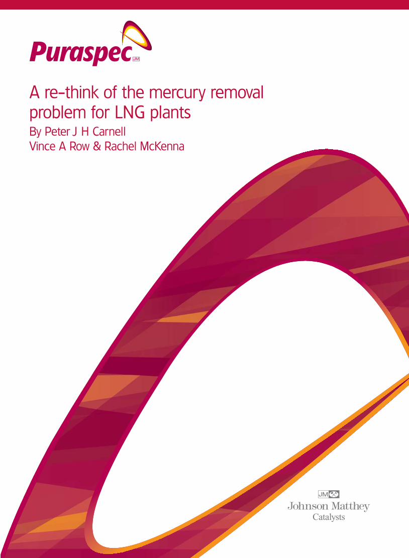
Information contained in this publication or as otherwise supplied to Users is believed to be accurate and correct at time ofgoing to press, and is given in good faith, but it is for the User to satisfy itself of the suitability of the product for its own particularpurpose. Johnson Matthey plc (JM) gives no warranty as to the fitness of the Product for any particular purpose and any impliedwarranty or condition (statutory or otherwise) is excluded except to the extend that exclusion is prevented by law. JM accepts noliability for loss or damage (other than that arising from death or personal injury caused by JM’s negligence or by a defectiveProduct, if proved), resulting from reliance on this information. Nothing here in should be considered to provide freedom tooperate under any Patent.
JM_257 Puraspec LNG brochure v4 13/4/07 14:47 Page 3
AbstractFollowing the mercury induced catastrophic failure of a heat
exchanger at Skikda in 1957, the LNG industry had to move quickly
to install mercury removal units (MRUs) prior to liquefaction. At that
time, the choice of absorbent was limited and MRUs had to be
installed at the final stage of purification immediately prior to the
cold box. This was not the best arrangement. By not treating the
raw gas, mercury was left in co-produced NGLs and might also be
released to the atmosphere during processing. Commissioning of
new beds lengthened start up and the choice of location added to
compression costs.
The arrival of new high activity mercury absorbents has allowed the
re-thinking of the purification process. The MRU can now be located
at the front of the plant to treat the raw gas thus avoiding mercury
in NGLs or in emissions. The high activity allows smaller beds to be
used and the use of radial flow reactors allows significant savings in
compression costs over the traditional axial flow design. The new
absorbents can be recycled through an audited disposal route.
This paper draws on data from actual operating MRUs to suggest
how the design of LNG plants could be improved.
JM_257 Puraspec LNG brochure v4 13/4/07 14:47 Page 4
IntroductionAlmost all hydrocarbons contain mercury. In the case of natural gas
and natural gas liquids it is likely to be present as elemental mercury.
In the case of crude oil it may also be present as organo-metallic
and ionic mercury.
The concentration of mercury in natural gas varies widely from 450
to 5000 µg/Nm3 in some fields in North Germany [1] to less than
0.01µg/Nm3 in some parts of the US and Africa. Reported levels of
mercury found in some well known gas fields are given in Table 1
Mercury has a high boiling point (356.7°C) but has a high vapour
pressure at ambient temperature and is surprisingly mobile.
Although the levels of mercury recorded are low, the tonnages of
liquid hydrocarbons handled are enormous so downstream
processing equipment is exposed to a substantial amount of mercury.
Thus a typical 10,000 tes/day LNG plant would use 600 mmscfd of
natural gas and if this contained 100 µg/Nm3 mercury the plant
would receive 582 kg mercury per year.
The main concerns are:
• Corrosion of process equipment.
• Exposure of workers to high levels of mercury during maintenance
operations.
• Difficulty in disposal of mercury contaminated equipment.
• Emissions to the environment.
• Potential liabilities resulting from mercury contaminated product
streams.
These can cause serious financial losses for the plant operator.
Table 1: Reported levels of mercury in specific gas fields.
Gas field Amount (µµg/Nm3)
Groningen 180 - 200
Arun 250 - 300
Albatross & Askeland 1.0
Niger Delta 10
North & East Coast Trinidad 12
Goodwin, N Rankin & Perseus 38
Saih Nihayda & Saih Rawl 60
JM_257 Puraspec LNG brochure v4 13/4/07 14:47 Page 5
Mercury-induced corrosionTwo major types of mercury corrosion can be observed. These are
amalgam corrosion and liquid metal embrittlement (LME). Amalgam
induced corrosion is shown by any metal capable of forming an
amalgam with mercury. Most metals owe protection from corrosion
to the presence of an oxide layer. If this protective layer is damaged
in the presence of liquid mercury, the metal can show its full
reactivity and attack by air or water is rapid.
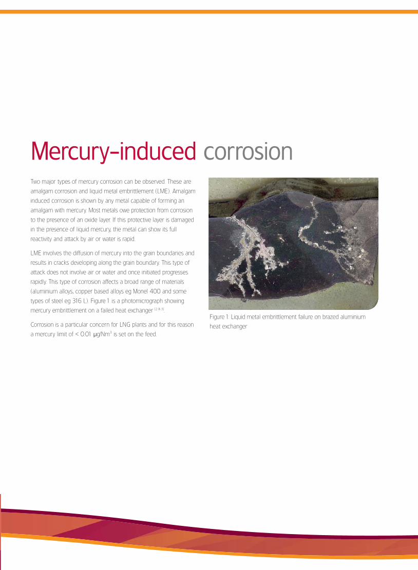
LME involves the diffusion of mercury into the grain boundaries and
results in cracks developing along the grain boundary. This type of
attack does not involve air or water and once initiated progresses
rapidly. This type of corrosion affects a broad range of materials
(aluminium alloys, copper based alloys eg Monel 400 and some
types of steel eg 316 L). Figure 1 is a photomicrograph showing
mercury embrittlement on a failed heat exchanger [2 & 3].
Corrosion is a particular concern for LNG plants and for this reason
a mercury limit of < 0.01 µg/Nm3 is set on the feed.
Figure 1: Liquid metal embrittlement failure on brazed aluminium
heat exchanger
JM_257 Puraspec LNG brochure v4 13/4/07 14:47 Page 6

Health and safety issues
Atmospheric measurements carried out during maintenance
on the gas fields in northeast Netherlands have found
localized levels of mercury as high as 1500 µg/Nm3 when
cleaning tanks and filters [5].
Mercury is a toxic metal and has a relatively high vapour
pressure. Consequently, on opening mercury contaminated
equipment, workers will be exposed to mercury vapour levels
well in excess of the Threshold Limiting Value (TLV) and the
Maximum Allowable Concentration (MAC). Suitable personal
protective equipment is required during maintenance work. The
European Union Scientific Committee on Occupational Exposure
Limits proposes 0.02 mg/m3 as an 8-hour time-weighted
average and 0.01 mg/l in blood as biological limit values [4].
JM_257 Puraspec LNG brochure v4 13/4/07 14:47 Page 7
Disposal of mercurycontaminated pipe work
mercury can penetrate up to 1mm and many smelters set a limit of
2 mg/kg for scrap steel to avoid damage to the off-gas clean-up
filters. Table 2 gives the levels of mercury found on a sample of
contaminated steel from a failed reactor [6].
Because of the ease with which mercury bonds to metal surfaces,
pipe work used to carry mercury containing gas becomes coated
with mercury. In extreme cases a “mirror” surface is formed. This
makes it harder to dispose of scrap steel. Tests have shown that
Table 2: Mercury content near surface of a failed steel reactor.
Depth (mm) Concentration (µµg/g)
Surface to 0.3 0.8
0.3 to 0.4 0.2
0.4 to 0.5 0.1
JM_257 Puraspec LNG brochure v4 13/4/07 14:47 Page 8
Emissions to the environmentMost of the operational concerns about mercury are focussed on the
problems it causes for the hydrocarbon product streams. However,
the surprisingly high volatility of mercury means that it is released to
the atmosphere during the processing stages. Thus, up to half of the
mercury present in the raw gas is likely to be removed on the acid
gas removal and drying stages. Acid gas removal stripper gas is
released to the atmosphere either directly or via an incinerator.
Molecular sieve regeneration gas is usually added to the fuel gas.
EU Directive 2000/76/EC sets the air emission limiting value for
incineration plants of 0.05 mg/m3, as an average value over a
minimum period of 30 minutes and a maximum of 8 hours.
There is a risk that fuel gas derived from molecular sieve
regeneration gas may exceed this limit.
TEG and MEG flash gas and regeneration gas is released to the
atmosphere. All of these releases are from low level stacks and
studies have shown that there is an accumulation of mercury in
fauna and flora adjacent to the plants processing mercury
containing gas [7].
JM_257 Puraspec LNG brochure v4 13/4/07 14:47 Page 9
Mercury in product streamsThere are increasing concerns about the presence of mercury in
the feedstocks supplied to petrochemical plants (LPG and naphtha).
Here the worries are not only for corrosion of cryogenic equipment
but also the poisoning of precious metal catalysts. Many users are
setting limits of < 1ppb.
A further complication is the risk of contamination during shipment.
This can easily happen if the same vessel is used for shipments of
clean and mercury containing product. Mercury is only slowly
removed from contaminated pipework.
JM_257 Puraspec LNG brochure v4 13/4/07 14:47 Page 10
Location of MRUwill go to drain. Flash gas and stripper gas from MEG and TEG dryers
is likely to be vented locally.
It is possible to use small mercury removal units to treat some of the
emissions [8].
Location upstream of the driers will reduce some of the mercury
emissions and avoids any delays to start up. However, this location
will carry the risk of fouling by carryover.
Treatment of the raw gas is undoubtedly the preferred location.
This avoids emissions of mercury to the atmosphere and
contamination of plant equipment. This will ensure any NGLs
produced are free from mercury. However, this location is more
of a challenge for the mercury removal absorbent.
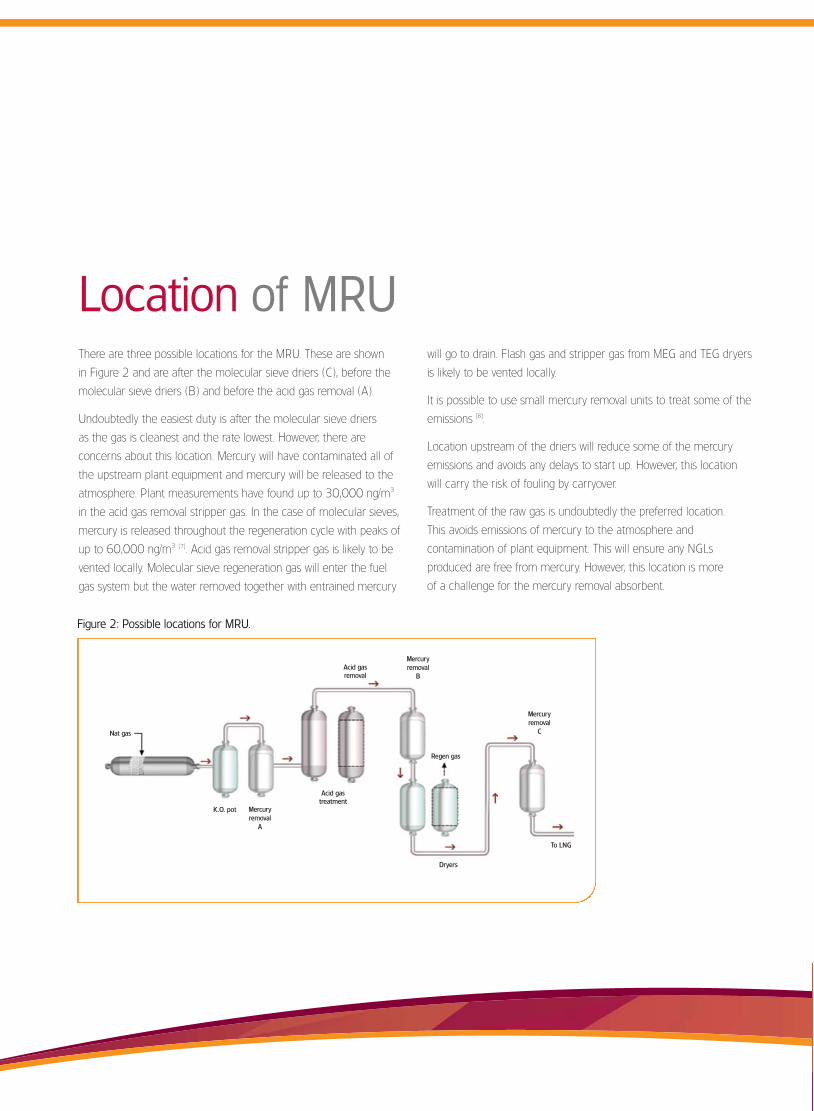
There are three possible locations for the MRU. These are shown
in Figure 2 and are after the molecular sieve driers (C), before the
molecular sieve driers (B) and before the acid gas removal (A).
Undoubtedly the easiest duty is after the molecular sieve driers
as the gas is cleanest and the rate lowest. However, there are
concerns about this location. Mercury will have contaminated all of
the upstream plant equipment and mercury will be released to the
atmosphere. Plant measurements have found up to 30,000 ng/m3
in the acid gas removal stripper gas. In the case of molecular sieves,
mercury is released throughout the regeneration cycle with peaks of
up to 60,000 ng/m3 [7]. Acid gas removal stripper gas is likely to be
vented locally. Molecular sieve regeneration gas will enter the fuel
gas system but the water removed together with entrained mercury
Nat gas
Acid gastreatment
Regen gas
Dryers
To LNG
Acid gas removal
Mercury removal
B
Mercury removal
C
Mercury removal
A
K.O. pot
Figure 2: Possible locations for MRU.
JM_257 Puraspec LNG brochure v4 13/4/07 14:47 Page 11
Choice of absorbentTraditionally mercury has been removed using sulphur impregnated
carbon. Typically this will contain 10 to 15% w/w sulphur and mercury
is removed by reaction to form HgS. The reactivity with mercury
depends on the allotrope of sulphur present on the carbon. This can
vary from S8 down to S2 with the lower allotropes having higher
activity but these are the harder to form as they require higher
impregnation temperatures [10]. There are other problems inherent
with this type of absorbent.
• Sulphur Loss – sulphur is lost in service by sublimation and
leaching by liquid hydrocarbons. LNG operators have found sulphur
at the top of the bed of a discharged reactor to be as low as 3.7
to 4.2%. Whilst this is still enough to trap mercury there must be
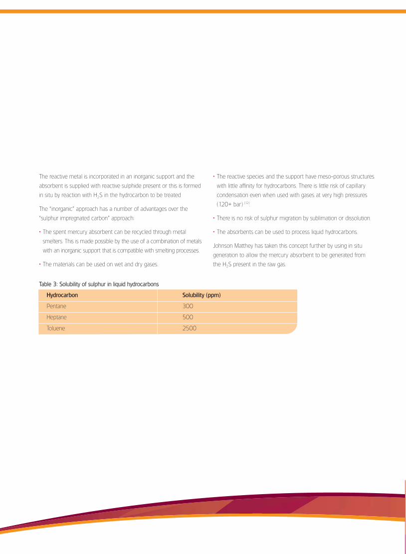
a concern as to where the sulphur has gone. Table 3 shows the
solubility of sulphur in liquid hydrocarbons.
• Capillary condensation – the nature of the material and the
method of manufacture give a high surface area support (typically
1000 m2/g with average pore size <20Å). This type of material is
vulnerable to capillary condensation by C5+ hydrocarbons with
aromatic compounds a particular concern [11].
• Start up delays – carbon based absorbents need to equilibrate
with the process gas and can release sulphur during
commissioning. This can delay introduction of feed gas
to the cryogenic plant for up to three days. On a 10,000
tpd plant this is worth $5.6 M in lost production.
• Disposal of spent absorbent – the material cannot be sent for
landfill in most locations. It is difficult to free the spent absorbent
from hydrocarbons and mercury can only be removed by a
thermal process.
• Handling – the material is likely to contain dust and carries the risk
of self heating.
Recognition of these problems has lead to the development of
inorganic based absorbents. These rely on the high reactivity
of mercury with the metal sulphides of certain variable valency
metal sulphides.
Hg + MxSy = MxSa + HgS
JM_257 Puraspec LNG brochure v4 13/4/07 14:47 Page 12
The reactive metal is incorporated in an inorganic support and the
absorbent is supplied with reactive sulphide present or this is formed
in situ by reaction with H2S in the hydrocarbon to be treated
The “inorganic” approach has a number of advantages over the
“sulphur impregnated carbon” approach:
• The spent mercury absorbent can be recycled through metal
smelters. This is made possible by the use of a combination of metals
with an inorganic support that is compatible with smelting processes.
• The materials can be used on wet and dry gases.
• The reactive species and the support have meso-porous structures
with little affinity for hydrocarbons. There is little risk of capillary
condensation even when used with gases at very high pressures
(120+ bar) [12].
• There is no risk of sulphur migration by sublimation or dissolution.
• The absorbents can be used to process liquid hydrocarbons.
Johnson Matthey has taken this concept further by using in situ
generation to allow the mercury absorbent to be generated from
the H2S present in the raw gas.
Table 3: Solubility of sulphur in liquid hydrocarbons
Hydrocarbon Solubility (ppm)
Pentane 300
Heptane 500
Toluene 2500
JM_257 Puraspec LNG brochure v4 13/4/07 14:47 Page 13
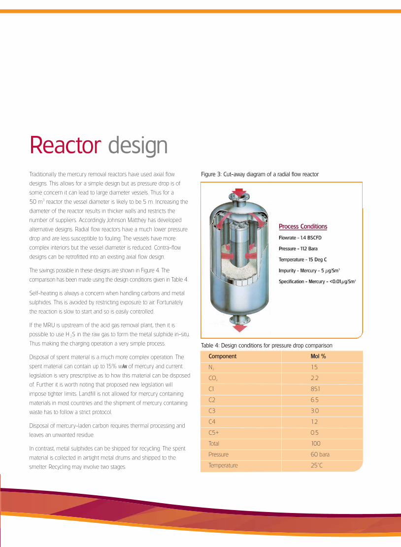
Traditionally the mercury removal reactors have used axial flow
designs. This allows for a simple design but as pressure drop is of
some concern it can lead to large diameter vessels. Thus for a
50 m3 reactor the vessel diameter is likely to be 5 m. Increasing the
diameter of the reactor results in thicker walls and restricts the
number of suppliers. Accordingly Johnson Matthey has developed
alternative designs. Radial flow reactors have a much lower pressure
drop and are less susceptible to fouling. The vessels have more
complex interiors but the vessel diameter is reduced. Contra-flow
designs can be retrofitted into an existing axial flow design.
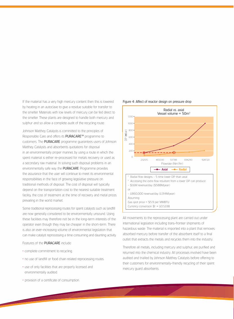
The savings possible in these designs are shown in Figure 4. The
comparison has been made using the design conditions given in Table 4.
Self-heating is always a concern when handling carbons and metal
sulphides. This is avoided by restricting exposure to air. Fortunately
the reaction is slow to start and so is easily controlled.
If the MRU is upstream of the acid gas removal plant, then it is
possible to use H 2S in the raw gas to form the metal sulphide in-situ.
Thus making the charging operation a very simple process.
Disposal of spent material is a much more complex operation. The
spent material can contain up to 15% w/w of mercury and current
legislation is very prescriptive as to how this material can be disposed
of. Further it is worth noting that proposed new legislation will
impose tighter limits. Landfill is not allowed for mercury containing
materials in most countries and the shipment of mercury containing
waste has to follow a strict protocol.
Disposal of mercury-laden carbon requires thermal processing and
leaves an unwanted residue.
In contrast, metal sulphides can be shipped for recycling. The spent
material is collected in airtight metal drums and shipped to the
smelter. Recycling may involve two stages.
Reactor design
Table 4: Design conditions for pressure drop comparison
Component Mol %
N2 1.5
CO2 2.2
C1 85.1
C2 6.5
C3 3.0
C4 1.2
C5+ 0.5
Total 100
Pressure 60 bara
Temperature 25°C
Figure 3: Cut-away diagram of a radial flow reactor
JM_257 Puraspec LNG brochure v4 13/4/07 14:47 Page 14
If the material has a very high mercury content then this is lowered
by heating in an autoclave to give a residue suitable for transfer to
the smelter. Materials with low levels of mercury can be fed direct to
the smelter. These plants are designed to handle both mercury and
sulphur and so allow a complete audit of the recycling route.
Johnson Matthey Catalysts is committed to the principles of
Responsible Care and offers its PURACARESM programme to
customers. The PURACARE programme guarantees users of Johnson
Matthey Catalysts and absorbents quotations for disposal
in an environmentally proper manner, by using a route in which the
spent material is either re-processed for metals recovery or used as
a secondary raw material. In solving such disposal problems in an
environmentally safe way the PURACARE Programme provides
the assurance that the user will continue to meet its environmental
responsibilities in the face of growing legislative pressure on
traditional methods of disposal. The cost of disposal will typically
depend on the transportation cost to the nearest suitable treatment
facility, the cost of treatment at the time of recovery and metal prices
prevailing in the world market.
Some traditional reprocessing routes for spent catalysts such as landfill
are now generally considered to be environmentally unsound. Using
these facilities may therefore not be in the long-term interests of the
operator even though they may be cheaper in the short-term. There
is also an ever-increasing volume of environmental legislation that
can make catalyst reprocessing a time consuming and daunting activity.
Features of the PURACARE include:
• complete commitment to recycling.
• no use of landfill or food chain related reprocessing routes.
• use of only facilities that are properly licensed and
environmentally audited.
• provision of a certificate of consumption.
All movements to the reprocessing plant are carried out under
international legislation including trans-frontier shipments of
hazardous waste. The material is imported into a plant that removes
absorbed mercury before transfer of the absorbent itself to a final
outlet that extracts the metals and recycles them into the industry.
Therefore all metals, including mercury and sulphur, are purified and
returned into the chemical industry. All processes involved have been
audited and trialled by Johnson Matthey Catalysts before offering to
their customers for environmentally-friendly recycling of their spent
mercury guard absorbents.
Radial vs. axialVessel volume = 50m3
232515 465030 537381 694290 928720
Flowrate (Nm3/hr)
* Radial flow designs ~ 5 time lower DP than axial
* Accessing the extra flow resultant from a lower DP can produce:
~ $1,6M revenue/day ($588M/year)
or
~ £860,000 revenue/day (£314M/year)
Assuming:
Gas spot price = $5.9 per MMBTU
Currency conversion $1 = £0.5338
1200
1000
800
600
400
200
0
DP
(mba
r)
Axial Radial
Figure 4: Affect of reactor design on pressure drop
JM_257 Puraspec LNG brochure v4 13/4/07 14:47 Page 15
6 Marsch, H-D. ”Explosion of Synloop Ammonia Separator” AIChE
Technical Manual 8-15 Vol 31 1991.
7 Spiric, Z., Srebocean, E., “Environmental Monitoring-Mercury
Concentration in Ambient Air and Hares at GTP Molve Area”
Workshop on Mercury in the Idjija Region and the Northern
Adriatic, Portoroz, Slovenia, May 13-16, 2001.
8 Carnell, P. J. H., Openshaw, P. J. ”Mercury Distribution on Gas
Processing Plants” 83rd Annual GPA convention March 14-17,
2004, San Antonio, TX, USA
9 Carnell, P., J., H. and Foster, A. “Control of Mercury Emissions
from Gas Processing Plant Dryers” Mercury 2006 Conference
on Mercury as a global pollutant, Madison, USA, August 6–11,
2006.
10 Carnell, P. J. H., Openshaw, P. J. ”Mercury Distribution on Gas
Processing Plants” 83rd Annual GPA convention March 14-17,
2004, San Antonio, TX, USA
11 Liu, W., Vidic. R., D. and Brown, T., D. “Optimization of Sulfur
Impregnation Protocol of Activated Carbon-Based Sorbents
for Gas-Phase Mercury Removal” Environmental Science &
Technology, Vol 32, No 4, 531-538, 1998.
12 Cameron, C. J., Bartel, Y., Sarrazin, P., “Mercury Removal from
Wet Gas” 73rd Annual GPA Convention March 7-9, 1994,
New Orleans, LA, USA.
13 Carnell, P. J. H., Openshaw, P. J. and Rhodes, E. F., “Fixed-Bed
Technology Purifies Rich Gas With H2S, Hg” Oil & Gas Journal,
May 1999.
Development of new high activity mercury removal absorbents allows
greater flexibility in the design of LNG plants. It is now possible to
locate the MRU upstream of the main gas processing plant and thus
avoid mercury emissions and contamination of any co-produced
NGLs. The high activity allows for smaller beds, which coupled with
new reactor designs, allows for savings in compression costs. The
new absorbents can be recycled through metal smelters to give
an auditable and environmentally acceptable route for disposal.
References1 Zettlizer, M., Scholer, H. F., Eiden, R. and Falter, R., “Distribution
of Elemental, Inorganic and Organic Mercury in North German
Gas Condensates and Formation Brines”, Society of Petroleum
Engineers International Symposium on Oilfield Chemistry,
Houston, Texas, February 18-21 1997.
2 Bell, R., “Review of Impact of Mercury on Aluminium Heat
Exchangers” EEPC annual HSE Meeting, Prague, Czech Republic,
October 6-7, 2005.
3 Photomicrograph reproduced courtesy of Chart Energy and
Chemicals.
4 Pirrone, N., and Mahaffey, K. R., “Dynamics of Mercury Pollution
on Regional and Global Scales : Atmospheric Processes and
Human Exposures Around the World” Published by Springer
Science + Business Media, 2005, Chapter 4, 65-80.
5 Boogard, P., J. Journee, H., P. and Van Sittert, N., L., “Effects of
Exposure to Elemental Mercury on the Nervous System and
the Kidneys of Workers Producing Natural Gas” Archives of
Environmental Health, 108–115, Vol 51, 1996.
Conclusion
JM_257 Puraspec LNG brochure v4 13/4/07 14:48 Page 16

PO Box 1Belasis AvenueBillinghamClevelandTS23 1LBUKTel +44 (0)1642 553601Fax +44 (0)1642 522542
Oakbrook TerraceTwo Transam Plaza DriveChicagoIllinois 60181USA
Tel 001 630 268 6300Fax 001 630 268 9797
© 2007 Johnson Matthey Group1148JM/1106/0/AMOG
For further information on Johnson Matthey Catalysts, contact your local sales office or visit our website at www.jmcatalysts.com
PURASPEC is a trademark of the Johnson Matthey Group of companies, PURACARE is a service mark of the Johnson Matthey Group.
www.jmcatalysts.com
JM_257 Puraspec LNG brochure v4 13/4/07 14:47 Page 1