Embed Size (px)
Citation preview
FACULDADE DE
A Requirements Development
Compatible with CMMI
Eduardo
Master in
ACULDADE DE ENGENHARIA DA UNIVERSIDADE DO
A Requirements Development Methodology
ompatible with CMMI
Eduardo Alberto Almeida Espinheira Gomes
Dissertation Report Master in Informatics and Computing Engineering
Supervisor: João Pascoal Faria (PhD)
July 15th, 2009
NIVERSIDADE DO PORTO
A Requirements Development
ompatible with CMMI
Gomes
Informatics and Computing Engineering

A Requirements Development Methodology Compatible with CMMI
Eduardo Alberto Almeida Espinheira Gomes
Dissertation Report Master in Informatics and Computing Engineering
Approved in oral examination by the committee:
Chair: José A. Faria (PhD)
____________________________________________________
External Examiner: Alberto Silva (PhD)
Internal Examiner: João Pascoal Faria (PhD)
July 15th, 2009

4
5
Abstract
This dissertation is part of an organizational effort to continuously improve their processes in order to meet the constant challenges of implementing and maintaining healthcare software solutions.
It was focused on the requirements development methodology used on the Functional Analysis department.
The goal for this dissertation is to improve the requirements development methodology using the CMMI best practices as guiding standard. Aiming to facilitate a future implementation of the CMMI standard at ALERT Life Sciences Computing, SA.
The current workflows and templates used on the Functional Analysis department were
identified and detailed. There are 2 stages: the “Functional Analysis” and “Functional Specification”. Afterwards they were analysed using a customized CMMI based evaluation to detect a set of non-compliances and out of the scope issues.
The proposed workflow was divided in 3 stages: “AS IS”, “TO BE” and “REQ SPEC”.
The new Functional Analysis workflow and documents were proposed to reduce the non-compliances, and implement some general document best practices. The result was evaluated using the same customized CMMI based evaluation to understand and measure the impact obtained.
Along with the rest of the team, the new workflow and templates were thoroughly used
around the world. The result was a very positive overall impact within other teams and customers.
The set goal was completely achieved; the Requirements Development methodology used
is now closer to the CMMI best practices than ever before. Creating a path for the other teams to facilitate a future implementation of the CMMI Standard at ALERT Life Sciences Computing, SA.
6
Resumo
Esta dissertação fez parte de um esforço organizacional de melhoria de processos internos. O objectivo é contribuir para continuar a superar os desafios inerentes à implementação e manutenção de soluções de software para a área da saúde. A dissertação focou-se na metodologia de desenvolvimento de requisitos utilizada no departamento de Análise Funcional.
O objectivo desta dissertação é a melhoria da metodologia usada, à luz das boas práticas
definidas pelo CMMI (Capability Maturity Model Integration), pretendendo facilitar uma futura implementação do CMMI na Alert Life Sciences Computing, SA.
Os processos e documentos usados pelo departamento de Análise Funcional foram
identificados e detalhados. O processo compreende 2 partes: “Functional Analysis” e “Functional Specification”. Posteriormente foram analisados através de um método de avaliação adaptado às condições existentes e baseado no CMMI. Deste modo foi detectado um conjunto de não conformidades e pontos fora do âmbito do departamento.
O processo proposto foi dividido em 3 partes: “AS IS”, “TO BE” e “REQ SPEC”. A nova
metodologia foi proposta para minimizar as não conformidades, aproveitando a oportunidade para implementar algumas boas práticas de documentação. O resultado destas alterações foi avaliado através da mesma matriz usada anteriormente para poder observar o impacto obtido.
Toda a equipa cumpriu e usou a nova metodologia e documentos nos vários clientes, no
mundo inteiro. O resultado foi muito positivo junto das outras equipas e clientes. O objectivo foi claramente atingido. A metodologia de desenvolvimento de requisitos está
mais próxima das boas práticas definidas pelo CMMI. Criando desta forma uma abordagem possível de ser feita noutras equipas para facilitar a futura implementação do CMMI na ALERT Life Sciences Computing, SA.

7
8
Acknowledgements
Special thanks to: - Prof. Pascoal Faria, my supervisor, for the guidance, support and enabling me to
perform this dissertation. - Maria João Azeredo, Business Development Manager, for contributing to the
constant improvement within the company and enabling me to participate on her vision.
- Miguel Paixão, Functional Analysis Team Manager, for his vision, friendship, support, creating the perfect conditions for the work to be performed.
- My team colleagues; Allan Shieh, Catarina Rebelo, César Pinto, Fátima Almeida, Jannine Santos, João Leite, João Silva, Jorge Correia, José Rodrigues, Marco Teixeira, Sílvia Rocha, Soo Magee, Tatiana Lopes e Vítor Sousa; Since 1998 I have worked in very different places and I had many occupations, but without any doubt, this is the most friendly, professional and miscellaneous group of all.
- Ricardo Oliveira, for his availability, personality and document support. - Alexandrina Lemos, Bruno Martins and Luís Ramos, for contributing to my
curiosity regarding the software quality engineering area, and sharing a vision of constant process improvement regarding software development processes.
- Prof. Augusto Sousa, Prof. Jorge Freire de Sousa, Prof. Jaime Villate and Prof. Magalhães Cruz, for reinforcing my expectations and standards teaching.
- To my closest friends, for representing the family that I chose and helping me thrive and learn that many times discomfort simply means growth.
Last but not least to my father, mother, brother and my girlfriend for continuously
reminding me of the most important things in life - them.
Eduardo Espinheira

9
10
Contents
1 Introduction ............................................................................................................... 1
1.1 Context ............................................................................................................... 1
1.2 Project ................................................................................................................ 1
1.3 Motivation and Goals ......................................................................................... 2
1.4 Report Structure ................................................................................................. 2
2 Current Requirements Development Methodology .................................................. 3
2.1 Software Development Workflow ...................................................................... 3
2.2 Functional Analysis Workflow ........................................................................... 4
2.3 Functional Analysis Templates ........................................................................... 6
2.4 Conclusions ........................................................................................................ 7
3 CMMI Overview ....................................................................................................... 8
3.1 Introduction ........................................................................................................ 8
3.2 CMMI ................................................................................................................. 9
3.3 CMMI levels ...................................................................................................... 9
3.4 Appraisals ......................................................................................................... 10
3.5 Performance Results of CMMI-based Process Improvement .......................... 12
3.6 Conclusions ...................................................................................................... 12
4 CMMI based Evaluation of the Current Methodology ........................................... 13
4.1 Introduction ...................................................................................................... 13
4.2 Process Area Definition .................................................................................... 13
4.3 Evaluation Definition ....................................................................................... 14
4.4 Evaluation Matrix ............................................................................................. 16
4.5 CMMI Compliance Analysis of the Current Methodology.............................. 16
4.6 Conclusions ...................................................................................................... 21
5 Proposed Requirements Development Methodology ............................................. 23
5.1 Functional Analysis Workflow ......................................................................... 23
5.2 Functional Analysis Templates ......................................................................... 24
5.2.1 AS IS template .......................................................................................... 24
11
5.2.2 TO BE template ........................................................................................ 25
5.2.3 REQ SPEC template ................................................................................. 26
5.3 CMMI Compliance Analysis of the Proposed Methodology ........................... 26
5.4 Conclusions ...................................................................................................... 29
6 Implementation ....................................................................................................... 31
6.1 Project .............................................................................................................. 31
6.2 AS IS stage ....................................................................................................... 31
6.2.1 AS IS Workflows Engineering .................................................................. 32
6.2.2 AS IS Overall Feedback ........................................................................... 33
6.3 TO BE stage ..................................................................................................... 34
6.3.1 TO BE Workflows Engineering ................................................................ 34
6.3.2 TO BE Overall Feedback .......................................................................... 35
6.4 REQ SPEC stage in other projects ................................................................... 35
6.4.1 REQ SPEC Definition Engineering .......................................................... 36
6.4.2 REQ SPEC Overall Feedback ................................................................... 37
6.5 Conclusions ...................................................................................................... 37
7 Conclusions and Future Work ................................................................................. 38
7.1 Goal Achievement ............................................................................................ 38
7.2 Future Work ...................................................................................................... 39
Bibliography ................................................................................................................... 40
12
List of Figures
Figure 1: Software Development Workflow. ................................................................... 3
Figure 2: Current Functional Analysis Workflow. ........................................................... 5
Figure 3: Functional Analysis document mind map. ....................................................... 6
Figure 4: Functional Specification document mind map. ................................................ 6
Figure 5: CMMI Continuous Implementation. ................................................................ 9
Figure 6: CMMI Staged Implementation....................................................................... 10
Figure 7: CMMI SCAMPI Appraisals. .......................................................................... 11
Figure 8: CMMI Performance Measures from 30 different organizations. ................... 12
Figure 9: CMMI Model Components. ........................................................................... 15
Figure 10: Analysis Ratings. .......................................................................................... 15 Figure 11: Requirements Development Subcomponent count . .................................... 16
Figure 12: Requirements Development Specific Goal 1 Compliance Analysis. ........... 16 Figure 13: Requirements Development Specific Goal 2 Compliance Analysis. ........... 17 Figure 14: Requirements Development Specific Goal 3 Compliance Analysis. ........... 19 Figure 15: Requirements Development Subcomponent Evaluation.. ............................ 21
Figure 16: Requirements Development Compliance Evaluation. ................................. 21
Figure 17: Proposed Functional Analysis Workflow. .................................................... 24
Figure 18: Functional Analysis AS IS document mind map. ......................................... 25
Figure 19: Functional Analysis TO BE document mind map. ....................................... 25
Figure 20: Functional Analysis REQ SPEC document mind map................................. 26
Figure 21: Requirements Development Specific Goal 1 Compliance Analysis. ........... 27 Figure 22: Requirements Development Specific Goal 2 Compliance Analysis. ........... 27 Figure 23: Requirements Development Specific Goal 3 Compliance Analysis. ........... 28 Figure 24: Requirements Development Subcomponent Evaluation. ............................. 29
Figure 25: Requirements Development Compliance Evaluation. ................................. 30
Figure 26: “AS IS” stage within Functional Analysis Methodology. ............................ 31
Figure 27: Relation between Hospital units. .................................................................. 32
Figure 28: UML Activity Diagram example. ................................................................. 33
Figure 29: “AS IS” Workflow mind map. ..................................................................... 33
Figure 30: “TO BE” stage within Functional Analysis Methodology. .......................... 34
Figure 31: “TO BE” Workflow mind map. .................................................................... 35
Figure 32: “REQ SPEC” stage within Functional Analysis Methodology. ................... 35 Figure 33: UML Use Case Diagram example. ............................................................... 36
Figure 34: REQ SPEC definition mind map. ................................................................. 36
13
Abbreviations
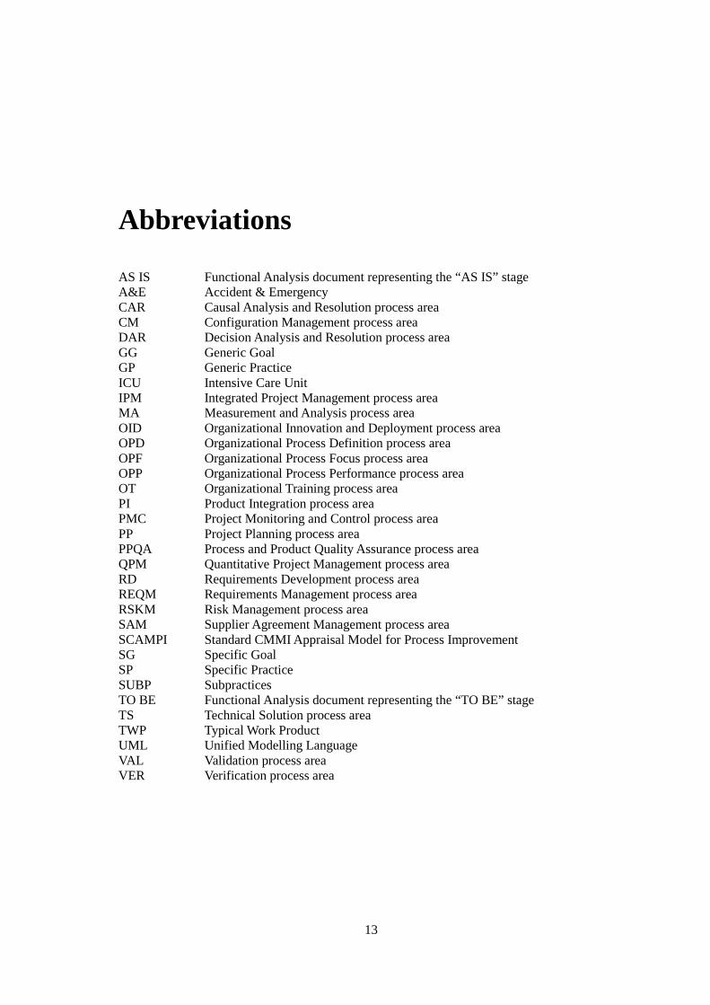
AS IS Functional Analysis document representing the “AS IS” stage A&E Accident & Emergency CAR Causal Analysis and Resolution process area CM Configuration Management process area DAR Decision Analysis and Resolution process area GG Generic Goal GP Generic Practice ICU Intensive Care Unit IPM Integrated Project Management process area MA Measurement and Analysis process area OID Organizational Innovation and Deployment process area OPD Organizational Process Definition process area OPF Organizational Process Focus process area OPP Organizational Process Performance process area OT Organizational Training process area PI Product Integration process area PMC Project Monitoring and Control process area PP Project Planning process area PPQA Process and Product Quality Assurance process area QPM Quantitative Project Management process area RD Requirements Development process area REQM Requirements Management process area RSKM Risk Management process area SAM Supplier Agreement Management process area SCAMPI Standard CMMI Appraisal Model for Process Improvement SG Specific Goal SP Specific Practice SUBP Subpractices TO BE Functional Analysis document representing the “TO BE” stage TS Technical Solution process area TWP Typical Work Product UML Unified Modelling Language VAL Validation process area VER Verification process area

14
1
1 Introduction
1.1 Context
The ALERT Group of Companies is fully committed to the development, distribution and implementation of healthcare software, to create paper-free clinical environments. The software comprises a set of modules to cover different areas and types of clinical facilities. The product is implemented in different markets in different countries and continents.
The Functional Analysis department is responsible for conducting meetings and studies at
the customer, concerning clinical and non-clinical processes and document workflows. The output of these meetings and studies is composed by documents. This is where the customer needs are identified and defined in detail.
ALERT Life Sciences Computing, SA is continuously improving the software
development process in order to meet the constant challenges of implementing and maintaining healthcare software solutions. Recently CMMI (Capability Maturity Model® Integration) was selected as the standard to be used on this process improvement. This dissertation is a part of that organization effort, specifically for the requirements development methodology used on the Functional Analysis department.
1.2 Project
The purpose of this dissertation is to analyze and improve the requirements development methodology used in ALERT Life Sciences Computing, SA, specifically the role of the Functional Analysis department.
This dissertation can be divided in 4 stages: identification of the problem, study of the
solutions available, solution proposal and test/implementation. The 1st stage consists of a detailed analysis, using CMMI as the standard, of the workflows
and templates used at the Functional Analysis department. The 2nd stage is a CMMI overview. The 3rd stage is the set of changes identified to improve the methodology previously
analyzed.
2
The 4th stage aims to implement the changes identified and test the new methodology within the department in a direct contact with the customers.
This project aims to facilitate a future implementation of CMMI within the company, starting by the requirements development.
1.3 Motivation and Goals
The goal for this dissertation is to improve the current requirements development methodology by the Functional Analysis department, using the CMMI best practices as guiding standard. In order to facilitate a future implementation of the CMMI standard at ALERT Life Sciences Computing, SA.
1.4 Report Structure
The first chapter of this document, Introduction, provides general information about the Dissertation. The context and the theme are presented together with the motivation and goals previously established. The chapter ends with the description of the report structure.
The second chapter, Current Requirements Development Methodology, describes a
general overview of the situation at the beginning of this dissertation. To do so, the company software development workflow is explained to allow a deeper top-down approach to the functional analysis workflows and documents.
The third chapter, CMMI Overview, contains the research about this standard, used as the
cornerstone to improve the processes used within the Functional Analysis department. The fourth chapter, CMMI based Evaluation of the Current Methodology, presents the
analysis undertook to identify the gap between the workflows and templates defined, and the goal previously established of the standard implementation.
The fifth chapter, Proposed Requirements Development Methodology, details the
solution defined to bridge the gap identified on the fourth chapter. The sixth chapter, Implementation, provides an insight look of an on-site operation of the
new workflows and templates, implemented on a real project. The seventh and final chapter, Conclusions and Future Work, describes the conclusions
drawn from all the work performed throughout the project. It sets the direction for the future to continue the first approach to an informal implementation of CMMI at ALERT.
3
2 Current Requirements Development Methodology
2.1 Software Development Workflow
The software development process at ALERT has a set of steps to meet the needs of the healthcare industry and the company strategy.
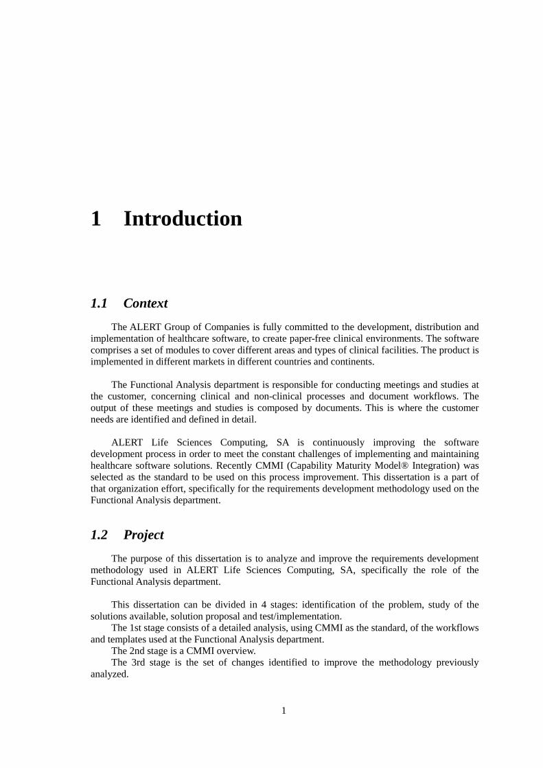
The different stages are as follows:
Figure 1: Software Development Workflow.
Every stage is performed by a specific department and in some specific cases their work is done simultaneously.
The Product Conceptualization consists on the definition of the core concepts for the product. Usually one of two situations occur for this team to be called upon: new
4
product/module/profile or a requirement with a big impact on the product. They are the source for many of the requirements developed. This Concept Design team is mostly composed by professionals with a clinical or communication design expertise.
The Functional Analysis begins his work with one of two conditions: conceptualization
input for a new product/module/profile or a new customer. On either case these professionals will have to go to one or more customers to understand how they work and/or they could work. They will be defining and documenting the requirements to be developed. This team is mostly composed by professionals with computer engineering or process expertise.
The Interface Design determines how the interface will be. Their work is based on the
requirements identified previously and design guidelines knowledge-based. They are responsible for the creation of each icon, button and menu; they also manage the usability and product navigation. This team is mostly composed by professionals with communication design expertise.
The Functional Architecture analyses each product requirement and interface design to
meet specific guidelines for the product architecture, keeping in mind the functional usability, standardization and interaction between the several products and modules. This team is composed by professionals with computer engineering expertise.
The Technical Architecture decides the technical solutions for the product. They are
responsible for the definition of the overall product architecture. Their focus is the technological potential and product performance. This team is composed by professionals with computer engineering expertise.
The Development consists on the implementation of the requirements and interfaces after
the definition and validation of the functional and technical architecture. They are responsible for all the product development. This team is composed by professionals with computer engineering expertise.
The Content team gathers, defines and validates all the clinical content present throughout
the products. Their work goes from text menus and report templates to triage protocols. This team is composed by professionals with clinical or scientific expertise.
The Language department is responsible for the translation of all the clinical or functional
texts to the several languages on which the product is available. They also develop, write, validate and translate the manuals for the different products and versions. This team is mostly composed by professionals with foreign languages expertise.
The Versioning team controls the versions for each set of modules and developments.
They are responsible for the overall versioning of the products. This team is composed by professionals with computer engineering expertise.
The Quality Control team tests every single development within different environments to
guarantee the stability of the product. This team is mostly composed by professionals with computer engineering expertise.
Validation from all teams is mandatory for product release.
2.2 Functional Analysis Workflow
Business Analysis is the set of tasks, knowledge, and techniques required to identify business needs and determine solutions to business problems. Solutions often include a systems
5
development component, but may also consist of process improvement or organizational change. (1)
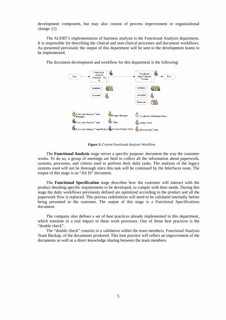
The ALERT’s implementation of business analysis is the Functional Analysis department. It is responsible for describing the clinical and non-clinical processes and document workflows. As presented previously the output of this department will be sent to the development teams to be implemented.
The document development and workflow for this department is the following:
Figure 2: Current Functional Analysis Workflow.
The Functional Analysis stage serves a specific purpose: document the way the customer works. To do so, a group of meetings are held to collect all the information about paperwork, systems, processes, and criteria used to perform their daily tasks. The analysis of the legacy systems used will not be thorough since this task will be continued by the Interfaces team. The output of this stage is an “AS IS” document.
The Functional Specification stage describes how the customer will interact with the
product detailing specific requirements to be developed, to comply with their needs. During this stage the daily workflows previously defined are optimized according to the product and all the paperwork flow is replaced. This process redefinition will need to be validated internally before being presented to the customer. The output of this stage is a Functional Specifications document.
The company also defines a set of best practices already implemented in this department,
which translate in a real impact to these work processes. One of those best practices is the “double check”.
The “double check” consists in a validation within the team members, Functional Analysis Team Backup, of the documents produced. This best practice will reflect an improvement of the documents as well as a direct knowledge sharing between the team members.
6
2.3 Functional Analysis Templates
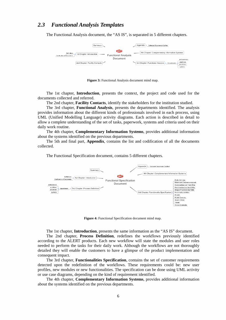
The Functional Analysis document, the “AS IS”, is separated in 5 different chapters.
Figure 3: Functional Analysis document mind map.
The 1st chapter, Introduction, presents the context, the project and code used for the documents collected and referred.
The 2nd chapter, Facility Contacts, identify the stakeholders for the institution studied. The 3rd chapter, Functional Analysis, presents the departments identified. The analysis
provides information about the different kinds of professionals involved in each process, using UML (Unified Modelling Language) activity diagrams. Each action is described in detail to allow a complete understanding of the set of tasks, paperwork, systems and criteria used on their daily work routine.
The 4th chapter, Complementary Information Systems, provides additional information about the systems identified on the previous departments.
The 5th and final part, Appendix, contains the list and codification of all the documents collected.
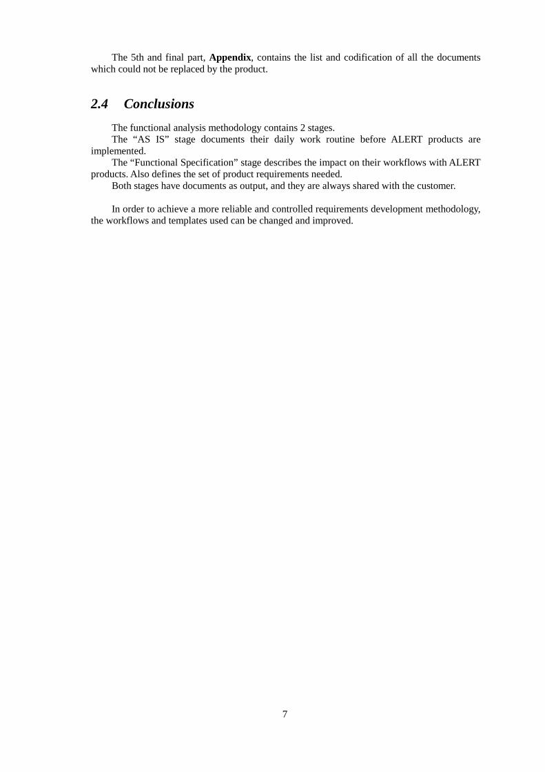
The Functional Specification document, contains 5 different chapters.
Figure 4: Functional Specification document mind map.
The 1st chapter, Introduction, presents the same information as the “AS IS” document. The 2nd chapter, Process Definition, redefines the workflows previously identified
according to the ALERT products. Each new workflow will state the modules and user roles needed to perform the tasks for their daily work. Although the workflows are not thoroughly detailed they will enable the customers to have a glimpse of the product implementation and consequent impact.
The 3rd chapter, Functionalities Specification, contains the set of customer requirements detected upon the redefinition of the workflows. These requirements could be: new user profiles, new modules or new functionalities. The specification can be done using UML activity or use case diagrams, depending on the kind of requirement identified.
The 4th chapter, Complementary Information Systems, provides additional information about the systems identified on the previous departments.
7
The 5th and final part, Appendix, contains the list and codification of all the documents which could not be replaced by the product.
2.4 Conclusions
The functional analysis methodology contains 2 stages. The “AS IS” stage documents their daily work routine before ALERT products are
implemented. The “Functional Specification” stage describes the impact on their workflows with ALERT
products. Also defines the set of product requirements needed. Both stages have documents as output, and they are always shared with the customer. In order to achieve a more reliable and controlled requirements development methodology,
the workflows and templates used can be changed and improved.
8
3 CMMI Overview
3.1 Introduction
Due to the critical nature of its operations, the healthcare sector has regulations and standards. From the very start, ALERT® adopted these international standards in order to comply with legal requirements along with other certifications.
Therefore, ALERT® follows: - International standards of individual clinical information created by the Health Insurance
Portability and Accountability Act (HIPAA) that are superintended by the U.S.A. Ministry of Health (U.S. Department of Health and Human Services) and adopted by the majority of countries;
- Redundancy regulations and has crisis machines that ensure the continuity of healthcare services if electric or communication faults occur when using ALERT®;
- International standards for HL7 healthcare software development, and is an active member of this organization. ALERT has 22 HL7 certified Engineers;
- Integrating the Healthcare Enterprise (IHE) interoperability norms, and participates in international interoperability demonstration exercises, such as the Healthcare Information Technology Standards Panel (HITSP). ALERT was a pioneer in using these standards in Portugal, which ensure interoperability and independence of clinical applications. Additionally, in using these standards, ALERT has pressured its competitors, and complementary applications suppliers, to equally use them;
- Standard nomenclature for LOINC laboratories; - SNOMED CT, ICD9/ACD10 and ICPC2 standard nomenclature; - ICNP nursing nomenclature; - Clinical Document Architecture (CDA) standards. - ALERT implemented a Quality Environmental and Occupational Health and Safety
integrated management system, and is now a certified company according to ISO 9001:2000 (Quality Management), ISO 14001:2004 (Environmental Management) standards and OHSAS 18001:2008 (Occupational Health and Safety Management) specifications.
The company also started implementing a management system for its R&D&I (Research, Development and Innovation) activities in order to achieve NP 4457:2007 certification.
With software development as their core business, it is one of the next strategic goals to implement CMMI (Capability Maturity Model® Integration) within ALERT Life Sciences Computing, SA.
9
3.2 CMMI
CMMI stands for Capability Maturity Model® Integration it is a process improvement approach that provides organizations with the essential elements of effective processes.
Usually it is used to guide process improvement across a project, a division, or an entire organization. CMMI helps integrate traditionally separate organizational functions, set process improvement goals and priorities, provide guidance for quality processes, and provide a point of reference for appraising current processes. (2)
The CMMI model is developed by the CMMI project, which aimed to improve the usability of maturity models by integrating many different models into one framework. The project consisted of members from industry, government and the Carnegie Mellon Software Engineering Institute (SEI). The main sponsors included the Office of the Secretary of Defense (OSD) and the National Defense Industrial Association.
CMMI is the successor of the Capability Maturity Model (CMM) or Software CMM. The CMM was developed from 1987 until 1997. In 2002, CMMI Version 1.1 was released. Version 1.2 followed in August 2006. (3)
3.3 CMMI levels
Levels are used in CMMI to describe an evolutionary path recommended for an organization that wants to improve the processes it uses to develop and maintain its products and services. Levels can also be the outcome of the rating activity of appraisals. (4) Appraisals can be performed for organizations that comprise entire (usually small) companies, or for smaller groups such as a group of projects or a division within a company.
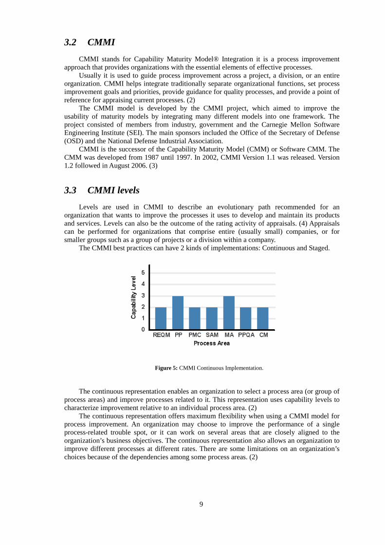
The CMMI best practices can have 2 kinds of implementations: Continuous and Staged.
Figure 5: CMMI Continuous Implementation.
The continuous representation enables an organization to select a process area (or group of process areas) and improve processes related to it. This representation uses capability levels to characterize improvement relative to an individual process area. (2)
The continuous representation offers maximum flexibility when using a CMMI model for process improvement. An organization may choose to improve the performance of a single process-related trouble spot, or it can work on several areas that are closely aligned to the organization’s business objectives. The continuous representation also allows an organization to improve different processes at different rates. There are some limitations on an organization’s choices because of the dependencies among some process areas. (2)
10
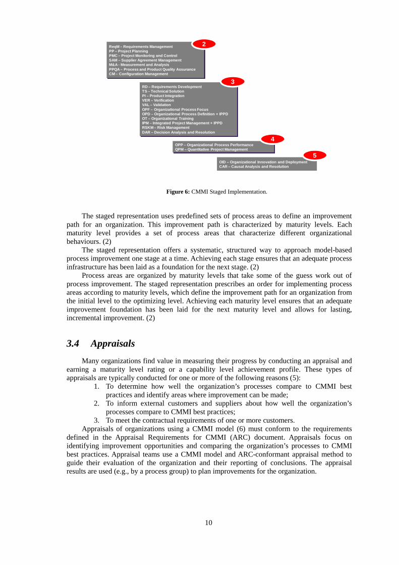
Figure 6: CMMI Staged Implementation.
The staged representation uses predefined sets of process areas to define an improvement path for an organization. This improvement path is characterized by maturity levels. Each maturity level provides a set of process areas that characterize different organizational behaviours. (2)
The staged representation offers a systematic, structured way to approach model-based process improvement one stage at a time. Achieving each stage ensures that an adequate process infrastructure has been laid as a foundation for the next stage. (2)
Process areas are organized by maturity levels that take some of the guess work out of process improvement. The staged representation prescribes an order for implementing process areas according to maturity levels, which define the improvement path for an organization from the initial level to the optimizing level. Achieving each maturity level ensures that an adequate improvement foundation has been laid for the next maturity level and allows for lasting, incremental improvement. (2)
3.4 Appraisals
Many organizations find value in measuring their progress by conducting an appraisal and earning a maturity level rating or a capability level achievement profile. These types of appraisals are typically conducted for one or more of the following reasons (5):
1. To determine how well the organization’s processes compare to CMMI best practices and identify areas where improvement can be made;
2. To inform external customers and suppliers about how well the organization’s processes compare to CMMI best practices;
3. To meet the contractual requirements of one or more customers. Appraisals of organizations using a CMMI model (6) must conform to the requirements
defined in the Appraisal Requirements for CMMI (ARC) document. Appraisals focus on identifying improvement opportunities and comparing the organization’s processes to CMMI best practices. Appraisal teams use a CMMI model and ARC-conformant appraisal method to guide their evaluation of the organization and their reporting of conclusions. The appraisal results are used (e.g., by a process group) to plan improvements for the organization.
ReqM – Requirements ManagementPP – Project PlanningPMC – Project Monitoring and ControlSAM – Supplier Agreement ManagementM&A - Measurement and AnalysisPPQA – Process and Product Quality AssuranceCM – Configuration Management
2
RD – Requirements DevelopmentTS – Technical SolutionPI – Product IntegrationVER – VerificationVAL – ValidationOPF – Organizational Process FocusOPD – Organizational Process Definition + IPPDOT – Organizational TrainingIPM – Integrated Project Management + IPPDRSKM – Risk ManagementDAR – Decision Analysis and Resolution
OPP – Organizational Process PerformanceQPM – Quantitative Project Management
OID – Organizational Innovation and DeploymentCAR – Causal Analysis and Resolution
3
5
4
11
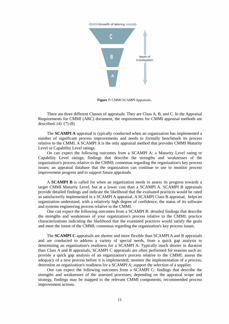
Figure 7: CMMI SCAMPI Appraisals.
There are three different Classes of appraisals. They are Class A, B, and C. In the Appraisal Requirements for CMMI (ARC) document, the requirements for CMMI appraisal methods are described. (4) (7) (8)
The SCAMPI A appraisal is typically conducted when an organization has implemented a
number of significant process improvements and needs to formally benchmark its process relative to the CMMI. A SCAMPI A is the only appraisal method that provides CMMI Maturity Level or Capability Level ratings.
On can expect the following outcomes from a SCAMPI A: a Maturity Level rating or Capability Level ratings; findings that describe the strengths and weaknesses of the organization's process relative to the CMMI; consensus regarding the organization's key process issues; an appraisal database that the organization can continue to use to monitor process improvement progress and to support future appraisals.
A SCAMPI B is called for when an organization needs to assess its progress towards a
target CMMI Maturity Level, but at a lower cost than a SCAMPI A. SCAMPI B appraisals provide detailed findings and indicate the likelihood that the evaluated practices would be rated as satisfactorily implemented in a SCAMPI A appraisal. A SCAMPI Class B appraisal, helps an organization understand, with a relatively high degree of confidence, the status of its software and systems engineering process relative to the CMMI.
One can expect the following outcomes from a SCAMPI B: detailed findings that describe the strengths and weaknesses of your organization's process relative to the CMMI; practice characterizations indicating the likelihood that the examined practices would satisfy the goals and meet the intent of the CMMI; consensus regarding the organization's key process issues.
The SCAMPI C appraisals are shorter and more flexible than SCAMPI A and B appraisals
and are conducted to address a variety of special needs, from a quick gap analysis to determining an organization's readiness for a SCAMPI A. Typically much shorter in duration than Class A and B appraisals, SCAMPI C appraisals are often performed for reasons such as: provide a quick gap analysis of an organization's process relative to the CMMI; assess the adequacy of a new process before it is implemented; monitor the implementation of a process; determine an organization's readiness for a SCAMPI A; support the selection of a supplier.
One can expect the following outcomes from a SCAMPI C: findings that describe the strengths and weaknesses of the assessed processes; depending on the appraisal scope and strategy, findings may be mapped to the relevant CMMI components; recommended process improvement actions.
12
3.5 Performance Results of CMMI-based Process Improvement
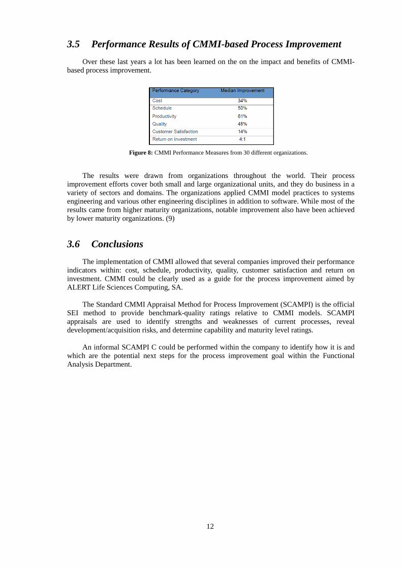
Over these last years a lot has been learned on the on the impact and benefits of CMMI-based process improvement.
Figure 8: CMMI Performance Measures from 30 different organizations.
The results were drawn from organizations throughout the world. Their process improvement efforts cover both small and large organizational units, and they do business in a variety of sectors and domains. The organizations applied CMMI model practices to systems engineering and various other engineering disciplines in addition to software. While most of the results came from higher maturity organizations, notable improvement also have been achieved by lower maturity organizations. (9)
3.6 Conclusions
The implementation of CMMI allowed that several companies improved their performance indicators within: cost, schedule, productivity, quality, customer satisfaction and return on investment. CMMI could be clearly used as a guide for the process improvement aimed by ALERT Life Sciences Computing, SA.
The Standard CMMI Appraisal Method for Process Improvement (SCAMPI) is the official
SEI method to provide benchmark-quality ratings relative to CMMI models. SCAMPI appraisals are used to identify strengths and weaknesses of current processes, reveal development/acquisition risks, and determine capability and maturity level ratings.
An informal SCAMPI C could be performed within the company to identify how it is and
which are the potential next steps for the process improvement goal within the Functional Analysis Department.
13
4 CMMI based Evaluation of the Current Methodology
4.1 Introduction
The Functional Analysis is a fast growing department. Therefore improvement is always welcome and needed. CMMI will be the standard used as guideline.
The CMMI Appraisal is an examination of one or more processes by a trained team of professionals using an appraisal reference model as the basis for determining strengths and weaknesses of an organization. As explained in the previous chapter, there are three classes of CMMI Appraisal Methods: Class A, Class B, and Class C.
An informal SCAMPI C will be performed due to the constraints of scope, time, training and experience using one or more relevant process areas.
4.2 Process Area Definition
In CMMI a process area is a cluster of related practices in an area that, when implemented collectively, satisfies a set of goals considered important for making improvement in that area.
There are 22 process areas identified presented here by acronym in alphabetical order:
• Causal Analysis and Resolution (CAR) • Configuration Management (CM) • Decision Analysis and Resolution (DAR) • Integrated Project Management (IPM) • Measurement and Analysis (MA) • Organizational Innovation and Deployment (OID) • Organizational Process Definition (OPD) • Organizational Process Focus (OPF) • Organizational Process Performance (OPP) • Organizational Training (OT)
14
• Product Integration (PI) • Project Monitoring and Control (PMC) • Project Planning (PP) • Process and Product Quality Assurance (PPQA) • Quantitative Project Management (QPM) • Requirements Development (RD) • Requirements Management (REQM) • Risk Management (RSKM) • Supplier Agreement Management (SAM) • Technical Solution (TS) • Validation (VAL) • Verification (VER)
For the Functional Analysis department, 2 of these 22 seem to be more appropriate to be
used as guidelines: Requirements Development (RD) and Requirements Management (REQM). RD is a, maturity level 3, process area with the purpose of producing and analyzing
customer, product and product component requirements. REQM is a, maturity level 2, process area which manages the requirements of the project’s
products and product components and to identify inconsistencies between those requirements and the project’s plan and work products.
Due to the specialized and restricted scope of the Functional Analysis department
responsibilities, the CMMI compliance analysis should be done with the Requirements Development process area.
4.3 Evaluation Definition
The purpose of this comparative analysis between the Functional Analysis process and CMMI best practices is to identify areas where improvement can be made.
CMMI defines a set of specific goals and practices for each process area. A specific goal describes the unique characteristics that must be present to satisfy the
process area. A specific goal is a required model component and is used in appraisals to help determine whether a process area is satisfied. (2)
A specific practice is the description of an activity that is considered important in
achieving the associated specific goal. The specific practices describe the activities that are expected to result in achievement of the specific goals of a process area. A specific practice is an expected model component. (2)
15
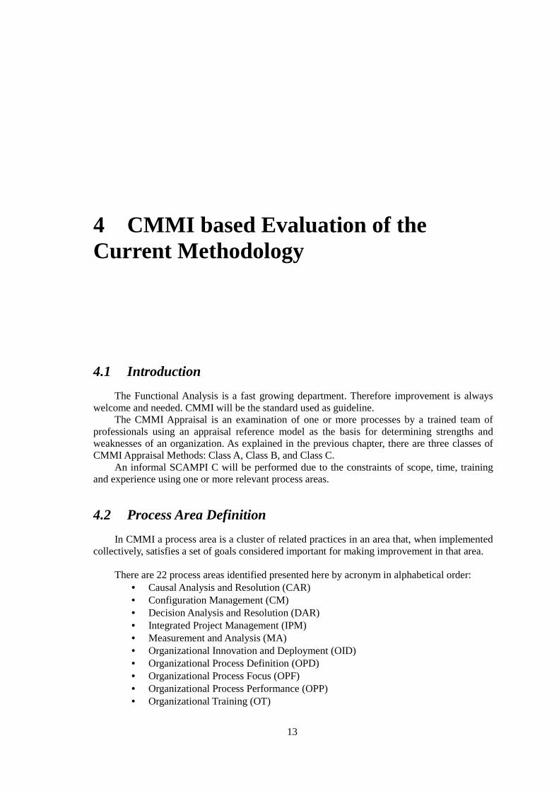
Figure 9: CMMI Model Components.
Generic goals are called “generic” because the same goal statement applies to multiple process areas. A generic goal describes the characteristics that must be present to institutionalize the processes that implement a process area.
A generic practice is the description of an activity that is considered important in achieving the associated generic goal.
The analysis should include all the required and expected model components mapped against the workflows and templates used. Therefore, within this dissertation, every specific goal will be evaluated by its associated specific practices. Each specific practice will be measured by their typical work products and subpractices.
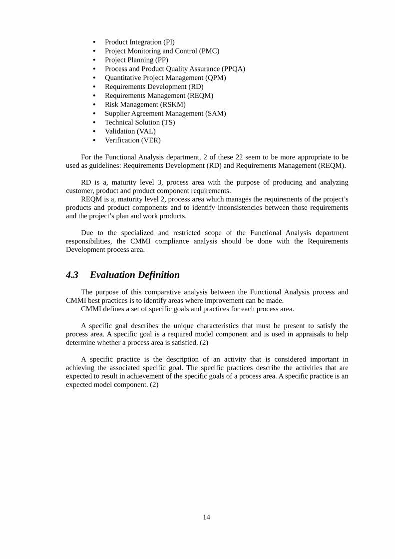
The rating for each model component will be the following:
Specific Practices Ratings Typical Work Products and SubPractices Ratings
Out of the Scope Not Rated
Not Characterized Unsatisfied
Not Implemented Satisfied
Partially Implemented
Largely Implemented
Fully Implemented
Figure 10: Analysis Ratings.
This evaluation is performed at low-level CMMI model components. Only the specific
practices will be rated, along with the typical work products and subpractices. The ratings won’t be used for specific goals.
The specific practices rating is based on SCAMPI, which means that a specific scale for each rate is used:
• Not Implemented represents from 0 to 15% • Partially Implemented represents from >15% to 50% • Largely Implemented represents from >50% to 85% • Fully Implemented represents from >85% to 100%
The typical work products and subpractices rating is based on a simple binary scale (satisfied, unsatisfied) considering the possibility of some fuzzy situations (not rated).
Process Area
Generic PracticesGeneric Practices
Generic GoalsGeneric Goals
Expected InformativeInformativeRequiredKEY:
Purpose Statement
IntroductoryNotes
RelatedProcess Areas
SubpracticesSubpractices
Specific GoalsSpecific Goals
Specific PracticesSpecific Practices
Typical WorkProducts
Typical WorkProducts
SubpracticesSubpractices SubpracticesGeneric Practice Elaborations
16
4.4 Evaluation Matrix
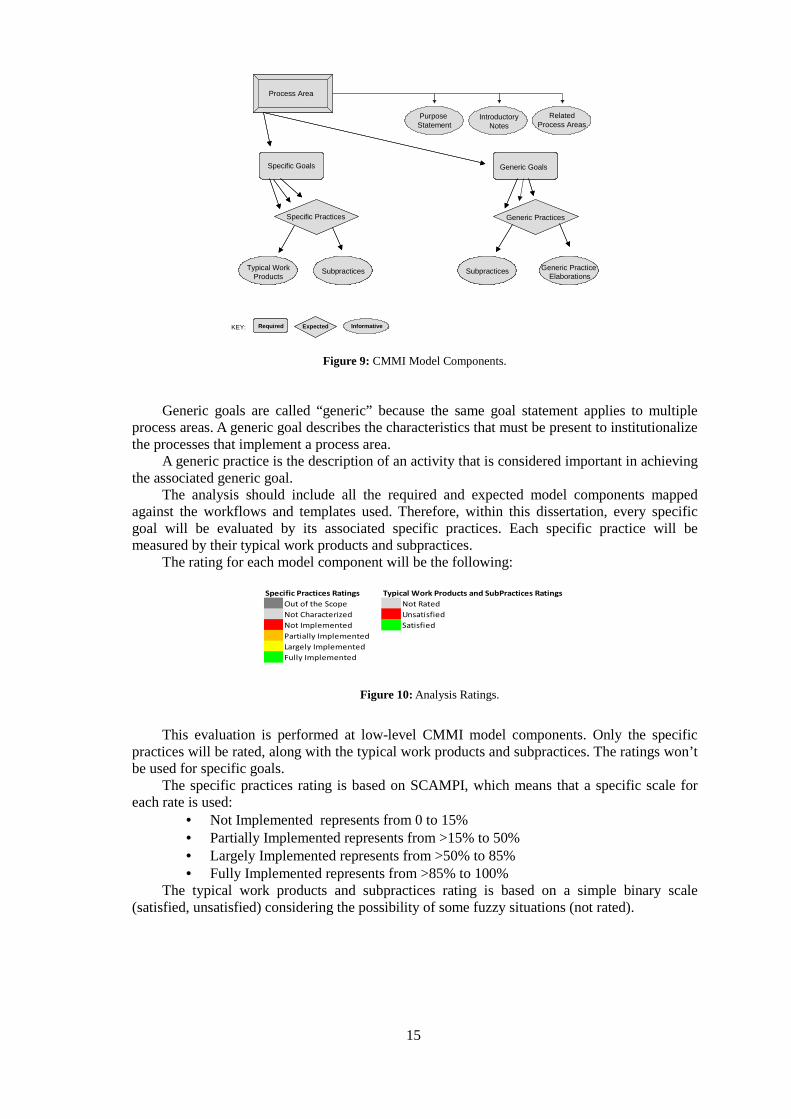
The current Functional Analysis methodology will be evaluated through a matrix, showing both stages and the set of specific goals, practices, typical work products and subpractices required.
Requirements DevelopmentAn Engineering Process Area at Maturity Level 3
Typ
ical W
ork
Pro
du
cts
Su
bP
racti
ces
SG 1 Develop Customer Requirements
SP 1.1 Elicit Stakeholder Needs 1 1
SP 1.2 Develop and Prioritize Customer Requirements 3 3
SG 2 Develop Product Requirements
SP 2.1 Establish Product and Product Component Requirements 3 3
SP 2.2 Allocate Product Component Requirements 5 4
SP 2.3 Identify Interface Requirements 1 2
SG 3 Analyze and Validate Requirements
SP 3.1 Establish Operational Concepts and Scenarios 6 4
SP 3.2 Establish a Definition of Required Functionality 3 6
SP 3.3 Analyze Requirements 4 6
SP 3.4 Analyze Requirements to Achieve Balance 1 3
SP 3.5 Validate Requirements 1 3
28 35
Figure 11: Requirements Development Subcomponent count .
Requirements Development (RD) clusters 3 specific goals, with a total of 10 specific practices, 28 typical work products and 35 subpractices.
4.5 CMMI Compliance Analysis of the Current Methodology
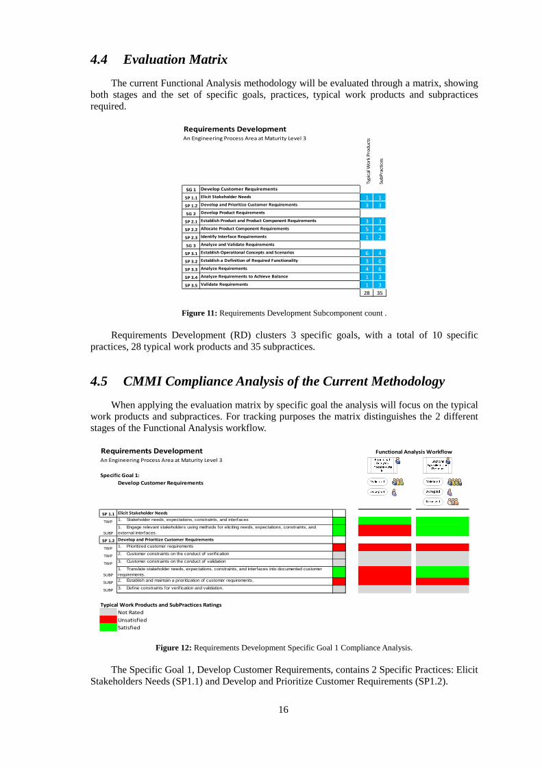
When applying the evaluation matrix by specific goal the analysis will focus on the typical work products and subpractices. For tracking purposes the matrix distinguishes the 2 different stages of the Functional Analysis workflow.
Requirements DevelopmentAn Engineering Process Area at Maturity Level 3
Specific Goal 1:
Develop Customer Requirements
SP 1.1 Elicit Stakeholder Needs
TWP1. Stakeholder needs, expectations, constraints, and interfaces
SUBP
1. Engage relevant stakeholders using methods for eliciting needs, expectations, constraints, and external interfaces.
SP 1.2 Develop and Prioritize Customer Requirements
TWP1. Prioritized customer requirements
TWP2. Customer constraints on the conduct of verif ication
TWP3. Customer constraints on the conduct of validation
SUBP
1. Translate stakeholder needs, expectations, constraints, and interfaces into documented customer requirements.
SUBP2. Establish and maintain a prioritization of customer requirements.
SUBP3. Define constraints for verif ication and validation.
Typical Work Products and SubPractices Ratings
Not Rated
Unsatisfied
Satisfied
Functional Analysis Workflow
Figure 12: Requirements Development Specific Goal 1 Compliance Analysis.
The Specific Goal 1, Develop Customer Requirements, contains 2 Specific Practices: Elicit Stakeholders Needs (SP1.1) and Develop and Prioritize Customer Requirements (SP1.2).
17
The SP1.1 states: “Eliciting goes beyond collecting requirements by proactively
identifying additional requirements not explicitly provided by customers. Additional requirements should address the various product lifecycle activities and their impact on the product” (2). During the current Functional Analysis stage, the stakeholders’ constraints and interfaces are documented. But only during the current Functional Specification stage will the professional, sometimes with the customer, detect some additional requirements coming from the product implementation.
The SP1.2 states: “The various inputs from the relevant stakeholders must be consolidated,
missing information must be obtained, and conflicts must be resolved in documenting the recognized set of customer requirements. The customer requirements may include needs, expectations, and constraints with regard to verification and validation” (2). The Functional Specifications document will identify the customer’s needs and expectations along with the interfaces needs.
Requirements DevelopmentAn Engineering Process Area at Maturity Level 3
Specific Goal 2:
Develop Product Requirements
SP 2.1 Establish Product and Product Component Requirements
TWP1. Derived requirements
TWP2. Product requirements
TWP3. Product component requirements
SUBP
1. Develop requirements in technical terms necessary for product andproduct component design.
SUBP2. Derive requirements that result from design decisions.
SUBP
3. Establish and maintain relationships betw een requirements forconsideration during change management and requirementsallocation.
SP 2.2 Allocate Product Component Requirements
TWP1. Requirement allocation sheets
TWP2. Provisional requirement allocations
TWP3. Design constraints
TWP4. Derived requirements
TWP5. Relationships among derived requirements
SUBP1. Allocate requirements to functions.
SUBP2. Allocate requirements to product components.
SUBP3. Allocate design constraints to product components.
SUBP4. Document relationships among allocated requirements.
SP 2.3 Identify Interface Requirements
TWP1. Interface requirements
SUBP
1. Identify interfaces both external to the product and internal to the product (i.e., betw een functional partitions or objects).
SUBP2. Develop the requirements for the identif ied interfaces.
Typical Work Products and SubPractices Ratings
Not Rated
Unsatisfied
Satisfied
Functional Analysis Workflow
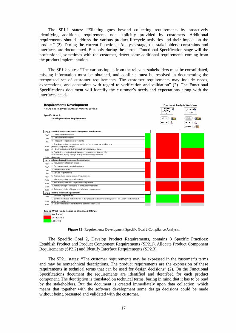
Figure 13: Requirements Development Specific Goal 2 Compliance Analysis.
The Specific Goal 2, Develop Product Requirements, contains 3 Specific Practices: Establish Product and Product Component Requirements (SP2.1), Allocate Product Component Requirements (SP2.2) and Identify Interface Requirements (SP2.3).
The SP2.1 states: “The customer requirements may be expressed in the customer’s terms
and may be nontechnical descriptions. The product requirements are the expression of these requirements in technical terms that can be used for design decisions” (2). On the Functional Specifications document the requirements are identified and described for each product component. The description is translated on technical terms, baring in mind that it has to be read by the stakeholders. But the document is created immediately upon data collection, which means that together with the software development some design decisions could be made without being presented and validated with the customer.
18
The SP2.2 states: “The requirements for product components of the defined solution
include allocation of product performance; design constraints; and fit, form, and function to meet requirements and facilitate production. In cases where a higher level requirement specifies performance that will be the responsibility of two or more product components, the performance must be partitioned for unique allocation to each product component as a derived requirement” (2). This specific practice is not satisfied due to the early stage of the documentation and the lack of change management within the process. The templates used are high level requirements documentations, so they cannot allocate specific requirements to functions.
The SP2.3 states:”Interfaces between functions (or between objects) are identified.
Functional interfaces may drive the development of alternative solutions described in the Technical Solution process area” (2). As previously described the templates used are high level, so additional solutions found from interfaces will not occur.
19
Requirements DevelopmentAn Engineering Process Area at Maturity Level 3
Specific Goal 3:
Analyze and Validate Requirements
SP 3.1 Establish Operational Concepts and Scenarios
TWP1. Operational concept
TWP2. Product or product component installation, operational, maintenance, and support concepts
TWP3. Disposal concepts
TWP4. Use cases
TWP5. Timeline scenarios
TWP6. New requirements
SUBP
1. Develop operational concepts and scenarios that include functionality, performance, maintenance, support, and disposal as appropriate.
SUBP
2. Def ine the environment in w hich the product or product component w ill operate, including boundaries and constraints.
SUBP3. Review operational concepts and scenarios to ref ine and discover requirements.
SUBP
4. Develop a detailed operational concept, as products and product components are selected, that defines the interaction of the product, the end user, and the environment, and that satisfies the operational, maintenance, support, and disposal needs.
SP 3.2 Establish a Definition of Required Functionality
TWP1. Functional architecture
TWP2. Activity diagrams and use cases
TWP3. Object-oriented analysis w ith services or methods identif ied
SUBP1. Analyze and quantify functionality required by end users.
SUBP2. Analyze requirements to identify logical or functional partitions
SUBP3. Partition requirements into groups, based on established criteria
SUBP
4. Consider the sequencing of time-critical functions both initially and subsequently during product component development.
SUBP
5. Allocate customer requirements to functional partitions, objects, people, or support elements to support the synthesis of solutions.
SUBP6. Allocate functional and performance requirements to functions and subfunctions.
SP 3.3 Analyze Requirements
TWP1. Requirements defects reports
TWP2. Proposed requirements changes to resolve defects
TWP3. Key requirements
TWP4. Technical performance measures
SUBP
1. Analyze stakeholder needs, expectations, constraints, and external interfaces to remove conflicts and to organize into related subjects.
SUBP2. Analyze requirements to determine w hether they satisfy the objectives of higher level requirements.
SUBP3. Analyze requirements to ensure that they are complete, feasible, realizable, and verif iable.
SUBP
4. Identify key requirements that have a strong influence on cost, schedule, functionality, risk, or performance.
SUBP5. Identify technical performance measures that w ill be tracked during the development effort.
SUBP
6. Analyze operational concepts and scenarios to refine the customer needs, constraints, and interfaces and to discover new requirements.
SP 3.4 Analyze Requirements to Achieve Balance
TWP1. Assessment of risks related to requirements
SUBP
1. Use proven models, simulations, and prototyping to analyze the balance of stakeholder needs and constraints.
SUBP2. Perform a risk assessment on the requirements and functional architecture.
SUBP3. Examine product lifecycle concepts for impacts of requirements on risks.
SP 3.5 Validate Requirements
TWP1. Record of analysis methods and results
SUBP
1. Analyze the requirements to determine the risk that the resulting product w ill not perform appropriately in its intended-use environment.
SUBP
2. Explore the adequacy and completeness of requirements by developing product representations (e.g., prototypes, simulations, models, scenarios, and storyboards) and by obtaining feedback about them from relevant stakeholders.
SUBP
3. Assess the design as it matures in the context of the requirements validation environment to identify validation issues and expose unstated needs and customer requirements.
Typical Work Products and SubPractices Ratings
Not Rated
Unsatisfied
Satisfied
Functional Analysis Workflow
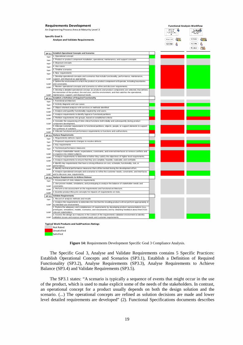
Figure 14: Requirements Development Specific Goal 3 Compliance Analysis.
The Specific Goal 3, Analyse and Validate Requirements contains 5 Specific Practices: Establish Operational Concepts and Scenarios (SP3.1), Establish a Definition of Required Functionality (SP3.2), Analyse Requirements (SP3.3), Analyse Requirements to Achieve Balance (SP3.4) and Validate Requirements (SP3.5).
The SP3.1 states: “A scenario is typically a sequence of events that might occur in the use
of the product, which is used to make explicit some of the needs of the stakeholders. In contrast, an operational concept for a product usually depends on both the design solution and the scenario. (...) The operational concepts are refined as solution decisions are made and lower level detailed requirements are developed” (2). Functional Specifications documents describes
20
in detail how the stakeholders will interact with the product and with the product components. But it is out of the scope of this department the product installation, maintenance and support.
The SP3.2 states: “The definition of functionality can include actions, sequence, inputs,
outputs, or other information that communicates the manner in which the product will be used” (2).
The workflows presented on the documents are UML behaviour diagrams, so the interaction with the product is described in detail. The representation of functional architecture diagrams and low-level detailed documents stating object-oriented analysis is out of the scope.
The SP3.3 states: “As requirements are defined, their relationship to higher level
requirements and the higher level defined functionality must be understood. One of the other actions is the determination of which key requirements will be used to track progress. For instance, the weight of a product or size of a software product may be monitored through development based on its risk” (2). A number of conditions minimizes the implementation potential of this specific practice: the requirements are not prioritized and a lot of typical work products and subpractices are out of the scope of this department.
The SP3.4 states: “Stakeholder needs and constraints can address cost, schedule,
performance, functionality, reusable components, maintainability, or risk” (2). As it happened previously this specific practice is completely out of the scope of this department.
The SP3.5 states: “Requirements validation is performed early in the development effort
with end users to gain confidence that the requirements are capable of guiding a development that results in successful final validation. This activity should be integrated with risk management activities” (2). Once again this specific practice is completely out of the scope of this department, although informally the Functional Analysts keeps track of the customer requirements during the Functional and Technical Architecture stages, along with the Interface Design team.
21
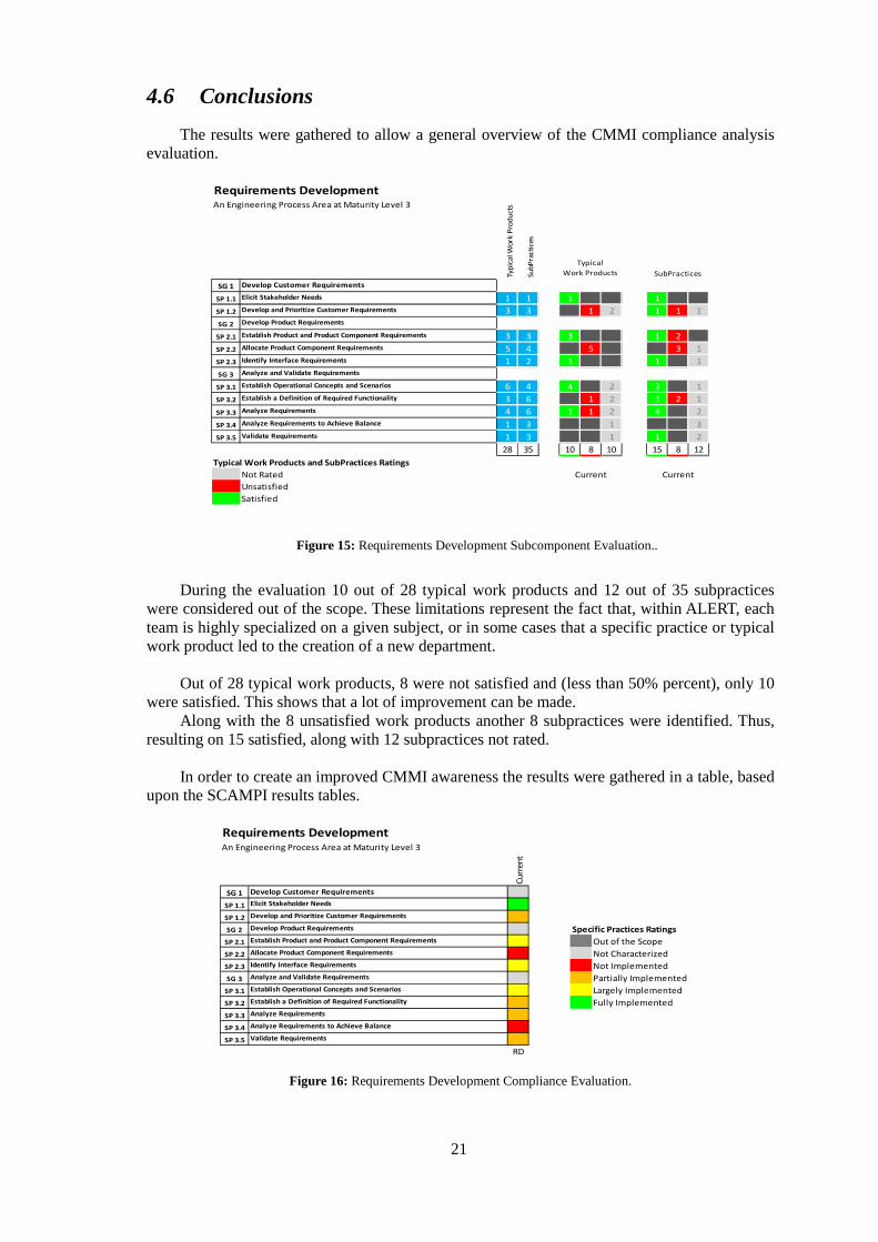
4.6 Conclusions
The results were gathered to allow a general overview of the CMMI compliance analysis evaluation.
Requirements DevelopmentAn Engineering Process Area at Maturity Level 3
Typ
ical W
ork
Pro
du
cts
Su
bP
racti
ces
SG 1 Develop Customer Requirements
SP 1.1 Elicit Stakeholder Needs 1 1 1 1
SP 1.2 Develop and Prioritize Customer Requirements 3 3 1 2 1 1 1
SG 2 Develop Product Requirements
SP 2.1 Establish Product and Product Component Requirements 3 3 3 1 2
SP 2.2 Allocate Product Component Requirements 5 4 5 3 1
SP 2.3 Identify Interface Requirements 1 2 1 1 1
SG 3 Analyze and Validate Requirements
SP 3.1 Establish Operational Concepts and Scenarios 6 4 4 2 3 1
SP 3.2 Establish a Definition of Required Functionality 3 6 1 2 3 2 1
SP 3.3 Analyze Requirements 4 6 1 1 2 4 2
SP 3.4 Analyze Requirements to Achieve Balance 1 3 1 3
SP 3.5 Validate Requirements 1 3 1 1 2
28 35 10 8 10 15 8 12
Typical Work Products and SubPractices Ratings
Not Rated Current Current
Unsatisfied
Satisfied
Typical
Work Products SubPractices
Figure 15: Requirements Development Subcomponent Evaluation..
During the evaluation 10 out of 28 typical work products and 12 out of 35 subpractices
were considered out of the scope. These limitations represent the fact that, within ALERT, each team is highly specialized on a given subject, or in some cases that a specific practice or typical work product led to the creation of a new department.
Out of 28 typical work products, 8 were not satisfied and (less than 50% percent), only 10
were satisfied. This shows that a lot of improvement can be made. Along with the 8 unsatisfied work products another 8 subpractices were identified. Thus,
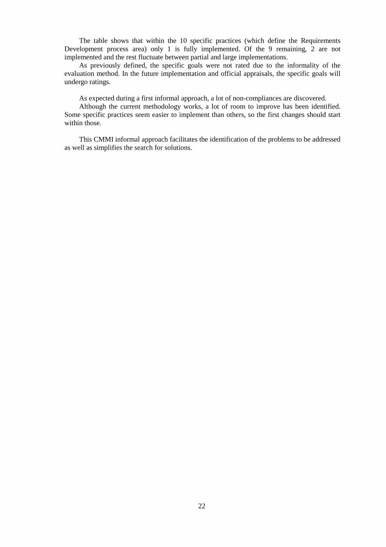
resulting on 15 satisfied, along with 12 subpractices not rated. In order to create an improved CMMI awareness the results were gathered in a table, based
upon the SCAMPI results tables.
Requirements DevelopmentAn Engineering Process Area at Maturity Level 3
Cu
rren
t
SG 1 Develop Customer Requirements
SP 1.1 Elicit Stakeholder Needs
SP 1.2 Develop and Prioritize Customer Requirements
SG 2 Develop Product Requirements Specific Practices Ratings
SP 2.1 Establish Product and Product Component Requirements Out of the Scope
SP 2.2 Allocate Product Component Requirements Not Characterized
SP 2.3 Identify Interface Requirements Not Implemented
SG 3 Analyze and Validate Requirements Partially Implemented
SP 3.1 Establish Operational Concepts and Scenarios Largely Implemented
SP 3.2 Establish a Definition of Required Functionality Fully Implemented
SP 3.3 Analyze Requirements
SP 3.4 Analyze Requirements to Achieve Balance
SP 3.5 Validate Requirements
RD
Figure 16: Requirements Development Compliance Evaluation.
22
The table shows that within the 10 specific practices (which define the Requirements Development process area) only 1 is fully implemented. Of the 9 remaining, 2 are not implemented and the rest fluctuate between partial and large implementations.
As previously defined, the specific goals were not rated due to the informality of the evaluation method. In the future implementation and official appraisals, the specific goals will undergo ratings.
As expected during a first informal approach, a lot of non-compliances are discovered. Although the current methodology works, a lot of room to improve has been identified.
Some specific practices seem easier to implement than others, so the first changes should start within those.
This CMMI informal approach facilitates the identification of the problems to be addressed
as well as simplifies the search for solutions.
23
5 Proposed Requirements Development Methodology
5.1 Functional Analysis Workflow
The CMMI compliance analysis shows that the workflow currently used needs some changes.
Two additional teams were created during the implementation of the changes:
• Gap Analysis; • Release Planning.
The Gap Analysis team, aids in the creation of the workflows, which represents the future implementation of the product onsite. This team also validates the customer requirements detected to prevent needs which could be solved without further product development.
The Release Planning team receives all the requirements from the different customers and markets prioritizing all of them according to: feedback from the product managers about the time/work needed for requirement, the administration strategy and the sales team commitments. This requirements prioritization will translate in the definition of when each one of it will be developed.
Some of the specific practices with the least implementation were related to the
prioritization of requirements along with the discovery of additional requirements, within the development process.
An approach to these problems could be done, introducing the concept of customer
requirements and product requirements stated on CMMI. The customer requirements would be defined and agreed with the customer. The product requirements will be the solution(s) to a specific customer requirement.
24
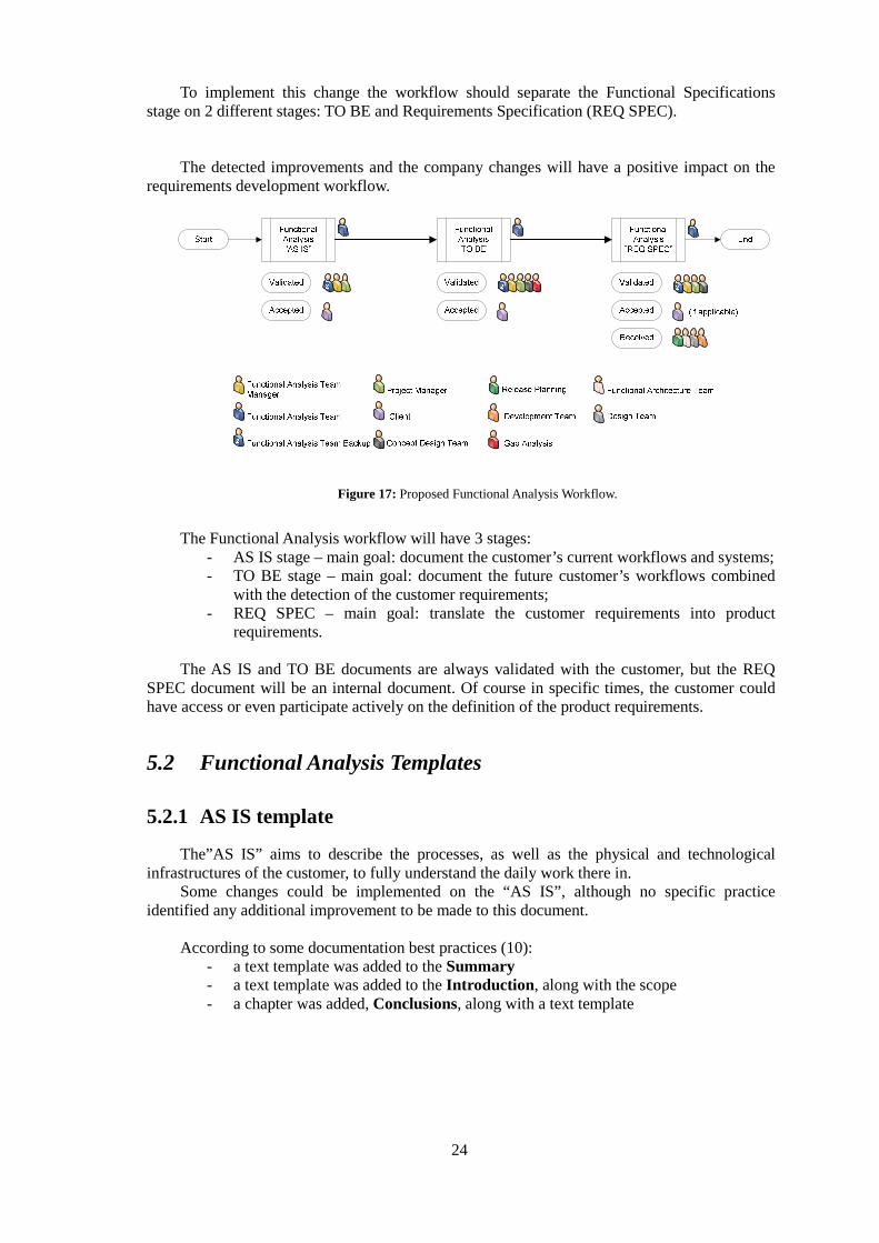
To implement this change the workflow should separate the Functional Specifications stage on 2 different stages: TO BE and Requirements Specification (REQ SPEC).
The detected improvements and the company changes will have a positive impact on the requirements development workflow.
Figure 17: Proposed Functional Analysis Workflow.
The Functional Analysis workflow will have 3 stages:
- AS IS stage – main goal: document the customer’s current workflows and systems; - TO BE stage – main goal: document the future customer’s workflows combined
with the detection of the customer requirements; - REQ SPEC – main goal: translate the customer requirements into product
requirements. The AS IS and TO BE documents are always validated with the customer, but the REQ
SPEC document will be an internal document. Of course in specific times, the customer could have access or even participate actively on the definition of the product requirements.
5.2 Functional Analysis Templates
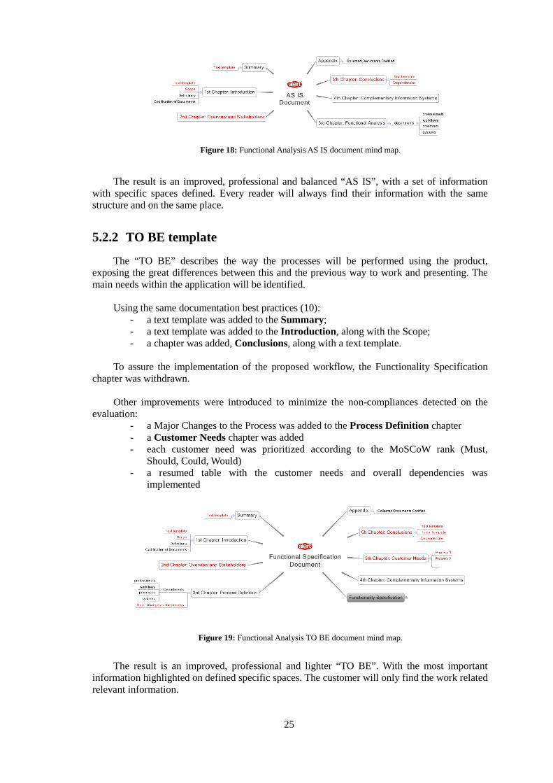
5.2.1 AS IS template
The”AS IS” aims to describe the processes, as well as the physical and technological infrastructures of the customer, to fully understand the daily work there in.
Some changes could be implemented on the “AS IS”, although no specific practice identified any additional improvement to be made to this document.
According to some documentation best practices (10): - a text template was added to the Summary - a text template was added to the Introduction, along with the scope - a chapter was added, Conclusions, along with a text template
25
Figure 18: Functional Analysis AS IS document mind map.
The result is an improved, professional and balanced “AS IS”, with a set of information with specific spaces defined. Every reader will always find their information with the same structure and on the same place.
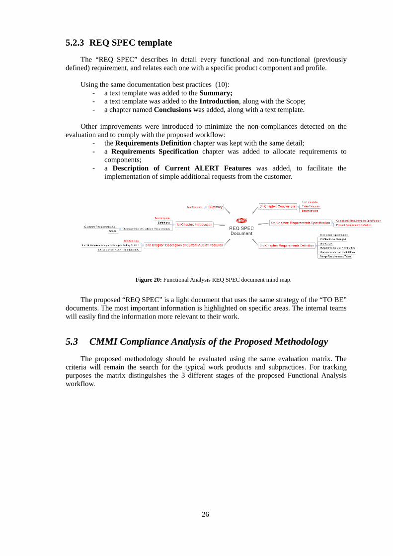
5.2.2 TO BE template
The “TO BE” describes the way the processes will be performed using the product, exposing the great differences between this and the previous way to work and presenting. The main needs within the application will be identified.
Using the same documentation best practices (10):
- a text template was added to the Summary; - a text template was added to the Introduction, along with the Scope; - a chapter was added, Conclusions, along with a text template.
To assure the implementation of the proposed workflow, the Functionality Specification
chapter was withdrawn.
Other improvements were introduced to minimize the non-compliances detected on the evaluation:
- a Major Changes to the Process was added to the Process Definition chapter - a Customer Needs chapter was added - each customer need was prioritized according to the MoSCoW rank (Must,
Should, Could, Would) - a resumed table with the customer needs and overall dependencies was
implemented
Figure 19: Functional Analysis TO BE document mind map.
The result is an improved, professional and lighter “TO BE”. With the most important
information highlighted on defined specific spaces. The customer will only find the work related relevant information.
26
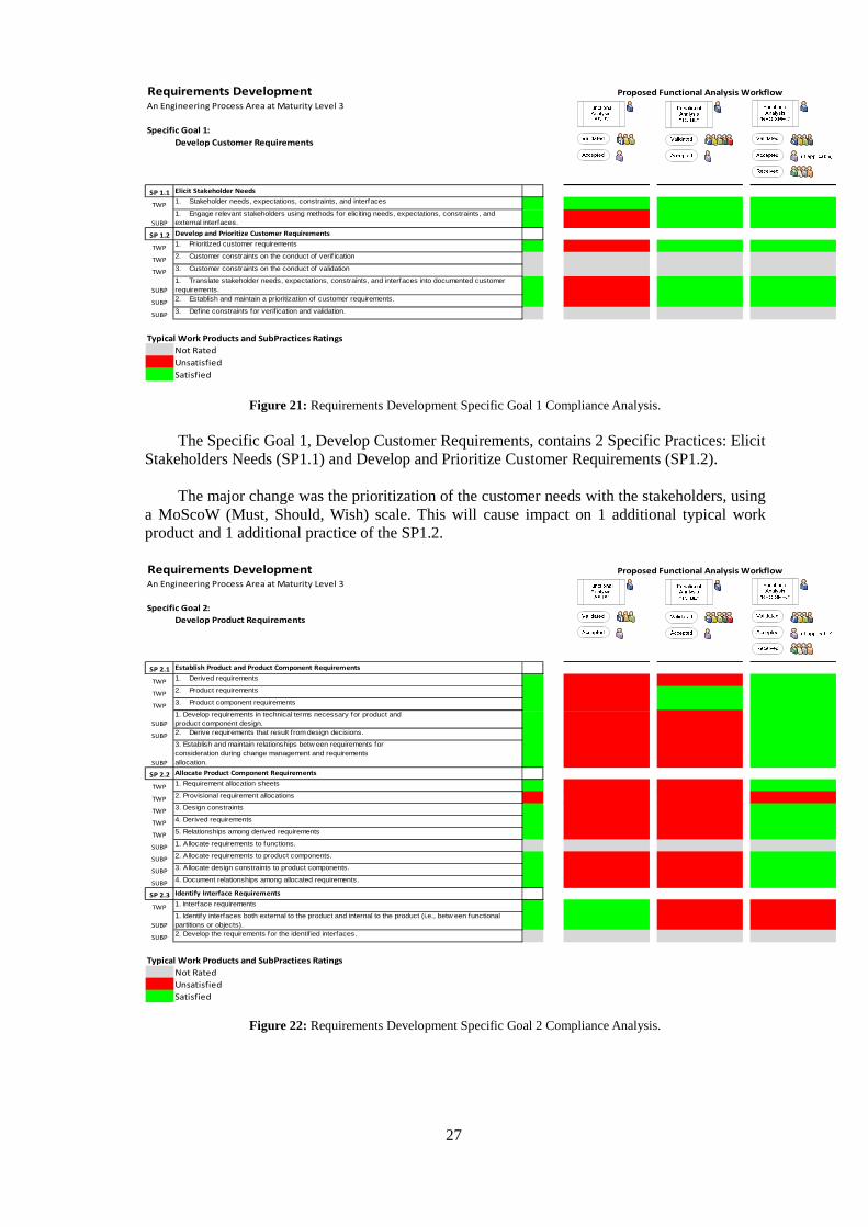
5.2.3 REQ SPEC template
The “REQ SPEC” describes in detail every functional and non-functional (previously defined) requirement, and relates each one with a specific product component and profile.
Using the same documentation best practices (10):
- a text template was added to the Summary; - a text template was added to the Introduction, along with the Scope; - a chapter named Conclusions was added, along with a text template.
Other improvements were introduced to minimize the non-compliances detected on the
evaluation and to comply with the proposed workflow: - the Requirements Definition chapter was kept with the same detail; - a Requirements Specification chapter was added to allocate requirements to
components; - a Description of Current ALERT Features was added, to facilitate the
implementation of simple additional requests from the customer.
Figure 20: Functional Analysis REQ SPEC document mind map.
The proposed “REQ SPEC” is a light document that uses the same strategy of the “TO BE”
documents. The most important information is highlighted on specific areas. The internal teams will easily find the information more relevant to their work.
5.3 CMMI Compliance Analysis of the Proposed Methodology
The proposed methodology should be evaluated using the same evaluation matrix. The criteria will remain the search for the typical work products and subpractices. For tracking purposes the matrix distinguishes the 3 different stages of the proposed Functional Analysis workflow.
27
Requirements DevelopmentAn Engineering Process Area at Maturity Level 3
Specific Goal 1:
Develop Customer Requirements
SP 1.1 Elicit Stakeholder Needs
TWP1. Stakeholder needs, expectations, constraints, and interfaces
SUBP
1. Engage relevant stakeholders using methods for eliciting needs, expectations, constraints, and external interfaces.
SP 1.2 Develop and Prioritize Customer Requirements
TWP1. Prioritized customer requirements
TWP2. Customer constraints on the conduct of verif ication
TWP3. Customer constraints on the conduct of validation
SUBP
1. Translate stakeholder needs, expectations, constraints, and interfaces into documented customer requirements.
SUBP2. Establish and maintain a prioritization of customer requirements.
SUBP3. Define constraints for verif ication and validation.
Typical Work Products and SubPractices Ratings
Not Rated
Unsatisfied
Satisfied
Proposed Functional Analysis Workflow
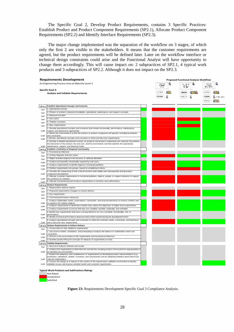
Figure 21: Requirements Development Specific Goal 1 Compliance Analysis.
The Specific Goal 1, Develop Customer Requirements, contains 2 Specific Practices: Elicit
Stakeholders Needs (SP1.1) and Develop and Prioritize Customer Requirements (SP1.2). The major change was the prioritization of the customer needs with the stakeholders, using
a MoScoW (Must, Should, Wish) scale. This will cause impact on 1 additional typical work product and 1 additional practice of the SP1.2. Requirements DevelopmentAn Engineering Process Area at Maturity Level 3
Specific Goal 2:
Develop Product Requirements
SP 2.1 Establish Product and Product Component Requirements
TWP1. Derived requirements
TWP2. Product requirements
TWP3. Product component requirements
SUBP
1. Develop requirements in technical terms necessary for product andproduct component design.
SUBP2. Derive requirements that result from design decisions.
SUBP
3. Establish and maintain relationships betw een requirements forconsideration during change management and requirementsallocation.
SP 2.2 Allocate Product Component Requirements
TWP1. Requirement allocation sheets
TWP2. Provisional requirement allocations
TWP3. Design constraints
TWP4. Derived requirements
TWP5. Relationships among derived requirements
SUBP1. Allocate requirements to functions.
SUBP2. Allocate requirements to product components.
SUBP3. Allocate design constraints to product components.
SUBP4. Document relationships among allocated requirements.
SP 2.3 Identify Interface Requirements
TWP1. Interface requirements
SUBP
1. Identify interfaces both external to the product and internal to the product (i.e., betw een functional partitions or objects).
SUBP2. Develop the requirements for the identif ied interfaces.
Typical Work Products and SubPractices Ratings
Not Rated
Unsatisfied
Satisfied
Proposed Functional Analysis Workflow
Figure 22: Requirements Development Specific Goal 2 Compliance Analysis.
28
The Specific Goal 2, Develop Product Requirements, contains 3 Specific Practices: Establish Product and Product Component Requirements (SP2.1), Allocate Product Component Requirements (SP2.2) and Identify Interface Requirements (SP2.3).
The major change implemented was the separation of the workflow on 3 stages, of which
only the first 2 are visible to the stakeholders. It means that the customer requirements are agreed, but the product requirements will be defined later. Later on the workflow interface or technical design constraints could arise and the Functional Analyst will have opportunity to change them accordingly. This will cause impact on: 2 subpractices of SP2.1, 4 typical work products and 3 subpractices of SP2.2. Although it does not impact on the SP2.3. Requirements DevelopmentAn Engineering Process Area at Maturity Level 3
Specific Goal 3:
Analyze and Validate Requirements
SP 3.1 Establish Operational Concepts and Scenarios
TWP1. Operational concept
TWP2. Product or product component installation, operational, maintenance, and support concepts
TWP3. Disposal concepts
TWP4. Use cases
TWP5. Timeline scenarios
TWP6. New requirements
SUBP
1. Develop operational concepts and scenarios that include functionality, performance, maintenance, support, and disposal as appropriate.
SUBP
2. Def ine the environment in w hich the product or product component w ill operate, including boundaries and constraints.
SUBP3. Review operational concepts and scenarios to ref ine and discover requirements.
SUBP
4. Develop a detailed operational concept, as products and product components are selected, that defines the interaction of the product, the end user, and the environment, and that satisf ies the operational, maintenance, support, and disposal needs.
SP 3.2 Establish a Definition of Required Functionality
TWP1. Functional architecture
TWP2. Activity diagrams and use cases
TWP3. Object-oriented analysis w ith services or methods identif ied
SUBP1. Analyze and quantify functionality required by end users.
SUBP2. Analyze requirements to identify logical or functional partitions
SUBP3. Partition requirements into groups, based on established criteria
SUBP
4. Consider the sequencing of time-critical functions both initially and subsequently during product component development.
SUBP
5. Allocate customer requirements to functional partitions, objects, people, or support elements to support the synthesis of solutions.
SUBP6. Allocate functional and performance requirements to functions and subfunctions.
SP 3.3 Analyze Requirements
TWP1. Requirements defects reports
TWP2. Proposed requirements changes to resolve defects
TWP3. Key requirements
TWP4. Technical performance measures
SUBP
1. Analyze stakeholder needs, expectations, constraints, and external interfaces to remove conflicts and to organize into related subjects.
SUBP2. Analyze requirements to determine w hether they satisfy the objectives of higher level requirements.
SUBP3. Analyze requirements to ensure that they are complete, feasible, realizable, and verif iable.
SUBP
4. Identify key requirements that have a strong influence on cost, schedule, functionality, risk, or performance.
SUBP5. Identify technical performance measures that w ill be tracked during the development effort.
SUBP
6. Analyze operational concepts and scenarios to refine the customer needs, constraints, and interfaces and to discover new requirements.
SP 3.4 Analyze Requirements to Achieve Balance
TWP1. Assessment of risks related to requirements
SUBP
1. Use proven models, simulations, and prototyping to analyze the balance of stakeholder needs and constraints.
SUBP2. Perform a risk assessment on the requirements and functional architecture.
SUBP3. Examine product lifecycle concepts for impacts of requirements on risks.
SP 3.5 Validate Requirements
TWP1. Record of analysis methods and results
SUBP
1. Analyze the requirements to determine the risk that the resulting product w ill not perform appropriately in its intended-use environment.
SUBP
2. Explore the adequacy and completeness of requirements by developing product representations (e.g., prototypes, simulations, models, scenarios, and storyboards) and by obtaining feedback about them from relevant stakeholders.
SUBP
3. Assess the design as it matures in the context of the requirements validation environment to identify validation issues and expose unstated needs and customer requirements.
Typical Work Products and SubPractices Ratings
Not Rated
Unsatisfied
Satisfied
Proposed Functional Analysis Workflow
Figure 23: Requirements Development Specific Goal 3 Compliance Analysis.
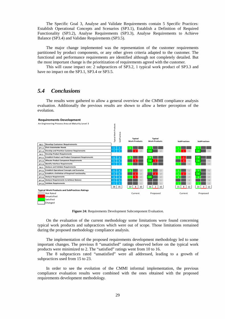
29
The Specific Goal 3, Analyse and Validate Requirements contain 5 Specific Practices: Establish Operational Concepts and Scenarios (SP3.1), Establish a Definition of Required Functionality (SP3.2), Analyse Requirements (SP3.3), Analyse Requirements to Achieve Balance (SP3.4) and Validate Requirements (SP3.5).
The major change implemented was the representation of the customer requirements
partitioned by product components, or any other given criteria adapted to the customer. The functional and performance requirements are identified although not completely detailed. But the most important change is the prioritization of requirements agreed with the customer.
This will cause impact on: 2 subpractices of SP3.2, 1 typical work product of SP3.3 and have no impact on the SP3.1, SP3.4 or SP3.5.
5.4 Conclusions
The results were gathered to allow a general overview of the CMMI compliance analysis evaluation. Additionally the previous results are shown to allow a better perception of the evolution. Requirements DevelopmentAn Engineering Process Area at Maturity Level 3
Typ
ical W
ork
Pro
du
cts
Su
bP
racti
ces
SG 1 Develop Customer Requirements
SP 1.1 Elicit Stakeholder Needs 1 1 1 1 1 1
SP 1.2 Develop and Prioritize Customer Requirements 3 3 1 2 1 2 1 1 1 2 1
SG 2 Develop Product Requirements
SP 2.1 Establish Product and Product Component Requirements 3 3 3 3 1 2 3
SP 2.2 Allocate Product Component Requirements 5 4 5 4 1 3 1 3 1
SP 2.3 Identify Interface Requirements 1 2 1 1 1 1 1 1
SG 3 Analyze and Validate Requirements
SP 3.1 Establish Operational Concepts and Scenarios 6 4 4 2 4 2 3 1 3 1
SP 3.2 Establish a Definition of Required Functionality 3 6 1 2 1 2 3 2 1 5 1
SP 3.3 Analyze Requirements 4 6 1 1 2 2 2 4 2 4 2
SP 3.4 Analyze Requirements to Achieve Balance 1 3 1 1 3 3
SP 3.5 Validate Requirements 1 3 1 1 1 2 1 2
28 35 10 8 10 16 2 10 15 8 12 23 0 12
Typical Work Products and SubPractices Ratings
Not Rated Current Proposed Current Proposed
Unsatisfied
Satisfied
Changed
SubPractices
Typical
Work Products SubPractices
Typical
Work Products
Figure 24: Requirements Development Subcomponent Evaluation.
On the evaluation of the current methodology some limitations were found concerning
typical work products and subpractices which were out of scope. Those limitations remained during the proposed methodology compliance analysis.
The implementation of the proposed requirements development methodology led to some
important changes. The previous 8 “unsatisfied” ratings observed before on the typical work products were minimized to 2. The “satisfied” ratings went from 10 to 16.
The 8 subpractices rated “unsatisfied” were all addressed, leading to a growth of subpractices used from 15 to 23.
In order to see the evolution of the CMMI informal implementation, the previous
compliance evaluation results were combined with the ones obtained with the proposed requirements development methodology.
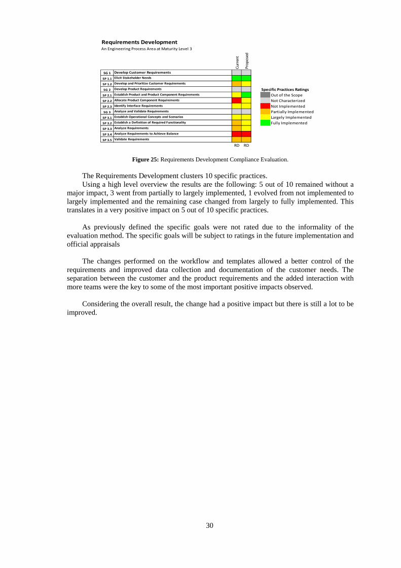
30
Requirements DevelopmentAn Engineering Process Area at Maturity Level 3
Cu
rren
t
Pro
po
sed
SG 1 Develop Customer Requirements
SP 1.1 Elicit Stakeholder Needs
SP 1.2 Develop and Prioritize Customer Requirements
SG 2 Develop Product Requirements Specific Practices Ratings
SP 2.1 Establish Product and Product Component Requirements Out of the Scope
SP 2.2 Allocate Product Component Requirements Not Characterized
SP 2.3 Identify Interface Requirements Not Implemented
SG 3 Analyze and Validate Requirements Partially Implemented
SP 3.1 Establish Operational Concepts and Scenarios Largely Implemented
SP 3.2 Establish a Definition of Required Functionality Fully Implemented
SP 3.3 Analyze Requirements
SP 3.4 Analyze Requirements to Achieve Balance
SP 3.5 Validate Requirements
RD RD
Figure 25: Requirements Development Compliance Evaluation.
The Requirements Development clusters 10 specific practices. Using a high level overview the results are the following: 5 out of 10 remained without a
major impact, 3 went from partially to largely implemented, 1 evolved from not implemented to largely implemented and the remaining case changed from largely to fully implemented. This translates in a very positive impact on 5 out of 10 specific practices.
As previously defined the specific goals were not rated due to the informality of the
evaluation method. The specific goals will be subject to ratings in the future implementation and official appraisals
The changes performed on the workflow and templates allowed a better control of the
requirements and improved data collection and documentation of the customer needs. The separation between the customer and the product requirements and the added interaction with more teams were the key to some of the most important positive impacts observed.
Considering the overall result, the change had a positive impact but there is still a lot to be
improved.
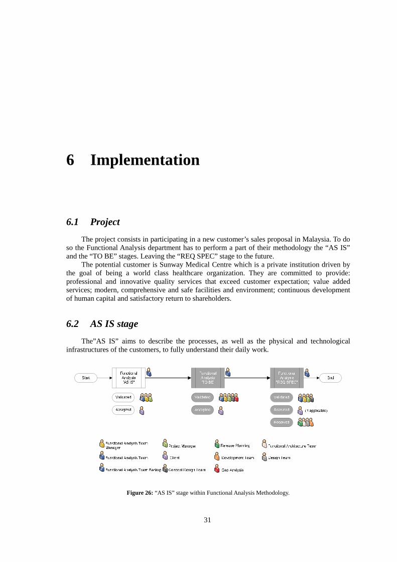
31
6 Implementation
6.1 Project
The project consists in participating in a new customer’s sales proposal in Malaysia. To do so the Functional Analysis department has to perform a part of their methodology the “AS IS” and the “TO BE” stages. Leaving the “REQ SPEC” stage to the future.
The potential customer is Sunway Medical Centre which is a private institution driven by the goal of being a world class healthcare organization. They are committed to provide: professional and innovative quality services that exceed customer expectation; value added services; modern, comprehensive and safe facilities and environment; continuous development of human capital and satisfactory return to shareholders.
6.2 AS IS stage
The”AS IS” aims to describe the processes, as well as the physical and technological infrastructures of the customers, to fully understand their daily work.
Figure 26: “AS IS” stage within Functional Analysis Methodology.
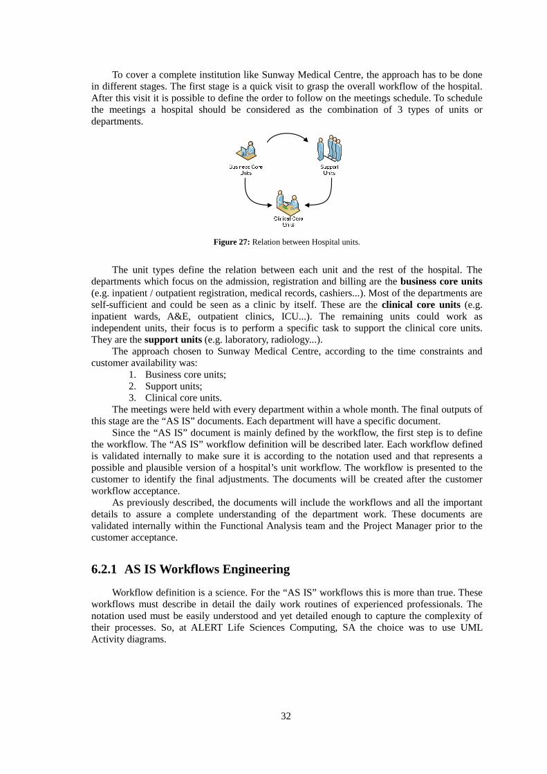
32
To cover a complete institution like Sunway Medical Centre, the approach has to be done in different stages. The first stage is a quick visit to grasp the overall workflow of the hospital. After this visit it is possible to define the order to follow on the meetings schedule. To schedule the meetings a hospital should be considered as the combination of 3 types of units or departments.
Figure 27: Relation between Hospital units.
The unit types define the relation between each unit and the rest of the hospital. The departments which focus on the admission, registration and billing are the business core units (e.g. inpatient / outpatient registration, medical records, cashiers...). Most of the departments are self-sufficient and could be seen as a clinic by itself. These are the clinical core units (e.g. inpatient wards, A&E, outpatient clinics, ICU...). The remaining units could work as independent units, their focus is to perform a specific task to support the clinical core units. They are the support units (e.g. laboratory, radiology...).
The approach chosen to Sunway Medical Centre, according to the time constraints and customer availability was:
1. Business core units; 2. Support units; 3. Clinical core units.
The meetings were held with every department within a whole month. The final outputs of this stage are the “AS IS” documents. Each department will have a specific document.
Since the “AS IS” document is mainly defined by the workflow, the first step is to define the workflow. The “AS IS” workflow definition will be described later. Each workflow defined is validated internally to make sure it is according to the notation used and that represents a possible and plausible version of a hospital’s unit workflow. The workflow is presented to the customer to identify the final adjustments. The documents will be created after the customer workflow acceptance.
As previously described, the documents will include the workflows and all the important details to assure a complete understanding of the department work. These documents are validated internally within the Functional Analysis team and the Project Manager prior to the customer acceptance.
6.2.1 AS IS Workflows Engineering
Workflow definition is a science. For the “AS IS” workflows this is more than true. These workflows must describe in detail the daily work routines of experienced professionals. The notation used must be easily understood and yet detailed enough to capture the complexity of their processes. So, at ALERT Life Sciences Computing, SA the choice was to use UML Activity diagrams.
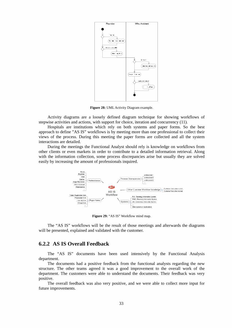
33
Figure 28: UML Activity Diagram example.
Activity diagrams are a loosely defined diagram technique for showing workflows of stepwise activities and actions, with support for choice, iteration and concurrency (11).
Hospitals are institutions which rely on both systems and paper forms. So the best approach to define ”AS IS” workflows is by meeting more than one professional to collect their views of the process. During this meeting the paper forms are collected and all the system interactions are detailed.
During the meetings the Functional Analyst should rely is knowledge on workflows from other clients or even markets in order to contribute to a detailed information retrieval. Along with the information collection, some process discrepancies arise but usually they are solved easily by increasing the amount of professionals inquired.
Figure 29: “AS IS” Workflow mind map. The “AS IS” workflows will be the result of those meetings and afterwards the diagrams
will be presented, explained and validated with the customer.
6.2.2 AS IS Overall Feedback
The “AS IS” documents have been used intensively by the Functional Analysis department.
The documents had a positive feedback from the functional analysts regarding the new structure. The other teams agreed it was a good improvement to the overall work of the department. The customers were able to understand the documents. Their feedback was very positive.
The overall feedback was also very positive, and we were able to collect more input for future improvements.
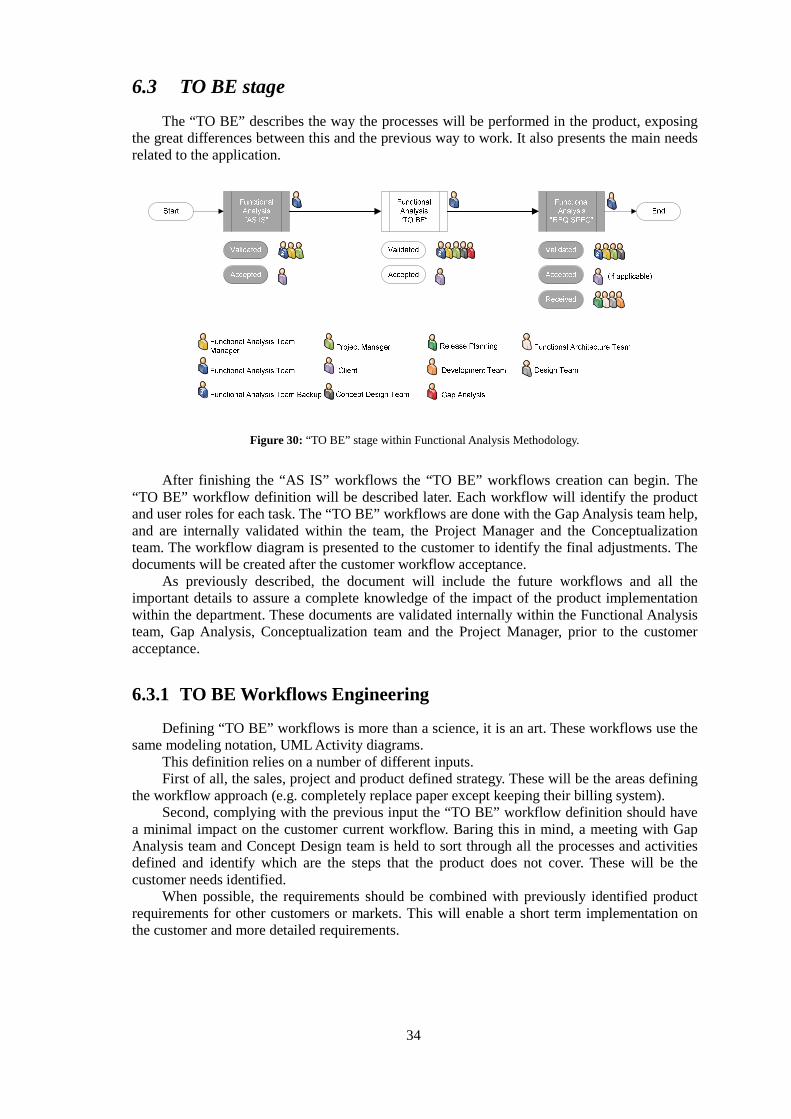
34
6.3 TO BE stage
The “TO BE” describes the way the processes will be performed in the product, exposing the great differences between this and the previous way to work. It also presents the main needs related to the application.
Figure 30: “TO BE” stage within Functional Analysis Methodology.
After finishing the “AS IS” workflows the “TO BE” workflows creation can begin. The “TO BE” workflow definition will be described later. Each workflow will identify the product and user roles for each task. The “TO BE” workflows are done with the Gap Analysis team help, and are internally validated within the team, the Project Manager and the Conceptualization team. The workflow diagram is presented to the customer to identify the final adjustments. The documents will be created after the customer workflow acceptance.
As previously described, the document will include the future workflows and all the important details to assure a complete knowledge of the impact of the product implementation within the department. These documents are validated internally within the Functional Analysis team, Gap Analysis, Conceptualization team and the Project Manager, prior to the customer acceptance.
6.3.1 TO BE Workflows Engineering
Defining “TO BE” workflows is more than a science, it is an art. These workflows use the same modeling notation, UML Activity diagrams.
This definition relies on a number of different inputs. First of all, the sales, project and product defined strategy. These will be the areas defining
the workflow approach (e.g. completely replace paper except keeping their billing system). Second, complying with the previous input the “TO BE” workflow definition should have
a minimal impact on the customer current workflow. Baring this in mind, a meeting with Gap Analysis team and Concept Design team is held to sort through all the processes and activities defined and identify which are the steps that the product does not cover. These will be the customer needs identified.
When possible, the requirements should be combined with previously identified product requirements for other customers or markets. This will enable a short term implementation on the customer and more detailed requirements.
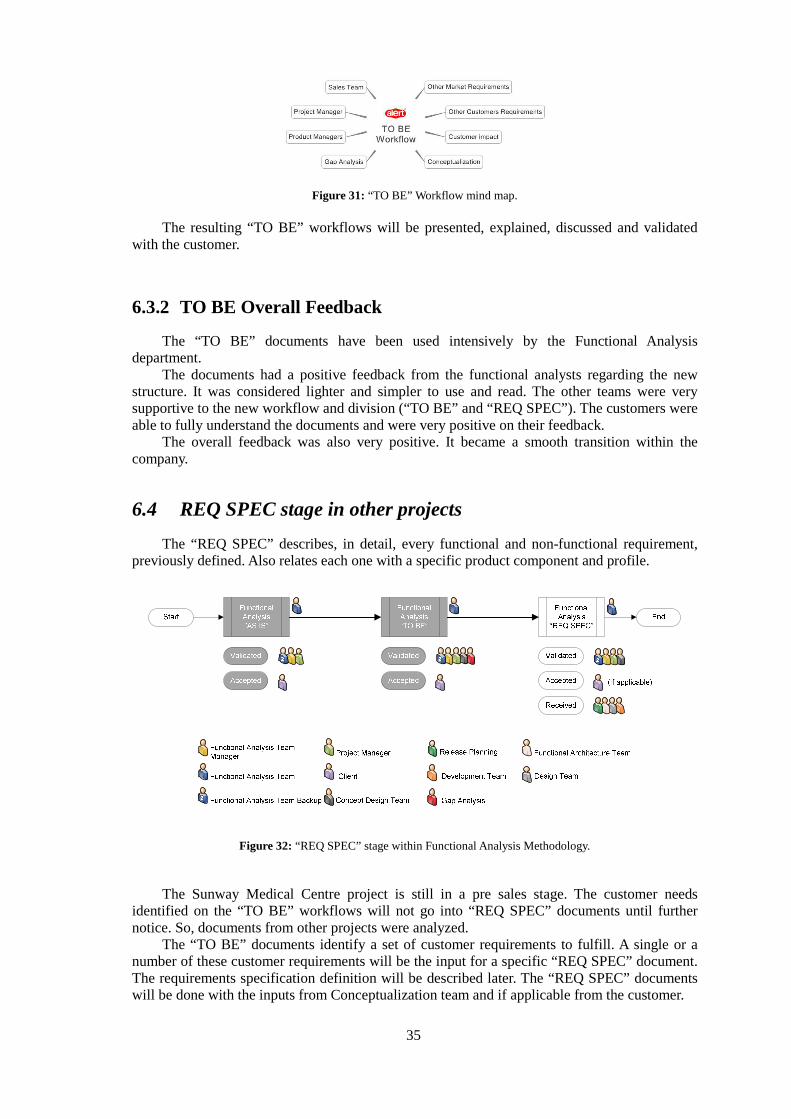
35
Figure 31: “TO BE” Workflow mind map. The resulting “TO BE” workflows will be presented, explained, discussed and validated
with the customer.
6.3.2 TO BE Overall Feedback
The “TO BE” documents have been used intensively by the Functional Analysis department.
The documents had a positive feedback from the functional analysts regarding the new structure. It was considered lighter and simpler to use and read. The other teams were very supportive to the new workflow and division (“TO BE” and “REQ SPEC”). The customers were able to fully understand the documents and were very positive on their feedback.
The overall feedback was also very positive. It became a smooth transition within the company.
6.4 REQ SPEC stage in other projects
The “REQ SPEC” describes, in detail, every functional and non-functional requirement, previously defined. Also relates each one with a specific product component and profile.
Figure 32: “REQ SPEC” stage within Functional Analysis Methodology.
The Sunway Medical Centre project is still in a pre sales stage. The customer needs identified on the “TO BE” workflows will not go into “REQ SPEC” documents until further notice. So, documents from other projects were analyzed.
The “TO BE” documents identify a set of customer requirements to fulfill. A single or a number of these customer requirements will be the input for a specific “REQ SPEC” document. The requirements specification definition will be described later. The “REQ SPEC” documents will be done with the inputs from Conceptualization team and if applicable from the customer.
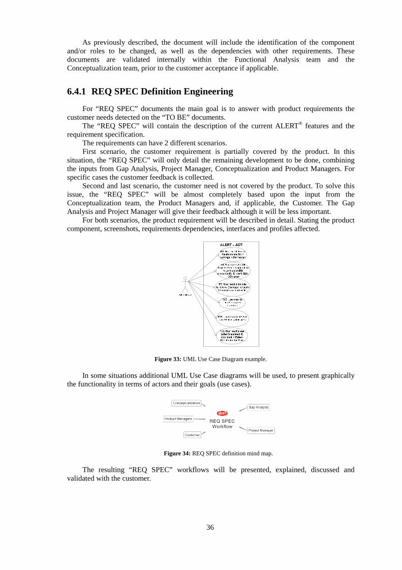
36
As previously described, the document will include the identification of the component and/or roles to be changed, as well as the dependencies with other requirements. These documents are validated internally within the Functional Analysis team and the Conceptualization team, prior to the customer acceptance if applicable.
6.4.1 REQ SPEC Definition Engineering
For “REQ SPEC” documents the main goal is to answer with product requirements the customer needs detected on the “TO BE” documents.
The “REQ SPEC” will contain the description of the current ALERT® features and the requirement specification.
The requirements can have 2 different scenarios. First scenario, the customer requirement is partially covered by the product. In this
situation, the “REQ SPEC” will only detail the remaining development to be done, combining the inputs from Gap Analysis, Project Manager, Conceptualization and Product Managers. For specific cases the customer feedback is collected.
Second and last scenario, the customer need is not covered by the product. To solve this issue, the “REQ SPEC” will be almost completely based upon the input from the Conceptualization team, the Product Managers and, if applicable, the Customer. The Gap Analysis and Project Manager will give their feedback although it will be less important.
For both scenarios, the product requirement will be described in detail. Stating the product component, screenshots, requirements dependencies, interfaces and profiles affected.
Figure 33: UML Use Case Diagram example. In some situations additional UML Use Case diagrams will be used, to present graphically
the functionality in terms of actors and their goals (use cases).
Figure 34: REQ SPEC definition mind map. The resulting “REQ SPEC” workflows will be presented, explained, discussed and
validated with the customer.
37
6.4.2 REQ SPEC Overall Feedback
The “REQ SPEC” documents have been used intensively by the Functional Analysis department.
The documents had a positive feedback from the functional analysts regarding the structure flexibility. Although it is a document with very different kinds of recipients, the other teams were very supportive to the new outline and continue to give their input for improvement. The customers understand the purpose of the document but still consider it too technical.
The overall feedback was very positive, but many improvements will still be implemented in a short term.
6.5 Conclusions
In a company like ALERT Life Sciences Computing S.A. a small change in a process has a quick and huge impact. The changes described were implemented on a number of projects around the globe:
- 88 AS IS documents done, for 19 different customers covering 5 markets - 101 TO BE documents done, for 29 different customers covering 7 markets - 93 REQ SPEC documents done, for many different customers covering 7 markets
The “acid test” resulted in a very positive overall feedback from: - functional analysts, - customers, - other teams.
38
7 Conclusions and Future Work
7.1 Goal Achievement
This dissertation is a part of an organizational effort to facilitate the implementation of CMMI (Capability Mature Model® Integration) within the software development process.
The requirements development methodology was meant to be analyzed, and more specifically the role of the Functional Analysis department.
The current workflows and templates used on the Functional Analysis department were
identified and detailed. There are 2 stages: Functional Analysis and Functional Specifications. Both result on documents describing the initial workflows and the future workflows of the customers along with the requirements definition. The customer has access to these documents, taking an active part on the definition of the requirements.
One of the main challenges was the definition of CMMI based evaluation. Given the
available resources, the 22 process areas were analyzed, and only the Requirements Development was applicable for the scope of the department focused. Using the specific goals, practices, typical work products and subpractices an evaluation matrix was defined. The ratings were based on formal SCAMPI (Standard CMMI Appraisal Method for Process Improvement) implementations. A matrix was defined to measure in quantitative and qualitative terms the current workflow and templates. It brought up a set of non-compliances and out of the scope issues.
The proposed workflow was separated in 3 stages: “AS IS”, “TO BE” and “REQ SPEC”.
The ”AS IS” stage aims to describe the processes as well as the physical and technological infrastructures of the customers, to fully understand their daily work. The “TO BE” stage describes the way the processes will be performed in the product, exposing the great differences between this and the previous way to work and presenting the main needs related to the application. The “REQ SPEC” describes in detail every functional and non-functional requirement, previously identified, and relates each one with a specific product component and profile.
The new Functional Analysis workflow and templates were proposed to minimize the non-
compliances, and implement some general documentation best practices. The result was
39
evaluated using the same criteria: specific goals, practices, typical work products and subpractices of the Requirements Development process area. The same matrix was used, the previous and new results were compared. The CMMI compliance level was clearly raised.
Along with the rest of the team, the new workflow and templates were thoroughly used by
13 professionals generating 282 documents (88 “AS IS”, 101 “TO BE” and 93 “REQ SPEC”) for 48 customers, distributed by more than 7 countries throughout 3 different continents.
The work had a positive impact in the Functional Analysis department and in the quality of
their work. The other teams awareness was raised. The customer needs are being met without jeopardizing previously defined products strategy. The product requirements are informally combined to cover more customers and markets.
The goal was achieved: the Requirements Development methodology used is now closer to
the CMMI best practices than before. The implementation of the CMMI standard at ALERT Life Sciences Computing, SA will be easier, especially at the Functional Analysis department.
7.2 Future Work
The Functional Analysis department should continue to perform these and other evaluations to their workflow and templates to keep improving their processes. During those evaluations other modeling notations (e.g. BPMN) and tools (e.g. Enterprise Architect) should be thoroughly analyzed and implemented.
To minimize the distance to the CMMI standard implementation, a project team could be
created and trained. With the needed sponsors, company alignment and resources every department could be analyzed and evaluated to identify the improvements needed.
The Capability Mature Model® Integration points the way; we just have to follow it.
40
Bibliography
1. International Institute of Business Analysis. Guide to the Business Analysis Body of Knowledge, version 1.6. s.l. : International Institute of Business Analysis, 2006. 2. Team, CMMI Product. CMMI® for Development,Version 1.2. s.l. : Carnegie Mellon University, 2006. 3. Software Engineering Institute, Carnegie Mellon. Capability Maturity Model® Integration (CMMI®) Version 1.2 Overview. s.l. : Carnegie Mellon University, 2007. 4. Team, SCAMPI Upgrade. Appraisal Requirements for CMMI®, Version 1.2 (ARC, V1.2). s.l. : Carnegie Mellon University, 2006. 5. Software Engineering Institute, Carnegie Mellon. Process Maturity Profile CMMI® For Development SCAMPISM Class A Appraisal Results 2008 End-Year Update. s.l. : Carnegie Mellon University, 2009. 6. —. Published CMMI® Appraisal Results. [Online] http://sas.sei.cmu.edu/pars/. 7. —. CMMI SCAMPI Distilled Using Appraisals for Process Improvement. s.l. : Carnegie Mellon University, 2004. 8. Team, SCAMPI Upgrade. Standard CMMI® Appraisal Method for Process Improvement (SCAMPISM ) A, Version 1.2: Method Definition Document. s.l. : Carnegie Mellon University, 2006. 9. Diane L. Gibson, Dennis R. Goldenson and Keith Kost. Performance Results of CMMI®-Based Process Improvement. s.l. : Carnegie Mellon University, 2006. 10. HCi Consulting PTy Limited. HCi Style Guide for Technical Documentation, version 3.2. s.l. : HCi Consulting PTy Limited, 2001. 11. Glossary of Key Terms. McGraw Hill. [Online] McGraw Hill. http://highered.mcgraw-hill.com/sites/0077110005/student_view0/glossary.html.