Embed Size (px)
Citation preview
INVENTORY CONTROL MANAGEMENT SYSTEM FOR
WHOLESALE BUSINESS
By
Ng Hock Li
A REPORT
SUBMITTED TO
Universiti Tunku Abdul Rahman
in partial fulfillment of the requirements
for the degree of
BACHELOR OF INFORMATION SYSTEMS (HONS)
INFORMATION SYSTEMS ENGINEERING
Faculty of Information and Communication Technology
(Perak Campus)
JANUARY 2015
BIS (Hons) Information Systems Engineering
Faculty of Information and Communication Technology (Perak Campus), UTAR ii
UNIVERSITI TUNKU ABDUL RAHMAN
REPORT STATUS DECLARATION FORM
Title: Inventory Control Management System For Wholesale Business
Academic Session: January 2015
I ______________NG HOCK LI___________________________
(CAPITAL LETTER)
declare that I allow this Final Year Project Report to be kept in
Universiti Tunku Abdul Rahman Library subject to the regulations as follows:
1. The dissertation is a property of the Library.
2. The Library is allowed to make copies of this dissertation for academic purposes.
Verified by,
_________________________ _________________________
(Author’s signature) (Supervisor’s signature)
Address:
__________________________
__________________________ _________________________
__________________________ Supervisor’s name
Date: _____________________ Date: ____________________
BIS (Hons) Information Systems Engineering
Faculty of Information and Communication Technology (Perak Campus), UTAR iii
DECLARATION OF ORIGINALITY
I declare that this report entitled “ Inventory Control Management System For Wholesale
Business ” is my own work except as cited in the references. The report has not been accepted for
any degree and is not being submitted concurrently in candidature for any degree or other award.
Signature : _________________________
Name : _________________________
Date : _________________________

BIS (Hons) Information Systems Engineering
Faculty of Information and Communication Technology (Perak Campus), UTAR iv
ACKNOWLEDGEMENT
First of all, I wish to deeply thank to my supervisor, Mr. Chee Chin Hoong for his
demonstration of guidance, providing useful advice, conceptualize the project which enabled
me to more understand the requirement of the final year project, and supervise me in
completing the final year project.
In addition, I would like to thank to Mr Su Lee Seng for his useful suggestion which enable
me to more understand about the business process of a real world company which is useful in
completing the final year project.
Other than that, I also wish to express my thanks to employee and employer of Kar Ho
company who willing to spend their time with me for providing the useful information about
the flow line of operation of Kar Ho company carry on, which enabled me to more
understand about the operation of the company that useful to completing this final year
project.
Besides that, I would like to thanks to my family members and my friends for who are giving
caring, supporting, and useful advice to me that inspired me a lot to coming out new ideas
that useful to complete the final year project.
Lastly, thanks again to all who are helped me a lot in completing this final year project.
BIS (Hons) Information Systems Engineering
Faculty of Information and Communication Technology (Perak Campus), UTAR v
ABSTRACT
The purpose of this project is going to develop a computerized inventory control
management system for Kar Ho Sdn Bhd Company. The current system that using by the Kar
Ho Company is the traditional file based system which means all transaction records, and
documentation is recorded through human manual work and it is consists of a large amount
of paper work that is not efficiency. Hence, the computerized inventory control management
system is needed for the company. The computerized inventory control management system
is designed to help the company have better data management as well as easier and a lower
cost solution on data storing.
The target user of this system is limited to the employees who are working in Kar Ho
Sdn Bhd. The chosen methodology for this system is incremental prototyping methodology.
This is because the target user of this system is the people that never use the computerized
inventory control management system before. They are new to computerized system which
means they are required through a learning phase after only able know how to manipulate the
system. With this methodology, the target user able to review, evaluate, and learn how to
operate the system before the actual implementation of the final system. Furthermore, the
design of the system would be as simple as possible which allow the target user learn and
familiar it in short period of time.
The special feature of this proposal system is the system able support in mobile
platform, there is no more limited to desktop based. With this feature, the target user is able
to access to their database at anywhere else inside company. This because of target user’s
client mostly is stay at low internet connection area which is area without 3G or higher speed.
Hence, the database is stored at the local server side. However, on mobile platform, it only
can support to view stock detail.
Other than that, this system also able to use the smartphone device acts as the barcode
scanner to scan the barcode of the product. Thus, the company able to save cost since there is
no need to purchase the barcode scanner which is costly. Since the system is able to allow
multiple users at the same time, the database is stored at the server side so that able to allow
the user access from different platform at the same time.
BIS (Hons) Information Systems Engineering
Faculty of Information and Communication Technology (Perak Campus), UTAR vi
TABLE OF CONTENTS
TITLE i
REPORT STATUS DECLARATION FORM ii
DECLARATION OF ORIGINALITY iii
ACKNOWLEDGEMENT iv
ABSTRACT v
TABLE OF CONTENTS vi - xi
LIST OF FIGURES xii - xiii
LIST OF TABLES xiv
CHAPTER 1 INTRODUCTION 1
1.1 Kar Ho Sdn Bhd Background 1
1.2 Project Background 1
1.3 Problem Statement 2 - 3
1.4 Objectives 3 - 4
1.5 Project Scope 4 - 6
1.6 Innovation and Contribution of the Project 6
CHAPTER 2 LITERATURE REVIEW 7
2.1 Study & Review on Existing Inventory System 7
2.1.1 Inventory Management System 7 - 8
2.1.2 The Use of RFID and Web 2.0 Technologies 9
2.1.3 Wal-Mart Inventory System 10
2.1.4 Automated Fingerprint Identification System 10 - 11
BIS (Hons) Information Systems Engineering
Faculty of Information and Communication Technology (Perak Campus), UTAR vii
2.1.5 Inventory Management System 11
2.1.6 Oracle Retail Store Inventory Management 12
2.2 Study on Fact Finding Methods 13
2.2.1 Interview 13
2.2.1.1 Guidelines to Perform Interview 13 - 14
2.2.1.2 Advantages & Disadvantages of Interview 15
2.2.2 Questionnaires and Surveys 15
2.2.2.1 Advantages & Disadvantages of Surveys 15
2.2.3 Observation 16
2.2.3.1 Advantages & Disadvantages of Observation 16
2.3 Comparison between Fact-Finding Methods 16 - 17
2.4 Data Collection 17 - 19
CHAPTER 3 PROPOSED METHOD/APPROACH 20
3.1 Methodology Involved (Incremental Prototype) 20 - 22
3.2 Technologies Involved 22 - 24
3.3 System Requirement 24
3.3.1 Hardware Requirement 24
3.3.2 Mobile Requirement 24
3.3.3 Software Requirement 25
3.4 System Performance Definition 25
3.5 Implementation Issues and Challenges 26
BIS (Hons) Information Systems Engineering
Faculty of Information and Communication Technology (Perak Campus), UTAR viii
3.6 Timeline 27
3.6.1 Gantt Chart 27 – 30
CHAPTER 4 SYSTEM DESIGN AND ANALYSIS 31
4.1 System Design/Overview 31
4.2 Graphic User Interface Design 32
4.2.1 Login Screen for Manager and Normal Staff 32
4.2.2 Dashboard for Manager 32
4.2.3 Dashboard for Normal Staff 33
4.2.4 Dashboard for Mobile Platform 33
4.3 Entity Relationship Diagram (ERD) 34
4.4 Business Rules 35
4.5 Data Dictionary 36
4.5.1 Customer Entity 36
4.5.2 Sales Order Entity 37
4.5.3 Sales Order Detail Entity 37 – 38
4.5.4 Payment Entity 38
4.5.5 Cheque Entity 38 - 39
4.5.6 Ship Order 39
4.5.7 Shipment Outward Entity 39 – 40
4.5.8 Product Entity 40
4.5.9 Employee Entity 40 - 41
4.5.10 Purchase Order Entity 41 – 42
BIS (Hons) Information Systems Engineering
Faculty of Information and Communication Technology (Perak Campus), UTAR ix
4.5.11 Purchase Order Detail Entity 42
4.5.12 Supplier Entity 42 – 43
4.5.13 Shipment Inward Entity 43
4.5.14 Vehicle Entity 44
4.6 Data Flow Diagram 45
4.6.1 Context Diagram 45
4.6.2 DFD Level 0 46
4.6.3 DFD 1.0 Process Order 47
4.6.4 DFD 2.0 Ship Order 47
4.6.5 DFD 3.0 Payment 48
4.6.6 DFD 4.0 Handling Inventory 48
4.6.7 DFD 5.0 Process Inward Delivery 49
4.6.8 DFD 6.0 Maintenance 49
4.6.9 DFD 8.0 Generate Report 50
4.6.10 DFD 9.0 Login 50
DFD Level 2 51
4.6.11 DFD 6.1.0 Manage Employee 51
4.6.12 DFD 6.2.0 Manage Product 51
4.6.13 DFD 6.3.0 Manage Customer 52
4.6.14 DFD 6.4.0 Manage Supplier 52
4.7 Flow Chart Diagram 53
4.7.1 Flowchart Diagram of Login Module 53
4.7.2 Flowchart Diagram of Sales Order Module 54
BIS (Hons) Information Systems Engineering
Faculty of Information and Communication Technology (Perak Campus), UTAR x
4.7.3 Flowchart Diagram of Customer Module 55
4.7.4 Flowchart Diagram of Shipment Outward 55
4.7.5 Flowchart Diagram of Payment Module 56
4.7.6 Flowchart Diagram of Product Management 57
4.7.7 Flowchart Diagram of Generate Reorder List 58
4.7.8 Flowchart Diagram of Shipment Inward 58
4.7.9 Flowchart Diagram of Management Module 59
4.7.10 Flowchart Diagram of Employee Module 60
4.7.11 Flowchart Diagram of Supplier Module 61
4.7.12 Flowchart Diagram of Report Module 62
CHAPTER 5 SYSTEM IMPLEMENTATION AND INSTALLATION 63
5.1 System Implementation 63
5.2 System Installation 64
5.2.1 Netbeans IDE Requirements 64 - 65
5.2.2 iReport Requirements 65
5.2.3 MySQL Requirements 66
CHAPTER 6 SYSTEM TESTING 67
6.1 Unit Testing 67 - 72
6.2 Functional Testing 73 - 76
6.3 Integration Testing 77
6.4 System Testing 77
BIS (Hons) Information Systems Engineering
Faculty of Information and Communication Technology (Perak Campus), UTAR xi
CHAPTER 7 CONCLUSION 78
REFERENCES 79 - 80
APPENDIX A: THE SAMPLING OF SURVEY A - 1
BIS (Hons) Information Systems Engineering
Faculty of Information and Communication Technology (Perak Campus), UTAR xii
LIST OF FIGURES
Figure Number
Title Page
Figure 2.4.1 Result of interview 19
Figure 3.1.1 Incremental Method 20
Figure 3.2.1 Netbeans IDE Logo 22
Figure 3.2.2 Eclipse ADT Logo 23
Figure 3.2.3 MySQL Logo 23
Figure 3.6.1.1 Gantt Chart Table (Activity 1 - 50) 27 – 29
Figure 3.6.1.2 Gantt Chart Diagram (Activity 1 - 30) 29
Figure 3.6.1.3 Gantt Chart Diagram (Activity 30 – 50) 30
Figure 4.2.1 Login GUI 32
Figure 4.2.2 Dashboard design for manager 32
Figure4.2.3 Dashboard design for normal staff 33
Figure 4.2.4 Dashboard design for mobile platform 33
Figure 4.3 ERD Diagram 34
Figure 4.6.1 Context Diagram 45
Figure 4.6.2 DFD Level 0 46
Figure 4.6.3 DFD 1.0 Process Order 47
Figure 4.6.4 DFD 2.0 Ship Order 47
Figure 4.6.5 DFD 3.0 Payment 48
Figure 4.6.6 DFD 4.0 Handling Inventory 48
Figure 4.6.7 DFD 5.0 Process Inward Delivery 49
Figure 4.6.8 DFD 6.0 Maintenance 49
Figure 4.6.9 DFD 8.0 Generate Report 50
Figure 4.6.10 DFD 9.0 Login 50
Figure 4.6.11 DFD 6.1.0 Manage Employee 51
Figure 4.6.12 DFD 6.2.0 Manage Product 51
BIS (Hons) Information Systems Engineering
Faculty of Information and Communication Technology (Perak Campus), UTAR xiii
Figure 4.6.13 DFD 6.3.0 Manage Customer 52
Figure 4.6.14 DFD 6.4.0 Manage Supplier 52
Figure 4.7.1 Flow Chart Diagram of Login Module 53
Figure 4.7.2 Flow Chart Diagram of Sales Order Module 54
Figure 4.7.3 Flow Chart Diagram of Customer Module 55
Figure 4.7.4 Flow Chart Diagram of Shipment Outward 55
Figure 4.7.5 Flow Chart Diagram for Payment Module 56
Figure 4.7.6 Flow Chart for Product Management 57
Figure 4.7.7 Flow Chart for Generate Reorder List 58
Figure 4.7.8 Flow Chart for Shipment Inward 58
Figure 4.7.9 Flow Chart for Management Module 59
Figure 4.7.10 Flow Chart for Employee Module 60
Figure 4.7.11 Flow Chart for Supplier Module 61
Figure 4.7.12 Flow Chart for Report Generation Module 62
BIS (Hons) Information Systems Engineering
Faculty of Information and Communication Technology (Perak Campus), UTAR xiv
LIST OF TABLES
Table Number Title
Page
Table 3.3.1 Hardware requirement for system end-user 24
Table 3.3.2 Mobile requirement for system end-user 24
Table 3.3.3 Software requirement for system end-user 25
Table 5.2.1.1 Hardware Requirements for Netbeans IDE 64
Table 5.2.1.2 Software Requirements for Netbeans IDE 65
Table 5.2.2.1 Hardware Requirements for iReport 65
Table 5.2.2.2 Software Requirements for iReport 65
Table 5.2.3.1 Hardware Requirements for MySQL 66
Table 5.2.3.2 Software Requirements for MySQL 66
Table 6.1.1 Unit Testing 1 – Login as system user 67 - 68
Table 6.1.2 Unit Testing 2 – Register new customer information into system 68
Table 6.1.3 Unit Testing 3 – Register new supplier information into
system
69
Table 6.1.4 Unit Testing 4 – Creating new sales order 69 - 70
Table 6.1.5 Unit Testing 5 – Creating new purchase order 70
Table 6.1.6 Unit Testing 6 – Creating new product information 70 - 71
Table 6.1.7 Unit Testing 7 – Payment for each sales order 71
Table 6.1.8 Unit Testing 8 – Creating new product information 72
Table 6.2.1 Functional Testing 1 – Login using different roles 73
Table 6.2.2 Functional Testing 2 – Customer sales order debt 73 - 74
Table 6.2.3 Functional Testing 3 – Company purchase order debt 74
Table 6.2.4 Functional Testing 4 – Vehicle delivery order 75
Table 6.2.5 Functional Testing 5 – Print report 75
Table 6.2.6 Functional Testing 6 – Make payment 76
Table 6.2.7 Functional Testing 7 – Product quantity checking 76
CHAPTER 1 INTRODUCTION
BIS (Hons) Information Systems Engineering
Faculty of Information and Communication Technology (Perak Campus), UTAR 1
CHAPTER 1 INTRODUCTION
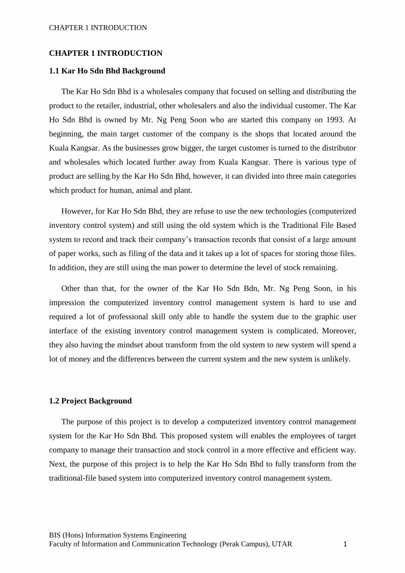
1.1 Kar Ho Sdn Bhd Background
The Kar Ho Sdn Bhd is a wholesales company that focused on selling and distributing the
product to the retailer, industrial, other wholesalers and also the individual customer. The Kar
Ho Sdn Bhd is owned by Mr. Ng Peng Soon who are started this company on 1993. At
beginning, the main target customer of the company is the shops that located around the
Kuala Kangsar. As the businesses grow bigger, the target customer is turned to the distributor
and wholesales which located further away from Kuala Kangsar. There is various type of
product are selling by the Kar Ho Sdn Bhd, however, it can divided into three main categories
which product for human, animal and plant.
However, for Kar Ho Sdn Bhd, they are refuse to use the new technologies (computerized
inventory control system) and still using the old system which is the Traditional File Based
system to record and track their company’s transaction records that consist of a large amount
of paper works, such as filing of the data and it takes up a lot of spaces for storing those files.
In addition, they are still using the man power to determine the level of stock remaining.
Other than that, for the owner of the Kar Ho Sdn Bdn, Mr. Ng Peng Soon, in his
impression the computerized inventory control management system is hard to use and
required a lot of professional skill only able to handle the system due to the graphic user
interface of the existing inventory control management system is complicated. Moreover,
they also having the mindset about transform from the old system to new system will spend a
lot of money and the differences between the current system and the new system is unlikely.
1.2 Project Background
The purpose of this project is to develop a computerized inventory control management
system for the Kar Ho Sdn Bhd. This proposed system will enables the employees of target
company to manage their transaction and stock control in a more effective and efficient way.
Next, the purpose of this project is to help the Kar Ho Sdn Bhd to fully transform from the
traditional-file based system into computerized inventory control management system.
CHAPTER 1 INTRODUCTION
BIS (Hons) Information Systems Engineering
Faculty of Information and Communication Technology (Perak Campus), UTAR 2
1.3 Problem Statement
The Kar Ho Company is a wholesale company that still using the Traditional File Based
system to record and track their company’s transaction records. There are some problems
domains and drawbacks facing by the Kar Ho Company which are:
a) Space Consuming & Difficulty in Finding Specify Files
As the company getting grows, the documentation (customers’ records, suppliers’
records, transaction records and etc.) increase at the same time. Hence, there is more
file cabinets is required by the company in order to keep those document files,
meanwhile more space needed for place the file cabinets which may led to increase
cost on expand the office. In addition, since those files were located separately in
different file cabinets, as result it will increase the difficulty in finding the specify file
when needed.
b) Poor Security & Short Durability of Data
For the Traditional File Based system, all documentations are kept in hardcopy; it is
easily lost or gets stolen by other. Furthermore, once the files been stolen, there is no
backup to restore the missing files which may cause loss of profit earned (e.g. missing
of the record of customer’s unpaid bill). Besides that, since the record is recorded on
paper, which unable to hold the data for more than 20 years, as the papers are
biodegradable, or being destroyed by pests. The paper also easily damaged by the
disasters (e.g. fire disaster, flood and etc.)
c) Poor Management of Inventory
Since the current system using by the company is the Traditional File Based System,
which mean the quantity of the stock left is counted by man power. Hence, it may
miscalculate on the remaining stock or oversight the stock that already is out of stock.
Therefore, it can cause the current customer move to another company which is able
to supply the products their requested.
d) Data Inconsistency
The new stored data maybe will same as previously entered data by the owner or
other workers. This is because the Traditional File Based System does not allow the
user to check for the availability of the data before entering the duplicated data and
CHAPTER 1 INTRODUCTION
BIS (Hons) Information Systems Engineering
Faculty of Information and Communication Technology (Perak Campus), UTAR 3
the data inserted are not bind together; as all data are consist of one single file folder
and without any connection. Thus, there may have a lot of duplicated data exist in the
records that can lead the manager to make wrong decision.
e) Inefficiency on Report Generation
Since all record is stored in hardcopy, it is rely to human power to generate report
which is required a lot of time to process and produce. Moreover, there also easily
generate wrong detail report since all document are put separately that may cause
missed of certain important information.
1.4 Objectives
The main objective of this proposed system is to deliver a comprehensive, all-rounded
system and more user friendly graphic user interface for the target user, which enable the
target user have a better data management as well as easier and a lower cost solution on data
storing.
a) Reduce the searching time
The proposed system enabled the user to store the data into system with a better
management of the data and details of the inventory. With using the new system that
is computerized, all the documentation is transform into softcopy and stored inside
computer. With this, it enable the user more easily search the specify information
through entering the specify detail (e.g. name, date and etc.).
b) Protect the important information
Since the proposed system is computerized system, it enabled the user (manager) to
set the restriction for their employees about that which part of the information the
employees have the right to access through. With this, the employees only can view
the specify data that they should be see. Furthermore, since all documentation is
stored in softcopy, it can easily make backup for the information as prevent any
important information lost due to the incident happened. The company also not need
to worry about the expiry of the data, as the data will not destroyed by nature disaster
or pest, unless the data has been removed or deleted.
CHAPTER 1 INTRODUCTION
BIS (Hons) Information Systems Engineering
Faculty of Information and Communication Technology (Perak Campus), UTAR 4
c) Avoid stock-outs
Through using the inventory control management system, the user can easily keep
track the level of the stock left, and manage to make order on the product without
excess or only out of stock only make order. Furthermore, when the product is
reached the reorder level, the system will alert the specify role of user for notice them
that the specific product is reached the reorder level.
d) Keep track on sales record
The proposed system enabled the user the keep track customers’ transaction record.
When a customer that is still owing the company money for few month and he/she is
coming to purchase, the system will track out the record of the customer by entering
their name or the IC. Moreover, it also able to determine which product is the best sell
product that can bring profit to the company.
1.5 Project Scope
This proposed system is restricted only to the employees of Kar Ho Company and it is
includes several important modules that each of it is functioning with unique functions. There
modules are listed as below:
a) Report Module
This module is to generate the desired report for the user, for instance the sales report,
staff report, customer report, monthly report and end of report. User is able to choose
which kind of report to be generated. For example, through generate the weekly report
can expose the high demand for one specific product that is not being stored in the
quantities required. However, this module only allows the user that position is
manager to use. The user login with the normal staff position is unable to perform this
feature.
b) Inventory Management Module
This module is to handle the product availability in the warehouse. The feature of this
module is to keep track on the inventory levels for all products that available in the
warehouse. Once the product is reached the reorder point, the system will prompt out
CHAPTER 1 INTRODUCTION
BIS (Hons) Information Systems Engineering
Faculty of Information and Communication Technology (Perak Campus), UTAR 5
the message to show that which product is reached the reorder point and the details of
the suppliers that is selling this product.
c) Delivery Module
This module is used to handle the order of the customer to deliver the product to them.
With this module, the user able to use the system to keep tracks the delivery status of
the customer order. It also will record down which employees is in charge for this
delivery. This can prevent the error happen that deliver the ordered product to
customer that has been delivered before.
d) Payment Module
This module is to handle the payment made by customer for instance the amount and
mode of the payment. The system is able to list out the payment that done by the
customer and the customer still owe how much. Other than that, the user is able to
search the customer through their name or IC to determine that the customer still
owing to company or not.
e) Sales Order Module
This module is to handle the order made by the customer. The system will record the
order made by customer, and its details e.g. shipping address, the ordered product and
etc. With this, the company won’t miss up any customer.
f) Purchase Order Module
This module is to handle the order that to make to supplier. With this feature, the user
able to keep track the order made to supplier and the product is supplied by which
supplier. Other than that, once there are two suppliers is providing same product, the
system will list detail out like the day required from being order until the product
arrived and the cost of product and etc.
g) Login Module
This module is to handle user who can access to the system. The staff with different
position will have different accessibility. For example, if the user is login as the
manager, the system is allows the user to update the price of product, generate the
CHAPTER 1 INTRODUCTION
BIS (Hons) Information Systems Engineering
Faculty of Information and Communication Technology (Perak Campus), UTAR 6
report and etc. Besides that, if user is login as normal staff, the system will not allow
the user to alter the price of product.
1.6 Innovation and Contribution of The Project
Compare to other existing inventory system, there is some innovations can be included in
this project. First of all, the system able to access through mobile platform, as it is not
platform depending, the user can access to the data in database by using the terminal or the
mobile devices such as the Android smartphone or the Android powered tablet. This is
because nowadays smartphone device is become a common object in life and it always close
at hand. With this features, the user is able to check the stock quantity and make order to the
suppliers without going back to the office to open the terminal for checking purpose.
Besides that, the system also able to use the Android device acts as the barcode scanner to
scan the barcode of the product. This able to let the company to save cost from being
purchase the expensive barcode scanner. The Android OS will be the first considering
platform because it is an open source which will not cause any use of money. Other than that,
there is a lot of solution in the Internet about the Android platform in which the developer
will easily search for solution. In additions, Android platform is now a most widely used
mobile platform in which the user can easily get the Android device and start to use it with
the Android platform.
Lastly, the system is allows the staff to search the product through the Android device.
The user enter the name of product and the information about the product will immediately
be sent over a digital network to the company’s inventory database and the result will sent
back to the Android device. Everything can be done portable as long as the user smartphone
is in a connection enable mode. The system will be develop in the most cheapest way as
almost everything that use in developing this software is open source which cause the
developer invest in zero.
CHAPTER 2 LITERATURE REVIEW
BIS (Hons) Information Systems Engineering
Faculty of Information and Communication Technology (Perak Campus), UTAR 7
CHAPTER 2 LITERATURE REVIEW
Before start to develop the proposed system, study and review on previous existing
inventory control management system is important which enabled the developer to develop a
more useful and efficient inventory control management system. Besides that, the proper
development tools are also one of the important factors that will affect the quality of system.
Other than that, another factor is the users’ requirements gathering techniques which enable
the developer more understand and know about the system’s features required from aspect of
user. Therefore, there are some studies and researches have been done and shown at below:
2.1 Study & Review on Existing Inventory Control Management System
Through the journal and article that had studied, there are several existing system has
been chosen to compare for getting a better understanding about the inventory control
management system. There are some problems or features that can be improve and some of
the features were considering as perfect for current global technology.
2.1.1 Inventory Management System
Firstly, the first benchmarked system that has been chosen is the “Inventory Management
System” (Arina et al., 2006). The main purpose of this system is to create a system that is
able to connect to a multiple stores and warehouses by using server and client. Based on the
system that they created, one of the strengths of this system is the cash register interface will
be work with the barcode inputs. Besides that, the connection between the client and server is
provided with this system that enables the client to make an order through the inventory
system. Other than that, to prevent the data from getting hack, the Secure Socket Layer (SSL)
is used to secure their internet connection. This system can be used by multiple stores or
warehouses since they can connect to each other. However, the weaknesses of this system are
the theft may break the synchronization between the inventory and database. The level of the
security to secure the data was depending on the accuracy of restocking procedure. It enable
the theft may take a chance in restocking procedure to steal the data.
CHAPTER 2 LITERATURE REVIEW
BIS (Hons) Information Systems Engineering
Faculty of Information and Communication Technology (Perak Campus), UTAR 8
Since this existing system is more focused on the security between server and client, there
are some solutions or recommendation to improve its features. In the cash registers interface,
there is some extra features can added on it. Some of the barcode is hard to scan by the
barcode hardware and it may cause frustration to the customer who waiting for long times.
However, the user still can manually enter the barcode to get the correct description and price
of the product but it may take longer times if every barcode is facing same problems. The
solution suggested for this problem is voice input. The voice input can be disabled and only
enable when the users need it. Microphone is needed for this feature. The user can speak out
the barcode through microphone into the system and the system will record the number that
user speaks out to get the related items from the database. For an example, the user are trying
to speak 12345’ then the system interface will prompt out the number for users to confirm
whether the barcode is correct and belong to that product. With this feature, it is able to save
time when the barcode hardware is having problem and unavailable to scan the barcode and
can avoid the user from manually typing. However, there are some weaknesses for this
feature which is the surrounding situation can’t be too noisy as it will influence on the voice
input. By the way, it should not be a big problem if the surrounding situation is silent or not
so noisy. To overcome this problem, headphone will be a good choice since it able to reduce
the noise of the situation. Next, according to the article that had been reviewed, they have
provided a connection between server and client, and a link between multiple stores or
warehouses. Based on their features, there is some enhancement can makes on their features.
First, improve the system to able to connect every branch. By doing so, every branch can to
connect with each other’s. Sometimes one of the branches might be out of stock and they can
use the system to contact with other branch in order to borrow stock. They send the
information through the features provided by the system. The receiver will get an alert once
the received the request. Other than that, the transmitted data is encrypted when being
transmitting and the data will decrypted by the system once is reached to other branch.
However, the weakness for this system which is the data transfer may become slow due to the
huge process. This problem can be overcome by using faster internet connection.
CHAPTER 2 LITERATURE REVIEW
BIS (Hons) Information Systems Engineering
Faculty of Information and Communication Technology (Perak Campus), UTAR 9
2.1.2 The Use of RFID and Web 2.0 Technologies to Improve Inventory Management
According to another article that had been reviewed and related to the inventory
management system which entitled “The Use of RFID and Web 2.0 Technologies to Improve
Inventory Management” (Sizakele et al., 2011), they have conducted the investigation on the
inventory management system for the purpose of understanding the current technology. Due
to their research that had been done on inventory management system, they have listed out
the most problem faced by current inventory system which is inventory running using paper-
based systems, excel files, and traditional enterprise software that make the whole operation
become costly and inefficiency.
By the way, in order to improve the inventory system, Radio Frequency Identification
(RFID) have been introduced and has bring out the result that shown to be the top available
technology in order to improve the inventory management for most enterprise nowadays.
RFID technology enables real-time reading of products, eliminating of counterfeiting,
product misplacement, reduce the theft cases, replenishment of stock on shelves, and etc.
However, they have found out some weaknesses of RFID which is that if the inventory
products have accidentally misplaced on other shelves or the quantity on hand of the products
is low, inventory worker may identified it late or found out after they have make a check
through the stand-alone database or server in an organization which will lead to time
consuming and delay of work. Besides that, RFID technology does not provide features that
give notification and update to the inventory manager on what is happening on their
inventories through their cell phones. So, they have proposed a solution regarding to the
problem they have found out during their research which is integrated the use of Web2.0 Tool
such as Twitter with RFID technology to make sure that the inventory managers will be
informed and get updated at anytime and anywhere on the Internet using cell phones.
Through this solution, the inventory manager able to make immediate decision without
having physical involvement of the problem happens to their inventory. With this feature
provided, it will help to improve the process and management of the inventories anywhere
anytime as well as the analysis on the top sales products and low sales products.
However, there is drawback of the solution provided by them which is the cost of the
development of the combination technology of RFID and Web 2.0 Tool. The budget to
develop such system is big and once the system had done, they might hard to earn back the
profit since the budget may over the profit.
CHAPTER 2 LITERATURE REVIEW
BIS (Hons) Information Systems Engineering
Faculty of Information and Communication Technology (Perak Campus), UTAR 10
2.1.3 Wal-Mart Inventory System
According to another article that had reviewed, it has talked about the computer system
that used by the “Wal-Mart Inventory System” (Nara Mondigo, 2008). They have mentioned
that current system that used by them will auto alert when the product balance drops to the
recorder point. This feature seems like attractive and it still can be improved. The system can
be improved by using auto order. For an example, once the product balance drops to the
recorder point, the system will alert the user and prompt out the message to request the user
to make a restock from supplier. The user is allow to change the setting to the auto order
which mean that the order request will automatic send to the supplier when the product
balance drops to the recorder point.
However, there is a limitation for this features which is the system will need to read the
information in the database and if the system failure occur, the alert will not be prompt out.
For the solution to overcome this problems, user is highly recommend to checks their stock
from time to time. Other than that, the system also won’t able to select different supplier that
providing same good with different price. To solve this problem, the system can set to will
compare which cost will be lower and only that will send the order request to supplier.
2.1.4 Automated Fingerprint Identification System (AFIS)
Next, according to the research that had been done by the Kenneth R. Moses about the
“Automated Fingerprint Identification System (AFIS)” article, AFIS nowadays are widely
used in the global. It is a biometric system which the main purpose is developed to control the
crime rates, criminal, and so on. Due to the era technologies that is changing from time to
time nowadays, the biometric has widely used and some of the company has already applied
this method into their system. Mostly such biometric system is used to control the attendance
or limit the access of the staff for some purpose. Because of this, the staff nowadays will use
their fingerprint to check in to their workplace for record down the attendance. This system
had also integrated into the inventory control system. The staff will have to use their
fingerprint to access to the system and make some operation. By doing so, it is very secure
and the company system will not easily hack by outsider. Since everything is secure by the
AFIS, it makes everything easily to be control.
CHAPTER 2 LITERATURE REVIEW
BIS (Hons) Information Systems Engineering
Faculty of Information and Communication Technology (Perak Campus), UTAR 11
However, not many of the system will preferred this features since it need the additional
hardware and installation. Staff has to use their staff card to check in first and after the staff
card had been identified, fingerprint is needed to match the two records. By doing so, it can
prevent from cheating. Staff has to apply for the leaves if they can’t go to work and cheated
will not work since this features is use. Next, biometric system is well-known as one of the
most expensive type system in which not every company can afford it. Although the security
is very strong, but since the crime rates is increase nowadays, people might scare that their
part of body will be very dangerous as people will do anything to achieve what they want.
2.1.5 Inventory Management System
According to the article that had been view and make investigation which entitled
“Inventory Management System” (Thomas Bronack, 2012), he has make an investigation
about the inventory management system. The inventory system that had been reviewed by
him is all about the Centralized Inventory Repository. It has stated that the inventory control
system is very important for the company. It is because the inventory control system will help
in ensuring the efficiency and effectiveness in managing the inventory. It has the strength in
controlling the data since it is integrate with the database which makes everything in well
controlled. Next, the systems will automatic help in filter the different roles of user in which
they will only able to use the features based on their roles. The successfully inventory control
system should have three things in which the system will be known as successful system
when this three things exists in the system. The three things that included consists of the
history details about the asset, the criticality is defined for each of the asset, and the system
has provide the financial details which is related to the company asset. Because of this, the
system proposed by him included these three things and make the developed system satisfied
by user who used the system.
However, there are several weaknesses exists in the Centralized Inventory Repository.
The inventory management is performed by too many various groups which make the
database is hard to plan. By using this method, the database must be plan nicely and time
consuming. Since everything performed through the automated system, the staff may to
depend on the system which sometimes the system down will cause everything become out of
control and the accuracy of the data cannot be guarantee.
CHAPTER 2 LITERATURE REVIEW
BIS (Hons) Information Systems Engineering
Faculty of Information and Communication Technology (Perak Campus), UTAR 12
2.1.6 Oracle Retail Store Inventory Management
Based on the article that had been review and make investigation which entitled “Oracle
Retail Store Inventory Management” by the Oracle Retail, they have makes an investigation
about the inventory management system. They realized that the problem that faced by retailer
nowadays is the out of stock problems which cause the retailer is unable to provide the items
to the buyer. Because of this, they had develop the system for the purpose of overcome this
problems. The developed system has stated to maintain the accuracy of tracking the
information of the products, purchase order, and sales order. The system used is connected to
the cloud server database which make everything is backed up to the system and more secure
compare to local database. Next, it consists of some strength in their system in their system in
which the main purpose is to prevent out of stock and overstock problems in the specific store.
It also helps in increasing the accurate of the inventory in which the stock count capability is
applied.
However, it consists of some weaknesses in their system in which the system has
limitation in performing some function. The system has no provide the stock delivery features
in which the user cannot set the schedule for the vehicle to deliver the stock in the specific
time. Most of the inventory company nowadays will need the stock delivery feature which is
currently needed by every business. Other than that, the system provided by them is not so
friendly interface since it is too many data displayed in one page. For those who not good in
using the computerized system may refuse to use it due to the complicated of the user
interface.
CHAPTER 2 LITERATURE REVIEW
BIS (Hons) Information Systems Engineering
Faculty of Information and Communication Technology (Perak Campus), UTAR 13
2.2 Study on Fact Finding Methods
Without knowing the requirements, it is difficult to build a solution (Tom Mochal, 2008).
It is means that the researcher or developer will have to know the customer requirement
before they started to develop something. According to the article entitled “10 Techniques for
Gathering Requirements” (Tom Mochal, 2008), it had mentioned that it is very important to
perform the requirement gathering in each project. There are 10 recommended steps which
includes the face-to-face interviews method, group interviews, facilitated sessions, joint
application development, questionnaires, prototyping, use cases, following people around,
proposal of the project, and brainstorming. By referring to the steps, there are quite several
steps that had been implemented in this project in order to get the complete image of the
project requirements. Hence, with using a good and proper requirements gathering method, it
is able to help in extracting the accurate needs of the users on how the software should be.
Next, the small investigation has been made to make sure that which of the methods should
be used in gather the requirements. There are a lot of existing methods to collect the users’
requirement in which the most common methods includes the interview, questionnaires,
observation, and survey. The comparison among methods has been made to choose the most
suitable methods for this project.
2.2.1 Interview
The interview is the fact-finding method that is most frequently be used to collect the
required information. It enabled the developer to communicate with the end user face-to-face
in order to collect the information which can help to figure and more comprehend about the
process workflow (O’Brien, 2003).
2.2.1.1 Guidelines to Perform Interview
There is few step is included to perform the interview which is:
Step 1: Decide who be the interviewee
This is important step to get accurate information. By selecting different interviewee, it will
help in gathering different information which is benefit to us. In order to collect the
information, the key user must be selected to interview.
CHAPTER 2 LITERATURE REVIEW
BIS (Hons) Information Systems Engineering
Faculty of Information and Communication Technology (Perak Campus), UTAR 14
Step 2: Design and create suitable questions for interview
There are several types of questions can be designed in the interview in order to get the
information. It can be divided into three category which are open-ended, closed-ended and
question with range of responses. For the open-ended question, it is the question that
encourages spontaneous and unstructured responses from the interviewees. While for the
close-ended question, is will limit the response such as the question with multiple choices and
only one of them is answer. Next, the range of response questions is the types of closed-
ended question. However, the question provided will only have limited answers that allow
respondents to choose. Normally the question will consists of a numeric scale for each
question that asked respondents to respond on it.
Step 3: Plan for interview session
The interview must be plan well once the previous step had done. The things that need to be
plan and prepare in this step will be an arrangement of schedule with the interviewee. The
interviewer will need to inform the interviewee about the planned schedule by using the
communication methods such as make a call to the interviewee, emailing, SMS, and so on.
Other than the planned schedule, the location where the interview conducted will also need to
inform to the interviewee.
Step 4: Conduct the interview
After everything had settled down, the interview will begin as planned in previous step. The
interview will need an interviewer to begin by introducing themselves before start to
questioning the interviewee. The question should be asked in the order in which the question
had prepared. The interviewer should record down every important point that given by the
interviewee so that every important points can be summarize at last.
Step 5: Document and evaluate the interview
Document the gathered information and summarize it to become useful information that the
project development needed. By doing so, the developer will know what actually the
interviewee wants and it will give the developer benefits while developing the software.
CHAPTER 2 LITERATURE REVIEW
BIS (Hons) Information Systems Engineering
Faculty of Information and Communication Technology (Perak Campus), UTAR 15
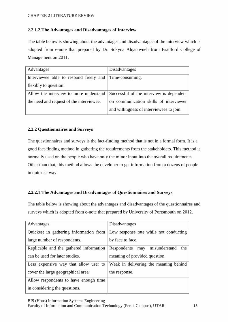
2.2.1.2 The Advantages and Disadvantages of Interview
The table below is showing about the advantages and disadvantages of the interview which is
adopted from e-note that prepared by Dr. Sokyna Alqatawneh from Bradford College of
Management on 2011.
Advantages Disadvantages
Interviewee able to respond freely and
flexibly to question.
Time-consuming.
Allow the interview to more understand
the need and request of the interviewee.
Successful of the interview is dependent
on communication skills of interviewer
and willingness of interviewees to join.
2.2.2 Questionnaires and Surveys
The questionnaires and surveys is the fact-finding method that is not in a formal form. It is a
good fact-finding method in gathering the requirements from the stakeholders. This method is
normally used on the people who have only the minor input into the overall requirements.
Other than that, this method allows the developer to get information from a dozens of people
in quickest way.
2.2.2.1 The Advantages and Disadvantages of Questionnaires and Surveys
The table below is showing about the advantages and disadvantages of the questionnaires and
surveys which is adopted from e-note that prepared by University of Portsmouth on 2012.
Advantages Disadvantages
Quickest in gathering information from
large number of respondents.
Low response rate while not conducting
by face to face.
Replicable and the gathered information
can be used for later studies.
Respondents may misunderstand the
meaning of provided question.
Less expensive way that allow user to
cover the large geographical area.
Weak in delivering the meaning behind
the response.
Allow respondents to have enough time
in considering the questions.
CHAPTER 2 LITERATURE REVIEW
BIS (Hons) Information Systems Engineering
Faculty of Information and Communication Technology (Perak Campus), UTAR 16
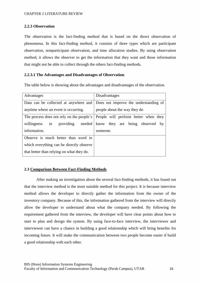
2.2.3 Observation
The observation is the fact-finding method that is based on the direct observation of
phenomena. In this fact-finding method, it consists of three types which are participant
observation, nonparticipant observation, and time allocation studies. By using observation
method, it allows the observer to get the information that they want and those information
that might not be able to collect through the others fact-finding methods.
2.2.3.1 The Advantages and Disadvantages of Observation
The table below is showing about the advantages and disadvantages of the observation.
Advantages Disadvantages
Data can be collected at anywhere and
anytime where an event is occurring.
Does not improve the understanding of
people about the way they do
The process does not rely on the people’s
willingness in providing needed
information.
People will perform better when they
know they are being observed by
someone.
Observe is much better than word in
which everything can be directly observe
that better than relying on what they do.
2.3 Comparison Between Fact-Finding Methods
After making an investigation about the several fact-finding methods, it has found out
that the interview method is the most suitable method for this project. It is because interview
method allows the developer to directly gather the information from the owner of the
inventory company. Because of this, the information gathered from the interview will directly
allow the developer to understand about what the company needed. By following the
requirement gathered from the interview, the developer will have clear points about how to
start to plan and design the system. By using face-to-face interview, the interviewer and
interviewee can have a chance in building a good relationship which will bring benefits for
incoming future. It will make the communication between two people become easier if build
a good relationship with each other.
CHAPTER 2 LITERATURE REVIEW
BIS (Hons) Information Systems Engineering
Faculty of Information and Communication Technology (Perak Campus), UTAR 17
Next, since the proposed system will use by the company itself, it is good to have an
interview with them rather than using other methods. Although questionnaire method allow
developer to get a lot of fact-finding result, but sometimes the respondents may not be able to
give personal opinion since everything is fixed at questionnaires. Because of this, interview
methods might be much better as they can have chance and freedom in giving opinions.
Besides that, the observation may also not a best solution in gathering information. It need a
lot of time in observing something. The collected result may not accurate too since everyone
will have their different ideas in which sometimes the observer might judge on something
based on their personal thinking.
As a result, the interview method will be chosen as a main method in gathering
information. It is good if the developer can directly communicate with the respondents as it
can bring a lot of benefits to each other. The system can be developed based on the
respondents answer and may reduce the misunderstood of the user requirements.
2.4 Data Collection
The data collected from the fact-finding is the interview method. The result is
collected from the interview that conducted to the Kar Ho Sdn Bhd. Since data collection is a
very important stage, the process need to be serious. It is because no matter how good the
system developed by the developer, it may still not be able to meet the user requirement since
no information that gathered from the user. Based on the answer given by the respondent, the
developer is understood what is their requirement and how to work on the system.
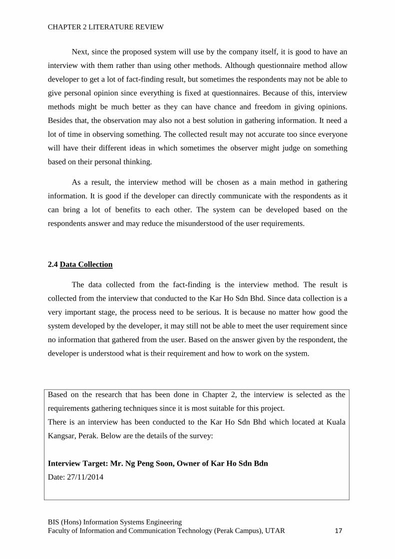
Based on the research that has been done in Chapter 2, the interview is selected as the
requirements gathering techniques since it is most suitable for this project.
There is an interview has been conducted to the Kar Ho Sdn Bhd which located at Kuala
Kangsar, Perak. Below are the details of the survey:
Interview Target: Mr. Ng Peng Soon, Owner of Kar Ho Sdn Bdn
Date: 27/11/2014
CHAPTER 2 LITERATURE REVIEW
BIS (Hons) Information Systems Engineering
Faculty of Information and Communication Technology (Perak Campus), UTAR 18
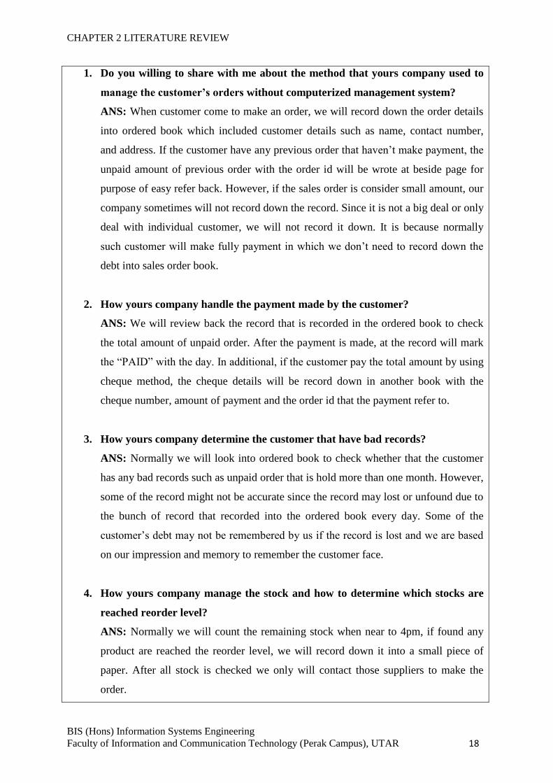
1. Do you willing to share with me about the method that yours company used to
manage the customer’s orders without computerized management system?
ANS: When customer come to make an order, we will record down the order details
into ordered book which included customer details such as name, contact number,
and address. If the customer have any previous order that haven’t make payment, the
unpaid amount of previous order with the order id will be wrote at beside page for
purpose of easy refer back. However, if the sales order is consider small amount, our
company sometimes will not record down the record. Since it is not a big deal or only
deal with individual customer, we will not record it down. It is because normally
such customer will make fully payment in which we don’t need to record down the
debt into sales order book.
2. How yours company handle the payment made by the customer?
ANS: We will review back the record that is recorded in the ordered book to check
the total amount of unpaid order. After the payment is made, at the record will mark
the “PAID” with the day. In additional, if the customer pay the total amount by using
cheque method, the cheque details will be record down in another book with the
cheque number, amount of payment and the order id that the payment refer to.
3. How yours company determine the customer that have bad records?
ANS: Normally we will look into ordered book to check whether that the customer
has any bad records such as unpaid order that is hold more than one month. However,
some of the record might not be accurate since the record may lost or unfound due to
the bunch of record that recorded into the ordered book every day. Some of the
customer’s debt may not be remembered by us if the record is lost and we are based
on our impression and memory to remember the customer face.
4. How yours company manage the stock and how to determine which stocks are
reached reorder level?
ANS: Normally we will count the remaining stock when near to 4pm, if found any
product are reached the reorder level, we will record down it into a small piece of
paper. After all stock is checked we only will contact those suppliers to make the
order.
CHAPTER 2 LITERATURE REVIEW
BIS (Hons) Information Systems Engineering
Faculty of Information and Communication Technology (Perak Campus), UTAR 19
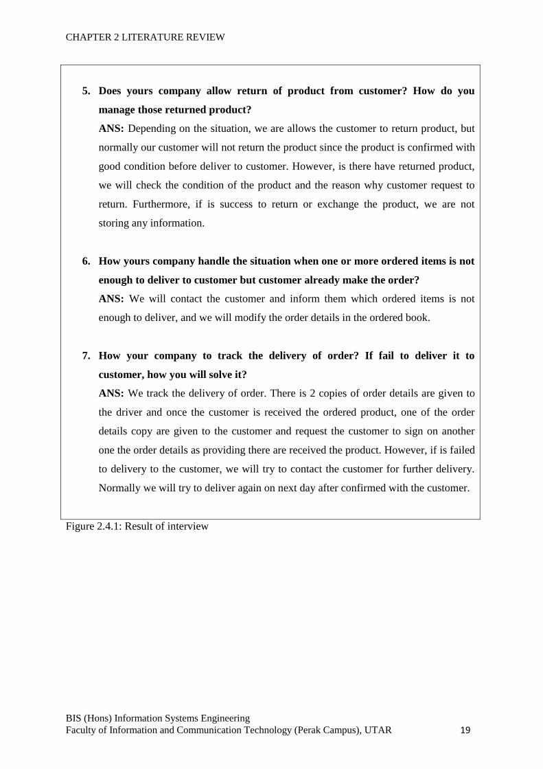
5. Does yours company allow return of product from customer? How do you
manage those returned product?
ANS: Depending on the situation, we are allows the customer to return product, but
normally our customer will not return the product since the product is confirmed with
good condition before deliver to customer. However, is there have returned product,
we will check the condition of the product and the reason why customer request to
return. Furthermore, if is success to return or exchange the product, we are not
storing any information.
6. How yours company handle the situation when one or more ordered items is not
enough to deliver to customer but customer already make the order?
ANS: We will contact the customer and inform them which ordered items is not
enough to deliver, and we will modify the order details in the ordered book.
7. How your company to track the delivery of order? If fail to deliver it to
customer, how you will solve it?
ANS: We track the delivery of order. There is 2 copies of order details are given to
the driver and once the customer is received the ordered product, one of the order
details copy are given to the customer and request the customer to sign on another
one the order details as providing there are received the product. However, if is failed
to delivery to the customer, we will try to contact the customer for further delivery.
Normally we will try to deliver again on next day after confirmed with the customer.
Figure 2.4.1: Result of interview
CHAPTER 3 PROPOSED METHOD/APPROACH
BIS (Hons) Information Systems Engineering
Faculty of Information and Communication Technology (Perak Campus), UTAR 20
CHAPTER 3 PROPOSED METHOD/APPROACH
3.1 Methodology Involved (Incremental Prototype)
The methodology chosen for the system development must be appropriate and suitable for the
system and the developer must follow the step-by-step as mention in the guideline for able to
deliver the system successfully and on time (Kim, 2011).
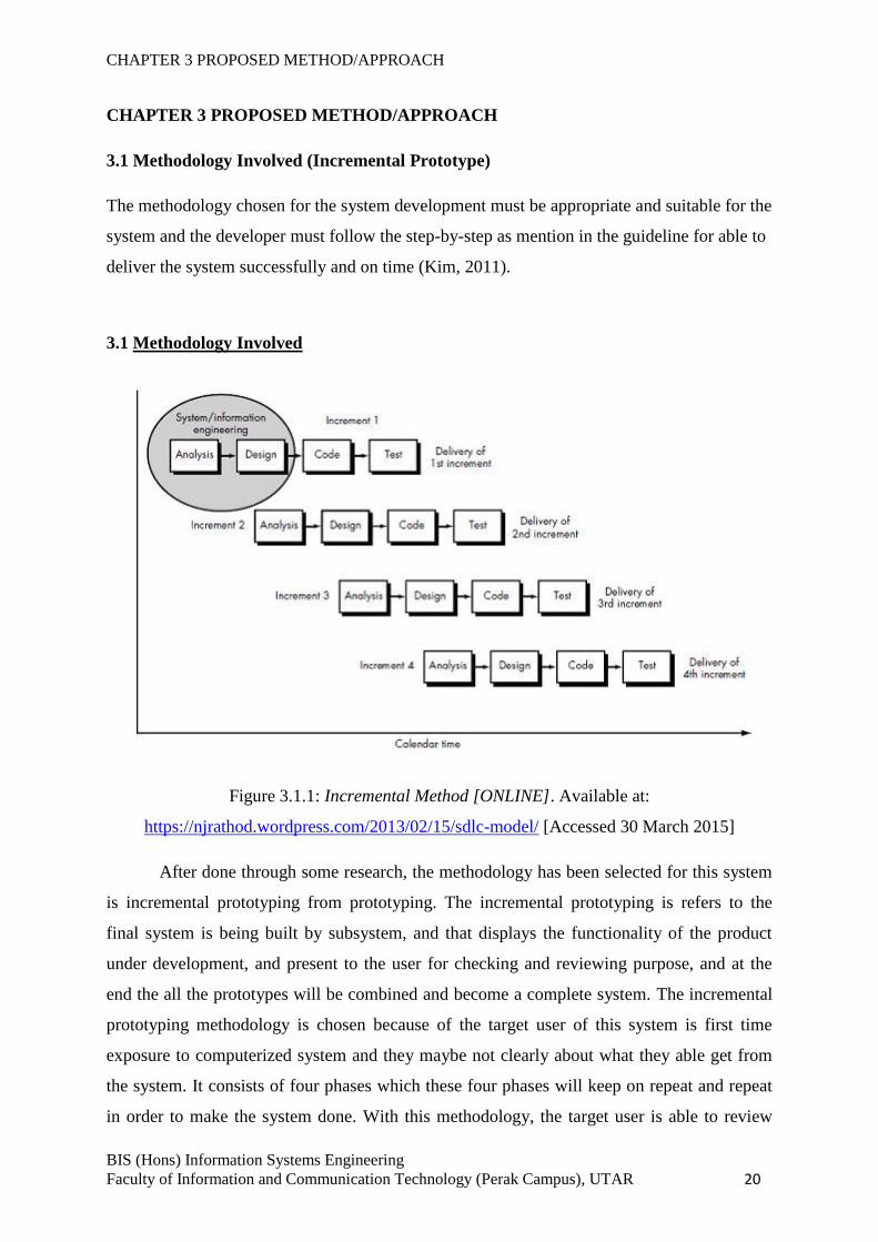
3.1 Methodology Involved
Figure 3.1.1: Incremental Method [ONLINE]. Available at:
https://njrathod.wordpress.com/2013/02/15/sdlc-model/ [Accessed 30 March 2015]
After done through some research, the methodology has been selected for this system
is incremental prototyping from prototyping. The incremental prototyping is refers to the
final system is being built by subsystem, and that displays the functionality of the product
under development, and present to the user for checking and reviewing purpose, and at the
end the all the prototypes will be combined and become a complete system. The incremental
prototyping methodology is chosen because of the target user of this system is first time
exposure to computerized system and they maybe not clearly about what they able get from
the system. It consists of four phases which these four phases will keep on repeat and repeat
in order to make the system done. With this methodology, the target user is able to review
CHAPTER 3 PROPOSED METHOD/APPROACH
BIS (Hons) Information Systems Engineering
Faculty of Information and Communication Technology (Perak Campus), UTAR 21
and evaluate the developed proposal and try it before the actual implementation of the final
system. Meanwhile, at the same time the user is able to experience the how was the system
able to support in their business and they may able to skip training courses for learning how
use the system when the final system is developed. It is also helping the developer to
understand the user requirement which are more specific and the particular requirement may
not been considered by the developer during the design of the product.
Following are the steps and approaches to design a software prototype:
a) Basic requirement identification
In this stage, few of the inventory control management software that done by other
programmer will be reviewed to get the basic understanding about the requirements of
inventory control management software, especially the user interface. The
complicated details of the internal design of the system, and the external features like
performance and security may be ignore at this stage. Other than that, the requirement
also gathered from the target user about what is the expectation of the system from
them.
b) Developing the initial prototype
In this stage, the first prototype of the system is developed and the basic requirements
of the system will be showing out. Yet, the functions of the system may not perform
exactly same to the actual software. It is used to give the visual look and feel to the
customer how the system will going be.
c) Review of the prototype
The designed prototype that has been developed is present to the customer, and other
important stakeholders. After that, the feedback from them is collected and will be
used as further improvement of the system under development stage.
d) Revise and enhance the prototype
In this stage, the reply and comments from the user will be analysed to more
understand about the user requirement and the aspect of the user toward the system.
However, there may will having some negotiations between the customer and
developer due to the required time and budget limitation and technical feasibility of
CHAPTER 3 PROPOSED METHOD/APPROACH
BIS (Hons) Information Systems Engineering
Faculty of Information and Communication Technology (Perak Campus), UTAR 22
the actual implementation. The new prototype being develops and cycle repeatedly
until fulfil the user requirement and achieve user satisfaction.
3.2 TECHNOLOGIES INVOLVED
The technology that involved in this particular system will be Java language and also
the Android language, since the system will build on NetBeans IDE platform for the terminal,
as well as the Eclipse ADT for Android tool that build the part for the mobile devices, and
Microsoft Azure.
Figure 3.2.1: Netbeans IDE Logo [ONLINE]. Available at
https://github.com/Team254/FRC-2013/wiki/Installing-Java-and-NetBeans [Accessed 30
March 2015]
Netbeans IDE
Netbeans is the IDE which means Integrated Development Environment. The program acts
like a text editor that allows the developer to edit the code, compiles, and deploys the code. It
is a software development platform that allow user to create a system using Java. It is popular
software that the Java developer always used for the development purpose. Next, it is a
freeware which the developer can use it without paying any money. It will be a main software
platform in this project for developing the Java desktop-based application. Thus, there will be
the other software platform use to support the development.
CHAPTER 3 PROPOSED METHOD/APPROACH
BIS (Hons) Information Systems Engineering
Faculty of Information and Communication Technology (Perak Campus), UTAR 23
Figure 3.2.2: Eclipse ADT Logo [ONLINE]. Available at https://eclipse.org/downloads/
[Accessed 30 March 2015]
Eclipse ADT
Eclipse is a software platform that allows Android developer to develop their own Android
apps by using it. It is a freeware which the developer can use it without paying any money. It
will be a main software platform use to develop the Android-based application. Other than
that, Eclipse itself is integrated together with Java 8 which the Java 8 will be a support for the
Eclipse.
Figure 3.2.3: Microsoft Azure Logo [ONLINE]. Available at http://www.sitepoint.com/save-
mysql-sign-petition/ [Accessed 31 March 2015]
MySQL
MySQL is a well-known relational database management system. Since it is an open source
and friendly user, majority of the developer will choose to use MySQL in developing their
system. Official websites is provided for everyone to go to download the MySQL installer.
MySQL can support or integrate with other development software in a perfect way. Other
than that, MySQL so far can support different platform in which will helps in easier the work
for developer.
CHAPTER 3 PROPOSED METHOD/APPROACH
BIS (Hons) Information Systems Engineering
Faculty of Information and Communication Technology (Perak Campus), UTAR 24
Software and Hardware Requirements for Development Platform
The software and hardware that required for develop this system are as follow:
Platform: NetBeans IDE 8.0 version, Eclipse and Eclipse ADT for Android.
Language: Java, Android languages.
Hardware: Laptop / Desktop that has minimum 1GB memory, 256GB disk space,
mobile devices such as smart phone or tablets that powered by Android platform.
Database: MySQL
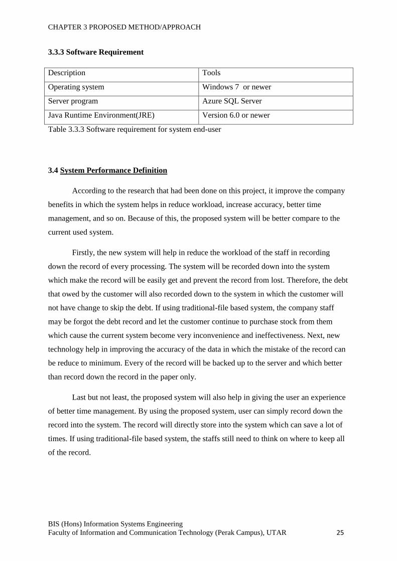
3.3 SYSTEM REQUIREMENT
3.3.1 Hardware Requirement
Description Minimum Requirements
Processor I3 processor with 2.0GHz or higher
Memory 1GB RAM or higher
Storage Minimum 1GB of available storage space
Video Card DirectX 9 or higher
Resolution 1024 x 768 or higher
Table 3.3.1 Hardware requirement for system end-user
3.3.2 Mobile Requirement
Description Minimum Requirements
Operating system Android platform with 2.3.6 or newer
Processor Dual-core processor or higher
Memory 512MB or higher
Storage Minimum 20MB available storage space
Camera 5Megapixel or higher
Table 3.3.2 Mobile requirement for system end-user
CHAPTER 3 PROPOSED METHOD/APPROACH
BIS (Hons) Information Systems Engineering
Faculty of Information and Communication Technology (Perak Campus), UTAR 25
3.3.3 Software Requirement
Description Tools
Operating system Windows 7 or newer
Server program Azure SQL Server
Java Runtime Environment(JRE) Version 6.0 or newer
Table 3.3.3 Software requirement for system end-user
3.4 System Performance Definition
According to the research that had been done on this project, it improve the company
benefits in which the system helps in reduce workload, increase accuracy, better time
management, and so on. Because of this, the proposed system will be better compare to the
current used system.
Firstly, the new system will help in reduce the workload of the staff in recording
down the record of every processing. The system will be recorded down into the system
which make the record will be easily get and prevent the record from lost. Therefore, the debt
that owed by the customer will also recorded down to the system in which the customer will
not have change to skip the debt. If using traditional-file based system, the company staff
may be forgot the debt record and let the customer continue to purchase stock from them
which cause the current system become very inconvenience and ineffectiveness. Next, new
technology help in improving the accuracy of the data in which the mistake of the record can
be reduce to minimum. Every of the record will be backed up to the server and which better
than record down the record in the paper only.
Last but not least, the proposed system will also help in giving the user an experience
of better time management. By using the proposed system, user can simply record down the
record into the system. The record will directly store into the system which can save a lot of
times. If using traditional-file based system, the staffs still need to think on where to keep all
of the record.
CHAPTER 3 PROPOSED METHOD/APPROACH
BIS (Hons) Information Systems Engineering
Faculty of Information and Communication Technology (Perak Campus), UTAR 26
3.5 Implementation Issues and Challenges
Based on the research and investigation, each of the projects that existed will have its
own challenges and issues. Most of the developer will face an issues and challenges when
every time the project reaches at the implementation stage.
There are some problems and challenges facing during implementation of this system.
First of all, the concurrency problem that may occur during the process of updating the record.
Since the proposed system is able to support in different platform which is running in
computer (desktop and laptop) and the mobile device that running Android operating system,
there have the chance that the multiple user will update the same row of record at the same
time. With this problem, the record maybe will become inconsistent and deliver wrong
information to the end-user. After searching the solution from online, the solution that
suitable to solve this problem is matching the data before update it. Once the data is retrieved
from the database, the one copy of original data will stored at buffer storage, and when the
user is clicked the update button, the query will match the stored original data with the
original data inside database, the update action only will perform after the stored original data
is matched with the data in database.
Apart from this, another challenge that facing is developing the mobile apps. This is
because the Android code is still new for the developer and never tried it before. By solving
this problem, the developer can learn the Android code through online since nowadays the
Android code is famous and can easily found on websites. However, the developer will need
to consume some time in order to fully understand how the Android code is work.
Moreover, there is a challenge for the synchronization between the databases. Once
the system is lost the connection to the server database, the system will store the record on
local and once is reconnected to the server; the record will be synchronized between the local
databases with the server databases.
CHAPTER 3 PROPOSED METHOD/APPROACH
BIS (Hons) Information Systems Engineering
Faculty of Information and Communication Technology (Perak Campus), UTAR 27
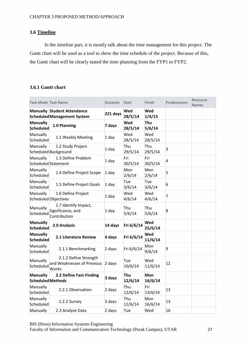
3.6 Timeline
In the timeline part, it is mostly talk about the time management for this project. The
Gantt chart will be used as a tool to show the time schedule of the project. Because of this,
the Gantt chart will be clearly stated the time planning from the FYP1 to FYP2.
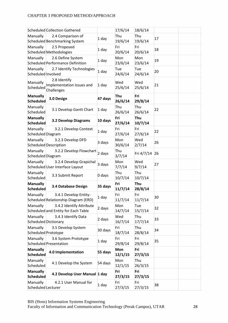
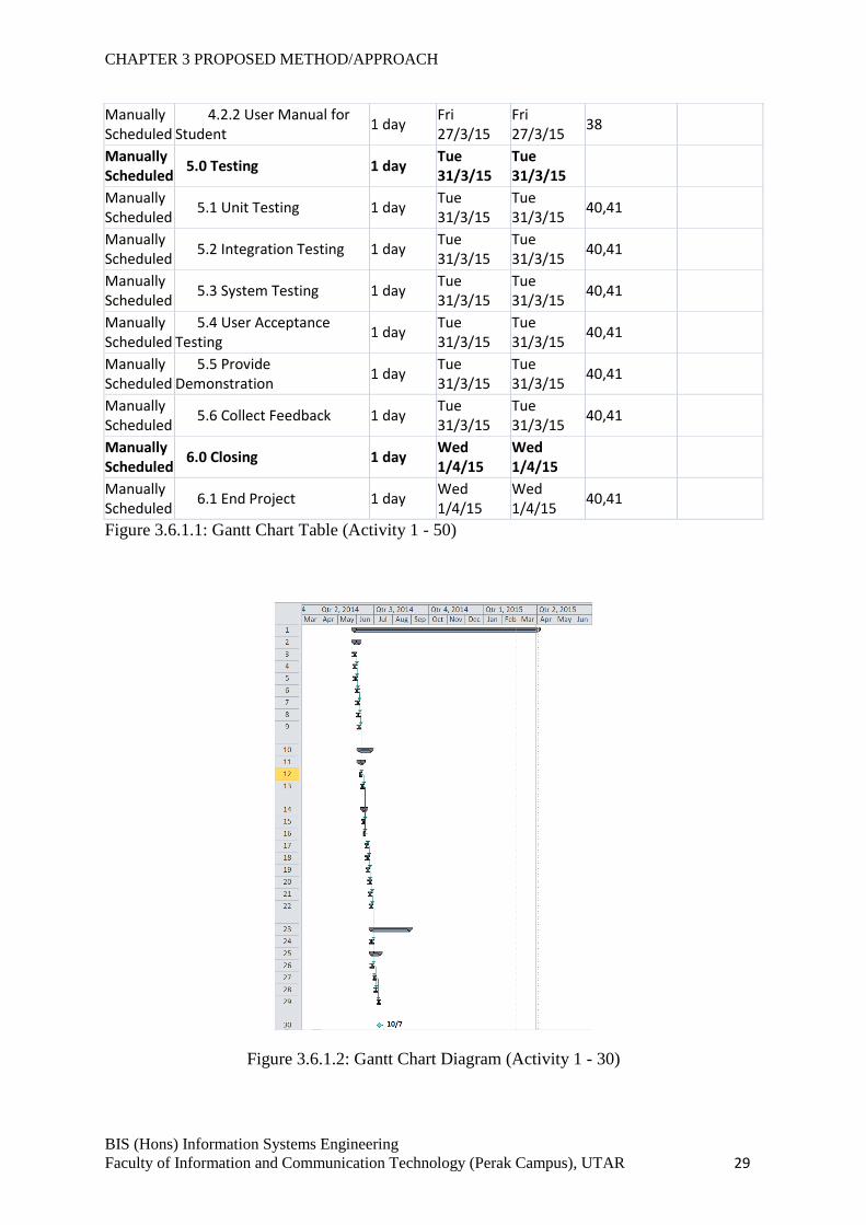
3.6.1 Gantt chart
Task Mode Task Name Duration Start Finish Predecessors Resource Names
Manually Scheduled
Student Attendance Management System
221 days Wed 28/5/14
Wed 1/4/15
Manually Scheduled
1.0 Planning 7 days Wed 28/5/14
Thu 5/6/14
Manually Scheduled
1.1 Weekly Meeting 1 day Wed 28/5/14
Wed 28/5/14
Manually Scheduled
1.2 Study Project Background
1 day Thu 29/5/14
Thu 29/5/14
3
Manually Scheduled
1.3 Define Problem Statement
1 day Fri 30/5/14
Fri 30/5/14
4
Manually Scheduled
1.4 Define Project Scope 1 day Mon 2/6/14
Mon 2/6/14
5
Manually Scheduled
1.5 Define Project Goals 1 day Tue 3/6/14
Tue 3/6/14
6
Manually Scheduled
1.6 Define Project Objectives
1 day Wed 4/6/14
Wed 4/6/14
7
Manually Scheduled
1.7 Identify Impact, Significance, and Contribution
1 day Thu 5/6/14
Thu 5/6/14
8
Manually Scheduled
2.0 Analysis 14 days Fri 6/6/14 Wed 25/6/14
Manually Scheduled
2.1 Literature Review 4 days Fri 6/6/14 Wed 11/6/14
Manually Scheduled
2.1.1 Benchmarking 2 days Fri 6/6/14 Mon 9/6/14
9
Manually Scheduled
2.1.2 Define Strength and Weaknesses of Previous Works
2 days Tue 10/6/14
Wed 11/6/14
12
Manually Scheduled
2.2 Define Fact-Finding Methods
3 days Thu 12/6/14
Mon 16/6/14
Manually Scheduled
2.2.1 Observation 2 days Thu 12/6/14
Fri 13/6/14
13
Manually Scheduled
2.2.2 Survey 3 days Thu 12/6/14
Mon 16/6/14
13
Manually 2.3 Analyze Data 2 days Tue Wed 16
CHAPTER 3 PROPOSED METHOD/APPROACH
BIS (Hons) Information Systems Engineering
Faculty of Information and Communication Technology (Perak Campus), UTAR 28
Scheduled Collection Gathered 17/6/14 18/6/14
Manually Scheduled
2.4 Comparison of Benchmarking System
1 day Thu 19/6/14
Thu 19/6/14
17
Manually Scheduled
2.5 Proposed Methodologies
1 day Fri 20/6/14
Fri 20/6/14
18
Manually Scheduled
2.6 Define System Performance Definition
1 day Mon 23/6/14
Mon 23/6/14
19
Manually Scheduled
2.7 Identify Technologies Involved
1 day Tue 24/6/14
Tue 24/6/14
20
Manually Scheduled
2.8 Identify Implementation Issues and Challenges
1 day Wed 25/6/14
Wed 25/6/14
21
Manually Scheduled
3.0 Design 47 days Thu 26/6/14
Fri 29/8/14
Manually Scheduled
3.1 Develop Gantt Chart 1 day Thu 26/6/14
Thu 26/6/14
22
Manually Scheduled
3.2 Develop Diagrams 10 days Fri 27/6/14
Thu 10/7/14
Manually Scheduled
3.2.1 Develop Context Diagram
1 day Fri 27/6/14
Fri 27/6/14
22
Manually Scheduled
3.2.3 Develop DFD Description
3 days Mon 30/6/14
Wed 2/7/14
26
Manually Scheduled
3.2.2 Develop Flowchart Diagram
2 days Thu 3/7/14
Fri 4/7/14 26
Manually Scheduled
3.2.4 Develop Grapichal User Interface Layout
3 days Mon 7/7/14
Wed 9/7/14
27
Manually Scheduled
3.3 Submit Report 0 days Thu 10/7/14
Thu 10/7/14
Manually Scheduled
3.4 Database Design 35 days Fri 11/7/14
Thu 28/8/14
Manually Scheduled
3.4.1 Develop Entity-Relationship Diagram (ERD)
1 day Fri 11/7/14
Fri 11/7/14
30
Manually Scheduled
3.4.2 Identify Attribute and Entity for Each Table
2 days Mon 14/7/14
Tue 15/7/14
32
Manually Scheduled
3.4.3 Identify Data Dictionary
2 days Wed 16/7/14
Thu 17/7/14
33
Manually Scheduled
3.5 Develop System Prototype
30 days Fri 18/7/14
Thu 28/8/14
34
Manually Scheduled
3.6 System Prototype Presentation
1 day Fri 29/8/14
Fri 29/8/14
35
Manually Scheduled
4.0 Implementation 55 days Mon 12/1/15
Fri 27/3/15
Manually Scheduled
4.1 Develop the System 54 days Mon 12/1/15
Thu 26/3/15
Manually Scheduled
4.2 Develop User Manual 1 day Fri 27/3/15
Fri 27/3/15
Manually Scheduled
4.2.1 User Manual for Lecturer
1 day Fri 27/3/15
Fri 27/3/15
38
CHAPTER 3 PROPOSED METHOD/APPROACH
BIS (Hons) Information Systems Engineering
Faculty of Information and Communication Technology (Perak Campus), UTAR 29
Manually Scheduled
4.2.2 User Manual for Student
1 day Fri 27/3/15
Fri 27/3/15
38
Manually Scheduled
5.0 Testing 1 day Tue 31/3/15
Tue 31/3/15
Manually Scheduled
5.1 Unit Testing 1 day Tue 31/3/15
Tue 31/3/15
40,41
Manually Scheduled
5.2 Integration Testing 1 day Tue 31/3/15
Tue 31/3/15
40,41
Manually Scheduled
5.3 System Testing 1 day Tue 31/3/15
Tue 31/3/15
40,41
Manually Scheduled
5.4 User Acceptance Testing
1 day Tue 31/3/15
Tue 31/3/15
40,41
Manually Scheduled
5.5 Provide Demonstration
1 day Tue 31/3/15
Tue 31/3/15
40,41
Manually Scheduled
5.6 Collect Feedback 1 day Tue 31/3/15
Tue 31/3/15
40,41
Manually Scheduled
6.0 Closing 1 day Wed 1/4/15
Wed 1/4/15
Manually Scheduled
6.1 End Project 1 day Wed 1/4/15
Wed 1/4/15
40,41
Figure 3.6.1.1: Gantt Chart Table (Activity 1 - 50)
Figure 3.6.1.2: Gantt Chart Diagram (Activity 1 - 30)
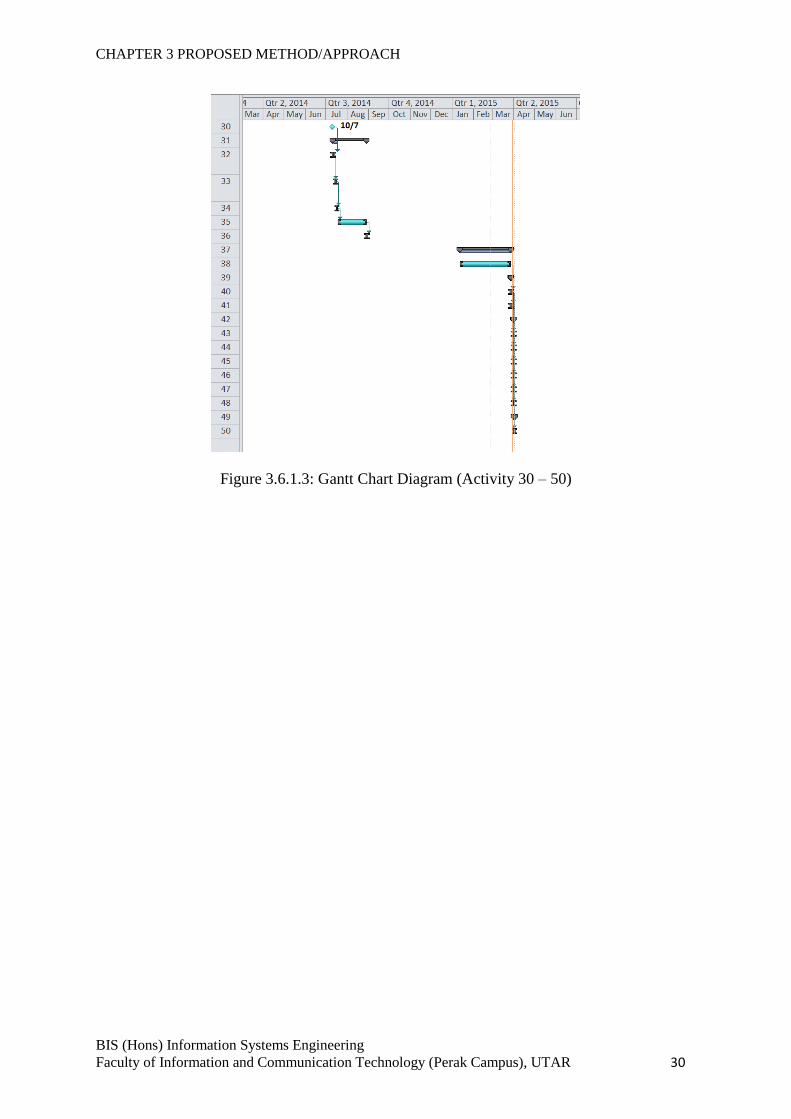
CHAPTER 3 PROPOSED METHOD/APPROACH
BIS (Hons) Information Systems Engineering
Faculty of Information and Communication Technology (Perak Campus), UTAR 30
Figure 3.6.1.3: Gantt Chart Diagram (Activity 30 – 50)
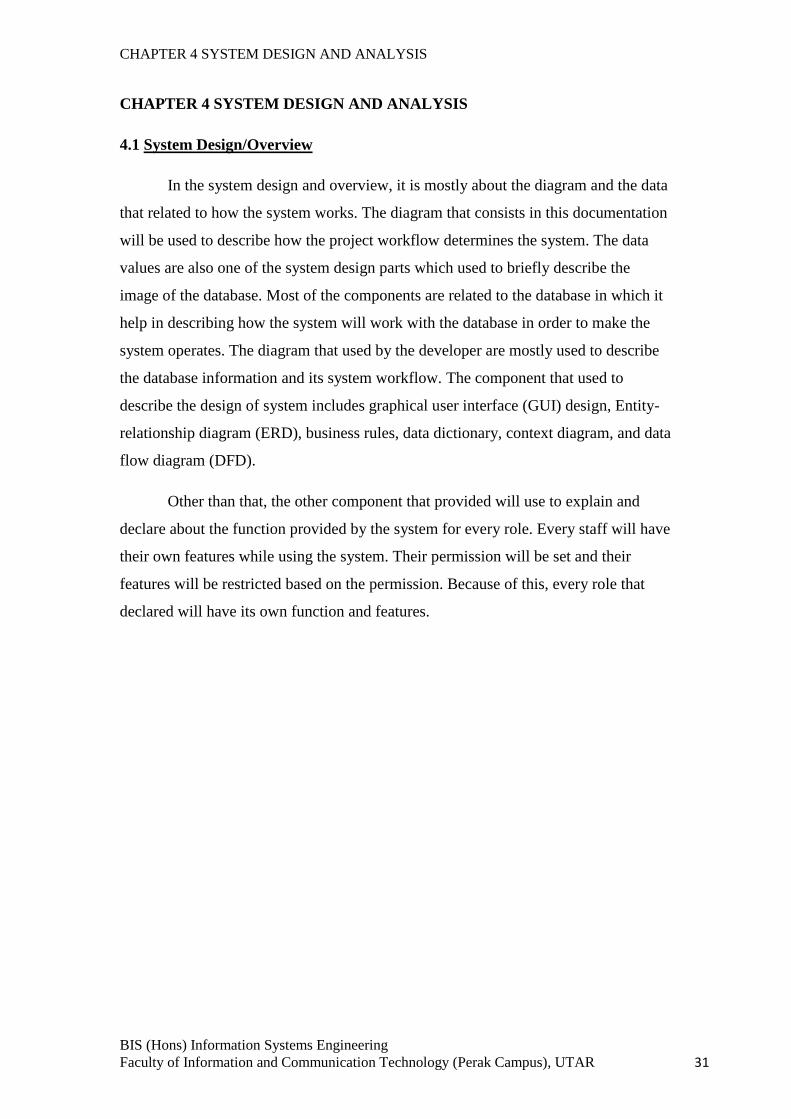
CHAPTER 4 SYSTEM DESIGN AND ANALYSIS
BIS (Hons) Information Systems Engineering
Faculty of Information and Communication Technology (Perak Campus), UTAR 31
CHAPTER 4 SYSTEM DESIGN AND ANALYSIS
4.1 System Design/Overview
In the system design and overview, it is mostly about the diagram and the data
that related to how the system works. The diagram that consists in this documentation
will be used to describe how the project workflow determines the system. The data
values are also one of the system design parts which used to briefly describe the
image of the database. Most of the components are related to the database in which it
help in describing how the system will work with the database in order to make the
system operates. The diagram that used by the developer are mostly used to describe
the database information and its system workflow. The component that used to
describe the design of system includes graphical user interface (GUI) design, Entity-
relationship diagram (ERD), business rules, data dictionary, context diagram, and data
flow diagram (DFD).
Other than that, the other component that provided will use to explain and
declare about the function provided by the system for every role. Every staff will have
their own features while using the system. Their permission will be set and their
features will be restricted based on the permission. Because of this, every role that
declared will have its own function and features.
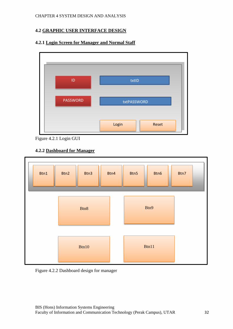
CHAPTER 4 SYSTEM DESIGN AND ANALYSIS
BIS (Hons) Information Systems Engineering
Faculty of Information and Communication Technology (Perak Campus), UTAR 32
4.2 GRAPHIC USER INTERFACE DESIGN
4.2.1 Login Screen for Manager and Normal Staff
Figure 4.2.1 Login GUI
4.2.2 Dashboard for Manager
Figure 4.2.2 Dashboard design for manager
Login Reset
ID
PASSWORD
txtID
txtPASSWORD
Btn8 Btn9
Btn1 Btn2 Btn3 Btn4 Btn5 Btn6 Btn7
Btn10 Btn11
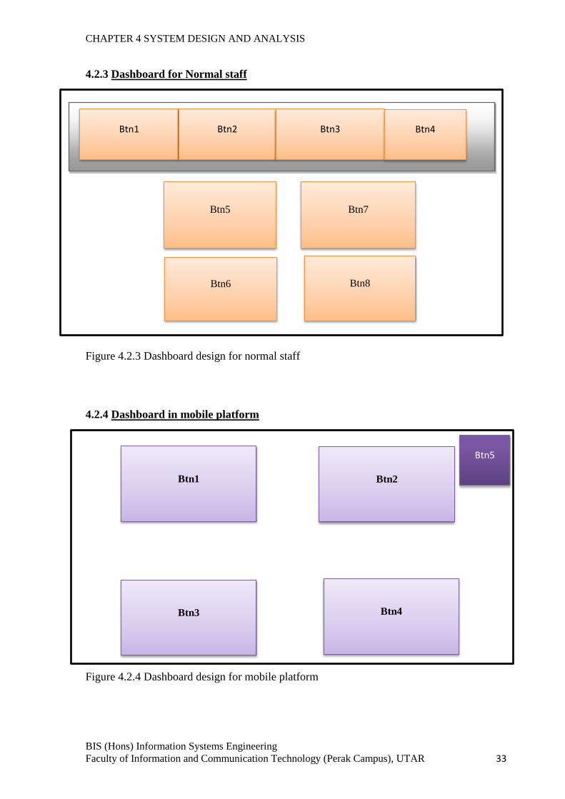
CHAPTER 4 SYSTEM DESIGN AND ANALYSIS
BIS (Hons) Information Systems Engineering
Faculty of Information and Communication Technology (Perak Campus), UTAR 33
4.2.3 Dashboard for Normal staff
Figure 4.2.3 Dashboard design for normal staff
4.2.4 Dashboard in mobile platform
Figure 4.2.4 Dashboard design for mobile platform
Btn5 Btn7
Btn1 Btn2 Btn3 Btn4
Btn6 Btn8
Btn1 Btn2
Btn5
Btn3 Btn4
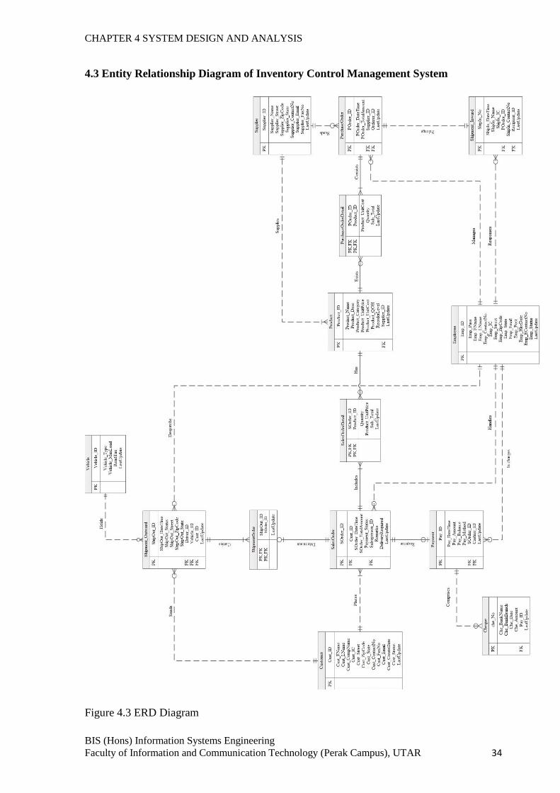
CHAPTER 4 SYSTEM DESIGN AND ANALYSIS
BIS (Hons) Information Systems Engineering
Faculty of Information and Communication Technology (Perak Campus), UTAR 34
4.3 Entity Relationship Diagram of Inventory Control Management System
Figure 4.3 ERD Diagram
CHAPTER 4 SYSTEM DESIGN AND ANALYSIS
BIS (Hons) Information Systems Engineering
Faculty of Information and Communication Technology (Perak Campus), UTAR 35
4.4 Business Rules
1. One customer can place many sales order.
2. Each sales order must place by one and only one customer.
3. One sales order can have zero or one shipment outward.
4. Each shipment outward only belongs to one and only one sales order.
5. One vehicle can hold zero or many shipment order.
6. Each shipment order only can hold by one vehicle.
7. One sales order can include many sales order details.
8. Each sales order details must belong to one and only one sales order.
9. Each sales order can have zero or one payment record.
10. Each payment must belong to one and only one sales order.
11. One payment can comprise with zero or many cheque.
12. Each cheque must form one and only one payment.
13. One product can be used in zero or many sales order detail.
14. Each sales order detail must have one and only one product.
15. One supplier can supply one or many product.
16. Each product only supplied by one and only one supplier.
17. One product can be exists in zero or many purchase order detail.
18. Each purchase order detail only exist one and only one product.
19. One purchase order can consist of one or many purchase order detail.
20. Each purchase order detail must belong to one and only one purchase order.
21. One supplier can receive zero or many purchase order.
22. Each purchase order must send to one and only one supplier.
23. One purchase order has one and only one shipment inward.
24. One shipment inward belongs to one and only one purchase order.
25. One employee can manages zero or many purchase order.
26. Each purchase order must managed by one employee.
27. One cashier can in charge zero or many payment.
28. Each payment must in charge by one and only one cashier.
29. One driver can dispatch zero or many shipment outward.
30. Each shipment outward must dispatch by one and only driver.
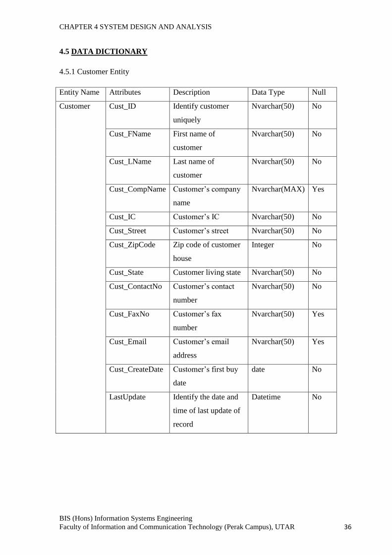
CHAPTER 4 SYSTEM DESIGN AND ANALYSIS
BIS (Hons) Information Systems Engineering
Faculty of Information and Communication Technology (Perak Campus), UTAR 36
4.5 DATA DICTIONARY
4.5.1 Customer Entity
Entity Name Attributes Description Data Type Null
Customer Cust_ID Identify customer
uniquely
Nvarchar(50) No
Cust_FName First name of
customer
Nvarchar(50) No
Cust_LName Last name of
customer
Nvarchar(50) No
Cust_CompName Customer’s company
name
Nvarchar(MAX) Yes
Cust_IC Customer’s IC Nvarchar(50) No
Cust_Street Customer’s street Nvarchar(50) No
Cust_ZipCode Zip code of customer
house
Integer No
Cust_State Customer living state Nvarchar(50) No
Cust_ContactNo Customer’s contact
number
Nvarchar(50) No
Cust_FaxNo Customer’s fax
number
Nvarchar(50) Yes
Cust_Email Customer’s email
address
Nvarchar(50) Yes
Cust_CreateDate Customer’s first buy
date
date No
LastUpdate Identify the date and
time of last update of
record
Datetime No
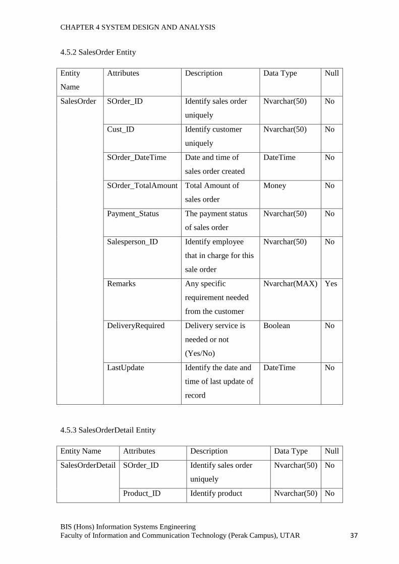
CHAPTER 4 SYSTEM DESIGN AND ANALYSIS
BIS (Hons) Information Systems Engineering
Faculty of Information and Communication Technology (Perak Campus), UTAR 37
4.5.2 SalesOrder Entity
Entity
Name
Attributes Description Data Type Null
SalesOrder SOrder_ID Identify sales order
uniquely
Nvarchar(50) No
Cust_ID Identify customer
uniquely
Nvarchar(50) No
SOrder_DateTime Date and time of
sales order created
DateTime No
SOrder_TotalAmount Total Amount of
sales order
Money No
Payment_Status The payment status
of sales order
Nvarchar(50) No
Salesperson_ID Identify employee
that in charge for this
sale order
Nvarchar(50) No
Remarks Any specific
requirement needed
from the customer
Nvarchar(MAX) Yes
DeliveryRequired Delivery service is
needed or not
(Yes/No)
Boolean No
LastUpdate Identify the date and
time of last update of
record
DateTime No
4.5.3 SalesOrderDetail Entity
Entity Name Attributes Description Data Type Null
SalesOrderDetail SOrder_ID Identify sales order
uniquely
Nvarchar(50) No
Product_ID Identify product Nvarchar(50) No
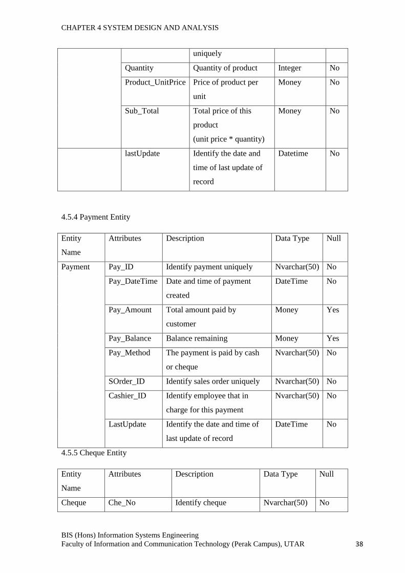
CHAPTER 4 SYSTEM DESIGN AND ANALYSIS
BIS (Hons) Information Systems Engineering
Faculty of Information and Communication Technology (Perak Campus), UTAR 38
uniquely
Quantity Quantity of product Integer No
Product_UnitPrice Price of product per
unit
Money No
Sub_Total Total price of this
product
(unit price * quantity)
Money No
lastUpdate Identify the date and
time of last update of
record
Datetime No
4.5.4 Payment Entity
Entity
Name
Attributes Description Data Type Null
Payment Pay_ID Identify payment uniquely Nvarchar(50) No
Pay_DateTime Date and time of payment
created
DateTime No
Pay_Amount Total amount paid by
customer
Money Yes
Pay_Balance Balance remaining Money Yes
Pay_Method The payment is paid by cash
or cheque
Nvarchar(50) No
SOrder_ID Identify sales order uniquely Nvarchar(50) No
Cashier_ID Identify employee that in
charge for this payment
Nvarchar(50) No
LastUpdate Identify the date and time of
last update of record
DateTime No
4.5.5 Cheque Entity
Entity
Name
Attributes Description Data Type Null
Cheque Che_No Identify cheque Nvarchar(50) No
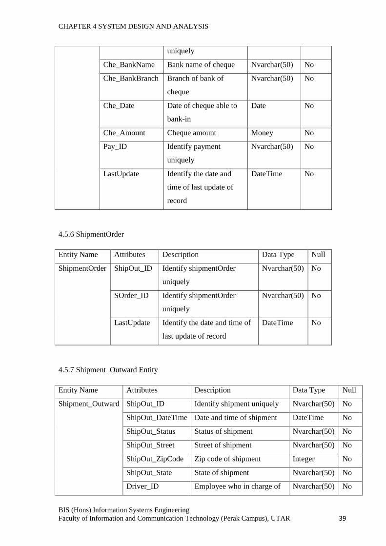
CHAPTER 4 SYSTEM DESIGN AND ANALYSIS
BIS (Hons) Information Systems Engineering
Faculty of Information and Communication Technology (Perak Campus), UTAR 39
uniquely
Che_BankName Bank name of cheque Nvarchar(50) No
Che_BankBranch Branch of bank of
cheque
Nvarchar(50) No
Che_Date Date of cheque able to
bank-in
Date No
Che_Amount Cheque amount Money No
Pay_ID Identify payment
uniquely
Nvarchar(50) No
LastUpdate Identify the date and
time of last update of
record
DateTime No
4.5.6 ShipmentOrder
Entity Name Attributes Description Data Type Null
ShipmentOrder ShipOut_ID Identify shipmentOrder
uniquely
Nvarchar(50) No
SOrder_ID Identify shipmentOrder
uniquely
Nvarchar(50) No
LastUpdate Identify the date and time of
last update of record
DateTime No
4.5.7 Shipment_Outward Entity
Entity Name Attributes Description Data Type Null
Shipment_Outward ShipOut_ID Identify shipment uniquely Nvarchar(50) No
ShipOut_DateTime Date and time of shipment DateTime No
ShipOut_Status Status of shipment Nvarchar(50) No
ShipOut_Street Street of shipment Nvarchar(50) No
ShipOut_ZipCode Zip code of shipment Integer No
ShipOut_State State of shipment Nvarchar(50) No
Driver_ID Employee who in charge of Nvarchar(50) No
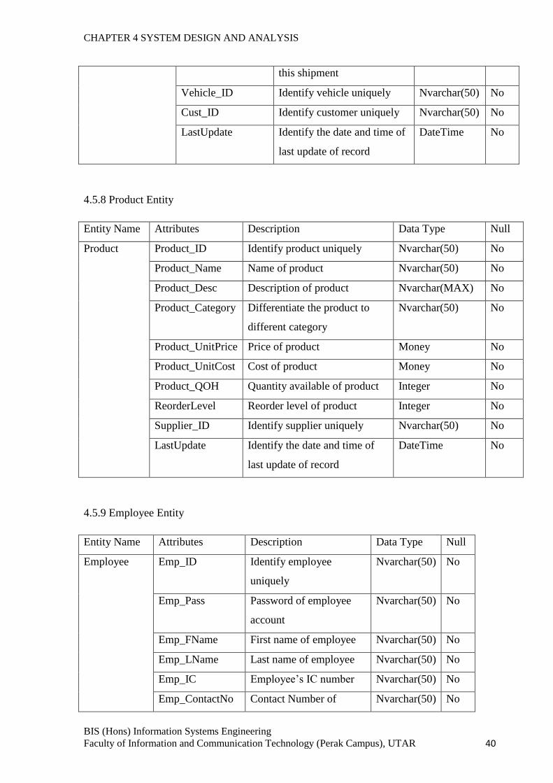
CHAPTER 4 SYSTEM DESIGN AND ANALYSIS
BIS (Hons) Information Systems Engineering
Faculty of Information and Communication Technology (Perak Campus), UTAR 40
this shipment
Vehicle_ID Identify vehicle uniquely Nvarchar(50) No
Cust_ID Identify customer uniquely Nvarchar(50) No
LastUpdate Identify the date and time of
last update of record
DateTime No
4.5.8 Product Entity
Entity Name Attributes Description Data Type Null
Product Product_ID Identify product uniquely Nvarchar(50) No
Product_Name Name of product Nvarchar(50) No
Product_Desc Description of product Nvarchar(MAX) No
Product_Category Differentiate the product to
different category
Nvarchar(50) No
Product_UnitPrice Price of product Money No
Product_UnitCost Cost of product Money No
Product_QOH Quantity available of product Integer No
ReorderLevel Reorder level of product Integer No
Supplier_ID Identify supplier uniquely Nvarchar(50) No
LastUpdate Identify the date and time of
last update of record
DateTime No
4.5.9 Employee Entity
Entity Name Attributes Description Data Type Null
Employee Emp_ID Identify employee
uniquely
Nvarchar(50) No
Emp_Pass Password of employee
account
Nvarchar(50) No
Emp_FName First name of employee Nvarchar(50) No
Emp_LName Last name of employee Nvarchar(50) No
Emp_IC Employee’s IC number Nvarchar(50) No
Emp_ContactNo Contact Number of Nvarchar(50) No
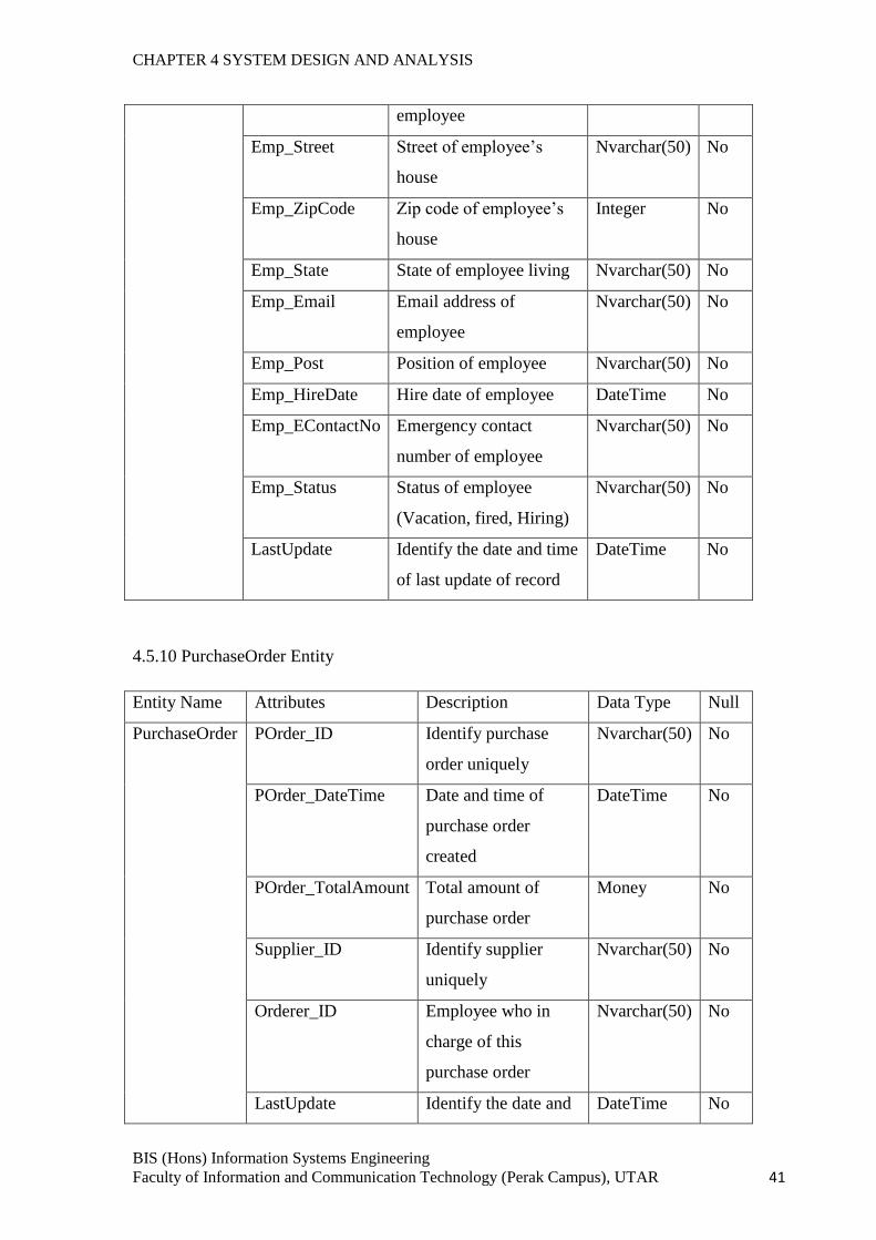
CHAPTER 4 SYSTEM DESIGN AND ANALYSIS
BIS (Hons) Information Systems Engineering
Faculty of Information and Communication Technology (Perak Campus), UTAR 41
employee
Emp_Street Street of employee’s
house
Nvarchar(50) No
Emp_ZipCode Zip code of employee’s
house
Integer No
Emp_State State of employee living Nvarchar(50) No
Emp_Email Email address of
employee
Nvarchar(50) No
Emp_Post Position of employee Nvarchar(50) No
Emp_HireDate Hire date of employee DateTime No
Emp_EContactNo Emergency contact
number of employee
Nvarchar(50) No
Emp_Status Status of employee
(Vacation, fired, Hiring)
Nvarchar(50) No
LastUpdate Identify the date and time
of last update of record
DateTime No
4.5.10 PurchaseOrder Entity
Entity Name Attributes Description Data Type Null
PurchaseOrder POrder_ID Identify purchase
order uniquely
Nvarchar(50) No
POrder_DateTime Date and time of
purchase order
created
DateTime No
POrder_TotalAmount Total amount of
purchase order
Money No
Supplier_ID Identify supplier
uniquely
Nvarchar(50) No
Orderer_ID Employee who in
charge of this
purchase order
Nvarchar(50) No
LastUpdate Identify the date and DateTime No
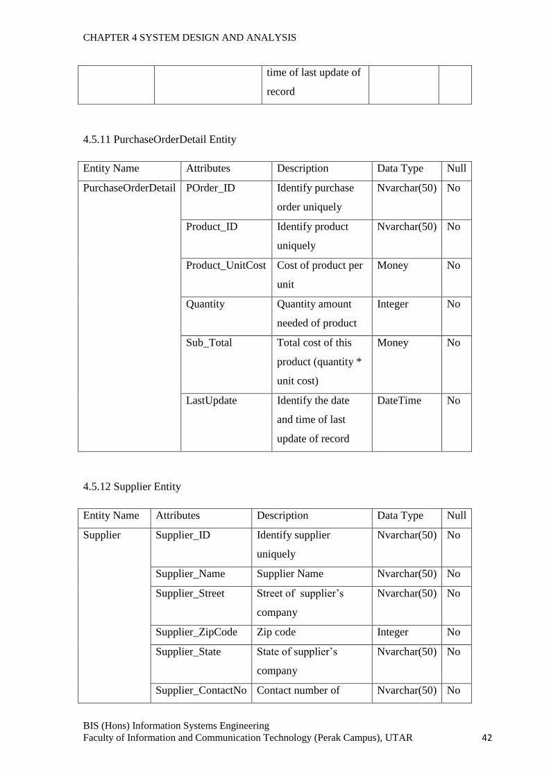
CHAPTER 4 SYSTEM DESIGN AND ANALYSIS
BIS (Hons) Information Systems Engineering
Faculty of Information and Communication Technology (Perak Campus), UTAR 42
time of last update of
record
4.5.11 PurchaseOrderDetail Entity
Entity Name Attributes Description Data Type Null
PurchaseOrderDetail POrder_ID Identify purchase
order uniquely
Nvarchar(50) No
Product_ID Identify product
uniquely
Nvarchar(50) No
Product_UnitCost Cost of product per
unit
Money No
Quantity Quantity amount
needed of product
Integer No
Sub_Total Total cost of this
product (quantity *
unit cost)
Money No
LastUpdate Identify the date
and time of last
update of record
DateTime No
4.5.12 Supplier Entity
Entity Name Attributes Description Data Type Null
Supplier Supplier_ID Identify supplier
uniquely
Nvarchar(50) No
Supplier_Name Supplier Name Nvarchar(50) No
Supplier_Street Street of supplier’s
company
Nvarchar(50) No
Supplier_ZipCode Zip code Integer No
Supplier_State State of supplier’s
company
Nvarchar(50) No
Supplier_ContactNo Contact number of Nvarchar(50) No
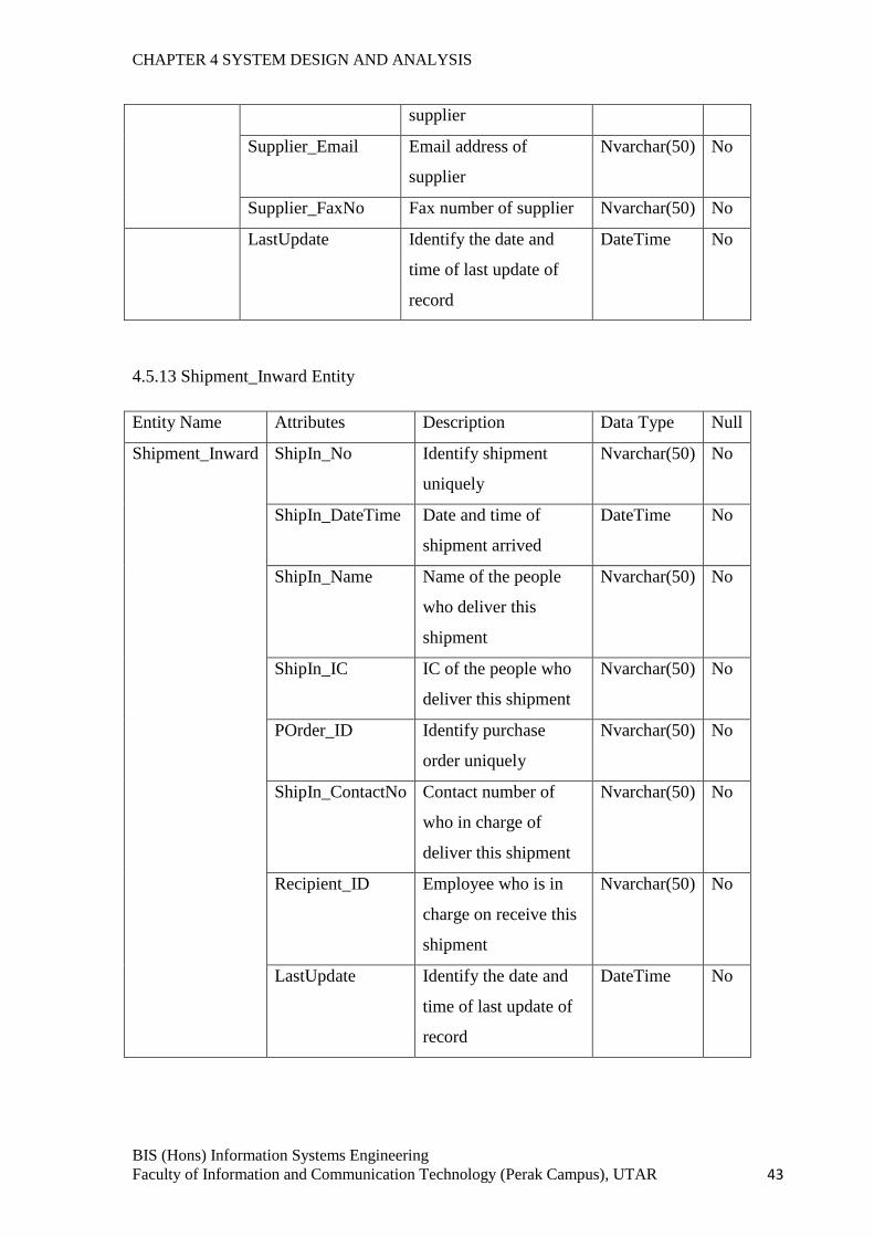
CHAPTER 4 SYSTEM DESIGN AND ANALYSIS
BIS (Hons) Information Systems Engineering
Faculty of Information and Communication Technology (Perak Campus), UTAR 43
supplier
Supplier_Email Email address of
supplier
Nvarchar(50) No
Supplier_FaxNo Fax number of supplier Nvarchar(50) No
LastUpdate Identify the date and
time of last update of
record
DateTime No
4.5.13 Shipment_Inward Entity
Entity Name Attributes Description Data Type Null
Shipment_Inward ShipIn_No Identify shipment
uniquely
Nvarchar(50) No
ShipIn_DateTime Date and time of
shipment arrived
DateTime No
ShipIn_Name Name of the people
who deliver this
shipment
Nvarchar(50) No
ShipIn_IC IC of the people who
deliver this shipment
Nvarchar(50) No
POrder_ID Identify purchase
order uniquely
Nvarchar(50) No
ShipIn_ContactNo Contact number of
who in charge of
deliver this shipment
Nvarchar(50) No
Recipient_ID Employee who is in
charge on receive this
shipment
Nvarchar(50) No
LastUpdate Identify the date and
time of last update of
record
DateTime No
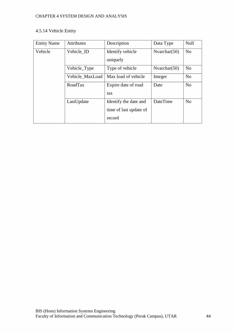
CHAPTER 4 SYSTEM DESIGN AND ANALYSIS
BIS (Hons) Information Systems Engineering
Faculty of Information and Communication Technology (Perak Campus), UTAR 44
4.5.14 Vehicle Entity
Entity Name Attributes Description Data Type Null
Vehicle Vehicle_ID Identify vehicle
uniquely
Nvarchar(50) No
Vehicle_Type Type of vehicle Nvarchar(50) No
Vehicle_MaxLoad Max load of vehicle Integer No
RoadTax Expire date of road
tax
Date No
LastUpdate Identify the date and
time of last update of
record
DateTime No
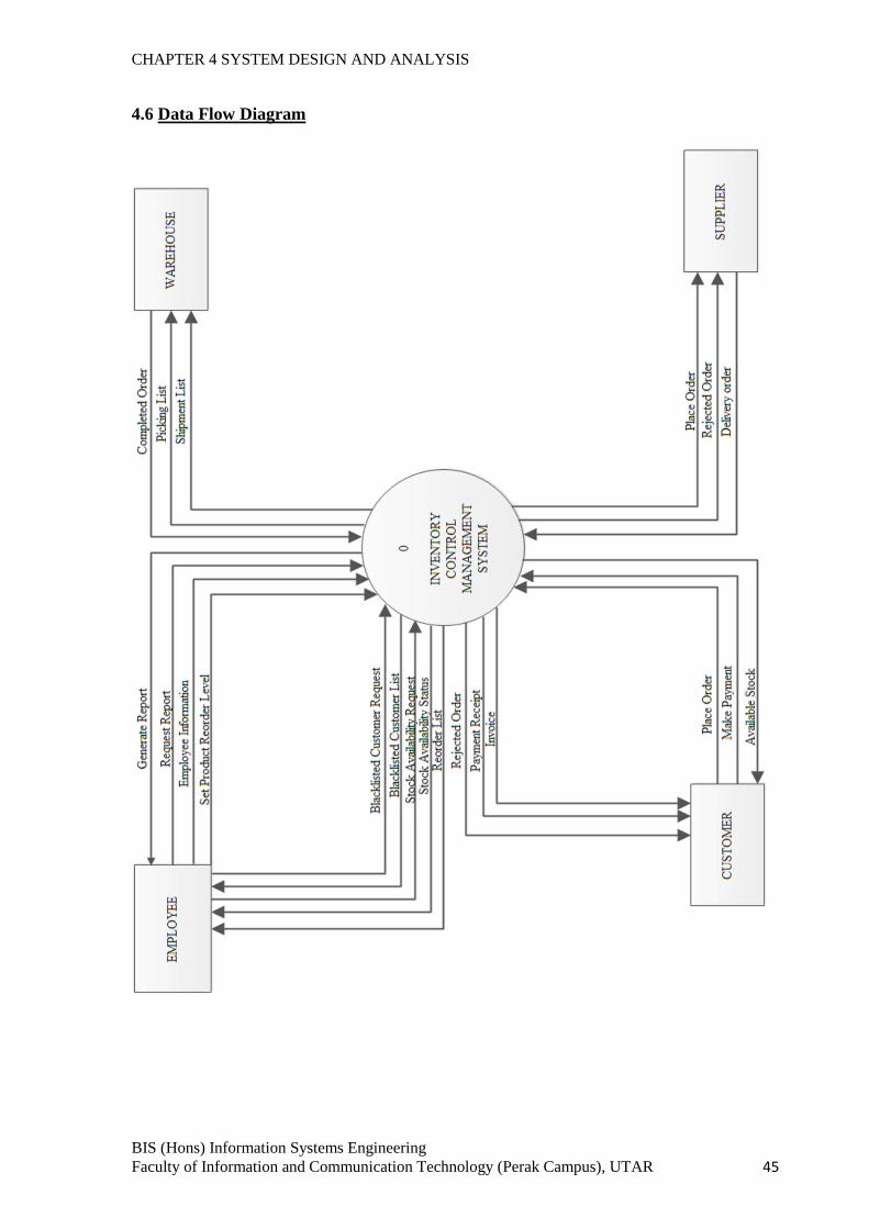
CHAPTER 4 SYSTEM DESIGN AND ANALYSIS
BIS (Hons) Information Systems Engineering
Faculty of Information and Communication Technology (Perak Campus), UTAR 45
4.6 Data Flow Diagram
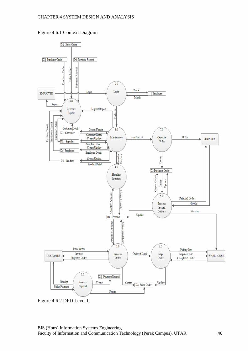
CHAPTER 4 SYSTEM DESIGN AND ANALYSIS
BIS (Hons) Information Systems Engineering
Faculty of Information and Communication Technology (Perak Campus), UTAR 46
Figure 4.6.1 Context Diagram
Figure 4.6.2 DFD Level 0
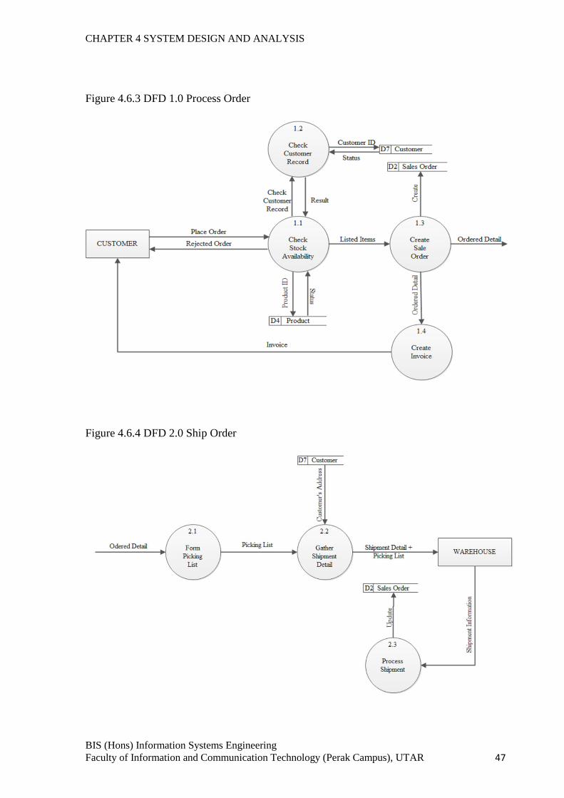
CHAPTER 4 SYSTEM DESIGN AND ANALYSIS
BIS (Hons) Information Systems Engineering
Faculty of Information and Communication Technology (Perak Campus), UTAR 47
Figure 4.6.3 DFD 1.0 Process Order
Figure 4.6.4 DFD 2.0 Ship Order
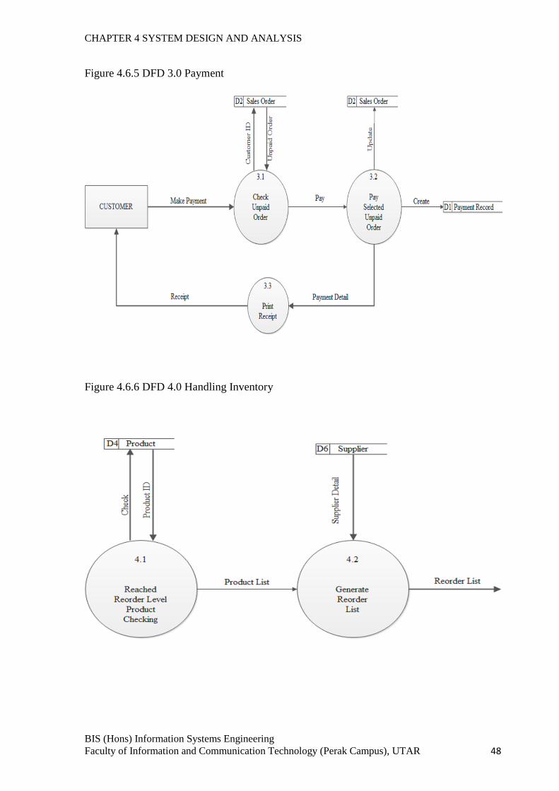
CHAPTER 4 SYSTEM DESIGN AND ANALYSIS
BIS (Hons) Information Systems Engineering
Faculty of Information and Communication Technology (Perak Campus), UTAR 48
Figure 4.6.5 DFD 3.0 Payment
Figure 4.6.6 DFD 4.0 Handling Inventory
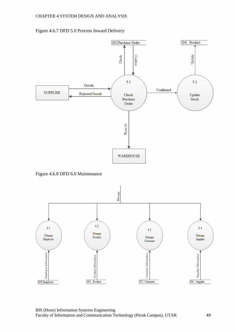
CHAPTER 4 SYSTEM DESIGN AND ANALYSIS
BIS (Hons) Information Systems Engineering
Faculty of Information and Communication Technology (Perak Campus), UTAR 49
Figure 4.6.7 DFD 5.0 Process Inward Delivery
Figure 4.6.8 DFD 6.0 Maintenance
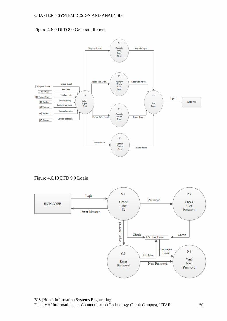
CHAPTER 4 SYSTEM DESIGN AND ANALYSIS
BIS (Hons) Information Systems Engineering
Faculty of Information and Communication Technology (Perak Campus), UTAR 50
Figure 4.6.9 DFD 8.0 Generate Report
Figure 4.6.10 DFD 9.0 Login
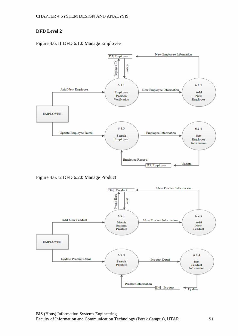
CHAPTER 4 SYSTEM DESIGN AND ANALYSIS
BIS (Hons) Information Systems Engineering
Faculty of Information and Communication Technology (Perak Campus), UTAR 51
DFD Level 2
Figure 4.6.11 DFD 6.1.0 Manage Employee
Figure 4.6.12 DFD 6.2.0 Manage Product
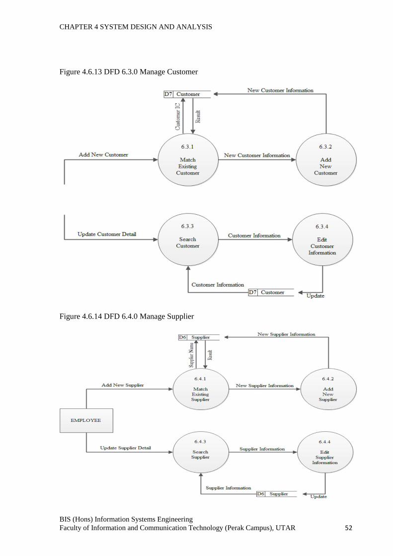
CHAPTER 4 SYSTEM DESIGN AND ANALYSIS
BIS (Hons) Information Systems Engineering
Faculty of Information and Communication Technology (Perak Campus), UTAR 52
Figure 4.6.13 DFD 6.3.0 Manage Customer
Figure 4.6.14 DFD 6.4.0 Manage Supplier
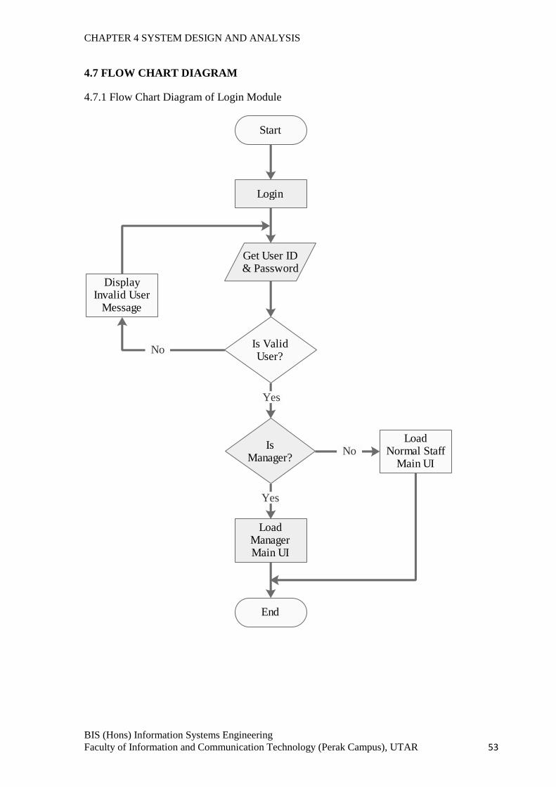
CHAPTER 4 SYSTEM DESIGN AND ANALYSIS
BIS (Hons) Information Systems Engineering
Faculty of Information and Communication Technology (Perak Campus), UTAR 53
4.7 FLOW CHART DIAGRAM
4.7.1 Flow Chart Diagram of Login Module
Start
Login
Is Valid User?
Get User ID & Password
Display Invalid User
Message
Is Manager?
Load Manager Main UI
Load Normal Staff
Main UI
End
No
Yes
No
Yes
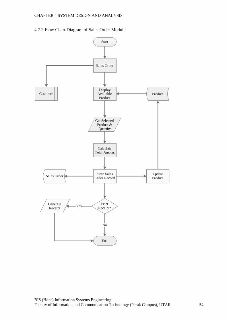
CHAPTER 4 SYSTEM DESIGN AND ANALYSIS
BIS (Hons) Information Systems Engineering
Faculty of Information and Communication Technology (Perak Campus), UTAR 54
4.7.2 Flow Chart Diagram of Sales Order Module
Start
Sales Order
Display Available Product
End
Get Selected Product & Quantity
Calculate Total Amount
Customer
Print Receipt?
Product
Generate Receipt
Yes
No
Store Sales Order Record
Sales OrderUpdate Product
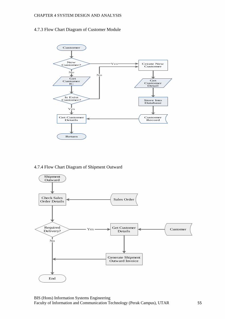
CHAPTER 4 SYSTEM DESIGN AND ANALYSIS
BIS (Hons) Information Systems Engineering
Faculty of Information and Communication Technology (Perak Campus), UTAR 55
4.7.3 Flow Chart Diagram of Customer Module
4.7.4 Flow Chart Diagram of Shipment Outward
Customer
Return
New Customer?
Get Customer
IC
Is Exist Customer?
Get Customer Details
Get Customer
Detail
Create New Customer
No
Store Into Database
Yes
Yes
No
CustomerRecord
ShipmentOutward
Check Sales Order Details
Required Delivery?
Sales Order
End
Get Customer Details
Customer
Generate Shipment Outward Invoice
No
Yes
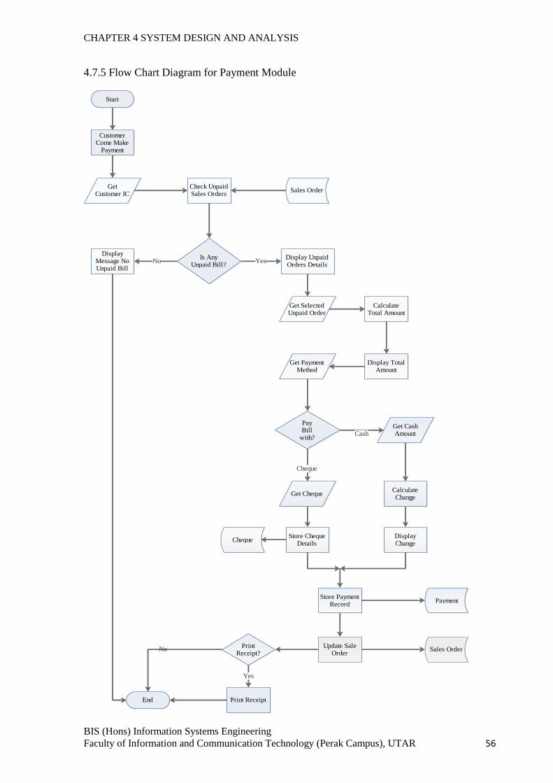
CHAPTER 4 SYSTEM DESIGN AND ANALYSIS
BIS (Hons) Information Systems Engineering
Faculty of Information and Communication Technology (Perak Campus), UTAR 56
4.7.5 Flow Chart Diagram for Payment Module
Start
Customer Come Make
Payment
GetCustomer IC
Check Unpaid Sales Orders
Sales Order
Is Any Unpaid Bill?
End
Display Unpaid Orders Details
Get Selected Unpaid Order
Calculate Total Amount
Display Total Amount
Get Payment Method
Pay Bill
with?
Get Cash Amount
Calculate Change
Display Change
Get Cheque
Store Cheque Details
Store Payment Record
Payment
Cheque
Print Receipt?
Print Receipt
YesDisplay
Message No Unpaid Bill
Cash
Cheque
Yes
No
No
Update Sale Order
Sales Order
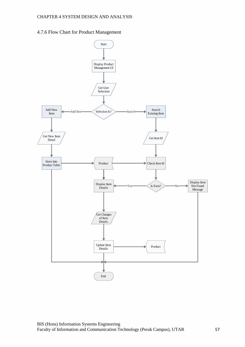
CHAPTER 4 SYSTEM DESIGN AND ANALYSIS
BIS (Hons) Information Systems Engineering
Faculty of Information and Communication Technology (Perak Campus), UTAR 57
4.7.6 Flow Chart for Product Management
Start
Selection Is?Add New
ItemSearch
Existing Item
Display Product Management UI
Get User Selection
Get New Item Detail
Get Item Id
Store Into Product Table
Product Check Item Id
Is Exist?
Add Item Search
Display Item Not Found Message
NoDisplay Item
DetailsYes
Get Changes of Item Details
Update Item Details
Product
End
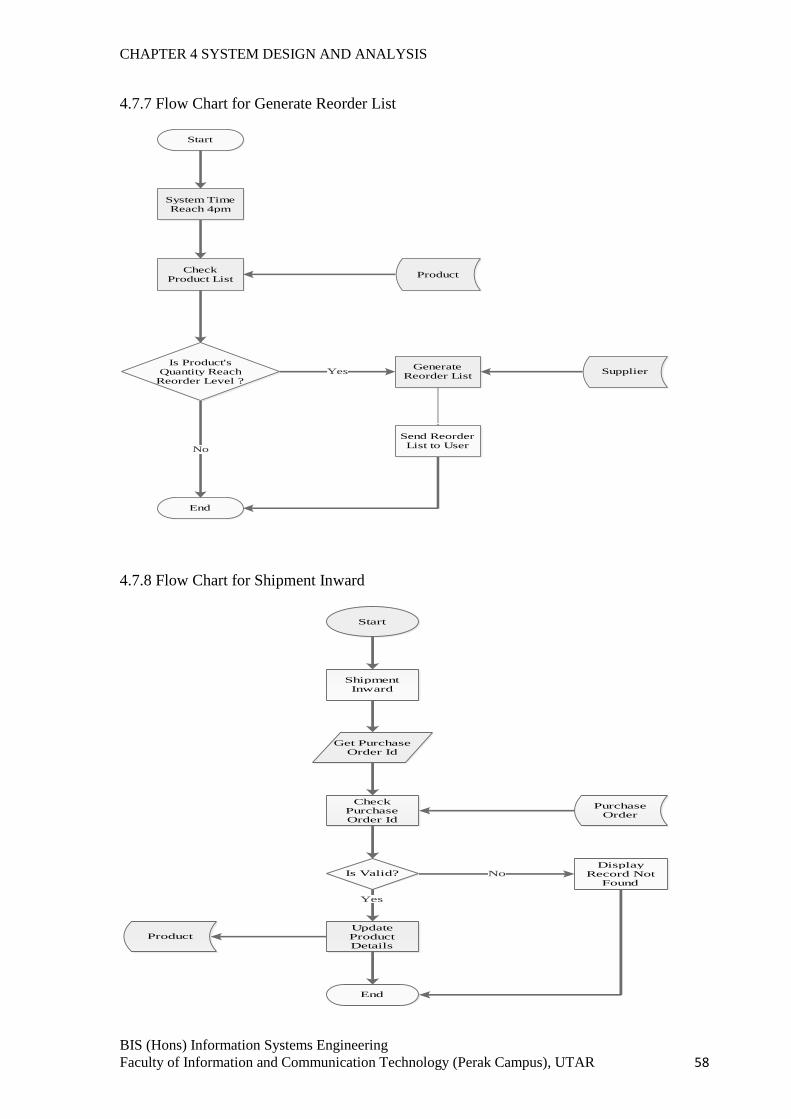
CHAPTER 4 SYSTEM DESIGN AND ANALYSIS
BIS (Hons) Information Systems Engineering
Faculty of Information and Communication Technology (Perak Campus), UTAR 58
4.7.7 Flow Chart for Generate Reorder List
4.7.8 Flow Chart for Shipment Inward
Start
System Time Reach 4pm
Check Product List
Product
Is Product's Quantity Reach
Reorder Level ?
End
Generate Reorder List
Supplier
No
Yes
Send Reorder List to User
Start
Shipment Inward
Get Purchase Order Id
Is Valid?
Check Purchase Order Id
Purchase Order
Display Record Not
Found
Update Product Details
Product
End
No
Yes
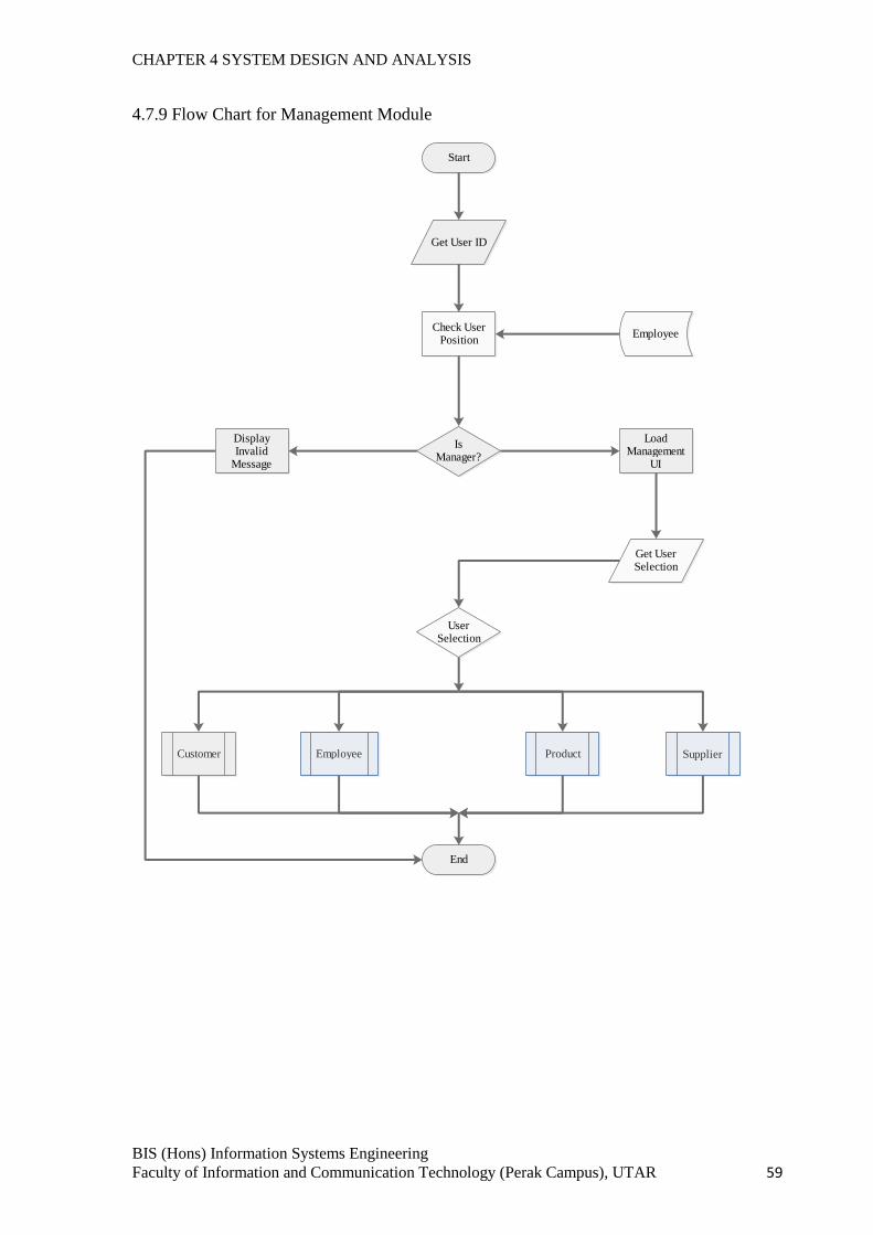
CHAPTER 4 SYSTEM DESIGN AND ANALYSIS
BIS (Hons) Information Systems Engineering
Faculty of Information and Communication Technology (Perak Campus), UTAR 59
4.7.9 Flow Chart for Management Module
Start
Get User ID
Check User Position
Employee
Is Manager?
Display Invalid
Message
Load Management
UI
Get User Selection
User Selection
Customer Employee Product Supplier
End
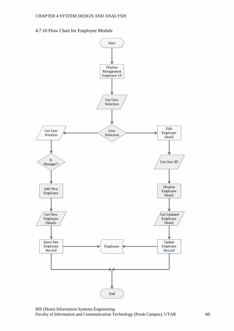
CHAPTER 4 SYSTEM DESIGN AND ANALYSIS
BIS (Hons) Information Systems Engineering
Faculty of Information and Communication Technology (Perak Campus), UTAR 60
4.7.10 Flow Chart for Employee Module
Start
Display Management Employee UI
Get User Selection
User Selection
Add New Employee
Edit Employee
Detail
Get User Position
Is Manager?
Get New Employee
Details
Insert Into Employee
RecordEmployee
End
Get User ID
Display Employee
Detail
Get Updated Employee
Detail
Update Employee
Record
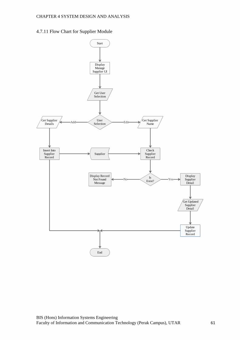
CHAPTER 4 SYSTEM DESIGN AND ANALYSIS
BIS (Hons) Information Systems Engineering
Faculty of Information and Communication Technology (Perak Campus), UTAR 61
4.7.11 Flow Chart for Supplier Module
Start
Display Manage
Supplier UI
Get User Selection
User Selection
Get Supplier Details
Insert Into Supplier Record
Supplier
Get Supplier Name
Check Supplier Record
Is Exist?
Display Supplier Detail
Get Updated Supplier Detail
Update Supplier Record
Display Record Not Found Message
End
Add Edit
No Yes
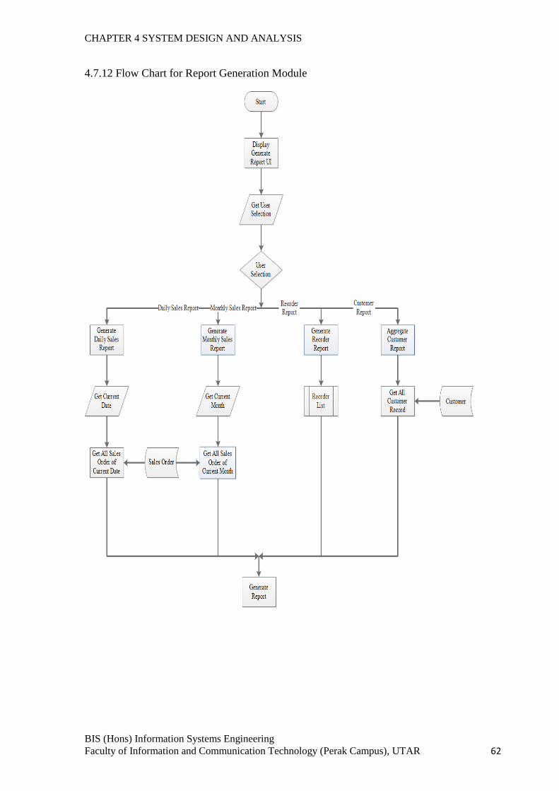
CHAPTER 4 SYSTEM DESIGN AND ANALYSIS
BIS (Hons) Information Systems Engineering
Faculty of Information and Communication Technology (Perak Campus), UTAR 62
4.7.12 Flow Chart for Report Generation Module
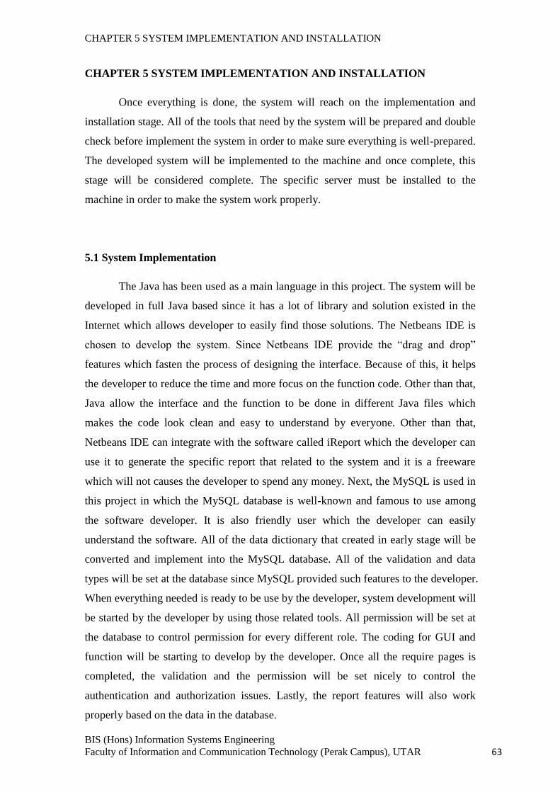
CHAPTER 5 SYSTEM IMPLEMENTATION AND INSTALLATION
BIS (Hons) Information Systems Engineering
Faculty of Information and Communication Technology (Perak Campus), UTAR 63
CHAPTER 5 SYSTEM IMPLEMENTATION AND INSTALLATION
Once everything is done, the system will reach on the implementation and
installation stage. All of the tools that need by the system will be prepared and double
check before implement the system in order to make sure everything is well-prepared.
The developed system will be implemented to the machine and once complete, this
stage will be considered complete. The specific server must be installed to the
machine in order to make the system work properly.
5.1 System Implementation
The Java has been used as a main language in this project. The system will be
developed in full Java based since it has a lot of library and solution existed in the
Internet which allows developer to easily find those solutions. The Netbeans IDE is
chosen to develop the system. Since Netbeans IDE provide the “drag and drop”
features which fasten the process of designing the interface. Because of this, it helps
the developer to reduce the time and more focus on the function code. Other than that,
Java allow the interface and the function to be done in different Java files which
makes the code look clean and easy to understand by everyone. Other than that,
Netbeans IDE can integrate with the software called iReport which the developer can
use it to generate the specific report that related to the system and it is a freeware
which will not causes the developer to spend any money. Next, the MySQL is used in
this project in which the MySQL database is well-known and famous to use among
the software developer. It is also friendly user which the developer can easily
understand the software. All of the data dictionary that created in early stage will be
converted and implement into the MySQL database. All of the validation and data
types will be set at the database since MySQL provided such features to the developer.
When everything needed is ready to be use by the developer, system development will
be started by the developer by using those related tools. All permission will be set at
the database to control permission for every different role. The coding for GUI and
function will be starting to develop by the developer. Once all the require pages is
completed, the validation and the permission will be set nicely to control the
authentication and authorization issues. Lastly, the report features will also work
properly based on the data in the database.
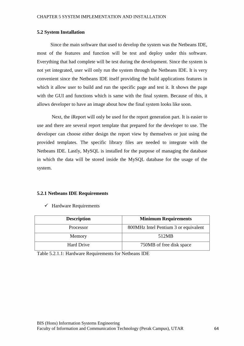
CHAPTER 5 SYSTEM IMPLEMENTATION AND INSTALLATION
BIS (Hons) Information Systems Engineering
Faculty of Information and Communication Technology (Perak Campus), UTAR 64
5.2 System Installation
Since the main software that used to develop the system was the Netbeans IDE,
most of the features and function will be test and deploy under this software.
Everything that had complete will be test during the development. Since the system is
not yet integrated, user will only run the system through the Netbeans IDE. It is very
convenient since the Netbeans IDE itself providing the build applications features in
which it allow user to build and run the specific page and test it. It shows the page
with the GUI and functions which is same with the final system. Because of this, it
allows developer to have an image about how the final system looks like soon.
Next, the iReport will only be used for the report generation part. It is easier to
use and there are several report template that prepared for the developer to use. The
developer can choose either design the report view by themselves or just using the
provided templates. The specific library files are needed to integrate with the
Netbeans IDE. Lastly, MySQL is installed for the purpose of managing the database
in which the data will be stored inside the MySQL database for the usage of the
system.
5.2.1 Netbeans IDE Requirements
Hardware Requirements
Description Minimum Requirements
Processor 800MHz Intel Pentium 3 or equivalent
Memory 512MB
Hard Drive 750MB of free disk space
Table 5.2.1.1: Hardware Requirements for Netbeans IDE
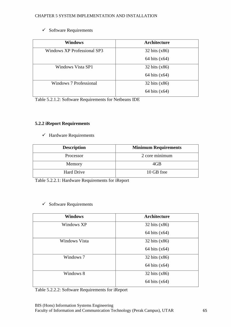
CHAPTER 5 SYSTEM IMPLEMENTATION AND INSTALLATION
BIS (Hons) Information Systems Engineering
Faculty of Information and Communication Technology (Perak Campus), UTAR 65
Software Requirements
Windows Architecture
Windows XP Professional SP3 32 bits (x86)
64 bits (x64)
Windows Vista SP1 32 bits (x86)
64 bits (x64)
Windows 7 Professional 32 bits (x86)
64 bits (x64)
Table 5.2.1.2: Software Requirements for Netbeans IDE
5.2.2 iReport Requirements
Hardware Requirements
Description Minimum Requirements
Processor 2 core minimum
Memory 4GB
Hard Drive 10 GB free
Table 5.2.2.1: Hardware Requirements for iReport
Software Requirements
Windows Architecture
Windows XP 32 bits (x86)
64 bits (x64)
Windows Vista 32 bits (x86)
64 bits (x64)
Windows 7 32 bits (x86)
64 bits (x64)
Windows 8 32 bits (x86)
64 bits (x64)
Table 5.2.2.2: Software Requirements for iReport
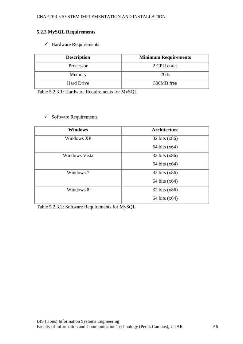
CHAPTER 5 SYSTEM IMPLEMENTATION AND INSTALLATION
BIS (Hons) Information Systems Engineering
Faculty of Information and Communication Technology (Perak Campus), UTAR 66
5.2.3 MySQL Requirements
Hardware Requirements
Description Minimum Requirements
Processor 2 CPU cores
Memory 2GB
Hard Drive 500MB free
Table 5.2.3.1: Hardware Requirements for MySQL
Software Requirements
Windows Architecture
Windows XP 32 bits (x86)
64 bits (x64)
Windows Vista 32 bits (x86)
64 bits (x64)
Windows 7 32 bits (x86)
64 bits (x64)
Windows 8 32 bits (x86)
64 bits (x64)
Table 5.2.3.2: Software Requirements for MySQL
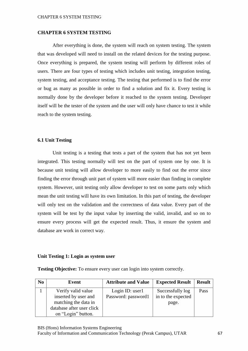
CHAPTER 6 SYSTEM TESTING
BIS (Hons) Information Systems Engineering
Faculty of Information and Communication Technology (Perak Campus), UTAR 67
CHAPTER 6 SYSTEM TESTING
After everything is done, the system will reach on system testing. The system
that was developed will need to install on the related devices for the testing purpose.
Once everything is prepared, the system testing will perform by different roles of
users. There are four types of testing which includes unit testing, integration testing,
system testing, and acceptance testing. The testing that performed is to find the error
or bug as many as possible in order to find a solution and fix it. Every testing is
normally done by the developer before it reached to the system testing. Developer
itself will be the tester of the system and the user will only have chance to test it while
reach to the system testing.
6.1 Unit Testing
Unit testing is a testing that tests a part of the system that has not yet been
integrated. This testing normally will test on the part of system one by one. It is
because unit testing will allow developer to more easily to find out the error since
finding the error through unit part of system will more easier than finding in complete
system. However, unit testing only allow developer to test on some parts only which
mean the unit testing will have its own limitation. In this part of testing, the developer
will only test on the validation and the correctness of data value. Every part of the
system will be test by the input value by inserting the valid, invalid, and so on to
ensure every process will get the expected result. Thus, it ensure the system and
database are work in correct way.
Unit Testing 1: Login as system user
Testing Objective: To ensure every user can login into system correctly.
No Event Attribute and Value Expected Result Result
1 Verify valid value
inserted by user and
matching the data in
database after user click
on “Login” button.
Login ID: user1
Password: password1
Successfully log
in to the expected
page.
Pass
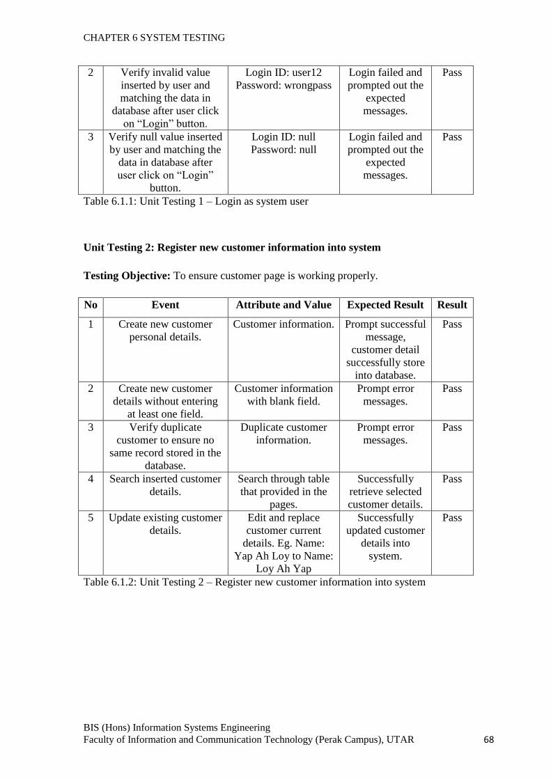
CHAPTER 6 SYSTEM TESTING
BIS (Hons) Information Systems Engineering
Faculty of Information and Communication Technology (Perak Campus), UTAR 68
2 Verify invalid value
inserted by user and
matching the data in
database after user click
on “Login” button.
Login ID: user12
Password: wrongpass
Login failed and
prompted out the
expected
messages.
Pass
3 Verify null value inserted
by user and matching the
data in database after
user click on “Login”
button.
Login ID: null
Password: null
Login failed and
prompted out the
expected
messages.
Pass
Table 6.1.1: Unit Testing 1 – Login as system user
Unit Testing 2: Register new customer information into system
Testing Objective: To ensure customer page is working properly.
No Event Attribute and Value Expected Result Result
1 Create new customer
personal details.
Customer information. Prompt successful
message,
customer detail
successfully store
into database.
Pass
2 Create new customer
details without entering
at least one field.
Customer information
with blank field.
Prompt error
messages.
Pass
3 Verify duplicate
customer to ensure no
same record stored in the
database.
Duplicate customer
information.
Prompt error
messages.
Pass
4 Search inserted customer
details.
Search through table
that provided in the
pages.
Successfully
retrieve selected
customer details.
Pass
5 Update existing customer
details.
Edit and replace
customer current
details. Eg. Name:
Yap Ah Loy to Name:
Loy Ah Yap
Successfully
updated customer
details into
system.
Pass
Table 6.1.2: Unit Testing 2 – Register new customer information into system
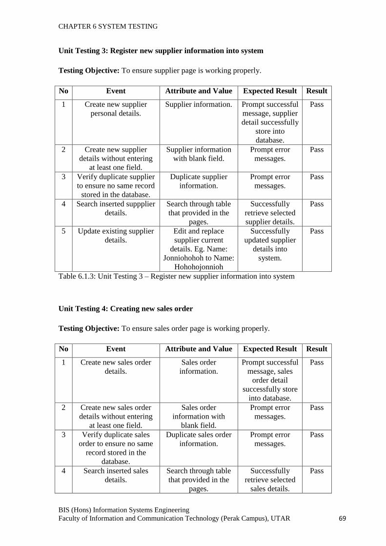
CHAPTER 6 SYSTEM TESTING
BIS (Hons) Information Systems Engineering
Faculty of Information and Communication Technology (Perak Campus), UTAR 69
Unit Testing 3: Register new supplier information into system
Testing Objective: To ensure supplier page is working properly.
No Event Attribute and Value Expected Result Result
1 Create new supplier
personal details.
Supplier information. Prompt successful
message, supplier
detail successfully
store into
database.
Pass
2 Create new supplier
details without entering
at least one field.
Supplier information
with blank field.
Prompt error
messages.
Pass
3 Verify duplicate supplier
to ensure no same record
stored in the database.
Duplicate supplier
information.
Prompt error
messages.
Pass
4 Search inserted suppplier
details.
Search through table
that provided in the
pages.
Successfully
retrieve selected
supplier details.
Pass
5 Update existing supplier
details.
Edit and replace
supplier current
details. Eg. Name:
Jonniohohoh to Name:
Hohohojonnioh
Successfully
updated supplier
details into
system.
Pass
Table 6.1.3: Unit Testing 3 – Register new supplier information into system
Unit Testing 4: Creating new sales order
Testing Objective: To ensure sales order page is working properly.
No Event Attribute and Value Expected Result Result
1 Create new sales order
details.
Sales order
information.
Prompt successful
message, sales
order detail
successfully store
into database.
Pass
2 Create new sales order
details without entering
at least one field.
Sales order
information with
blank field.
Prompt error
messages.
Pass
3 Verify duplicate sales
order to ensure no same
record stored in the
database.
Duplicate sales order
information.
Prompt error
messages.
Pass
4 Search inserted sales
details.
Search through table
that provided in the
pages.
Successfully
retrieve selected
sales details.
Pass
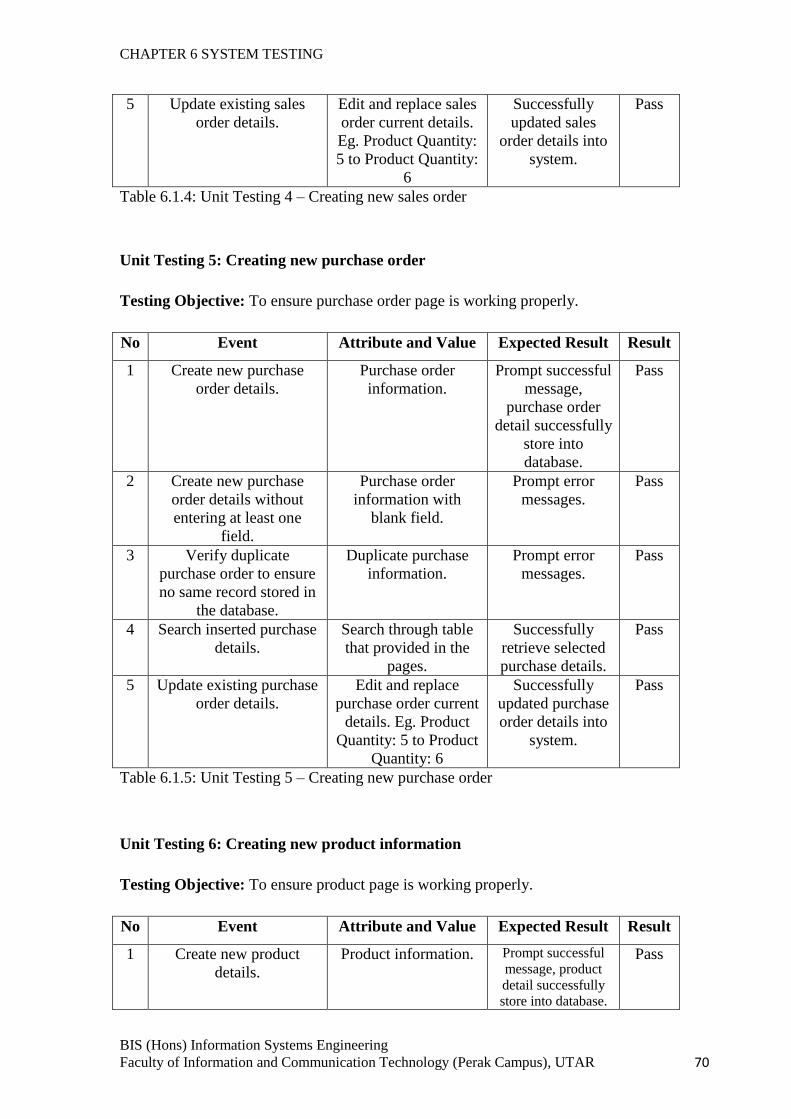
CHAPTER 6 SYSTEM TESTING
BIS (Hons) Information Systems Engineering
Faculty of Information and Communication Technology (Perak Campus), UTAR 70
5 Update existing sales
order details.
Edit and replace sales
order current details.
Eg. Product Quantity:
5 to Product Quantity:
6
Successfully
updated sales
order details into
system.
Pass
Table 6.1.4: Unit Testing 4 – Creating new sales order
Unit Testing 5: Creating new purchase order
Testing Objective: To ensure purchase order page is working properly.
No Event Attribute and Value Expected Result Result
1 Create new purchase
order details.
Purchase order
information.
Prompt successful
message,
purchase order
detail successfully
store into
database.
Pass
2 Create new purchase
order details without
entering at least one
field.
Purchase order
information with
blank field.
Prompt error
messages.
Pass
3 Verify duplicate
purchase order to ensure
no same record stored in
the database.
Duplicate purchase
information.
Prompt error
messages.
Pass
4 Search inserted purchase
details.
Search through table
that provided in the
pages.
Successfully
retrieve selected
purchase details.
Pass
5 Update existing purchase
order details.
Edit and replace
purchase order current
details. Eg. Product
Quantity: 5 to Product
Quantity: 6
Successfully
updated purchase
order details into
system.
Pass
Table 6.1.5: Unit Testing 5 – Creating new purchase order
Unit Testing 6: Creating new product information
Testing Objective: To ensure product page is working properly.
No Event Attribute and Value Expected Result Result
1 Create new product
details.
Product information. Prompt successful
message, product
detail successfully
store into database.
Pass
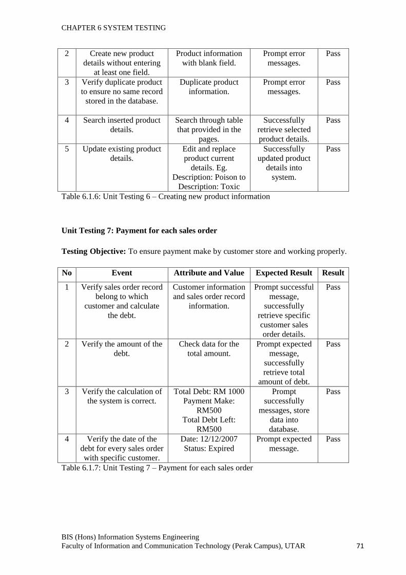
CHAPTER 6 SYSTEM TESTING
BIS (Hons) Information Systems Engineering
Faculty of Information and Communication Technology (Perak Campus), UTAR 71
2 Create new product
details without entering
at least one field.
Product information
with blank field.
Prompt error
messages.
Pass
3 Verify duplicate product
to ensure no same record
stored in the database.
Duplicate product
information.
Prompt error
messages.
Pass
4 Search inserted product
details.
Search through table
that provided in the
pages.
Successfully
retrieve selected
product details.
Pass
5 Update existing product
details.
Edit and replace
product current
details. Eg.
Description: Poison to
Description: Toxic
Successfully
updated product
details into
system.
Pass
Table 6.1.6: Unit Testing 6 – Creating new product information
Unit Testing 7: Payment for each sales order
Testing Objective: To ensure payment make by customer store and working properly.
No Event Attribute and Value Expected Result Result
1 Verify sales order record
belong to which
customer and calculate
the debt.
Customer information
and sales order record
information.
Prompt successful
message,
successfully
retrieve specific
customer sales
order details.
Pass
2 Verify the amount of the
debt.
Check data for the
total amount.
Prompt expected
message,
successfully
retrieve total
amount of debt.
Pass
3 Verify the calculation of
the system is correct.
Total Debt: RM 1000
Payment Make:
RM500
Total Debt Left:
RM500
Prompt
successfully
messages, store
data into
database.
Pass
4 Verify the date of the
debt for every sales order
with specific customer.
Date: 12/12/2007
Status: Expired
Prompt expected
message.
Pass
Table 6.1.7: Unit Testing 7 – Payment for each sales order
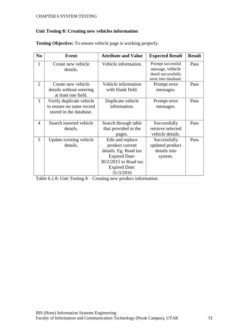
CHAPTER 6 SYSTEM TESTING
BIS (Hons) Information Systems Engineering
Faculty of Information and Communication Technology (Perak Campus), UTAR 72
Unit Testing 8: Creating new vehicles information
Testing Objective: To ensure vehicle page is working properly.
No Event Attribute and Value Expected Result Result
1 Create new vehicle
details.
Vehicle information. Prompt successful
message, vehicle
detail successfully
store into database.
Pass
2 Create new vehicle
details without entering
at least one field.
Vehicle information
with blank field.
Prompt error
messages.
Pass
3 Verify duplicate vehicle
to ensure no same record
stored in the database.
Duplicate vehicle
information.
Prompt error
messages.
Pass
4 Search inserted vehicle
details.
Search through table
that provided in the
pages.
Successfully
retrieve selected
vehicle details.
Pass
5 Update existing vehicle
details.
Edit and replace
product current
details. Eg. Road tax
Expired Date:
30/2/2015 to Road tax
Expired Date:
31/3/2016
Successfully
updated product
details into
system.
Pass
Table 6.1.8: Unit Testing 8 – Creating new product information
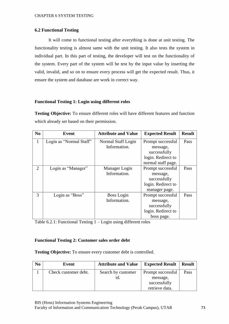
CHAPTER 6 SYSTEM TESTING
BIS (Hons) Information Systems Engineering
Faculty of Information and Communication Technology (Perak Campus), UTAR 73
6.2 Functional Testing
It will come to functional testing after everything is done at unit testing. The
functionality testing is almost same with the unit testing. It also tests the system in
individual part. In this part of testing, the developer will test on the functionality of
the system. Every part of the system will be test by the input value by inserting the
valid, invalid, and so on to ensure every process will get the expected result. Thus, it
ensure the system and database are work in correct way.
Functional Testing 1: Login using different roles
Testing Objective: To ensure different roles will have different features and function
which already set based on their permission.
No Event Attribute and Value Expected Result Result
1 Login as “Normal Staff” Normal Staff Login
Information.
Prompt successful
message,
successfully
login. Redirect to
normal staff page.
Pass
2 Login as “Manager” Manager Login
Information.
Prompt successful
message,
successfully
login. Redirect to
manager page.
Pass
3 Login as “Boss” Boss Login
Information.
Prompt successful
message,
successfully
login. Redirect to
boss page.
Pass
Table 6.2.1: Functional Testing 1 – Login using different roles
Functional Testing 2: Customer sales order debt
Testing Objective: To ensure every customer debt is controlled.
No Event Attribute and Value Expected Result Result
1 Check customer debt. Search by customer
id.
Prompt successful
message,
successfully
retrieve data.
Pass
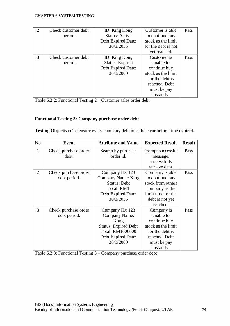
CHAPTER 6 SYSTEM TESTING
BIS (Hons) Information Systems Engineering
Faculty of Information and Communication Technology (Perak Campus), UTAR 74
2 Check customer debt
period.
ID: King Kong
Status: Active
Debt Expired Date:
30/3/2055
Customer is able
to continue buy
stock as the limit
for the debt is not
yet reached.
Pass
3 Check customer debt
period.
ID: King Kong
Status: Expired
Debt Expired Date:
30/3/2000
Customer is
unable to
continue buy
stock as the limit
for the debt is
reached. Debt
must be pay
instantly.
Pass
Table 6.2.2: Functional Testing 2 – Customer sales order debt
Functional Testing 3: Company purchase order debt
Testing Objective: To ensure every company debt must be clear before time expired.
No Event Attribute and Value Expected Result Result
1 Check purchase order
debt.
Search by purchase
order id.
Prompt successful
message,
successfully
retrieve data.
Pass
2 Check purchase order
debt period.
Company ID: 123
Company Name: King
Status: Debt
Total: RM1
Debt Expired Date:
30/3/2055
Company is able
to continue buy
stock from others
company as the
limit time for the
debt is not yet
reached.
Pass
3 Check purchase order
debt period.
Company ID: 123
Company Name:
Kong
Status: Expired Debt
Total: RM1000000
Debt Expired Date:
30/3/2000
Company is
unable to
continue buy
stock as the limit
for the debt is
reached. Debt
must be pay
instantly.
Pass
Table 6.2.3: Functional Testing 3 – Company purchase order debt
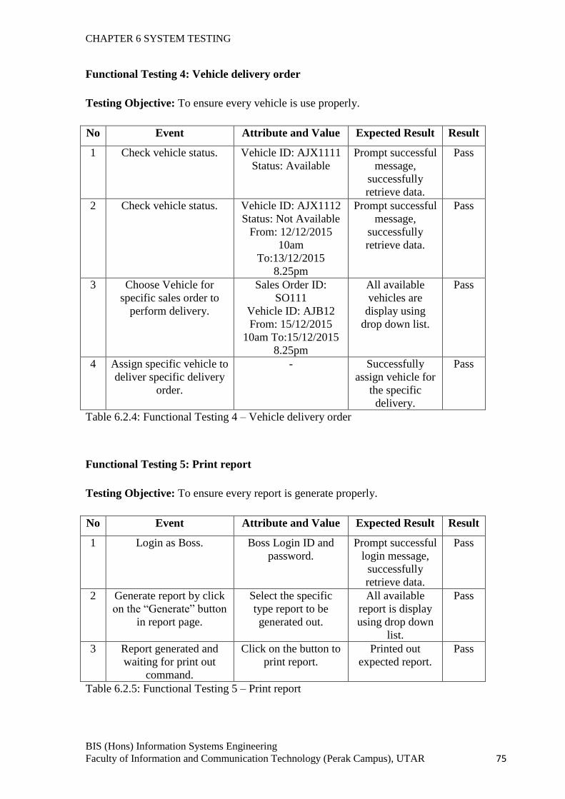
CHAPTER 6 SYSTEM TESTING
BIS (Hons) Information Systems Engineering
Faculty of Information and Communication Technology (Perak Campus), UTAR 75
Functional Testing 4: Vehicle delivery order
Testing Objective: To ensure every vehicle is use properly.
No Event Attribute and Value Expected Result Result
1 Check vehicle status. Vehicle ID: AJX1111
Status: Available
Prompt successful
message,
successfully
retrieve data.
Pass
2 Check vehicle status. Vehicle ID: AJX1112
Status: Not Available
From: 12/12/2015
10am
To:13/12/2015
8.25pm
Prompt successful
message,
successfully
retrieve data.
Pass
3 Choose Vehicle for
specific sales order to
perform delivery.
Sales Order ID:
SO111
Vehicle ID: AJB12
From: 15/12/2015
10am To:15/12/2015
8.25pm
All available
vehicles are
display using
drop down list.
Pass
4 Assign specific vehicle to
deliver specific delivery
order.
- Successfully
assign vehicle for
the specific
delivery.
Pass
Table 6.2.4: Functional Testing 4 – Vehicle delivery order
Functional Testing 5: Print report
Testing Objective: To ensure every report is generate properly.
No Event Attribute and Value Expected Result Result
1 Login as Boss. Boss Login ID and
password.
Prompt successful
login message,
successfully
retrieve data.
Pass
2 Generate report by click
on the “Generate” button
in report page.
Select the specific
type report to be
generated out.
All available
report is display
using drop down
list.
Pass
3 Report generated and
waiting for print out
command.
Click on the button to
print report.
Printed out
expected report.
Pass
Table 6.2.5: Functional Testing 5 – Print report
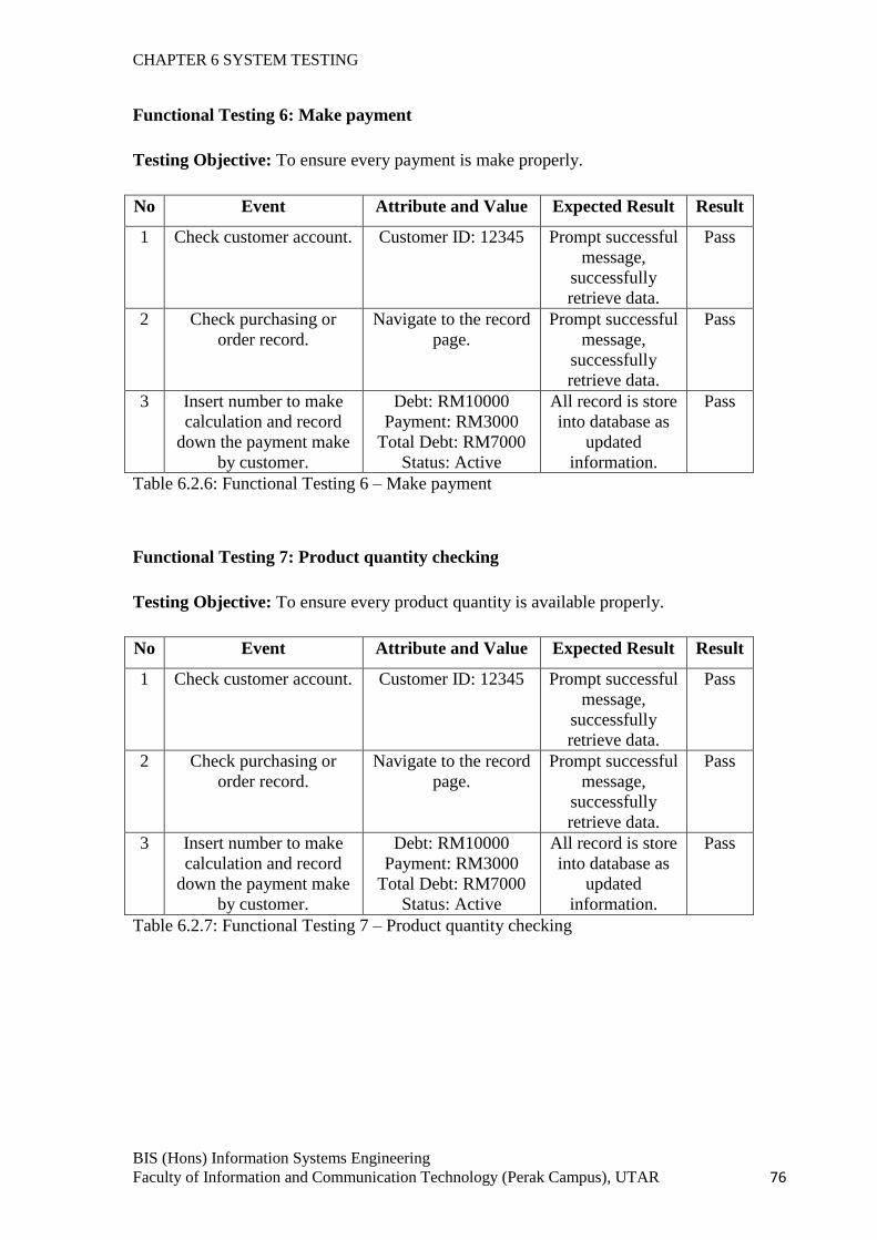
CHAPTER 6 SYSTEM TESTING
BIS (Hons) Information Systems Engineering
Faculty of Information and Communication Technology (Perak Campus), UTAR 76
Functional Testing 6: Make payment
Testing Objective: To ensure every payment is make properly.
No Event Attribute and Value Expected Result Result
1 Check customer account. Customer ID: 12345 Prompt successful
message,
successfully
retrieve data.
Pass
2 Check purchasing or
order record.
Navigate to the record
page.
Prompt successful
message,
successfully
retrieve data.
Pass
3 Insert number to make
calculation and record
down the payment make
by customer.
Debt: RM10000
Payment: RM3000
Total Debt: RM7000
Status: Active
All record is store
into database as
updated
information.
Pass
Table 6.2.6: Functional Testing 6 – Make payment
Functional Testing 7: Product quantity checking
Testing Objective: To ensure every product quantity is available properly.
No Event Attribute and Value Expected Result Result
1 Check customer account. Customer ID: 12345 Prompt successful
message,
successfully
retrieve data.
Pass
2 Check purchasing or
order record.
Navigate to the record
page.
Prompt successful
message,
successfully
retrieve data.
Pass
3 Insert number to make
calculation and record
down the payment make
by customer.
Debt: RM10000
Payment: RM3000
Total Debt: RM7000
Status: Active
All record is store
into database as
updated
information.
Pass
Table 6.2.7: Functional Testing 7 – Product quantity checking
CHAPTER 6 SYSTEM TESTING
BIS (Hons) Information Systems Engineering
Faculty of Information and Communication Technology (Perak Campus), UTAR 77
6.3 Integration Testing
It will come to integration testing after everything is done at unit testing and
functional testing. The integration testing is slightly different from the previous
testing. In this part of testing, the developer will test on the system which is already
integrated. Thus, it ensure the system and database are work in correct way. It is very
important since the system may work nicely at the previous testing, but after the
integration, it may occurs error in which all of the part will going to work together.
Because of this, this part may need several testers to find out the existing error.
Everything that had done in the previous testing will be repeated in this testing to
ensure everything work fine after a big integration work had done by the developer.
However, the errors might not be fully fixed and it still needs a final user to identify
the error incoming future. It is because the final user is the one who use the system
frequently and they will be the one who easy to recognized the errors. By letting the
final users to discover the errors, the developer can wait for the feedback. Once the
error is detected, then the developer will start to review the error and find a solution to
fix it. Anyway, the final user will only tested the final system in system testing which
means that the user will test the system while using it.
6.4 System Testing
System testing is the final testing which the tester will be the final user. The
system will be maintained if the final user has encountered an error while using the
system. Because of this, everything that related to the graphical user interface (GUI)
will not be able to make changes anymore. However, the technical error will be fixed
as soon as possible when the final user has encountered the error. The system will be
tested on different hardware to ensure it work fine at different machine. The system
testing is almost similar with the integration testing. Because of this, there is not much
need to do at this part for the developer. The differences between the integration
testing and system testing are the integration testing is tested by developer while the
system testing is tested by the final user. If there is no errors detected by the final user
while using the system for the long period, the job of developer is consider complete
and the system will be a complete final system.
CHAPTER 7 CONCLUSION
BIS (HONS) Information Systems Engineering 78
Faculty of Information and Communication Technology (Perak Campus), UTAR.
CHAPTER 7 CONCLUSION
In this era, the computerized inventory control management system has become a
common system that able to help the wholesalers to have a better management on their
business. Without the computerized inventory control management system, there will be a lot
of paper work is required to be done and longer time is needed to perform a simple task.
However, in Malaysia still have some wholesale company unwilling to change to use the
computerized inventory control management system and keep on using the old system. One
of the problems that may face for who are using the old system is about the difficulty in
finding the documents. The person who is finding the document may different to who is
storing that document. Even is the same person, he/she also may forget where the document
stored since there is a lot of files and other documentation are stored together.
Regardless, most of the traditional businessman having the mindset that the
computerized inventory control management system is difficult to use and it required certain
professional skill only able to handle the system since the graphic user interface of existing
system is complicated. In additional, they also deem that the differences between the old
system with the computerized is unlikely and transform from old system to new system will
needed a lot of money. Therefore, in order to solve the problems, the proposed inventory
control management system is developed with more user-friendly graphic interface that
enables the user easily familiar with it and providing the features that included in other
inventory control management system and with other extra feature. In short, the
proposed inventory control management system is able to help the wholesale company to
have better management as well as easier and more efficiency on data storing.
However, due to the limitation of times, the part for the mobile technologies is unable
to complete in this project. Although the desktop based application is finished on time, but
there is insufficient in complete the mobile based application. As a result, the time for doing
the FYP2 is not enough for the student to do the system in two different programming
languages. By the way, it will be no problems if the system is using a single programming
language to develop. Last but not least, it is good if there are the others student who try to do
the system in mobile based in the coming future.
REFERENCES
BIS (HONS) Information Systems Engineering 79
Faculty of Information and Communication Technology (Perak Campus), UTAR.
References
SDLC Software Prototype Model:[Online].Available at:
http://www.tutorialspoint.com/sdlc/sdlc_software_prototyping.htm Accessed on 1st
June 2014, 12.40pm.
SDLC, Software Development Life Cycle:[Online].Available at:
http://www.slideshare.net/swamy1431/sdlc-process-document Accessed on 30th
June
2014, 11.20am.
Incremental Prototyping:[Online].Available at: http://www.sqa.org.uk/e-
learning/IMAuthoring01CD/page_09.htm Accessed on 8th
June 2014, 10.20am.
AFIS (Automated Fingerprint ID System) & Passport Tracking. (2012). Retrieved
from Cen Metrix System Integrators: [Online]. Available at
http://www.cenmetrix.lk/afis-passport-tracking. Accessed on 1st July 2014, 11.20pm.
Anthony, I. I. (2007). Design and Implementation of an Automated Inventory Control
System For Nigerian Breweries.[Online]. Available at
http://pubs.caritasuni.edu.ng/download.php?file=projects/2011-
2012%20Projects/Computer%20Engineering/DESIGN_AND_IMPLEMENTATION_
OF_AN_AUTOMATED_INVENTORY_CONTROL_SYSTEM_FOR_NIGERIAN_
BREWERIES_PLC_ENUGU.pdf/. Accessed on 2nd
June 2014, 7.30pm.
Arina Ramlee, D. H. (2006, 4 4). Inventory Management System. Retrieved 4 2, 2014.
[Oline]. Available at
http://courses.cs.washington.edu/courses/cse403/06sp/lco/chhayb/LCO.doc. Accessed
on 29th
May 2014, 11.27am.
Moses, K. R. (2011). Automated Fingerprint Identification System. Retrieved from
National Criminal Justice Reference Service: [Online] Available at:
https://www.ncjrs.gov/pdffiles1/nij/225326.pdf. Accessed on 7th
June 2014, 9.33pm.
Wong, H. (2001). FileApproach.[Online] Available at
http://www.cs.cityu.edu.hk/~helena/cs34622000B/FileApproach.pdf. Accessed on 4th
June 2014, 10.03pm.
Creamer. N (2005) Inventory Technology. [Online] Available at
http://www.lbmjournal.com/article/36. Accessed on 27th
June 2014, 7.27pm.
REFERENCES
BIS (HONS) Information Systems Engineering 80
Faculty of Information and Communication Technology (Perak Campus), UTAR.
Sparrow. P (2011) Prototype Model: Advantages and Disadvantages. [Online]
Available at http://www.ianswer4u.com/2011/11/prototype-model-advantages-
and.html#axzz2ylZWmmtF. Accessed on 25th
June 2014, 8.20pm.
Bill C. H… (2007) Does RFID Reduce Out of Stocks? A Preliminary Analysis.
[Online] Available at http://rfid.uark.edu/papers/ITRI-WP058-1105.pdf.
Accessed on 6th
July 2014, 7.30pm.
Thomas. P (2012) Inventory Management System. [Online] Available at
http://dcag.com/images/INVENT01.pdf. Accessed on 29th
March 2015,
1.23pm.
Copyright (2010) Oracle Retail Store Inventory Management. [Online]
Available at http://www.oracle.com/us/products/applications/047105.pdf.
Accessed on 29th
March 2015, 2.45pm.
APPENDICES
BIS (HONS) Information Systems Engineering A - 1
Faculty of Information and Communication Technology (Perak Campus), UTAR.
APPENDICES
APPENDICES
FINAL YEAR PROJECT WEEKLY REPORT (Project I / Project II)
Trimester, Year: 1 , 3 Study week no.: 2
Student Name & ID: Ng Hock Li 1300545
Supervisor: Mr. Chee Chin Hoong
Project Title: Inventory Control System For Wholesale Business
1. WORK DONE Done review on the previous preliminary report and final year report 1. Start to state out the part that needs an improvement and plan a schedule.
2. WORK TO BE DONE Review previous final year project 1 and make improvement on the previous work. Start work on FYP2 Chapter 1: Introduction.
3. PROBLEMS ENCOUNTERED Found that the content in the final year project 1 report are not done well. Need to redo a lot of work to make improvement.
4. SELF EVALUATION OF THE PROGRESS Plan a schedule for myself to make sure everything is finish on time. Try best to reduce grammar error and use simple for easy read and understand. The work is finished on time as planned.
________________________ _________________________
Supervisor’s signature Student’s signature
APPENDICES
FINAL YEAR PROJECT WEEKLY REPORT (Project I / Project II)
Trimester, Year: 1, 3 Study week no.: 4
Student Name & ID: Ng Hock Li 1300545
Supervisor: Mr. Chee Chin Hoong
Project Title: Inventory Control System For Wholesale Business
1. WORK DONE Weekly meet with my supervisor, Mr. Chee Chin Hoong. We have conduct the discussion. The normal discussion regarding FYP1 during the meeting. Finished Chapter 1: Introduction.
2. WORK TO BE DONE Get full explanation and guidelines from supervisor and start to work on remaining part by following the guidelines. Start to do benchmarking on existing system.
3. PROBLEMS ENCOUNTERED Hard to make appointment with supervisor since the class schedule almost crashes with the supervisor free time. Internet connection weak at hometown and slow down the progress of work.
4. SELF EVALUATION OF THE PROGRESS Work very hard on study and research the existing system. Find out and mark down all the strength and weaknesses of current system to make sure it is useful for my system.
________________________ _________________________
Supervisor’s signature Student’s signature

APPENDICES
FINAL YEAR PROJECT WEEKLY REPORT (Project I / Project II)
Trimester, Year: 1, 3 Study week no.: 6
Student Name & ID: Ng Hock Li 1300545
Supervisor: Mr. Chee Chin Hoong
Project Title: Inventory Control System For Wholesale Business
1. WORK DONE Finished most of the document part. Interview is conducted to specific company. Read back others taken subject to revise how to draw the diagram.
2. WORK TO BE DONE Start to work on system design. Start to draw the relevant diagram. Complete Gantt Chart.
3. PROBLEMS ENCOUNTERED Submission date is near and there is a lot of thing need to be completed. Consume time on planning how the system works. Feel like not enough time to complete Android based program. Due to CNY holiday, a lot of things need to be done.
4. SELF EVALUATION OF THE PROGRESS Do research and learn very hard on the programming language. Searching study material for long time through the Google, Youtube, etc.
________________________ _________________________
Supervisor’s signature Student’s signature
APPENDICES
FINAL YEAR PROJECT WEEKLY REPORT (Project I / Project II)
Trimester, Year: 1, 3 Study week no.: 11
Student Name & ID: Ng Hock Li 1300545
Supervisor: Mr. Chee Chin Hoong
Project Title: Inventory Control System For Wholesale Business
1. WORK DONE Finished all of the documentation part. Prepared to meet Mr. Chee Chin Hoong for submission on next week.
2. WORK TO BE DONE Summarize whole project, do a conclusion. Arrange the the report. Sectioning the report according to FYP guideline. Submit project proposal for plagiarism checking. Print 2 set of project report. Submit to the supervisor with two set of project report with softcopy. Do the last weekly report.
3. PROBLEMS ENCOUNTERED No problem encountered in the documentation since the project had done. Time is limit for the coding parts.
4. SELF EVALUATION OF THE PROGRESS Put in a lot of effort for final checking the content of the project documentation report to make sure no big mistake.
________________________ _________________________
Supervisor’s signature Student’s signature
APPENDICES
FINAL YEAR PROJECT WEEKLY REPORT (Project I / Project II)
Trimester, Year: 1, 3 Study week no.: 12
Student Name & ID: Ng Hock Li 1300545
Supervisor: Mr. Chee Chin Hoong
Project Title: Inventory Control System For Wholesale Business
1. WORK DONE Finished 80% of the coding parts.
2. WORK TO BE DONE Almost complete the Java desktop based application.
3. PROBLEMS ENCOUNTERED Time is limit for the coding parts. Have to abandon the Android based since not much time left. Need to have better time management on next time.
4. SELF EVALUATION OF THE PROGRESS Put in a lot of effort for the coding parts. However, it is not enough time for one people to do the system with different programming language.
________________________ _________________________
Supervisor’s signature Student’s signature