Embed Size (px)
Citation preview
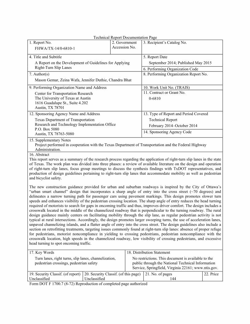
Technical Report Documentation Page
1. Report No.
FHWA/TX-14/0-6810-1
2. Government Accession No.
3. Recipient’s Catalog No.
4. Title and Subtitle
A Report on the Development of Guidelines for Applying Right-Turn Slip Lanes
5. Report Date
September 2014; Published May 2015
6. Performing Organization Code 7. Author(s)
Mason Gemar, Zeina Wafa, Jennifer Duthie, Chandra Bhat
8. Performing Organization Report No.
9. Performing Organization Name and Address
Center for Transportation Research The University of Texas at Austin 1616 Guadalupe St., Suite 4.202 Austin, TX 78701
10. Work Unit No. (TRAIS) 11. Contract or Grant No.
0-6810
12. Sponsoring Agency Name and Address
Texas Department of Transportation Research and Technology Implementation Office P.O. Box 5080 Austin, TX 78763-5080
13. Type of Report and Period Covered
Technical Report
February 2014–October 2014
14. Sponsoring Agency Code
15. Supplementary Notes Project performed in cooperation with the Texas Department of Transportation and the Federal Highway Administration.
16. Abstract This report serves as a summary of the research process regarding the application of right-turn slip lanes in the state of Texas. The work plan was divided into three phases: a review of available literature on the design and operation of right-turn slip lanes, focus group meetings to discuss the synthesis findings with TxDOT representatives, and production of design guidelines pertaining to right-turn slip lanes that accommodate mobility as well as pedestrian and bicyclist safety.
The new construction guidance provided for urban and suburban roadways is inspired by the City of Ottawa’s “urban smart channel” design that incorporates a sharp angle of entry into the cross street (~70 degrees) and delineates a narrow turning path for passenger cars using pavement markings. This design promotes slower turn speeds and enhances visibility of the pedestrian crossing location. The sharp angle of entry reduces the head turning required of motorists to search for gaps in oncoming traffic and thus, improves driver comfort. The design includes a crosswalk located in the middle of the channelized roadway that is perpendicular to the turning roadway. The rural design guidance mainly centers on facilitating mobility through the slip lane, as regular pedestrian activity is not typical at rural intersections. Accordingly, the design promotes larger sweeping turns, the use of acceleration lanes, unpaved channelizing islands, and a flatter angle of entry into the cross street. The design guidelines also include a section on retrofitting treatments, targeting issues commonly found at right-turn slip lanes: absence of proper refuge for pedestrians, motorist noncompliance in yielding to crossing pedestrians, pedestrian noncompliance with the crosswalk location, high speeds in the channelized roadway, low visibility of crossing pedestrians, and excessive head turning to spot oncoming traffic.
17. Key Words
Turn lanes, right turns, slip lanes, channelization, pedestrian crossings, pedestrian safety
18. Distribution Statement
No restrictions. This document is available to the public through the National Technical Information Service, Springfield, Virginia 22161; www.ntis.gov.
19. Security Classif. (of report) Unclassified
20. Security Classif. (of this page) Unclassified
21. No. of pages 144
22. Price
Form DOT F 1700.7 (8-72) Reproduction of completed page authorized

A Report on the Development of Guidelines for Applying Right-Turn Slip Lanes Mason Gemar Zeina Wafa Jennifer Duthie Chandra Bhat
CTR Technical Report: 0-6810-1 Report Date: September 2014; Revised November 2014 Project: 0-6810 Project Title: Guidelines for Applying Right-Turn Slip Lanes Sponsoring Agency: Texas Department of Transportation Performing Agency: Center for Transportation Research at The University of Texas at Austin Project performed in cooperation with the Texas Department of Transportation and the Federal Highway Administration.
Center for Transportation Research The University of Texas at Austin 1616 Guadalupe St, Suite 4.202 Austin, TX 78701 http://ctr.utexas.edu/
v
Disclaimers Author's Disclaimer: The contents of this report reflect the views of the authors, who
are responsible for the facts and the accuracy of the data presented herein. The contents do not necessarily reflect the official view or policies of the Federal Highway Administration or the Texas Department of Transportation (TxDOT). This report does not constitute a standard, specification, or regulation.
Patent Disclaimer: There was no invention or discovery conceived or first actually reduced to practice in the course of or under this contract, including any art, method, process, machine manufacture, design or composition of matter, or any new useful improvement thereof, or any variety of plant, which is or may be patentable under the patent laws of the United States of America or any foreign country.
Engineering Disclaimer NOT INTENDED FOR CONSTRUCTION, BIDDING, OR PERMIT PURPOSES.
Project Engineer: Jennifer Duthie
vi
Acknowledgments The authors wish to express their sincere appreciation to all who provided assistance, guidance, and input on this project. Support from TxDOT and their representatives, including RTI and the PMC group, were instrumental to completion of the report and design guidelines developed for the project. Specifically, the TxDOT project manager, Darrin Jensen, and other PMC representatives, Chris Hehr, Robert Guydosh, and Scott Cunningham, deserve to be acknowledged for their efforts. Important input obtained from focus group meetings with additional TxDOT personnel was also valuable to the project and the quality of the work product. Those TxDOT attendees include Pete Krause, Adrian Martinez, Sonia Mercado, Brent Hillebrenner, and Leonard Polk. Other TxDOT personnel who provided important feedback on the developed design guidelines include Rory Meza, Director of the Roadway Design Section – Design Division, Michael Chacon, Traffic Operations Division, and Teri Kaplan, State Bicycle and Pedestrian Coordinator. The efforts of TxDOT representatives and level of participation were critical to the project and are a testament to the devotion of the department to provide a valuable product. The authors would also like to acknowledge the efforts of their support staff who provided valuable assistance. They would like to sincerely thank Lisa Macias, for administrative support, and Maureen Kelly, for report editing.
vii
Executive Summary
This report serves as a summary of the research process regarding the application of right-turn slip lanes in the state of Texas. The work plan was divided into three phases: a review of available literature on the design and operation of right-turn slip lanes, focus group meetings to discuss the synthesis findings with TxDOT representatives, and production of design guidelines pertaining to right-turn slip lanes that accommodate mobility as well as pedestrian and bicyclist safety.
According to the Crash Records Information System (CRIS) records retrieved from the Texas Department of Transportation (TxDOT) for the years 2007 to 2012, there is a recent upward trend in total number of crashes, including pedestrian-related incidents. Specifically, the number of pedestrian-related crashes involving right-turning vehicles increased 14 percent from 2010 to 2012. The crash statistics imply that intersections present safety challenges for crossing pedestrians and must be designed to account for the presence of pedestrians and their needs. One intersection configuration that may be problematic for pedestrians is a right-turn slip lane as it presents a crossing location outside of the physical area of the intersection. This separation facilitates larger curb radii and consequently, higher turning speeds. Typically the crossing location along the turning roadway is essentially uncontrolled; therefore, it is important to produce guidelines for the proper design of right-turn slip lanes that take pedestrian safety into account.
Accordingly, this research project culminated in new design guidelines for the application of right-turn slip lanes in the state of Texas to accommodate motorists, pedestrians, and bicyclists. The different elements of right-turn slip lanes were evaluated based on the available literature on slip lane design and operation (Task 1), as well as the feedback received during focus group meetings held with TxDOT personnel as part of Task 2 of this research project. The guidelines reflect the findings from this process.
The new construction guidance for urban and suburban roadways—included in Appendix A of this report—is inspired by the City of Ottawa’s “urban smart channel” design that incorporates a sharp angle of entry into the cross street (~70 degrees) and delineates a narrow turning path for passenger cars using pavement markings. This design promotes slower turn speeds and enhances visibility of the pedestrian crossing location. The sharp angle of entry reduces the head turning required of motorists to search for gaps in oncoming traffic and thus, improves driver comfort. The design includes a crosswalk located in the middle of the channelized roadway that is perpendicular to the turning roadway.
According to orientation and mobility (O&M) specialists interviewed for the NCHRP 3-89 project (Potts et al., 2011), the crosswalk layout and location should be consistent for all intersections where they are implemented. The NCHRP 3-72 survey (2006) results indicated that most state and local highway agencies preferred placing the crosswalk perpendicularly at the center of the channelizing island separating the right-turn lane. This allows pedestrians to cross the right-turn lane upstream of the merge area and perpendicular to the flow of traffic, providing better visibility of approaching vehicles and shortening the crossing length for pedestrians.
The proposed design facilitates the turning maneuver of larger vehicles by allowing them to utilize the striped inner radius area. With regards to auxiliary lanes, the guidance on urban and
viii
suburban right-turn slip lane design supports the use of deceleration lanes to allow motorists to slow down before negotiating the turn and help pedestrians identify vehicles intending to enter the slip lane. The guidelines discourage the use of acceleration lanes as they generally promote higher speeds and render the slip lane difficult to cross for pedestrians. “Ladder” pattern crosswalk markings are recommended as the transverse lines delineate the crossing location and help pedestrians with visual impairments with wayfinding, while the longitudinal markings enhance the visibility of the crosswalk for motorists. A 5-ft wide bike lane is accommodated in the design using the appropriate pavement markings for an intersection approach.
The rural design guidance mainly centers on facilitating mobility through the slip lane, as regular pedestrian activity is not typical at rural intersections. Accordingly, the design promotes larger sweeping turns, the use of acceleration lanes, unpaved channelizing islands, and a flatter angle of entry into the cross street. In the event that pedestrian activity increases in the future, these intersections can be retrofitted to accommodate area development and travel behavior.
Through the proceedings at the focus group meetings, the issue of retrofitting existing right-turn slip lanes to improve their safety conditions and make them more accommodating to pedestrians and bicyclists was emphasized. Accordingly, the design guidelines include a section on retrofitting treatments, targeting issues commonly found at right-turn slip lanes: absence of proper refuge for pedestrians, motorist noncompliance in yielding to crossing pedestrians, pedestrian noncompliance with the crosswalk location, high speeds in the channelized roadway, low visibility of crossing pedestrians, and excessive head turning to spot oncoming traffic.
The emerging designs and retrofitting treatments are a product of an iterative process whereby TxDOT personnel provided regular feedback to the research team on the different design elements of the right-turn slip lane as well as typical TxDOT practices.
ix
Table of Contents
1. Introduction ........................................................................................................................... 1
1.1 Research Process .................................................................................................................. 2
1.2 Report Organization ............................................................................................................. 2
2. Literature Review .................................................................................................................. 3
2.1 Background Information for Right-Turn Slip Lanes ............................................................ 3
2.1.1 Types of Right-Turn Lanes ........................................................................................... 6
2.1.2 Warrants ........................................................................................................................ 7
2.2 Safety .................................................................................................................................... 8
2.2.1 Motorist Safety.............................................................................................................. 8
2.2.2 Pedestrian Safety ........................................................................................................... 9
2.2.2.1 Pedestrian Detection Methods ............................................................................. 10
2.2.2.2 General Crash Statistics ....................................................................................... 11
2.2.2.3 Texas Crash Statistics .......................................................................................... 11
2.2.3 Bicyclist Safety ........................................................................................................... 14
2.3 Geometric Design ............................................................................................................... 15
2.3.1 Angle of Entry into Cross Street ................................................................................. 15
2.3.2 Turning Radius and Turning Angle ............................................................................ 16
2.3.3 Designing for Pedestrians ........................................................................................... 17
2.3.3.1 General Recommendations .................................................................................. 17
2.3.3.2 Pedestrians with Disabilities ............................................................................... 18
2.3.4 Channelizing Island Design ........................................................................................ 20
2.3.5 Signage ........................................................................................................................ 22
2.3.6 Lighting and Markings ................................................................................................ 24
2.3.7 Crosswalks .................................................................................................................. 24
2.3.8 Lane Widths ................................................................................................................ 29
2.3.8.1 Geometric Design for Pedestrians ....................................................................... 30
2.3.8.2 Geometric Design for Bicyclists ......................................................................... 30
2.3.8.3 Lane Widths and Saturation Flow Rates ............................................................. 31
2.3.8.4 Lane Widths and Running Speeds ....................................................................... 31
2.3.8.5 Safety of Narrow Lane Widths ............................................................................ 31
2.3.9 Auxiliary Lanes ........................................................................................................... 33
2.3.9.1 Effect on Motorists .............................................................................................. 34
2.3.9.2 Effect on Pedestrians ........................................................................................... 35
x
2.3.9.3 Effect on Bicyclists ............................................................................................. 35
2.4 TxDOT Design Guidance ................................................................................................... 35
2.5 Controls and Delays ........................................................................................................... 38
2.5.1 Microsimulation Study Results ................................................................................... 38
2.6 European Regulations ......................................................................................................... 40
2.6.1 England ....................................................................................................................... 40
2.6.1.1 Pedestrian Facilities ............................................................................................. 40
2.6.1.2 Bicycle Facilities ................................................................................................. 41
2.6.1.3 Traffic Calming Strategies .................................................................................. 41
2.6.2 Netherlands ................................................................................................................. 41
2.6.2.1 Pedestrian Facilities ............................................................................................. 41
2.6.2.2 Bicycle Facilities ................................................................................................. 42
2.6.3 Germany ...................................................................................................................... 43
2.6.3.1 Pedestrian Facilities ............................................................................................. 43
2.6.3.2 Bicycle Facilities ................................................................................................. 43
2.6.4 Switzerland ................................................................................................................. 43
2.6.4.1 Pedestrian Facilities ............................................................................................. 43
2.6.4.2 Bicycle Facilities ................................................................................................. 44
2.7 Cost/Benefit Studies of Free Right-Turning Movements ................................................... 44
2.8 Examples of Channelized Right-Turn Lanes in Texas ....................................................... 44
3. Focus Groups ....................................................................................................................... 51
3.1 First Focus Group ............................................................................................................... 51
3.1.1 Focus Group Setup ...................................................................................................... 51
3.1.2 Focus Group Proceedings ........................................................................................... 52
3.1.2.1 Design Elements .................................................................................................. 52
3.1.2.2 Hypothetical Scenarios ........................................................................................ 59
3.1.2.3 Right-Turn Slip Lanes in Texas .......................................................................... 62
3.1.2.4 Preliminary Guidelines ........................................................................................ 65
3.1.3 General Focus Group Commentary and Conclusions .................................................. 70
3.1.3.1 Pole Placement .................................................................................................... 71
3.1.3.2 Drainage .............................................................................................................. 71
3.1.3.3 System Retrofits .................................................................................................. 71
3.2 Second Focus Group ........................................................................................................... 72
3.2.1 Focus Group Setup ....................................................................................................... 72
xi
3.2.2 Focus Group Proceedings ............................................................................................. 72
3.2.2.1 TRB Webinar ...................................................................................................... 73
3.2.2.2 Potential Retrofitting Solutions ........................................................................... 74
3.2.2.3 Right-Turn Slip Lane Design .............................................................................. 88
4. Design Guidelines ................................................................................................................ 95
4.1 Summary Guidelines .......................................................................................................... 95
5. Conclusion ............................................................................................................................ 97
5.1. Conclusions and Recommendations ................................................................................... 97
5.2. Future Research .................................................................................................................. 98
Appendix A ................................................................................................................................ 105
Section 1 — Purpose ................................................................................................................... 2
Section 2 — Introduction ............................................................................................................ 3
Section 3 — New Construction ................................................................................................... 4
Section 4 — Retrofitting Treatments ........................................................................................ 16
Section 5 — References ............................................................................................................ 21

xii
xiii
List of Figures
Figure 1: Improved Design of Channelized Right-Turn Lanes (Umbs, 2010) ............................... 5 Figure 2: Right-Turn Lane (Fitzpatrick & Schneider, 2005) .......................................................... 6 Figure 3: Shared Lane with Island (Fitzpatrick & Schneider, 2005) .............................................. 6 Figure 4: Right-Turn Lane with Island (Fitzpatrick & Schneider, 2005) ....................................... 7 Figure 5: Right-Turn Lane with Island and Dedicated Downstream Lane (Fitzpatrick &
Schneider, 2005) ....................................................................................................................... 7 Figure 6: Bicycle Facility Placement for Right-Turn Lanes (AASHTO, 2012) ........................... 14 Figure 7: Begin Right Turn Lane Yield to Bikes Sign (MUTCD, 2011) ..................................... 14 Figure 8: Dropping and Re-Introducing Bicycle Lanes Where Right Turns Are Present
(AASHTO, 2012) .................................................................................................................... 14 Figure 9: Small Island Design (AASHTO, 2011) ......................................................................... 21 Figure 10: Intermediate Island Design (AASHTO, 2011) ............................................................ 21 Figure 11: Large Island Design (AASHTO, 2011) ....................................................................... 22 Figure 12: Signage Placement at Right-Turn Slip Lanes (MUTCD, 2011) ................................. 23 Figure 13: No Merge Area W4-5P Sign (MUTCD, 2012) ........................................................... 23 Figure 14: Yield Ahead W3-2 Sign (MUTCD, 2012) .................................................................. 23 Figure 15: Yield R1-2 Sign (MUTCD, 2012) ............................................................................... 24 Figure 16: Marked Crosswalk Located Upstream and Parallel to Sidewalk (adapted from
NCHRP 3-72, 2006d).............................................................................................................. 24 Figure 17: Marked Crosswalk Located Upstream and Perpendicular to Sidewalk (adapted
from NCHRP 3-72, 2006d) ..................................................................................................... 25 Figure 18: Marked Crosswalk Located at the Center and Perpendicular to Sidewalk
(adapted from NCHRP 3-72, 2006d) ...................................................................................... 25 Figure 19: Marked Crosswalk Located Downstream and Parallel to Sidewalk (adapted
from NCHRP 3-72, 2006d) ..................................................................................................... 26 Figure 20: Marked Crosswalk Located Downstream and Perpendicular to Sidewalk
(adapted from NCHRP 3-72, 2006d) ...................................................................................... 26 Figure 21: No Marked Crosswalk (adapted from NCHRP 3-72, 2006d) ..................................... 27 Figure 22: Crosswalk Marking on Channelized Right-Turn Slip Lanes (Henson, 2009) ............ 29 Figure 23: Median Pedestrian Refuge Area Flush with Roadway (TxDOT, 2013) ..................... 37 Figure 24: Raised Median Pedestrian Refuge Area (TxDOT, 2013) ............................................ 37 Figure 25: Channelized Right-Turn Lane Configuration [typ.] per TxDOT Standard PED-
12A (TxDOT, 2002) ............................................................................................................... 38 Figure 26: Channelized Right-Turn Lane at MLK and Southbound Guadalupe (Google
Maps, 2014) ............................................................................................................................ 45 Figure 27: Channelized Right-Turn Lane at I-35 Frontage Road and 15th Street (Google
Maps, 2014) ............................................................................................................................ 45 Figure 28: Channelized Right-Turn Lane at Southbound Lamar and 45th Street (Google
Maps, 2014) ............................................................................................................................ 46
xiv
Figure 29: Channelized Right-Turn Lane at Northbound San Jacinto and Dean Keeton (Google Maps, 2014) .............................................................................................................. 46
Figure 30: Channelized Right-Turn Lane at Westbound Dean Keeton and San Jacinto (Google Maps, 2014) .............................................................................................................. 47
Figure 31: Channelized Right-Turn Lane at Northbound Lamar and 38th Street (Google Maps, 2014) ............................................................................................................................ 47
Figure 32: Right-Turn Slip Lane at MoPac Expressway and West 35th Street (Google Maps, 2014) ............................................................................................................................ 48
Figure 33: Right-Turn Slip Lane at RM 620 and Parmer Lane (Google Maps, 2014) ................. 48 Figure 34: Channelized Right-Turn Lane at Southbound Guadalupe and West 38th Street
(Google Maps, 2014) .............................................................................................................. 49 Figure 35: Angle of Entry into Cross Street Design (ITE, 2006) ................................................. 54 Figure 36: Crosswalk Configurations (Adapted from NCHRP 3-72, 2006d) .............................. 57 Figure 37: Upstream Crosswalk with Downstream Yield Control ............................................... 59 Figure 38: Center Crosswalk with Deceleration Lane .................................................................. 60 Figure 39: Downstream Crosswalk with Acceleration and Deceleration Lanes .......................... 60 Figure 40: Yield Control with Acceleration Lane and No Marked Crosswalk ............................ 61 Figure 41: Signal Control with Center Crosswalk and Deceleration Lane ................................... 61 Figure 42: William Cannon at US 290 Center Crosswalk with Yield Sign (Google Maps,
2014) ....................................................................................................................................... 61 Figure 43: IH 35 NBFR and Airport Blvd, Austin, TX (Google Maps, 2014) ............................. 63 Figure 44: IH 35 NBFR and MLK Dr, Austin, TX (Google Maps, 2014) ................................... 63 Figure 45: IH 10 EBFR and Bingle Rd, Houston, TX (Google Maps, 2014) .............................. 63 Figure 46: Lamar St and 7th St, Ft. Worth, TX (Google Maps, 2014) ......................................... 63 Figure 47: IH 35 SBFR and 15th St, Austin, TX (Google Maps, 2014) ...................................... 63 Figure 48: US 290 and SH 71, Austin, TX (Google Maps, 2014) ................................................ 63 Figure 49: US 79 NBFR and Lemmon Ave, Dallas, TX (Google Maps, 2014) ........................... 64 Figure 50: US 290 EBFR and Brodie Ln, Austin, TX (Google Maps, 2014) .............................. 64 Figure 51: MLK Dr and Lamar Blvd, Austin, TX (Google Maps, 2014)..................................... 64 Figure 52: US 59 and Weslayan St, Houston, TX (Google Maps, 2014) ..................................... 64 Figure 53: IH 35 NBFR and Whitlock Ln, Carollton, TX (Google Maps, 2014) ........................ 64 Figure 54: Airport Blvd and Manor Rd, Austin, TX (Google Maps, 2014) ................................. 64 Figure 55: SH 35 and Airport Blvd, Houston, TX (Google Maps, 2014) .................................... 65 Figure 56: SH 199 and SH 347, Ft. Worth, TX (Google Maps, 2014) ......................................... 65 Figure 57: Parmer Lane and MoPac Expressway Northbound Frontage Road (Google
Maps, 2014) ............................................................................................................................ 71 Figure 58: Retrofit Example at an Intersection in Wilmington, NC (Toole Design Group,
2009) ....................................................................................................................................... 74 Figure 59: Channelized Right-Turn Lane Designed for Pedestrians Compared to a
Conventional Design (City of Ottawa, 2009) ......................................................................... 75
xv
Figure 60: Extension of Island Using Striping as per the Florida Department of Transportation Right-Turn Slip Lane Design (FDOT, 2014) ................................................. 76
Figure 61: Motorist Visibility of Crosswalk (Umbs, 2010) .......................................................... 79 Figure 62: Sign R1-5 “Yield Here to Pedestrians” (TxDOT, 2012b) ........................................... 80 Figure 63: RM 2222 and Burnet Road (Google Maps, 2014) ...................................................... 80 Figure 64: W10-15 Sign (Top Left), W16-9P sign (Bottom Left), W11-2 sign (Top
Right), W16-7P sign (Bottom Right) (TxDOT, 2012b) ......................................................... 81 Figure 65: R1-6 and R1-6a Warning Signs (TxDOT, 2012b) ...................................................... 81 Figure 66: Raised Crosswalk at RT Slip Lane (Road Crossings Green 2001) ............................. 83 Figure 67: Sound Strip Implementation in Charlotte, NC (Schroeder et al., 2010) ..................... 85 Figure 68: Slip Lane Removal Proposal on Bradhurst Plaza (Miller, 2014) ................................ 88 Figure 69: Right-Turn Slip Lane Design (Maryland State Highway Administration, n.d.) ......... 89 Figure 70: Example of a Slip Lane Design (Toole Design Group, 2009) .................................... 89 Figure 71: Detailed Pedestrian-Friendly Channelized Right-Turn Lane Using Urban
Smart Channel Design (City of Ottawa, 2009) ....................................................................... 90 Figure 72: Urban Smart Channel on Strandherd Drive, Ottawa (Google Maps, 2014) ................ 91 Figure 73: Island Design for the Urban Smart Channel Design (Google Maps, 2014) ................ 91 Figure 74: Urban Smart Channel Conceptual Design (City of Ottawa, 2009) ............................. 92 Figure 75: Channelized Right-Turn Design (Umbs, 2010) .......................................................... 93 Figure 76: Florida DOT Standard “17346 - Special Marking Areas” (FDOT, 2014) .................. 94 Figure 77: TxDOT Standard "Ped-12A - Pedestrian Facilities, Curb Ramps” (TxDOT,
2012a) ..................................................................................................................................... 94

xvi
xvii
List of Tables
Table 1: Benefits and Liabilities of Channelized Right-Turn Lanes (Chandler et al., 2013) ......... 4 Table 2: Texas Crash Statistics Years 2007 through 2012 (TxDOT, 2007–2012) ....................... 13 Table 3: Turning Angle, Radii, Lane Widths, and Island Sizes (AASHTO, 2011) ...................... 17 Table 4: Speeds and Stopping Sight Distances (AASHTO, 2011) ............................................... 18 Table 5: FHWA Warrants for Using Different Types of Bicycle Facilities (King, 2002) ........... 30 Table 6: Dutch Warrants for Using Different Types of Bicycle Facilities (King, 2002) ............. 31 Table 7: Deceleration Lengths for Right Turn Deceleration Lanes (Potts et al., 2011) ............... 33 Table 8: Storage Lengths for Right-Turn Lanes at Stop Controlled Intersections (Potts et
al., 2011) ................................................................................................................................. 33 Table 9: Volume Warrants for Using Deceleration Lanes for Urban Two-Lane Roadways
(McCoy et al., 1994) ............................................................................................................... 34 Table 10: Volume Warrants for Deceleration Lanes for Urban Four-Lane Roadways
(McCoy et al., 1994) ............................................................................................................... 34 Table 11: First Focus Group Attendees ........................................................................................ 52 Table 12: Geometric Design for Right-Turn Slip Lanes for Different Vehicle Mixes
(Table 9-18 in AASHTO Green Book [AASHTO, 2011]) ..................................................... 53 Table 13: Warrants for Auxiliary Lanes (TxDOT, 2011) ............................................................. 68 Table 14: Warrants for Auxiliary Lanes by State (TxDOT, 2011) ............................................... 68 Table 15: Second Focus Group Attendees .....................................................................................72

xviii
1
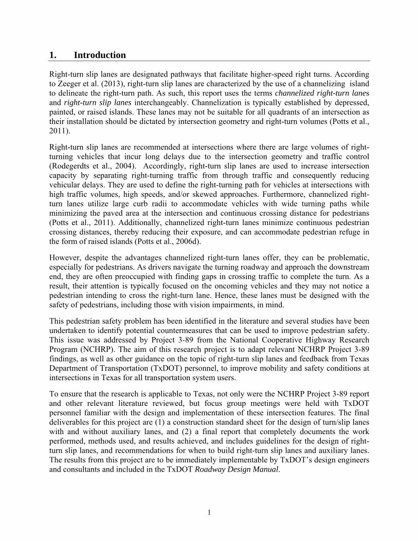
1. Introduction
Right-turn slip lanes are designated pathways that facilitate higher-speed right turns. According to Zeeger et al. (2013), right-turn slip lanes are characterized by the use of a channelizing island to delineate the right-turn path. As such, this report uses the terms channelized right-turn lanes and right-turn slip lanes interchangeably. Channelization is typically established by depressed, painted, or raised islands. These lanes may not be suitable for all quadrants of an intersection as their installation should be dictated by intersection geometry and right-turn volumes (Potts et al., 2011).
Right-turn slip lanes are recommended at intersections where there are large volumes of right-turning vehicles that incur long delays due to the intersection geometry and traffic control (Rodegerdts et al., 2004). Accordingly, right-turn slip lanes are used to increase intersection capacity by separating right-turning traffic from through traffic and consequently reducing vehicular delays. They are used to define the right-turning path for vehicles at intersections with high traffic volumes, high speeds, and/or skewed approaches. Furthermore, channelized right-turn lanes utilize large curb radii to accommodate vehicles with wide turning paths while minimizing the paved area at the intersection and continuous crossing distance for pedestrians (Potts et al., 2011). Additionally, channelized right-turn lanes minimize continuous pedestrian crossing distances, thereby reducing their exposure, and can accommodate pedestrian refuge in the form of raised islands (Potts et al., 2006d).
However, despite the advantages channelized right-turn lanes offer, they can be problematic, especially for pedestrians. As drivers navigate the turning roadway and approach the downstream end, they are often preoccupied with finding gaps in crossing traffic to complete the turn. As a result, their attention is typically focused on the oncoming vehicles and they may not notice a pedestrian intending to cross the right-turn lane. Hence, these lanes must be designed with the safety of pedestrians, including those with vision impairments, in mind.
This pedestrian safety problem has been identified in the literature and several studies have been undertaken to identify potential countermeasures that can be used to improve pedestrian safety. This issue was addressed by Project 3-89 from the National Cooperative Highway Research Program (NCHRP). The aim of this research project is to adapt relevant NCHRP Project 3-89 findings, as well as other guidance on the topic of right-turn slip lanes and feedback from Texas Department of Transportation (TxDOT) personnel, to improve mobility and safety conditions at intersections in Texas for all transportation system users.
To ensure that the research is applicable to Texas, not only were the NCHRP Project 3-89 report and other relevant literature reviewed, but focus group meetings were held with TxDOT personnel familiar with the design and implementation of these intersection features. The final deliverables for this project are (1) a construction standard sheet for the design of turn/slip lanes with and without auxiliary lanes, and (2) a final report that completely documents the work performed, methods used, and results achieved, and includes guidelines for the design of right-turn slip lanes, and recommendations for when to build right-turn slip lanes and auxiliary lanes. The results from this project are to be immediately implementable by TxDOT’s design engineers and consultants and included in the TxDOT Roadway Design Manual.
2
1.1 Research Process The research effort was divided into three phases: literature review, focus group meetings, and development of design guidelines. The first task entailed a review of prior research and available guidance on the design and implementation of right-turn slip lanes, including pedestrian crossing treatments, as well as potential safety-related issues associated with them.. This task inspired the development of hypothetical scenarios and design strategies which were discussed with a team of TxDOT representatives in a focus group meeting held at the Center for Transportation Research at The University of Texas at Austin.
The feedback received during the meeting led to a refinement of the individual design elements reviewed, in addition to stimulating further research about retrofitting treatments for right-turn slip lanes. Accordingly, the research team drafted material on potential treatments at existing right-turn slip lanes designed to improve safety. After compiling applicable information, the team held a second focus group in which retrofitting treatments for existing right-turn slip lanes were discussed and feedback received. Feedback was obtained on retrofitting treatments and strategies, as well as the preferred layout for new construction projects. The third task required the juxtaposition of the information gathered from the first task and the feedback from the focus groups to develop design guidance for the construction of right-turn slip lanes, along with recommendations for the treatment of existing intersections with problematic right-turn slip lanes. The first draft of the design guidelines was submitted at the end of July, and was then refined based on feedback from TxDOT representatives.
1.2 Report Organization The following report is organized as follows: Section 2 contains the literature review findings; Section 3 relates the feedback received from the focus groups; Section 4 presents the research team’s guidance on constructing new right-turn slip lanes as well as retrofitting existing ones; and Section 5 summarizes the research project and outlines areas of potential future research. Appendix A provides the design guidelines and construction standard drawings for slip lane design, meant to be added to the TxDOT Roadway Design Manual as “Appendix D — Right-Turn Slip Lane Design Guidelines.”
3
2. Literature Review
The project’s first task was to review the available guidance on the design of right-turn slip lanes as well as their key problems. The NCHRP Project 3-72 and NCHRP Project 3-89 reports were the most important reports reviewed since a primary goal of this project was to adapt their guidance for Texas. This review was followed by the focus group meetings with TxDOT representatives (as detailed in Section 3). The literature review provided the research team with supporting material for developing design guidelines and recommendations for channelized right-turn lanes. It helped identify key problems in channelized right-turn lanes as well as design ranges for right-turn slip lane design elements.
2.1 Background Information for Right-Turn Slip Lanes The AASHTO A Policy on Geometric Design of Highways and Streets (2011), known as the Green Book, defines channelization as the separation of traffic movements using islands or pavement markings. Transportation planners often consider installing a right-turn slip lane because of the following benefits:
• reduces the number of crossing vehicle paths.
• allows for the control of the angles at which vehicles merge, diverge, or cross.
• decreases the pavement width through the turn and, as a result, decreases the probability that a vehicle deviates from its designated path.
• prioritizes movements.
• provides refuge for pedestrians.
• allows vehicles to store and queue separate from through-traffic lanes.
• allows for the provision of traffic control devices within the island to make them more perceptible.
• controls prohibited turns.
• controls vehicle speeds.
Chandler et al. (2013) summarize the potential benefits and liabilities of right-turn slip lanes (see Table 1).
4
Table 1: Benefits and Liabilities of Channelized Right-Turn Lanes (Chandler et al., 2013) Characteristics Potential Benefits Potential Liabilities Safety Separation of decelerating
right-turn vehicles • Potential for sideswipe and
rear-end collisions on departure leg
• Pedestrian crosswalk design compatibility
Operations • Higher right-turn capacity
• Shorter green time
• Less delay for following through vehicles
None identified. “Australian Right” may not accommodate large vehicles.
Multimodal Pedestrian refuge area • Longer pedestrian crossing distance and exposure
• Higher vehicle speeds
Physical Smaller impact than a lane along the right-of-way
Larger intersection footprint
Socioeconomic Support a mixed use, walkable community (by reducing pedestrian crossing distances and providing refuge)
• Right-of-way costs
• Access restrictions to property
Enforcement, Education, and Maintenance
None identified Higher maintenance of islands, marking, signing
The AASHTO Green Book (2011) recommends consideration of the following design principles when designing channelized roadways:
• Motorists should not be expected to make multiple decisions.
• Paths that require large turns (>900) or that require sudden and sharp reverse curves should be avoided.
• Where pedestrians or driveways are present at the intersection, it is recommended that the turning roadways be controlled with a yield, stop, or signal control and that the angle of intersection be greater than 60 degrees.
• The angle of intersection between merging traffic should be such that it allows for suitable sight distance.
• Refuge islands should not interfere with bicycle lanes.
• Channelizing islands should control for prohibited maneuvers.
The ITE report on designing major urban thoroughfares for walkable communities (ITE, 2006) recommends the following considerations when designing right-turn slip lanes:
5
• Use when signalized intersections have high right-turning traffic volumes and low pedestrian volumes. Also, use to accommodate for large turning vehicles.
• If pedestrian volumes are high, install a pedestrian signal for crossing the right-turn lane.
• Provide a low-angle right turn (~1120) to maintain low speeds through the turn and thereby reduce conflicts with pedestrians.
• Provide accessible islands in terms of size and features. Painted islands are not satisfactory.
• Maintain a 12-foot wide right-turn lane unless the lane is designed for large vehicles (in which case lane widths can be 16 feet or wider). The width of the lane controls turning speed.
• Design speeds for urban channelized right-turn lanes should be in the range of 5 to 10 miles per hour and should allow for good pedestrian visibility.
• Consider providing signage to remind drivers of their legal obligation to yield to pedestrians. Signs should be placed in advance of or at the crossing location.
• Signalize the pedestrian crossing when:
o There are multiple turning lanes.
o Crossing is unsafe due to poor visibility, large volumes, or high speed turning traffic.
o There is high pedestrian-vehicle crash.
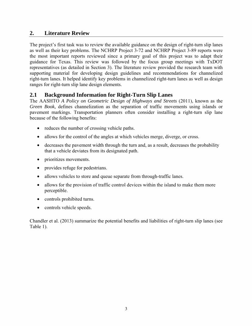
In the past, right-turn lanes accommodated high turning speeds, resulted in low visibility of pedestrians, and thus did not provide for safe pedestrian crossings. An improved method for designing right-turn lanes adopts slow speeds and a 55–70 degree angle between merging vehicle flows (as shown in Figure 1). This allows for good visibility of pedestrians (Umbs, 2010).
Figure 1: Improved Design of Channelized Right-Turn Lanes (Umbs, 2010)
6
In general, the Federal Highway Administration (FHWA) (Umbs, 2010) recommends the following design guidelines for right-turn slip lanes:
• Long radius (150–275 feet) followed by short radius (25–40 feet) depending on design vehicle
• Crosswalk is one car length back from the cross street
• Length to width ratio of the channelizing island should be two to one
• Cut through medians and islands for pedestrians
2.1.1 Types of Right-Turn Lanes Fitzpatrick and Schneider (2005) identify four types of right-turn lanes:
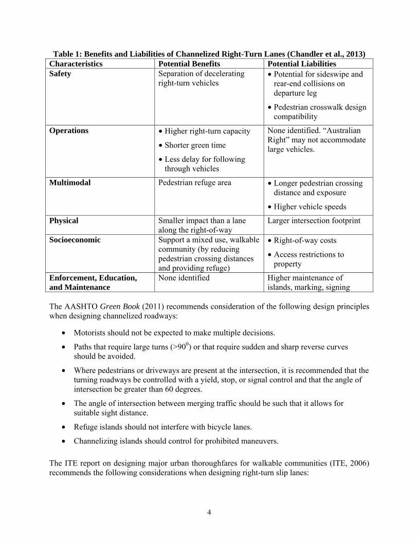
1. Non-Shared Right-turn lane:
This configuration (shown in Figure 2) allows for right-turning movements at the red light, which reduces right-turn queues and their impact on through traffic and intersection capacity. Also, drivers of right-turning vehicles have to reduce their speed and look for oncoming traffic, which leads to improved levels of safety for pedestrians.
However, such configurations may require that all vehicles stop at the signal, which increases delays and queues for the right-turning movement. Also, there is no channelizing island in this configuration where control devices can be placed. Finally, the absence of the island means there is no refuge for pedestrians.
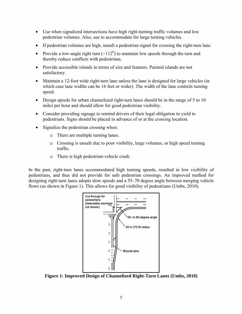
2. Shared lane with island:
The presence of the island in this configuration (shown in Figure 3) allows for provision of traffic control devices and serves as pedestrian refuge. Moreover, the turning vehicles are, more or less, removed from the through queue.
However, this configuration may lead to higher turning speeds. Also, as the lane is shared, through-vehicle queues may block the entry into the right-turn lane and decrease the intersection capacity.
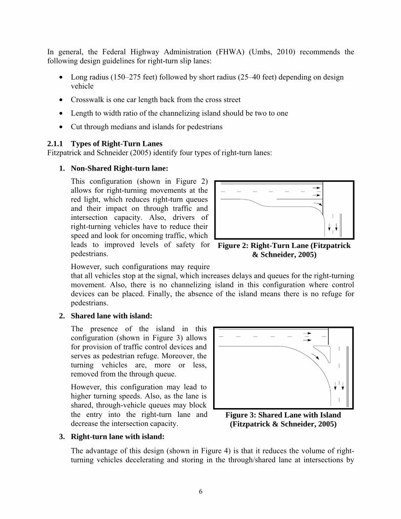
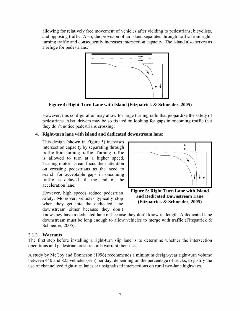
3. Right-turn lane with island:
The advantage of this design (shown in Figure 4) is that it reduces the volume of right-turning vehicles decelerating and storing in the through/shared lane at intersections by
Figure 2: Right-Turn Lane (Fitzpatrick & Schneider, 2005)
Figure 3: Shared Lane with Island (Fitzpatrick & Schneider, 2005)
7
allowing for relatively free movement of vehicles after yielding to pedestrians, bicyclists, and opposing traffic. Also, the provision of an island separates through traffic from right-turning traffic and consequently increases intersection capacity. The island also serves as a refuge for pedestrians.
Figure 4: Right-Turn Lane with Island (Fitzpatrick & Schneider, 2005)
However, this configuration may allow for large turning radii that jeopardize the safety of pedestrians. Also, drivers may be so fixated on looking for gaps in oncoming traffic that they don’t notice pedestrians crossing.
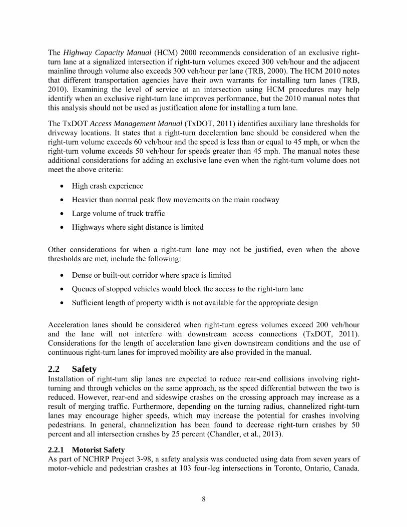
4. Right-turn lane with island and dedicated downstream lane:
This design (shown in Figure 5) increases intersection capacity by separating through traffic from turning traffic. Turning traffic is allowed to turn at a higher speed. Turning motorists can focus their attention on crossing pedestrians as the need to search for acceptable gaps in oncoming traffic is delayed till the end of the acceleration lane.
However, high speeds reduce pedestrian safety. Moreover, vehicles typically stop when they get into the dedicated lane downstream either because they don’t know they have a dedicated lane or because they don’t know its length. A dedicated lane downstream must be long enough to allow vehicles to merge with traffic (Fitzpatrick & Schneider, 2005).
2.1.2 Warrants The first step before installing a right-turn slip lane is to determine whether the intersection operations and pedestrian crash records warrant their use.
A study by McCoy and Bonneson (1996) recommends a minimum design-year right-turn volume between 440 and 825 vehicles (veh) per day, depending on the percentage of trucks, to justify the use of channelized right-turn lanes at unsignalized intersections on rural two-lane highways.
Figure 5: Right-Turn Lane with Island and Dedicated Downstream Lane (Fitzpatrick & Schneider, 2005)
8
The Highway Capacity Manual (HCM) 2000 recommends consideration of an exclusive right-turn lane at a signalized intersection if right-turn volumes exceed 300 veh/hour and the adjacent mainline through volume also exceeds 300 veh/hour per lane (TRB, 2000). The HCM 2010 notes that different transportation agencies have their own warrants for installing turn lanes (TRB, 2010). Examining the level of service at an intersection using HCM procedures may help identify when an exclusive right-turn lane improves performance, but the 2010 manual notes that this analysis should not be used as justification alone for installing a turn lane.
The TxDOT Access Management Manual (TxDOT, 2011) identifies auxiliary lane thresholds for driveway locations. It states that a right-turn deceleration lane should be considered when the right-turn volume exceeds 60 veh/hour and the speed is less than or equal to 45 mph, or when the right-turn volume exceeds 50 veh/hour for speeds greater than 45 mph. The manual notes these additional considerations for adding an exclusive lane even when the right-turn volume does not meet the above criteria:
• High crash experience
• Heavier than normal peak flow movements on the main roadway
• Large volume of truck traffic
• Highways where sight distance is limited
Other considerations for when a right-turn lane may not be justified, even when the above thresholds are met, include the following:
• Dense or built-out corridor where space is limited
• Queues of stopped vehicles would block the access to the right-turn lane
• Sufficient length of property width is not available for the appropriate design
Acceleration lanes should be considered when right-turn egress volumes exceed 200 veh/hour and the lane will not interfere with downstream access connections (TxDOT, 2011). Considerations for the length of acceleration lane given downstream conditions and the use of continuous right-turn lanes for improved mobility are also provided in the manual.
2.2 Safety Installation of right-turn slip lanes are expected to reduce rear-end collisions involving right-turning and through vehicles on the same approach, as the speed differential between the two is reduced. However, rear-end and sideswipe crashes on the crossing approach may increase as a result of merging traffic. Furthermore, depending on the turning radius, channelized right-turn lanes may encourage higher speeds, which may increase the potential for crashes involving pedestrians. In general, channelization has been found to decrease right-turn crashes by 50 percent and all intersection crashes by 25 percent (Chandler, et al., 2013).
2.2.1 Motorist Safety As part of NCHRP Project 3-98, a safety analysis was conducted using data from seven years of motor-vehicle and pedestrian crashes at 103 four-leg intersections in Toronto, Ontario, Canada.
9
The safety of intersection approaches with right-turn slip lanes, conventional right-turn lanes, and shared through/right-turn lanes were compared.
Crash predictions at the departure end of the right-turn, or where the turning vehicle merges onto the cross street, were found to be higher for conventional right-turn lanes than for channelized right-turn lanes and shared through/right-turn lanes. Shared through/right-turn lanes had the lowest merge crash predictions, whereas conventional right-turn lanes had the highest estimated crash rates. For rear-end and sideswipe crashes, the type of right-turn approach did not appear to impact the estimated number of crashes. The annual crash predictions for channelized right-turn lanes and shared through/right-turn lanes were found to be similar, and 70–80 percent lower than those for conventional right-turn lanes. This can be attributed to the fact that conventional right-turn lanes generally have longer pedestrian crossing distances.
Another study by Dixon et al. (1999) observed the crash history at 17 signalized intersections with various right-turn treatments:
• Shared right-turn lane, no island, merge, and no additional control
• Exclusive right-turn lane, no island, merge, and no additional control
• Exclusive right-turn lane, raised island, acceleration lane, and no additional control
• Exclusive right-turn lane, raised island, merge, and yield control
• Shared right-turn lane, raised island, large turning radius, merge, and yield control
The authors extracted the following findings:
• Channelized islands were found to reduce the number of right-angle crashes.
• Sideswipe crashes increase when the right-turning movement is given an exclusive lane.
• The provision of an acceleration lane, without additional control, does not reduce the number of rear-end crashes.
Another study by Tarawneh and McCoy (1996) studied four intersections, three of which had a channelized right-turn lane. They concluded that drivers typically drive 4 to 5 mph faster on channelized right-turn lanes than they do on approaches where channelized right-turn lanes are not provided. Moreover, drivers on channelized right-turn lanes tend to negotiate the right turn without coming to a full stop. However, the authors could not draw conclusions about safety from this study.
Another study by McCoy et al. (1995) did not find safety benefits— or drawbacks—for channelized right-turn lanes.
2.2.2 Pedestrian Safety A five-state study that looked at more than 5,000 vehicle-pedestrian collisions found that 38 percent of all crashes occurred at intersections, with 30 percent of these crashes occurring due to a turning movement.
10
The geometry of the channelized right-turn lane has an impact on the speed at which vehicles can make the turn successfully. A study by Zeeger et al. (2002) determined that the speed of the vehicle and the severity of the vehicle-pedestrian collision are directly correlated. In fact, there is a 5-percent chance that a pedestrian is killed when struck by a vehicle travelling 20 mph. This chance increases to 45 percent if the vehicle is travelling at 30 mph. The chance of fatality reaches 85 percent if the vehicle is travelling at 40 mph. This is because, as speed increases, the probability of spotting a pedestrian and slowing down in time decreases.
2.2.2.1 Pedestrian Detection Methods
As mentioned earlier, in the presence of pedestrians, yield, stop, or signal controls can be used to reduce conflict with motorists. To optimize the traffic operations of the right-turn slip lane, a signal can be actuated, calling the walk signal only in the presence of pedestrians. A report published by the FHWA (2001) evaluated automated pedestrian detection methods at signalized intersections. The following methods were discussed as part of the evaluation efforts.
I. For actuated signals, the pedestrian signal may not provide a walk indication unless pedestrians push the designated button that alerts the system that a pedestrian is present. However, a study done by Zeeger et al. (1985) found that almost 50 percent of pedestrians observed did not use a push button in order to cross because they either didn’t know the button existed or (as many signals incorporate the pedestrian phasing into their cycles) the time gap between when the pedestrian pushes the button and provision of a walk indication is such that the pedestrian concludes that the button is not functional. Pedestrians with vision impairment or physical disabilities may not be aware of the button or may not be able to locate it to activate the signal.
II. Microwave detectors function by generating energy waves at a particular frequency. A pedestrian is detected when these waves reflect off of them and the frequency of the reflected wave is different than that of the emitted one.
III. Infrared presence detection is commonly used in grocery stores, shops, banks, etc. It is not effective, however, if the object remains stationary. Also, this kind of technology cannot be used to identify a pedestrian’s direction of travel or how many pedestrians are present.
Both II and III detect pedestrians as soon as they walk into the “detection zone.” To avoid stopping traffic for pedestrians who happen to cross the detection zone but do not intend to cross the street, the system can be programmed such that the pedestrian must remain in the detection soon for a minimum specified time before the walk signal is called (Hughes et al., 2001).
The United Kingdom uses Puffin (Pedestrian User-Friendly Intelligent) crossings that respond to pedestrian presence and do not force drivers to stop unnecessarily when pedestrians are absent. The presence of pedestrians is detected using a pressure mat or an infrared detector. Pressure mats identify when a pedestrian first enters the detection zone, as well as track the pedestrian so that the call for a pedestrian signal can be cancelled if the pedestrian leaves the detection zone prior to the appearance of the walk signal. An additional sensor can be installed to detect the presence of pedestrians in the crosswalk in order to extend the green time of the signal to accommodate pedestrians who require more time to cross (Hughes et al., 2001).
11
Automated pedestrian signals were installed in Los Angeles, California (microwave and infrared + crosswalk sensors), Phoenix, Arizona (microwave), and Rochester, New York (microwave). The intersections were videotaped to compare motorist and pedestrian behavior before and after the treatment. The results show that pedestrian detection methods increase the compliance of pedestrians at signals, i.e., “a decrease in the likelihood that pedestrians will begin crossing during the steady (don’t walk) signal, which decreases the likelihood of encountering opposing traffic” (Hughes et al., 2001).
Automatic pedestrian detectors have proven to be effective not because of the nature of the messages they convey to the pedestrians (as these are not different than those initiated by the conventional push button) but because they ensure that a pedestrian will receive a WALK signal and will at least have a minimum period to cross. Also, it was empirically found that the installation of automatic detectors reduced conflicts between pedestrians and motorists. Particularly, conflicts between pedestrians and right-turning vehicles were found to be reduced by 40 percent (Hughes et al., 2001).
2.2.2.2 General Crash Statistics
According to the National Pedestrian Crash Report published by the National Highway Traffic Safety Administration in 2008, the states with the highest pedestrian fatality rates were California, Florida, and Texas. The five cities with highest fatality rates were found to be New York, Los Angeles, Chicago, Phoenix, and Houston.
Most pedestrian fatalities were found to occur on urban roadways or at non-intersection locations. The highest percentage of pedestrian fatalities was found to occur between the hours of 6:00 and 9:00 p.m. More than two-thirds of the involved pedestrians were male, though males comprise less than half the U.S. population. While representing roughly 80 percent of the U.S. population, only 60 percent of pedestrians killed in crashes were white. Conversely, 20 percent of the pedestrians killed were of Hispanic origin. Twenty-one percent of pedestrian fatalities were people 65 years old and older, although people in that age group make up just 13 percent of the U.S. population (Chang, 2008).
It is noteworthy that most pedestrian fatalities occurred when the motorist was obeying the speed limit. The highest pedestrian fatality rate per pedestrian crash was observed on roadways with posted speed limits above 45 mph. According to Fitzpatrick & Schneider (2005), 80 percent of pedestrians are killed when struck by motor vehicles traveling 35–45 mph; only 5 percent are killed at speeds of 18 mph. This has implications on the design speed or posted speed limit as well as other factors presumed to affect pedestrian safety.
The probability of a pedestrian crash resulting in a fatality increases with worsening light conditions and the probability of a pedestrian fatality increases with worsening weather conditions at time of crash (Chang, 2008).
2.2.2.3 Texas Crash Statistics
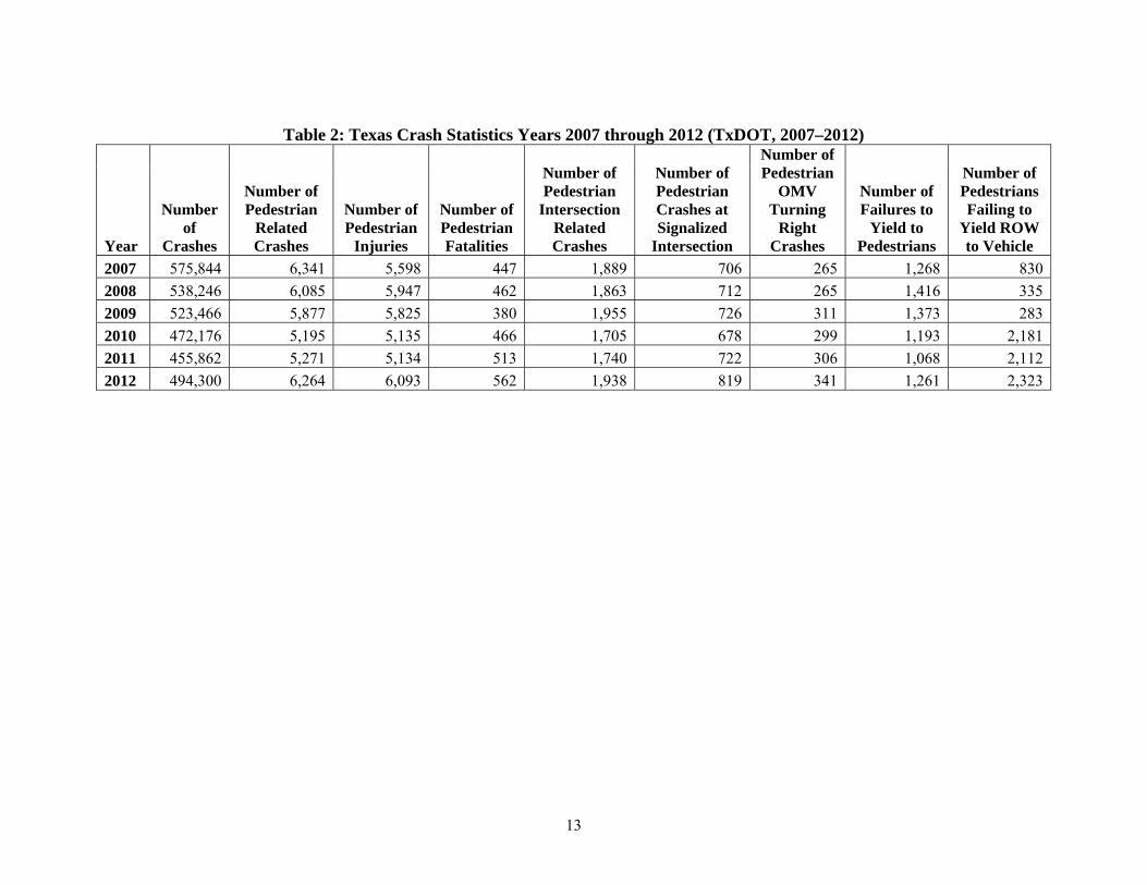
Table 2 shows the crash statistics in the state of Texas for years 2007 through 2012. The statistics show a recent upward trend in the total number of crashes as well as pedestrian-related incidents. Intersections account for almost a third of all pedestrian-related crashes, with an increase in the number of injuries, fatalities, and overall crashes since the year 2010. In particular, the number

12
of pedestrian-related crashes caused by right-turning vehicles has increased from 299 crashes in 2010 to 341 in 2012. Overall, the crash statistics imply that intersections are difficult for pedestrians to cross and must be designed with pedestrian safety in mind. Moreover, the table justifies the need to produce consistent design guidelines for right-turn slip lanes that improve the overall level of safety for pedestrians while curtailing the adverse effects of a ‘free’ right turn.
13
Table 2: Texas Crash Statistics Years 2007 through 2012 (TxDOT, 2007–2012)
Year
Number of
Crashes
Number of Pedestrian
Related Crashes
Number of Pedestrian
Injuries
Number of Pedestrian Fatalities
Number of Pedestrian
Intersection Related Crashes
Number of Pedestrian Crashes at Signalized
Intersection
Number of Pedestrian
OMV Turning
Right Crashes
Number of Failures to
Yield to Pedestrians
Number of Pedestrians Failing to
Yield ROW to Vehicle
2007 575,844 6,341 5,598 447 1,889 706 265 1,268 830
2008 538,246 6,085 5,947 462 1,863 712 265 1,416 335
2009 523,466 5,877 5,825 380 1,955 726 311 1,373 283
2010 472,176 5,195 5,135 466 1,705 678 299 1,193 2,181
2011 455,862 5,271 5,134 513 1,740 722 306 1,068 2,112
2012 494,300 6,264 6,093 562 1,938 819 341 1,261 2,323
14
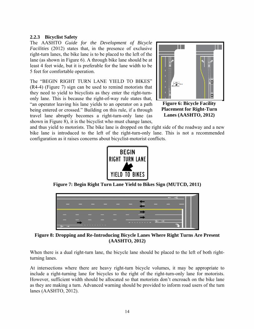
2.2.3 Bicyclist Safety The AASHTO Guide for the Development of Bicycle Facilities (2012) states that, in the presence of exclusive right-turn lanes, the bike lane is to be placed to the left of the lane (as shown in Figure 6). A through bike lane should be at least 4 feet wide, but it is preferable for the lane width to be 5 feet for comfortable operation.
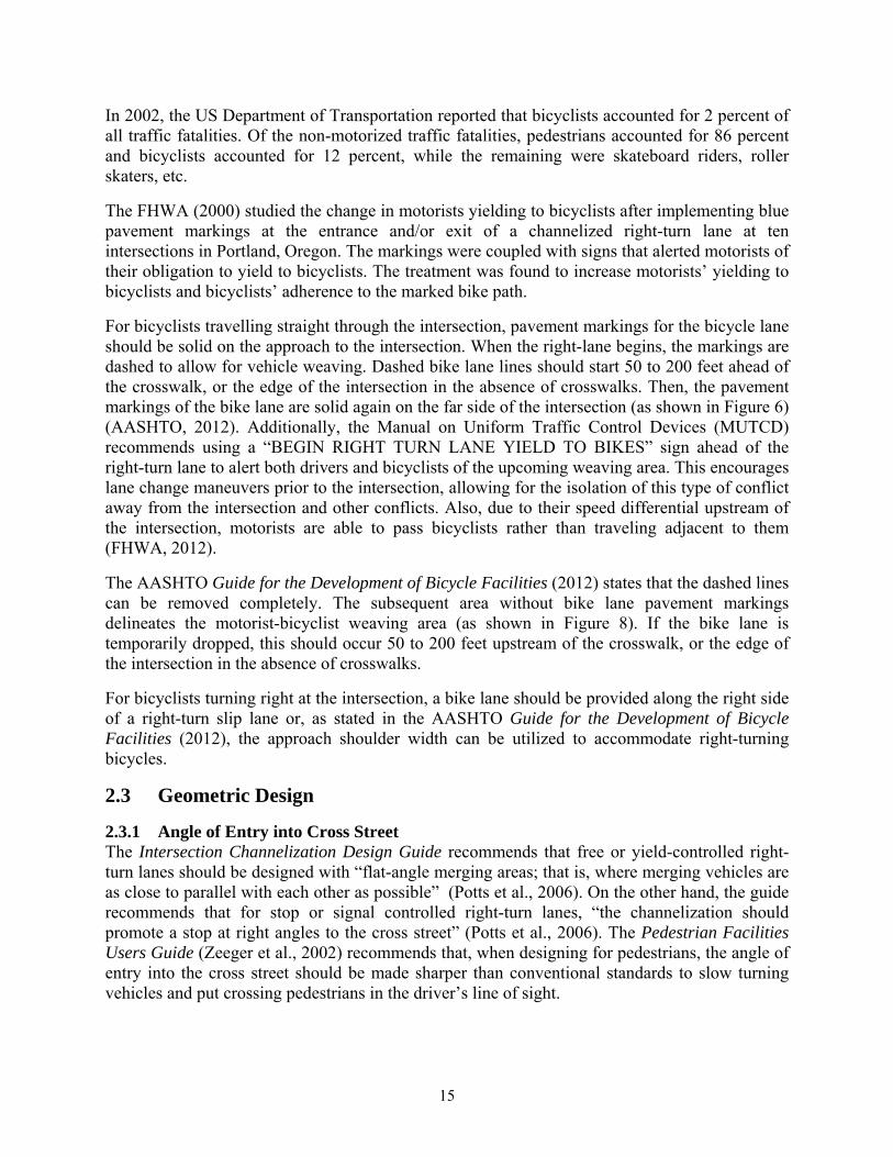
The “BEGIN RIGHT TURN LANE YIELD TO BIKES” (R4-4) (Figure 7) sign can be used to remind motorists that they need to yield to bicyclists as they enter the right-turn-only lane. This is because the right-of-way rule states that, “an operator leaving his lane yields to an operator on a path being entered or crossed.” Building on this rule, if a through travel lane abruptly becomes a right-turn-only lane (as shown in Figure 8), it is the bicyclist who must change lanes, and thus yield to motorists. The bike lane is dropped on the right side of the roadway and a new bike lane is introduced to the left of the right-turn-only lane. This is not a recommended configuration as it raises concerns about bicyclist-motorist conflicts.
Figure 7: Begin Right Turn Lane Yield to Bikes Sign (MUTCD, 2011)
Figure 8: Dropping and Re-Introducing Bicycle Lanes Where Right Turns Are Present (AASHTO, 2012)
When there is a dual right-turn lane, the bicycle lane should be placed to the left of both right-turning lanes.
At intersections where there are heavy right-turn bicycle volumes, it may be appropriate to include a right-turning lane for bicycles to the right of the right-turn-only lane for motorists. However, sufficient width should be allocated so that motorists don’t encroach on the bike lane as they are making a turn. Advanced warning should be provided to inform road users of the turn lanes (AASHTO, 2012).
Figure 6: Bicycle Facility Placement for Right-Turn Lanes (AASHTO, 2012)
15
In 2002, the US Department of Transportation reported that bicyclists accounted for 2 percent of all traffic fatalities. Of the non-motorized traffic fatalities, pedestrians accounted for 86 percent and bicyclists accounted for 12 percent, while the remaining were skateboard riders, roller skaters, etc.
The FHWA (2000) studied the change in motorists yielding to bicyclists after implementing blue pavement markings at the entrance and/or exit of a channelized right-turn lane at ten intersections in Portland, Oregon. The markings were coupled with signs that alerted motorists of their obligation to yield to bicyclists. The treatment was found to increase motorists’ yielding to bicyclists and bicyclists’ adherence to the marked bike path.
For bicyclists travelling straight through the intersection, pavement markings for the bicycle lane should be solid on the approach to the intersection. When the right-lane begins, the markings are dashed to allow for vehicle weaving. Dashed bike lane lines should start 50 to 200 feet ahead of the crosswalk, or the edge of the intersection in the absence of crosswalks. Then, the pavement markings of the bike lane are solid again on the far side of the intersection (as shown in Figure 6) (AASHTO, 2012). Additionally, the Manual on Uniform Traffic Control Devices (MUTCD) recommends using a “BEGIN RIGHT TURN LANE YIELD TO BIKES” sign ahead of the right-turn lane to alert both drivers and bicyclists of the upcoming weaving area. This encourages lane change maneuvers prior to the intersection, allowing for the isolation of this type of conflict away from the intersection and other conflicts. Also, due to their speed differential upstream of the intersection, motorists are able to pass bicyclists rather than traveling adjacent to them (FHWA, 2012).
The AASHTO Guide for the Development of Bicycle Facilities (2012) states that the dashed lines can be removed completely. The subsequent area without bike lane pavement markings delineates the motorist-bicyclist weaving area (as shown in Figure 8). If the bike lane is temporarily dropped, this should occur 50 to 200 feet upstream of the crosswalk, or the edge of the intersection in the absence of crosswalks.
For bicyclists turning right at the intersection, a bike lane should be provided along the right side of a right-turn slip lane or, as stated in the AASHTO Guide for the Development of Bicycle Facilities (2012), the approach shoulder width can be utilized to accommodate right-turning bicycles.
2.3 Geometric Design
2.3.1 Angle of Entry into Cross Street The Intersection Channelization Design Guide recommends that free or yield-controlled right-turn lanes should be designed with “flat-angle merging areas; that is, where merging vehicles are as close to parallel with each other as possible” (Potts et al., 2006). On the other hand, the guide recommends that for stop or signal controlled right-turn lanes, “the channelization should promote a stop at right angles to the cross street” (Potts et al., 2006). The Pedestrian Facilities Users Guide (Zeeger et al., 2002) recommends that, when designing for pedestrians, the angle of entry into the cross street should be made sharper than conventional standards to slow turning vehicles and put crossing pedestrians in the driver’s line of sight.
16
The Pedestrian Safety Guide and Countermeasure Selection System (Zeeger et al., 2013) recommends having the angle at which the right-turn intersects the cross street closer to 110 percent than 140 percent. This allows for good visibility and reduces turning speeds to 14–18 mph. This reduction in speed results in improved pedestrian safety. If the crosswalk is placed upstream, drivers can focus their attention on pedestrians before crossing traffic. Also, placing the crosswalk upstream may reduce the pedestrian crossing distance (Potts et al., 2006d).
2.3.2 Turning Radius and Turning Angle The design of the curb radius influences the lane width and consequently the pedestrian crossing distance. Curb radii should be designed in such a way that they accommodate the design vehicle but, at the same time, do not impose a danger to pedestrians by facilitating faster turns (Potts et al., 2006d). According to Umbs (2010), the use of small corner radii allow for two pedestrian ramps, shorter crosswalks, and direct travel paths.
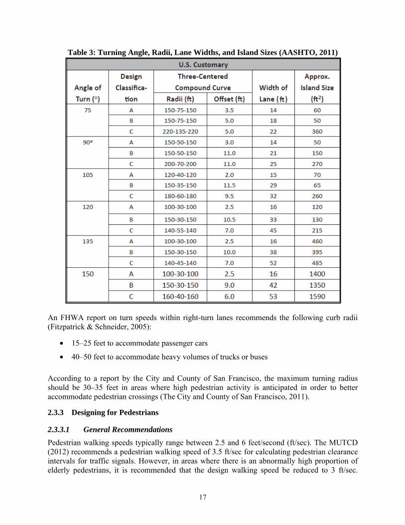
Table 3 shows the recommended turning radii, lane widths, and island sizes based on the angle of turn and the vehicle mix. Note that the turning radii, lane widths, and island sizes for design classification C are significantly larger than those for design classification A due to the need to accommodate more buses and trucks in the traffic mix.
Classes A, B, and C are defined according to the vehicle mix, with passenger cars comprising the majority for A and buses and trucks comprising the majority for C (AASHTO, 2011).
17
Table 3: Turning Angle, Radii, Lane Widths, and Island Sizes (AASHTO, 2011)
An FHWA report on turn speeds within right-turn lanes recommends the following curb radii (Fitzpatrick & Schneider, 2005):
• 15–25 feet to accommodate passenger cars
• 40–50 feet to accommodate heavy volumes of trucks or buses
According to a report by the City and County of San Francisco, the maximum turning radius should be 30–35 feet in areas where high pedestrian activity is anticipated in order to better accommodate pedestrian crossings (The City and County of San Francisco, 2011).
2.3.3 Designing for Pedestrians
2.3.3.1 General Recommendations
Pedestrian walking speeds typically range between 2.5 and 6 feet/second (ft/sec). The MUTCD (2012) recommends a pedestrian walking speed of 3.5 ft/sec for calculating pedestrian clearance intervals for traffic signals. However, in areas where there is an abnormally high proportion of elderly pedestrians, it is recommended that the design walking speed be reduced to 3 ft/sec.
18
Walking speed is typically affected by age, physical condition, grade, temperature, time of day, and trip purpose (Potts et al., 2006d). In general, audible pedestrian signals have been found to reduce the time needed for a pedestrian to cross a street.
Right-turn slip lanes allow for high speed turning movements. Therefore, to reduce the threat to pedestrians, the right-turn lane width must be kept to a minimum, though enough to accommodate the design vehicle. Also, the angle of entry into the cross street must be as close as feasible to 90 degrees (AASHTO, 2004).
The size of the median/crossing island should be directly related to the expected volume of pedestrians and bicyclists expected to use these roadway facilities. As the activity increases, so should the size of these roadway features (AASHTO, 2004).
The width of a recently built crossing island should be at least 6 feet to allow for wheelchair access, as well as for sufficient pedestrian storage separated from the face of curb. The island/median size can be increased depending on expected pedestrian volumes and desired level of service criteria. Reconstruction projects that impact existing medians should include widening them to at least 6 feet. If possible, islands/medians should be 8 feet wide to accommodate groups of pedestrian, bicycles, and mobility aids such as wheelchairs and scooters. If there is not sufficient space for the crossing island, consider narrowing lanes to 11 feet or even 10 feet in order to provide the needed space. However, this narrowing should be preceded by considerations of traffic volume, vehicle mix, speed, and the presence of bicyclists (as discussed in Section 2.3.8). If widening the median is not practical, the crossing or cut-through width can be increased to allow for more storage space for pedestrians and bicycles within the median. At a minimum, the clear width should be maintained in the cut-through section (AASHTO, 2004).
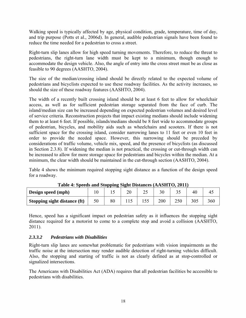
Table 4 shows the minimum required stopping sight distance as a function of the design speed for a roadway.
Table 4: Speeds and Stopping Sight Distances (AASHTO, 2011)
Design speed (mph) 10 15 20 25 30 35 40 45
Stopping sight distance (ft) 50 80 115 155 200 250 305 360
Hence, speed has a significant impact on pedestrian safety as it influences the stopping sight distance required for a motorist to come to a complete stop and avoid a collision (AASHTO, 2011).
2.3.3.2 Pedestrians with Disabilities
Right-turn slip lanes are somewhat problematic for pedestrians with vision impairments as the traffic noise at the intersection may render audible detection of right-turning vehicles difficult. Also, the stopping and starting of traffic is not as clearly defined as at stop-controlled or signalized intersections.
The Americans with Disabilities Act (ADA) requires that all pedestrian facilities be accessible to pedestrians with disabilities.
19
R305.7 Channelized Turn Lanes at Intersections. Where pedestrian crosswalks are provided at multi-lane right or left channelized turn lanes at intersections with pedestrian signal indications, a pedestrian activated signal complying with R306 shall be provided. Advisory R305.7 Channelized Turn Lanes at Intersections. Accessible pedestrian signal devices installed at splitter and ‘pork chop’ islands must be carefully located and separated so that signal spillover does not give conflicting information about which crossing has the WALK indication displayed. Additional guidance on signal types is provided in Advisory R305.6.2 (Architectural and Transportation Barriers Compliance Board, 2005).
Interviews with orientation and mobility (O&M) specialists, as part of NCHRP 3-89 project, revealed that the lack of consistency in intersection geometry, crosswalk location, and type of traffic control devices makes it difficult to educate pedestrians with vision impairments on crossing right-turn slip lanes. They reported that the presence of acceleration lanes downstream of the turn makes the crossing of visually impaired people virtually impossible because of the ability of drivers to make the turn at high speeds. In fact, uncontrolled slip lanes that connect with exclusive downstream lanes are typically discouraged in areas where pedestrians are expected to be present (The City and County of San Francisco, 2011). Also, as to the choice of island type, O&M specialists agreed that painted islands don’t serve their clients since they don’t provide true refuge for pedestrians. They stated that raised islands with sloped cut-through areas are efficient for providing visually impaired pedestrians a cue that they have reached an island. Also, they recommend avoiding landscaping and low signage within the islands (Potts et al., 2011).
The AASHTO Guide for Planning, Design, and Operation of Pedestrian Facilities (2004) recommends that the surface quality be suitable for all kinds of pedestrians, including those with wheelchairs, scooters, walking aids and prosthetics. Cross slopes that are steeper than 2 percent may prove problematic as they impact the stability and control of wheelchairs and scooters. Passing space must be sufficient to accommodate wheelchairs (of varying kinds) and scooters. Moreover, signal timing must take into account different pedestrians, including those with walking aids, prosthetics and hearing impairments.
Pedestrians that rely on walking canes can benefit from tactile surfaces that signal a “stop” message. Detectable warning devices should be installed in accordance with ADA Accessibility Guidelines. Pedestrians that rely on dogs as their guides can benefit from a straight line of travel from the edge of the sidewalk to the opposite curb, as they won’t have to deviate from their paths (AASHTO, 2011).
Information that is useful to pedestrians with vision impairments include large printed and raised text messages, accessible pedestrian signals, guide strips that assist pedestrians with wayfinding, warning surfaces, physical barriers, and adequate lighting (AASHTO, 2004). The MUTCD (FHWA, 2012) mandates that all new pedestrian signal indications display symbolic messages rather than lettered messages as the former better accommodate children and pedestrians with cognitive impairments (per MUTCD Section 4E.04).
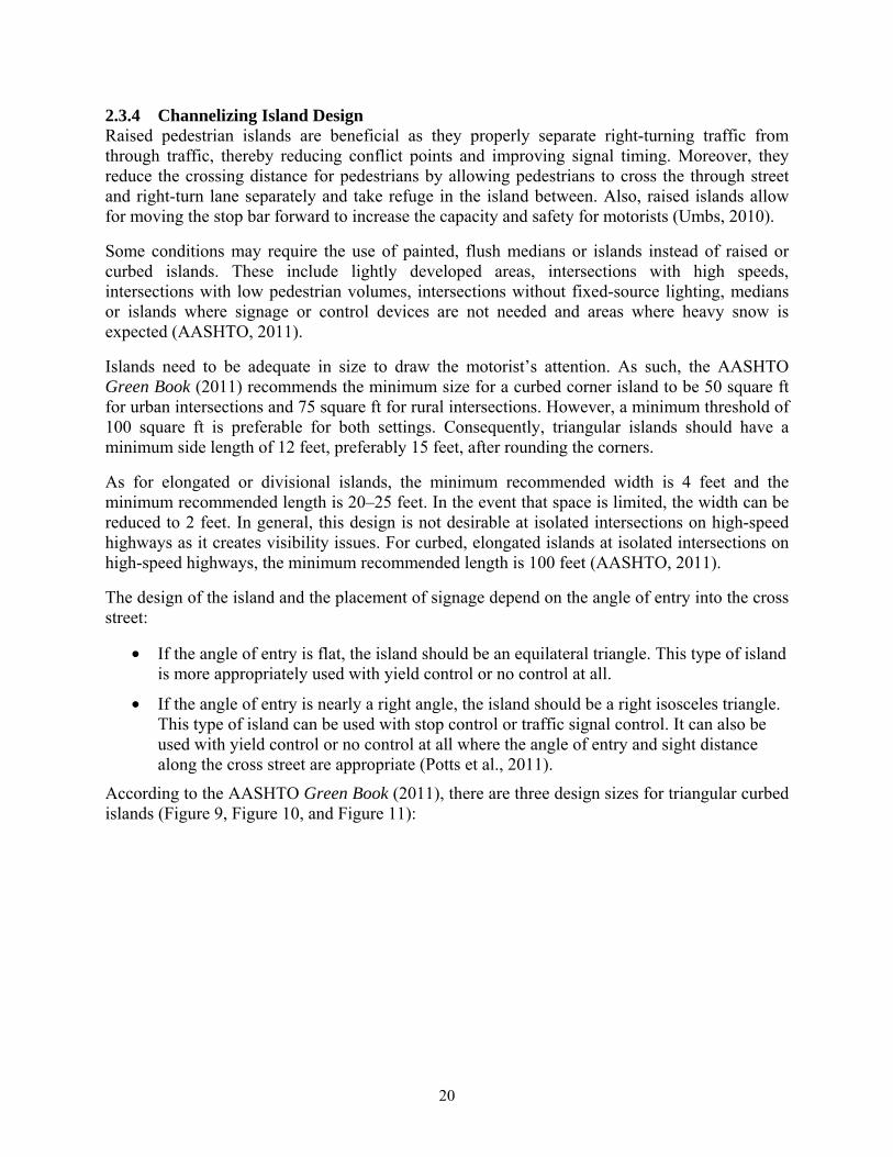
20
2.3.4 Channelizing Island Design Raised pedestrian islands are beneficial as they properly separate right-turning traffic from through traffic, thereby reducing conflict points and improving signal timing. Moreover, they reduce the crossing distance for pedestrians by allowing pedestrians to cross the through street and right-turn lane separately and take refuge in the island between. Also, raised islands allow for moving the stop bar forward to increase the capacity and safety for motorists (Umbs, 2010).
Some conditions may require the use of painted, flush medians or islands instead of raised or curbed islands. These include lightly developed areas, intersections with high speeds, intersections with low pedestrian volumes, intersections without fixed-source lighting, medians or islands where signage or control devices are not needed and areas where heavy snow is expected (AASHTO, 2011).
Islands need to be adequate in size to draw the motorist’s attention. As such, the AASHTO Green Book (2011) recommends the minimum size for a curbed corner island to be 50 square ft for urban intersections and 75 square ft for rural intersections. However, a minimum threshold of 100 square ft is preferable for both settings. Consequently, triangular islands should have a minimum side length of 12 feet, preferably 15 feet, after rounding the corners.
As for elongated or divisional islands, the minimum recommended width is 4 feet and the minimum recommended length is 20–25 feet. In the event that space is limited, the width can be reduced to 2 feet. In general, this design is not desirable at isolated intersections on high-speed highways as it creates visibility issues. For curbed, elongated islands at isolated intersections on high-speed highways, the minimum recommended length is 100 feet (AASHTO, 2011).
The design of the island and the placement of signage depend on the angle of entry into the cross street:
• If the angle of entry is flat, the island should be an equilateral triangle. This type of island is more appropriately used with yield control or no control at all.
• If the angle of entry is nearly a right angle, the island should be a right isosceles triangle. This type of island can be used with stop control or traffic signal control. It can also be used with yield control or no control at all where the angle of entry and sight distance along the cross street are appropriate (Potts et al., 2011).
According to the AASHTO Green Book (2011), there are three design sizes for triangular curbed islands (Figure 9, Figure 10, and Figure 11):
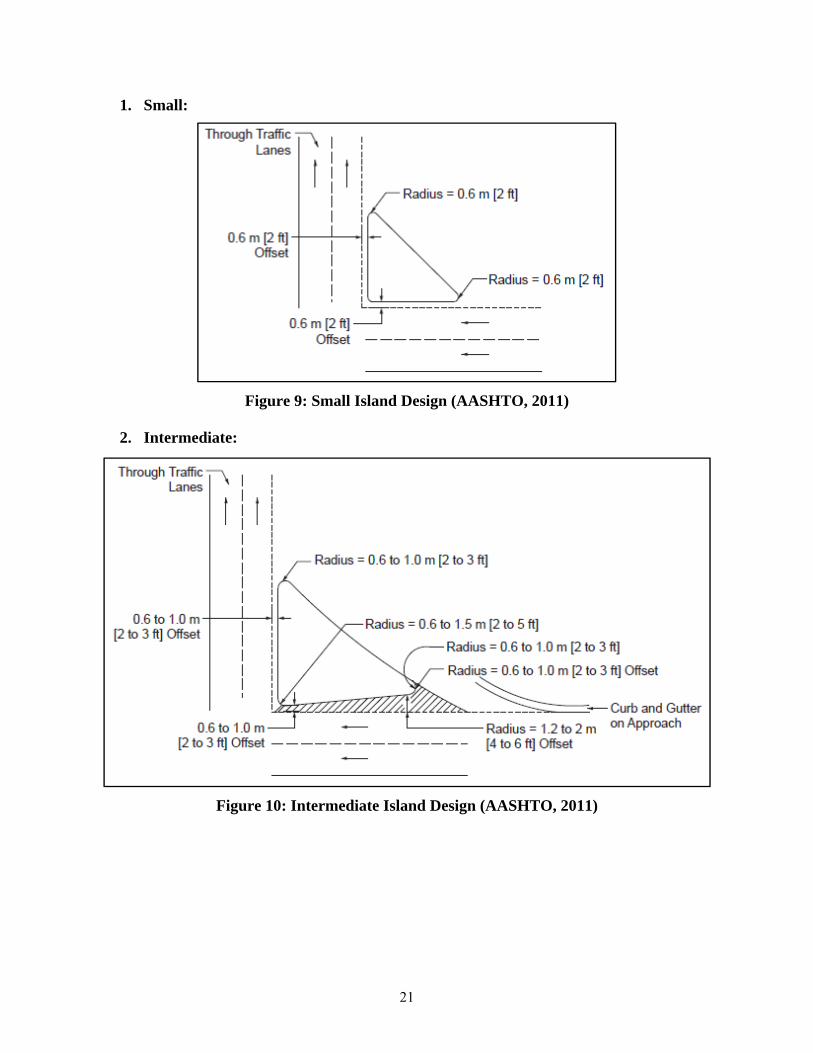
21
1. Small:
Figure 9: Small Island Design (AASHTO, 2011)
2. Intermediate:
Figure 10: Intermediate Island Design (AASHTO, 2011)
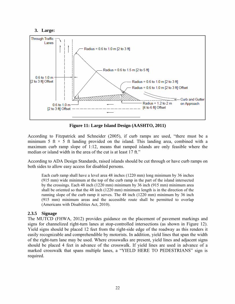
22
3. Large:
Figure 11: Large Island Design (AASHTO, 2011) According to Fitzpatrick and Schneider (2005), if curb ramps are used, “there must be a minimum 5 ft × 5 ft landing provided on the island. This landing area, combined with a maximum curb ramp slope of 1:12, means that ramped islands are only feasible where the median or island width in the area of the cut is at least 17 ft.”
According to ADA Design Standards, raised islands should be cut through or have curb ramps on both sides to allow easy access for disabled persons.
Each curb ramp shall have a level area 48 inches (1220 mm) long minimum by 36 inches (915 mm) wide minimum at the top of the curb ramp in the part of the island intersected by the crossings. Each 48 inch (1220 mm) minimum by 36 inch (915 mm) minimum area shall be oriented so that the 48 inch (1220 mm) minimum length is in the direction of the running slope of the curb ramp it serves. The 48 inch (1220 mm) minimum by 36 inch (915 mm) minimum areas and the accessible route shall be permitted to overlap (Americans with Disabilities Act, 2010).
2.3.5 Signage The MUTCD (FHWA, 2012) provides guidance on the placement of pavement markings and signs for channelized right-turn lanes at stop-controlled intersections (as shown in Figure 12). Yield signs should be placed 12 feet from the right-side edge of the roadway as this renders it easily recognizable and comprehendible by motorists. In addition, yield lines that span the width of the right-turn lane may be used. Where crosswalks are present, yield lines and adjacent signs should be placed 4 feet in advance of the crosswalk. If yield lines are used in advance of a marked crosswalk that spans multiple lanes, a “YIELD HERE TO PEDESTRIANS” sign is required.
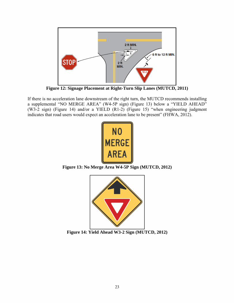
23
Figure 12: Signage Placement at Right-Turn Slip Lanes (MUTCD, 2011)
If there is no acceleration lane downstream of the right turn, the MUTCD recommends installing a supplemental “NO MERGE AREA” (W4-5P sign) (Figure 13) below a “YIELD AHEAD” (W3-2 sign) (Figure 14) and/or a YIELD (R1-2) (Figure 15) “when engineering judgment indicates that road users would expect an acceleration lane to be present” (FHWA, 2012).
Figure 13: No Merge Area W4-5P Sign (MUTCD, 2012)
Figure 14: Yield Ahead W3-2 Sign (MUTCD, 2012)
24
Figure 15: Yield R1-2 Sign (MUTCD, 2012)
2.3.6 Lighting and Markings Curbed islands may be difficult to spot at night if insufficient lighting is present. Therefore, where curbed islands are used, the intersection should have “fixed-source lighting or appropriate delineation such as curb-top reflectors.” Consistency is important for conforming to motorist expectations. It is recommended to use the same design and illumination features at similar intersections (AASHTO, 2011).
The MUTCD (FHWA, 2012) provides additional information regarding the delineation of channelizing islands. When their use is deemed appropriate, pavement markings, curb markings, and colored pavement should consist of retroreflective white or yellow material depending on the direction(s) of travel separated. Retroreflective material is important for delineating the alignment of the lane separation on the approach as well as the edge of the island for travel at night or when conditions limit visibility. Delineators or other channelizing devices may be used and, if installed, must be consistent in color with any adjacent pavement markings to properly designate the direction(s) of travel separated.
2.3.7 Crosswalks NCHRP Report 3-72 (2006d) identifies six alternative crosswalk configurations:
1. Marked crosswalk located at the upstream end of the right turn and parallel to the sidewalk:
This approach (as shown in Figure 16) clearly defines the pedestrian right-of-way and allows for drivers to see pedestrians crossing upstream of the merge with the cross street, reducing potential conflicts. Furthermore, pedestrians walking on the sidewalk can cross the right-turning lane on a direct path. However, this method increases the crossing distance for pedestrians, does not provide a direct path for pedestrians walking on the cross street, forces pedestrians to cross the right-turning lane parallel to street traffic, renders the provision of pedestrian signalization and curb ramps rather difficult
Figure 16: Marked Crosswalk Located
Upstream and Parallel to Sidewalk (adapted from
NCHRP 3-72, 2006d)
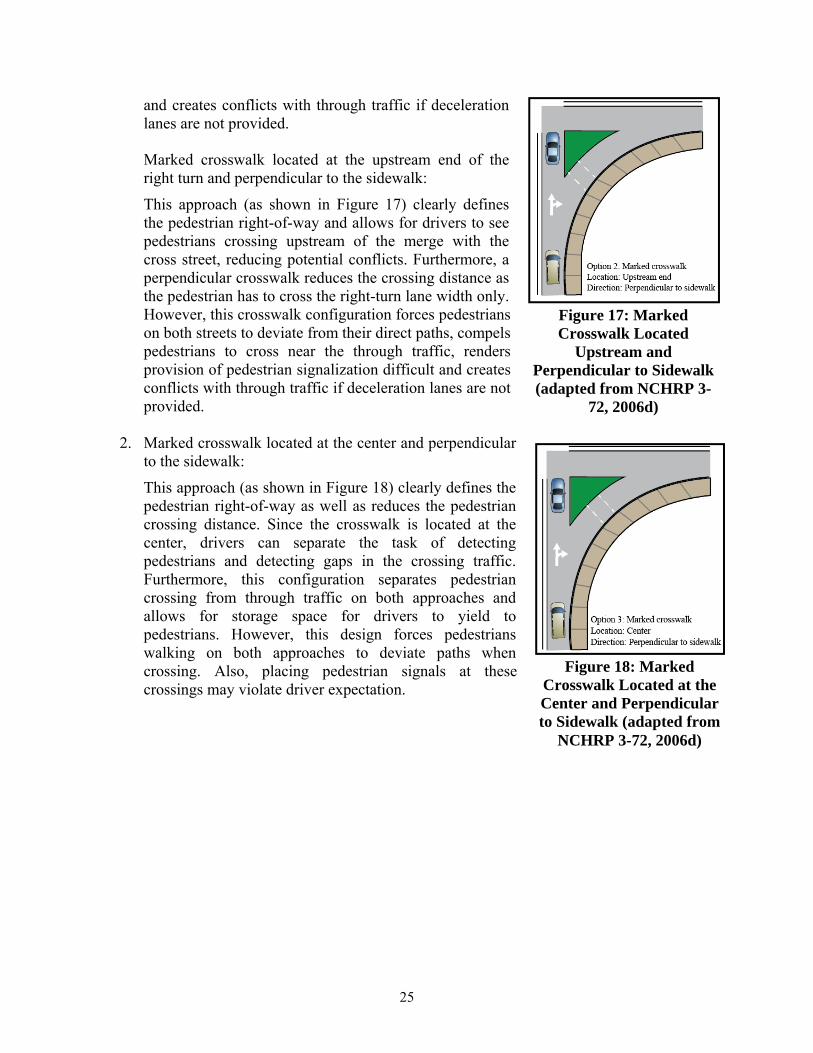
25
and creates conflicts with through traffic if deceleration lanes are not provided.
Marked crosswalk located at the upstream end of the right turn and perpendicular to the sidewalk:
This approach (as shown in Figure 17) clearly defines the pedestrian right-of-way and allows for drivers to see pedestrians crossing upstream of the merge with the cross street, reducing potential conflicts. Furthermore, a perpendicular crosswalk reduces the crossing distance as the pedestrian has to cross the right-turn lane width only. However, this crosswalk configuration forces pedestrians on both streets to deviate from their direct paths, compels pedestrians to cross near the through traffic, renders provision of pedestrian signalization difficult and creates conflicts with through traffic if deceleration lanes are not provided.
2. Marked crosswalk located at the center and perpendicular to the sidewalk:
This approach (as shown in Figure 18) clearly defines the pedestrian right-of-way as well as reduces the pedestrian crossing distance. Since the crosswalk is located at the center, drivers can separate the task of detecting pedestrians and detecting gaps in the crossing traffic. Furthermore, this configuration separates pedestrian crossing from through traffic on both approaches and allows for storage space for drivers to yield to pedestrians. However, this design forces pedestrians walking on both approaches to deviate paths when crossing. Also, placing pedestrian signals at these crossings may violate driver expectation.
Figure 17: Marked Crosswalk Located
Upstream and Perpendicular to Sidewalk (adapted from NCHRP 3-
72, 2006d)
Figure 18: Marked Crosswalk Located at the Center and Perpendicular to Sidewalk (adapted from
NCHRP 3-72, 2006d)
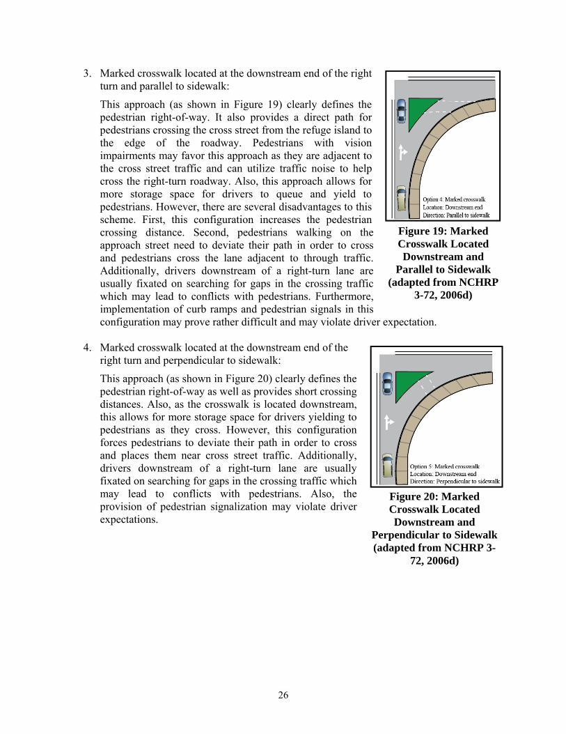
26
3. Marked crosswalk located at the downstream end of the right turn and parallel to sidewalk:
This approach (as shown in Figure 19) clearly defines the pedestrian right-of-way. It also provides a direct path for pedestrians crossing the cross street from the refuge island to the edge of the roadway. Pedestrians with vision impairments may favor this approach as they are adjacent to the cross street traffic and can utilize traffic noise to help cross the right-turn roadway. Also, this approach allows for more storage space for drivers to queue and yield to pedestrians. However, there are several disadvantages to this scheme. First, this configuration increases the pedestrian crossing distance. Second, pedestrians walking on the approach street need to deviate their path in order to cross and pedestrians cross the lane adjacent to through traffic. Additionally, drivers downstream of a right-turn lane are usually fixated on searching for gaps in the crossing traffic which may lead to conflicts with pedestrians. Furthermore, implementation of curb ramps and pedestrian signals in this configuration may prove rather difficult and may violate driver expectation.
4. Marked crosswalk located at the downstream end of the
right turn and perpendicular to sidewalk:
This approach (as shown in Figure 20) clearly defines the pedestrian right-of-way as well as provides short crossing distances. Also, as the crosswalk is located downstream, this allows for more storage space for drivers yielding to pedestrians as they cross. However, this configuration forces pedestrians to deviate their path in order to cross and places them near cross street traffic. Additionally, drivers downstream of a right-turn lane are usually fixated on searching for gaps in the crossing traffic which may lead to conflicts with pedestrians. Also, the provision of pedestrian signalization may violate driver expectations.
Figure 19: Marked Crosswalk Located Downstream and
Parallel to Sidewalk (adapted from NCHRP
3-72, 2006d)
Figure 20: Marked Crosswalk Located Downstream and
Perpendicular to Sidewalk (adapted from NCHRP 3-
72, 2006d)
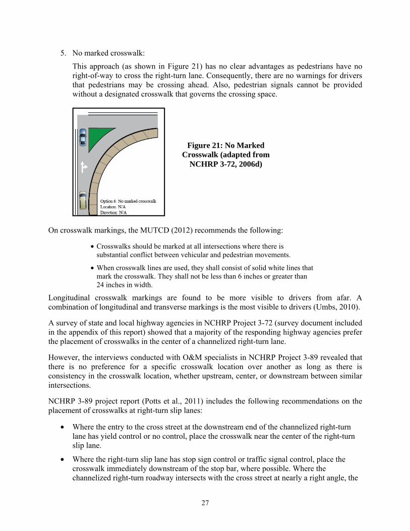
27
5. No marked crosswalk:
This approach (as shown in Figure 21) has no clear advantages as pedestrians have no right-of-way to cross the right-turn lane. Consequently, there are no warnings for drivers that pedestrians may be crossing ahead. Also, pedestrian signals cannot be provided without a designated crosswalk that governs the crossing space.
On crosswalk markings, the MUTCD (2012) recommends the following:
• Crosswalks should be marked at all intersections where there is substantial conflict between vehicular and pedestrian movements.
• When crosswalk lines are used, they shall consist of solid white lines that mark the crosswalk. They shall not be less than 6 inches or greater than 24 inches in width.
Longitudinal crosswalk markings are found to be more visible to drivers from afar. A combination of longitudinal and transverse markings is the most visible to drivers (Umbs, 2010).
A survey of state and local highway agencies in NCHRP Project 3-72 (survey document included in the appendix of this report) showed that a majority of the responding highway agencies prefer the placement of crosswalks in the center of a channelized right-turn lane.
However, the interviews conducted with O&M specialists in NCHRP Project 3-89 revealed that there is no preference for a specific crosswalk location over another as long as there is consistency in the crosswalk location, whether upstream, center, or downstream between similar intersections.
NCHRP 3-89 project report (Potts et al., 2011) includes the following recommendations on the placement of crosswalks at right-turn slip lanes:
• Where the entry to the cross street at the downstream end of the channelized right-turn lane has yield control or no control, place the crosswalk near the center of the right-turn slip lane.
• Where the right-turn slip lane has stop sign control or traffic signal control, place the crosswalk immediately downstream of the stop bar, where possible. Where the channelized right-turn roadway intersects with the cross street at nearly a right angle, the
Figure 21: No Marked Crosswalk (adapted from
NCHRP 3-72, 2006d)
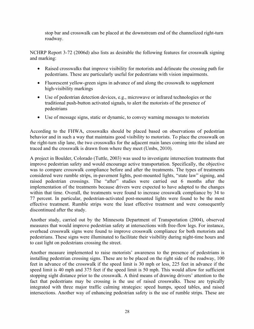
28
stop bar and crosswalk can be placed at the downstream end of the channelized right-turn roadway.
NCHRP Report 3-72 (2006d) also lists as desirable the following features for crosswalk signing and marking:
• Raised crosswalks that improve visibility for motorists and delineate the crossing path for pedestrians. These are particularly useful for pedestrians with vision impairments.
• Fluorescent yellow-green signs in advance of and along the crosswalk to supplement high-visibility markings
• Use of pedestrian detection devices, e.g., microwave or infrared technologies or the traditional push-button activated signals, to alert the motorists of the presence of pedestrians
• Use of message signs, static or dynamic, to convey warning messages to motorists
According to the FHWA, crosswalks should be placed based on observations of pedestrian behavior and in such a way that maintains good visibility to motorists. To place the crosswalk on the right-turn slip lane, the two crosswalks for the adjacent main lanes coming into the island are traced and the crosswalk is drawn from where they meet (Umbs, 2010).
A project in Boulder, Colorado (Tuttle, 2003) was used to investigate intersection treatments that improve pedestrian safety and would encourage active transportation. Specifically, the objective was to compare crosswalk compliance before and after the treatments. The types of treatments considered were rumble strips, in-pavement lights, post-mounted lights, “state law” signing, and raised pedestrian crossings. The “after” studies were carried out 6 months after the implementation of the treatments because drivers were expected to have adapted to the changes within that time. Overall, the treatments were found to increase crosswalk compliance by 34 to 77 percent. In particular, pedestrian-activated post-mounted lights were found to be the most effective treatment. Rumble strips were the least effective treatment and were consequently discontinued after the study.
Another study, carried out by the Minnesota Department of Transportation (2004), observed measures that would improve pedestrian safety at intersections with free-flow legs. For instance, overhead crosswalk signs were found to improve crosswalk compliance for both motorists and pedestrians. These signs were illuminated to facilitate their visibility during night-time hours and to cast light on pedestrians crossing the street.
Another measure implemented to raise motorists’ awareness to the presence of pedestrians is installing pedestrian crossing signs. These are to be placed on the right side of the roadway, 100 feet in advance of the crosswalk if the speed limit is 30 mph or less, 225 feet in advance if the speed limit is 40 mph and 375 feet if the speed limit is 50 mph. This would allow for sufficient stopping sight distance prior to the crosswalk. A third means of drawing drivers’ attention to the fact that pedestrians may be crossing is the use of raised crosswalks. These are typically integrated with three major traffic calming strategies: speed humps, speed tables, and raised intersections. Another way of enhancing pedestrian safety is the use of rumble strips. These are
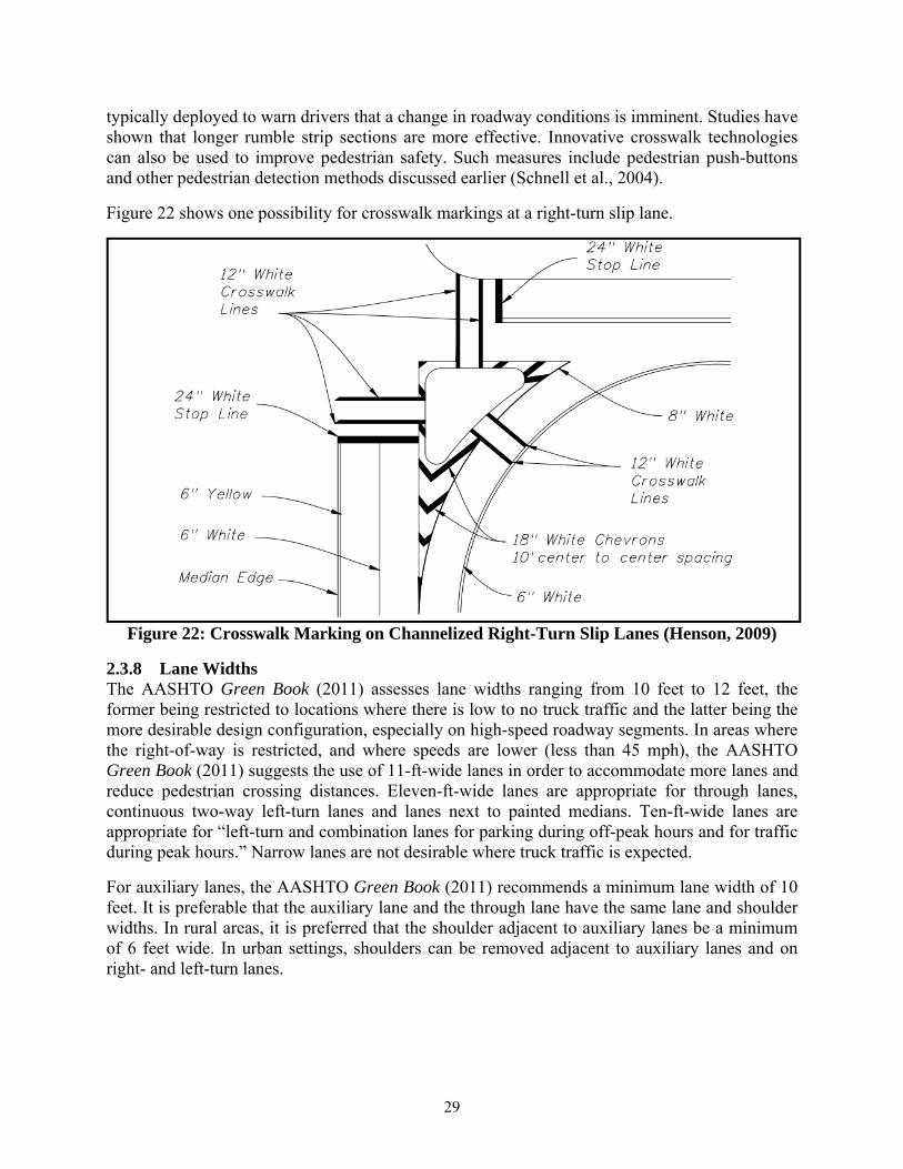
29
typically deployed to warn drivers that a change in roadway conditions is imminent. Studies have shown that longer rumble strip sections are more effective. Innovative crosswalk technologies can also be used to improve pedestrian safety. Such measures include pedestrian push-buttons and other pedestrian detection methods discussed earlier (Schnell et al., 2004).
Figure 22 shows one possibility for crosswalk markings at a right-turn slip lane.
Figure 22: Crosswalk Marking on Channelized Right-Turn Slip Lanes (Henson, 2009)
2.3.8 Lane Widths The AASHTO Green Book (2011) assesses lane widths ranging from 10 feet to 12 feet, the former being restricted to locations where there is low to no truck traffic and the latter being the more desirable design configuration, especially on high-speed roadway segments. In areas where the right-of-way is restricted, and where speeds are lower (less than 45 mph), the AASHTO Green Book (2011) suggests the use of 11-ft-wide lanes in order to accommodate more lanes and reduce pedestrian crossing distances. Eleven-ft-wide lanes are appropriate for through lanes, continuous two-way left-turn lanes and lanes next to painted medians. Ten-ft-wide lanes are appropriate for “left-turn and combination lanes for parking during off-peak hours and for traffic during peak hours.” Narrow lanes are not desirable where truck traffic is expected.
For auxiliary lanes, the AASHTO Green Book (2011) recommends a minimum lane width of 10 feet. It is preferable that the auxiliary lane and the through lane have the same lane and shoulder widths. In rural areas, it is preferred that the shoulder adjacent to auxiliary lanes be a minimum of 6 feet wide. In urban settings, shoulders can be removed adjacent to auxiliary lanes and on right- and left-turn lanes.
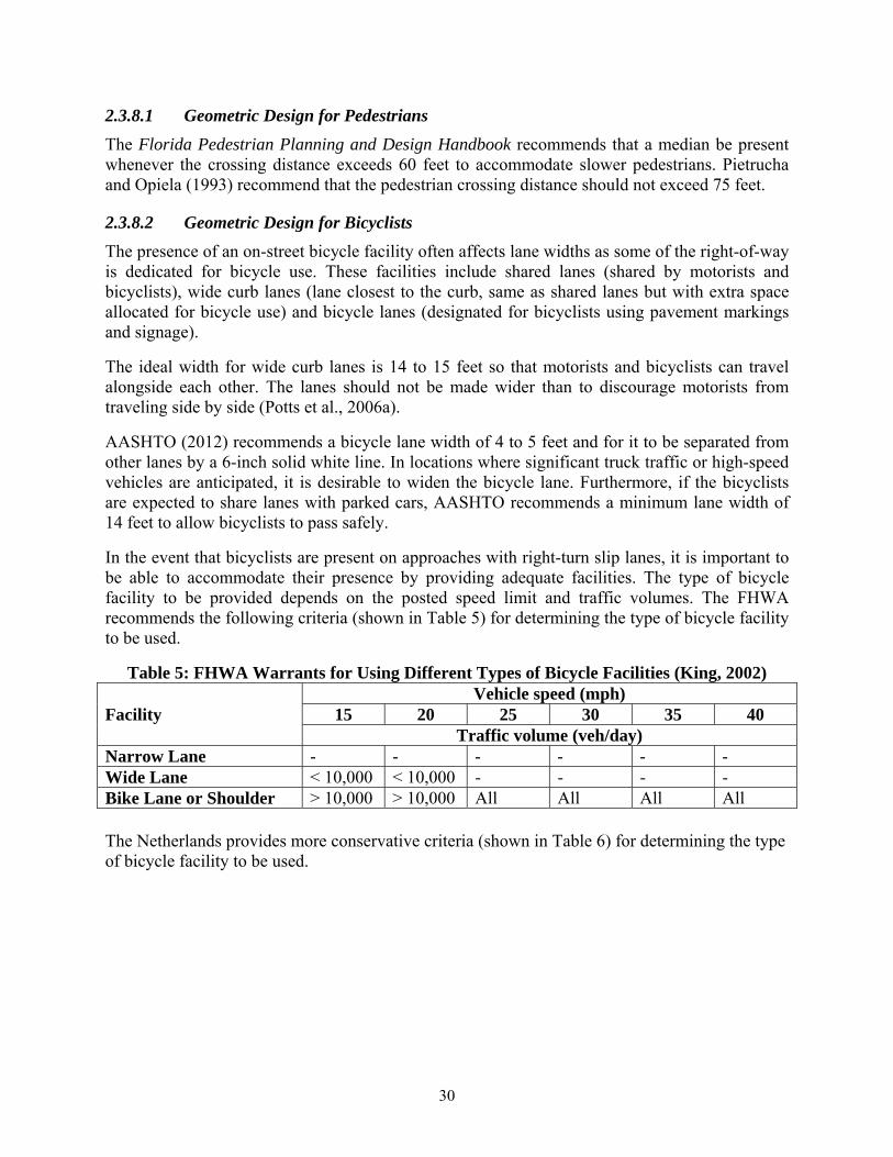
30
2.3.8.1 Geometric Design for Pedestrians
The Florida Pedestrian Planning and Design Handbook recommends that a median be present whenever the crossing distance exceeds 60 feet to accommodate slower pedestrians. Pietrucha and Opiela (1993) recommend that the pedestrian crossing distance should not exceed 75 feet.
2.3.8.2 Geometric Design for Bicyclists
The presence of an on-street bicycle facility often affects lane widths as some of the right-of-way is dedicated for bicycle use. These facilities include shared lanes (shared by motorists and bicyclists), wide curb lanes (lane closest to the curb, same as shared lanes but with extra space allocated for bicycle use) and bicycle lanes (designated for bicyclists using pavement markings and signage).
The ideal width for wide curb lanes is 14 to 15 feet so that motorists and bicyclists can travel alongside each other. The lanes should not be made wider than to discourage motorists from traveling side by side (Potts et al., 2006a).
AASHTO (2012) recommends a bicycle lane width of 4 to 5 feet and for it to be separated from other lanes by a 6-inch solid white line. In locations where significant truck traffic or high-speed vehicles are anticipated, it is desirable to widen the bicycle lane. Furthermore, if the bicyclists are expected to share lanes with parked cars, AASHTO recommends a minimum lane width of 14 feet to allow bicyclists to pass safely.
In the event that bicyclists are present on approaches with right-turn slip lanes, it is important to be able to accommodate their presence by providing adequate facilities. The type of bicycle facility to be provided depends on the posted speed limit and traffic volumes. The FHWA recommends the following criteria (shown in Table 5) for determining the type of bicycle facility to be used.
Table 5: FHWA Warrants for Using Different Types of Bicycle Facilities (King, 2002)
Facility Vehicle speed (mph)
15 20 25 30 35 40 Traffic volume (veh/day)
Narrow Lane - - - - - - Wide Lane < 10,000 < 10,000 - - - - Bike Lane or Shoulder > 10,000 > 10,000 All All All All
The Netherlands provides more conservative criteria (shown in Table 6) for determining the type of bicycle facility to be used.
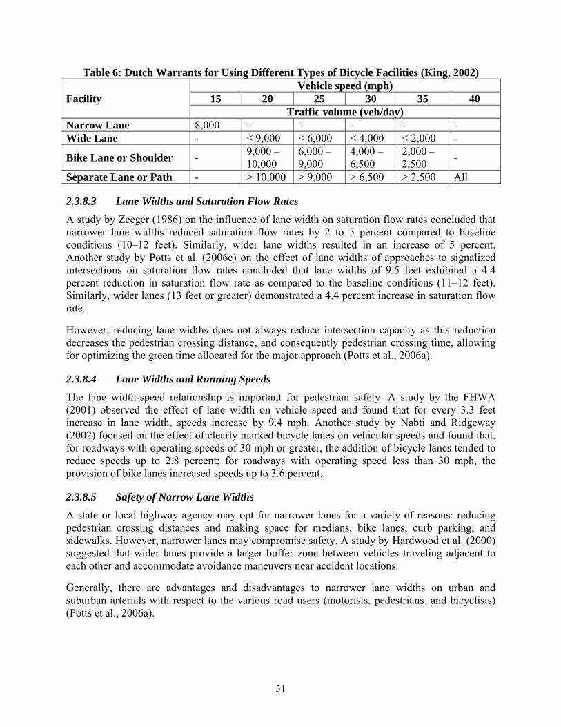
31
Table 6: Dutch Warrants for Using Different Types of Bicycle Facilities (King, 2002)
Facility Vehicle speed (mph)
15 20 25 30 35 40 Traffic volume (veh/day)
Narrow Lane 8,000 - - - - - Wide Lane - < 9,000 < 6,000 < 4,000 < 2,000 -
Bike Lane or Shoulder - 9,000 – 10,000
6,000 – 9,000
4,000 – 6,500
2,000 – 2,500
-
Separate Lane or Path - > 10,000 > 9,000 > 6,500 > 2,500 All
2.3.8.3 Lane Widths and Saturation Flow Rates
A study by Zeeger (1986) on the influence of lane width on saturation flow rates concluded that narrower lane widths reduced saturation flow rates by 2 to 5 percent compared to baseline conditions (10–12 feet). Similarly, wider lane widths resulted in an increase of 5 percent. Another study by Potts et al. (2006c) on the effect of lane widths of approaches to signalized intersections on saturation flow rates concluded that lane widths of 9.5 feet exhibited a 4.4 percent reduction in saturation flow rate as compared to the baseline conditions (11–12 feet). Similarly, wider lanes (13 feet or greater) demonstrated a 4.4 percent increase in saturation flow rate.
However, reducing lane widths does not always reduce intersection capacity as this reduction decreases the pedestrian crossing distance, and consequently pedestrian crossing time, allowing for optimizing the green time allocated for the major approach (Potts et al., 2006a).
2.3.8.4 Lane Widths and Running Speeds
The lane width-speed relationship is important for pedestrian safety. A study by the FHWA (2001) observed the effect of lane width on vehicle speed and found that for every 3.3 feet increase in lane width, speeds increase by 9.4 mph. Another study by Nabti and Ridgeway (2002) focused on the effect of clearly marked bicycle lanes on vehicular speeds and found that, for roadways with operating speeds of 30 mph or greater, the addition of bicycle lanes tended to reduce speeds up to 2.8 percent; for roadways with operating speed less than 30 mph, the provision of bike lanes increased speeds up to 3.6 percent.
2.3.8.5 Safety of Narrow Lane Widths
A state or local highway agency may opt for narrower lanes for a variety of reasons: reducing pedestrian crossing distances and making space for medians, bike lanes, curb parking, and sidewalks. However, narrower lanes may compromise safety. A study by Hardwood et al. (2000) suggested that wider lanes provide a larger buffer zone between vehicles traveling adjacent to each other and accommodate avoidance maneuvers near accident locations.
Generally, there are advantages and disadvantages to narrower lane widths on urban and suburban arterials with respect to the various road users (motorists, pedestrians, and bicyclists) (Potts et al., 2006a).
32
1. Motorists:
a. Advantages:
i. Provides additional space that may be used for an additional traffic lane and/or bicycle facility
ii. Provides additional space that may be used for median, shoulder or curb parking
iii. Provides larger turning radii to facilitate turning movements without conflicting with pedestrians
iv. Reduces ROW acquisition costs
v. Reduces pedestrian crossing distance, and consequently crossing time, allowing for signal optimization and increased capacity
b. Disadvantages:
i. Reduces driver comfort
ii. Reduces speed
iii. Reduces maneuverability
iv. Reduces saturation flow rates and consequently increases delays
2. Pedestrians:
a. Advantages:
i. Reduces pedestrian crossing distances
ii. Calms traffic speeds and improves safety
iii. Provides additional space that may be used for medians and sidewalks
b. Disadvantages:
i. Provision of curb parking may reduce the visibility of pedestrians, compromising their safety
3. Bicyclists:
a. Advantages:
i. Calms traffic speeds and improves safety
ii. Provides additional space that may be used for curb lanes or bicycle lanes
iii. Provides additional space that may be used for a separate bicycle path
b. Disadvantages:
i. If the bicycle facility is a shared lane, reduces space shared by motorists and bicyclists
ii. If the bicycle facility is a wide curb lane or a bicycle lane, reduces separation space between motorists and bicyclists
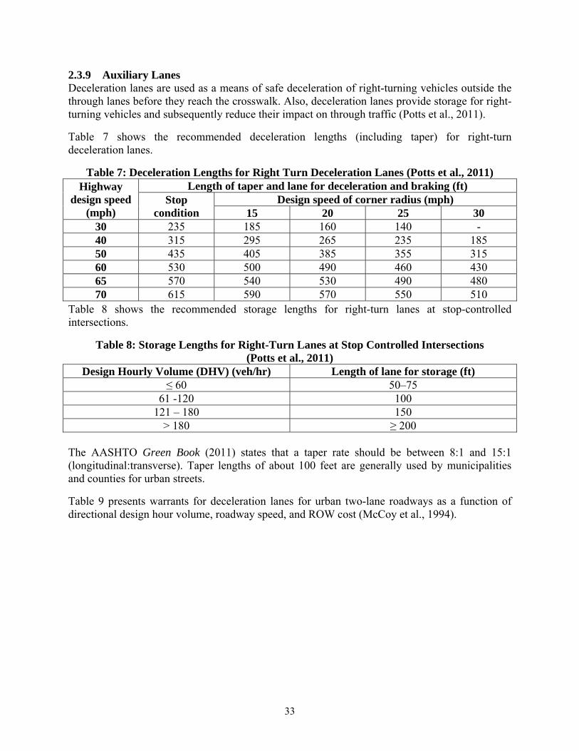
33
2.3.9 Auxiliary Lanes Deceleration lanes are used as a means of safe deceleration of right-turning vehicles outside the through lanes before they reach the crosswalk. Also, deceleration lanes provide storage for right-turning vehicles and subsequently reduce their impact on through traffic (Potts et al., 2011).
Table 7 shows the recommended deceleration lengths (including taper) for right-turn deceleration lanes.
Table 7: Deceleration Lengths for Right Turn Deceleration Lanes (Potts et al., 2011) Highway
design speed (mph)
Length of taper and lane for deceleration and braking (ft)Stop
condition Design speed of corner radius (mph)
15 20 25 30 30 235 185 160 140 - 40 315 295 265 235 185 50 435 405 385 355 315 60 530 500 490 460 430 65 570 540 530 490 480 70 615 590 570 550 510
Table 8 shows the recommended storage lengths for right-turn lanes at stop-controlled intersections.
Table 8: Storage Lengths for Right-Turn Lanes at Stop Controlled Intersections (Potts et al., 2011)
Design Hourly Volume (DHV) (veh/hr) Length of lane for storage (ft)≤ 60 50–75
61 -120 100 121 – 180 150
> 180 ≥ 200 The AASHTO Green Book (2011) states that a taper rate should be between 8:1 and 15:1 (longitudinal:transverse). Taper lengths of about 100 feet are generally used by municipalities and counties for urban streets.
Table 9 presents warrants for deceleration lanes for urban two-lane roadways as a function of directional design hour volume, roadway speed, and ROW cost (McCoy et al., 1994).
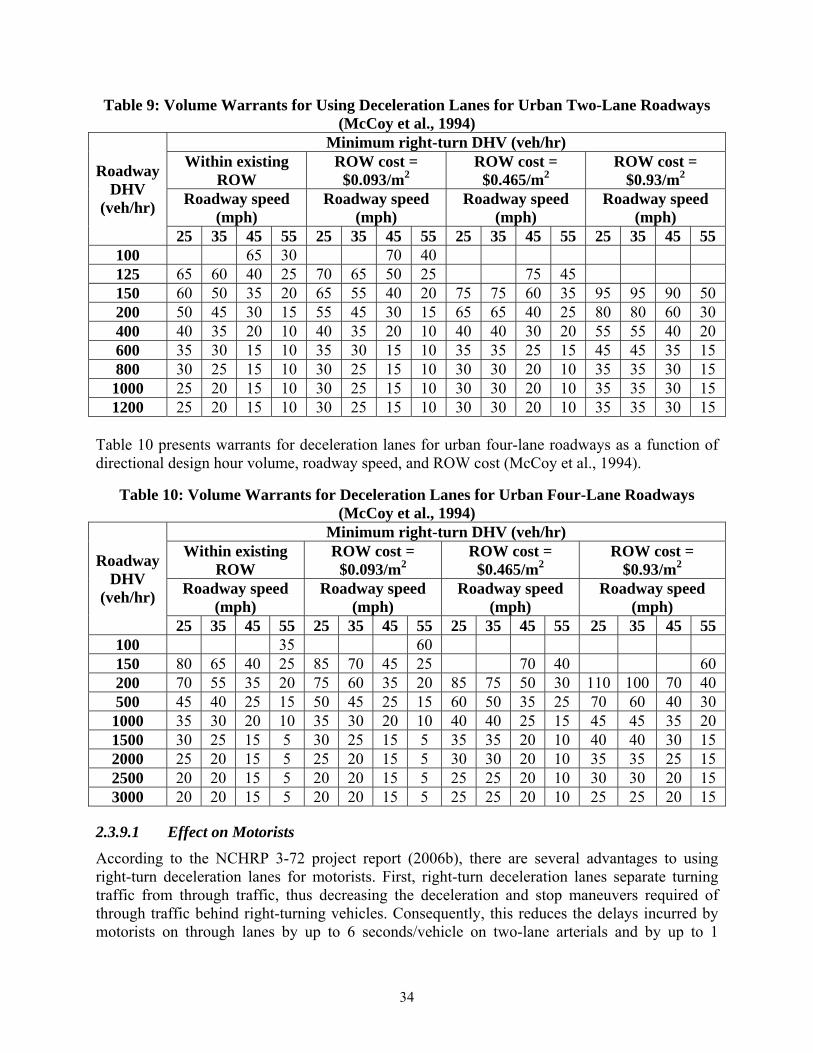
34
Table 9: Volume Warrants for Using Deceleration Lanes for Urban Two-Lane Roadways (McCoy et al., 1994)
Roadway DHV
(veh/hr)
Minimum right-turn DHV (veh/hr)Within existing
ROW ROW cost =
$0.093/m2 ROW cost =
$0.465/m2 ROW cost =
$0.93/m2 Roadway speed
(mph) Roadway speed
(mph) Roadway speed
(mph) Roadway speed
(mph) 25 35 45 55 25 35 45 55 25 35 45 55 25 35 45 55
100 65 30 70 40 125 65 60 40 25 70 65 50 25 75 45 150 60 50 35 20 65 55 40 20 75 75 60 35 95 95 90 50 200 50 45 30 15 55 45 30 15 65 65 40 25 80 80 60 30 400 40 35 20 10 40 35 20 10 40 40 30 20 55 55 40 20 600 35 30 15 10 35 30 15 10 35 35 25 15 45 45 35 15 800 30 25 15 10 30 25 15 10 30 30 20 10 35 35 30 15 1000 25 20 15 10 30 25 15 10 30 30 20 10 35 35 30 15 1200 25 20 15 10 30 25 15 10 30 30 20 10 35 35 30 15
Table 10 presents warrants for deceleration lanes for urban four-lane roadways as a function of directional design hour volume, roadway speed, and ROW cost (McCoy et al., 1994).
Table 10: Volume Warrants for Deceleration Lanes for Urban Four-Lane Roadways (McCoy et al., 1994)
Roadway DHV
(veh/hr)
Minimum right-turn DHV (veh/hr)Within existing
ROW ROW cost =
$0.093/m2 ROW cost =
$0.465/m2 ROW cost =
$0.93/m2 Roadway speed
(mph) Roadway speed
(mph) Roadway speed
(mph) Roadway speed
(mph) 25 35 45 55 25 35 45 55 25 35 45 55 25 35 45 55
100 35 60 150 80 65 40 25 85 70 45 25 70 40 60 200 70 55 35 20 75 60 35 20 85 75 50 30 110 100 70 40 500 45 40 25 15 50 45 25 15 60 50 35 25 70 60 40 30 1000 35 30 20 10 35 30 20 10 40 40 25 15 45 45 35 20 1500 30 25 15 5 30 25 15 5 35 35 20 10 40 40 30 15 2000 25 20 15 5 25 20 15 5 30 30 20 10 35 35 25 15 2500 20 20 15 5 20 20 15 5 25 25 20 10 30 30 20 15 3000 20 20 15 5 20 20 15 5 25 25 20 10 25 25 20 15
2.3.9.1 Effect on Motorists
According to the NCHRP 3-72 project report (2006b), there are several advantages to using right-turn deceleration lanes for motorists. First, right-turn deceleration lanes separate turning traffic from through traffic, thus decreasing the deceleration and stop maneuvers required of through traffic behind right-turning vehicles. Consequently, this reduces the delays incurred by motorists on through lanes by up to 6 seconds/vehicle on two-lane arterials and by up to 1
35
second/vehicle on four-lane arterials. Furthermore, safety is improved by reducing rear-end and sideswipe crashes. Second, deceleration lanes provide storage for turning vehicles without disrupting intersection operations. Accordingly, right-turn deceleration lanes increase intersection capacity. Additionally, due to a decrease in speed-change cycles, vehicle travel costs are reduced by reducing fuel consumption, which, in turn, leads to reduced emissions and improved air quality. However, the right-turn deceleration lane may be mistaken for a through lane. Hence, this can be considered a disadvantage (Potts et al., 2006b).
2.3.9.2 Effect on Pedestrians
Since right-turning vehicles are separated from through traffic, this allows them to slow down before negotiating the right-turn and yielding to pedestrians as they cross the lane. Moreover, right-turn deceleration lanes distinguish through traffic from right-turning traffic for pedestrians (Potts et al., 2006b).
However, this configuration increases the distance pedestrians have to cross. Furthermore, drivers attempting a right turn may be focused on crossing traffic rather than pedestrians. Moreover, separating right-turning movements from through movements allows for more right-turn-on-red maneuvers at signalized intersections, increasing the opportunity for conflict between pedestrians and motorists (Potts et al., 2006b).
2.3.9.3 Effect on Bicyclists
The use of proper markings and signage for bike lanes encourages bicyclists and motorists to cross paths before the intersection, separating this conflict point from others downstream. Also, forcing bicyclists and motorists to perform the weave ahead of the intersection allows for vehicles to pass bicyclists, due to the larger speed differential, rather than the motorist and bicyclist travelling alongside each other (Potts et al., 2006b).
However, the provision of right-turn deceleration lanes forces motorists to cross the bike path to perform the right-turn, which leads to more conflicts with bicyclists. Furthermore, the length of the deceleration lane has a significant impact on the level of exposure that bicyclists experience for this maneuver (Potts et al., 2006b).
2.4 TxDOT Design Guidance The TxDOT Roadway Design Manual (2013) has different clear zone requirements depending on area type, roadway functional class, design speed, and average daily traffic (ADT). Traffic signal supports are excluded from clear zone requirements due to their need to be located near the traveled way to provide adequate traffic control. However, these devices are recommended to be placed as far from the roadway as practical since they are typically not installed with breakaway supports. The Roadside Design Guide (AASHTO, 2011) recommends that the use breakaway supports be considered when signal pole assemblies and foundations are to be installed in close proximity to traffic lanes or within medians/islands. However, since a fallen traffic signal support and mast arm assembly can be a danger or obstruction, use of breakaway supports may not be desirable. No concrete base or foundation support for a traffic signal with a breakaway device should be more than 4 inches above the finished ground line to prevent snagging of a vehicle undercarriage per the Texas Manual on Uniform Traffic Control Devices (TMUTCD) (TxDOT, 2011).
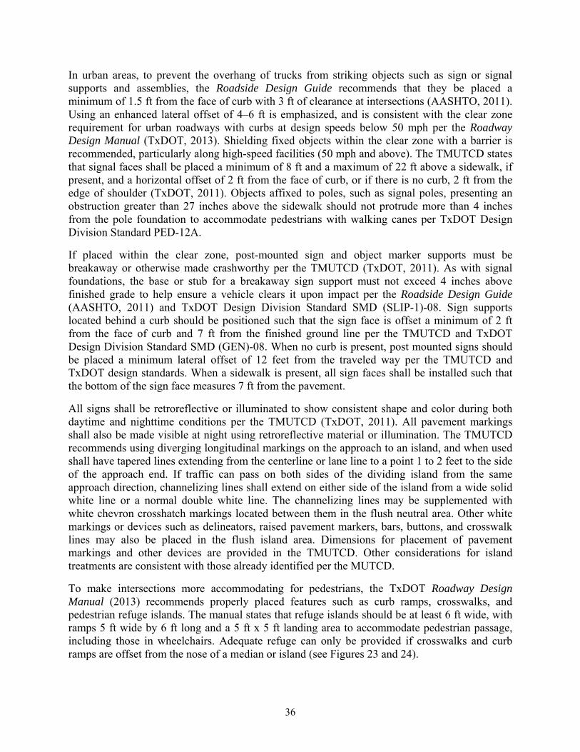
36
In urban areas, to prevent the overhang of trucks from striking objects such as sign or signal supports and assemblies, the Roadside Design Guide recommends that they be placed a minimum of 1.5 ft from the face of curb with 3 ft of clearance at intersections (AASHTO, 2011). Using an enhanced lateral offset of 4–6 ft is emphasized, and is consistent with the clear zone requirement for urban roadways with curbs at design speeds below 50 mph per the Roadway Design Manual (TxDOT, 2013). Shielding fixed objects within the clear zone with a barrier is recommended, particularly along high-speed facilities (50 mph and above). The TMUTCD states that signal faces shall be placed a minimum of 8 ft and a maximum of 22 ft above a sidewalk, if present, and a horizontal offset of 2 ft from the face of curb, or if there is no curb, 2 ft from the edge of shoulder (TxDOT, 2011). Objects affixed to poles, such as signal poles, presenting an obstruction greater than 27 inches above the sidewalk should not protrude more than 4 inches from the pole foundation to accommodate pedestrians with walking canes per TxDOT Design Division Standard PED-12A.
If placed within the clear zone, post-mounted sign and object marker supports must be breakaway or otherwise made crashworthy per the TMUTCD (TxDOT, 2011). As with signal foundations, the base or stub for a breakaway sign support must not exceed 4 inches above finished grade to help ensure a vehicle clears it upon impact per the Roadside Design Guide (AASHTO, 2011) and TxDOT Design Division Standard SMD (SLIP-1)-08. Sign supports located behind a curb should be positioned such that the sign face is offset a minimum of 2 ft from the face of curb and 7 ft from the finished ground line per the TMUTCD and TxDOT Design Division Standard SMD (GEN)-08. When no curb is present, post mounted signs should be placed a minimum lateral offset of 12 feet from the traveled way per the TMUTCD and TxDOT design standards. When a sidewalk is present, all sign faces shall be installed such that the bottom of the sign face measures 7 ft from the pavement.
All signs shall be retroreflective or illuminated to show consistent shape and color during both daytime and nighttime conditions per the TMUTCD (TxDOT, 2011). All pavement markings shall also be made visible at night using retroreflective material or illumination. The TMUTCD recommends using diverging longitudinal markings on the approach to an island, and when used shall have tapered lines extending from the centerline or lane line to a point 1 to 2 feet to the side of the approach end. If traffic can pass on both sides of the dividing island from the same approach direction, channelizing lines shall extend on either side of the island from a wide solid white line or a normal double white line. The channelizing lines may be supplemented with white chevron crosshatch markings located between them in the flush neutral area. Other white markings or devices such as delineators, raised pavement markers, bars, buttons, and crosswalk lines may also be placed in the flush island area. Dimensions for placement of pavement markings and other devices are provided in the TMUTCD. Other considerations for island treatments are consistent with those already identified per the MUTCD.
To make intersections more accommodating for pedestrians, the TxDOT Roadway Design Manual (2013) recommends properly placed features such as curb ramps, crosswalks, and pedestrian refuge islands. The manual states that refuge islands should be at least 6 ft wide, with ramps 5 ft wide by 6 ft long and a 5 ft x 5 ft landing area to accommodate pedestrian passage, including those in wheelchairs. Adequate refuge can only be provided if crosswalks and curb ramps are offset from the nose of a median or island (see Figures 23 and 24).
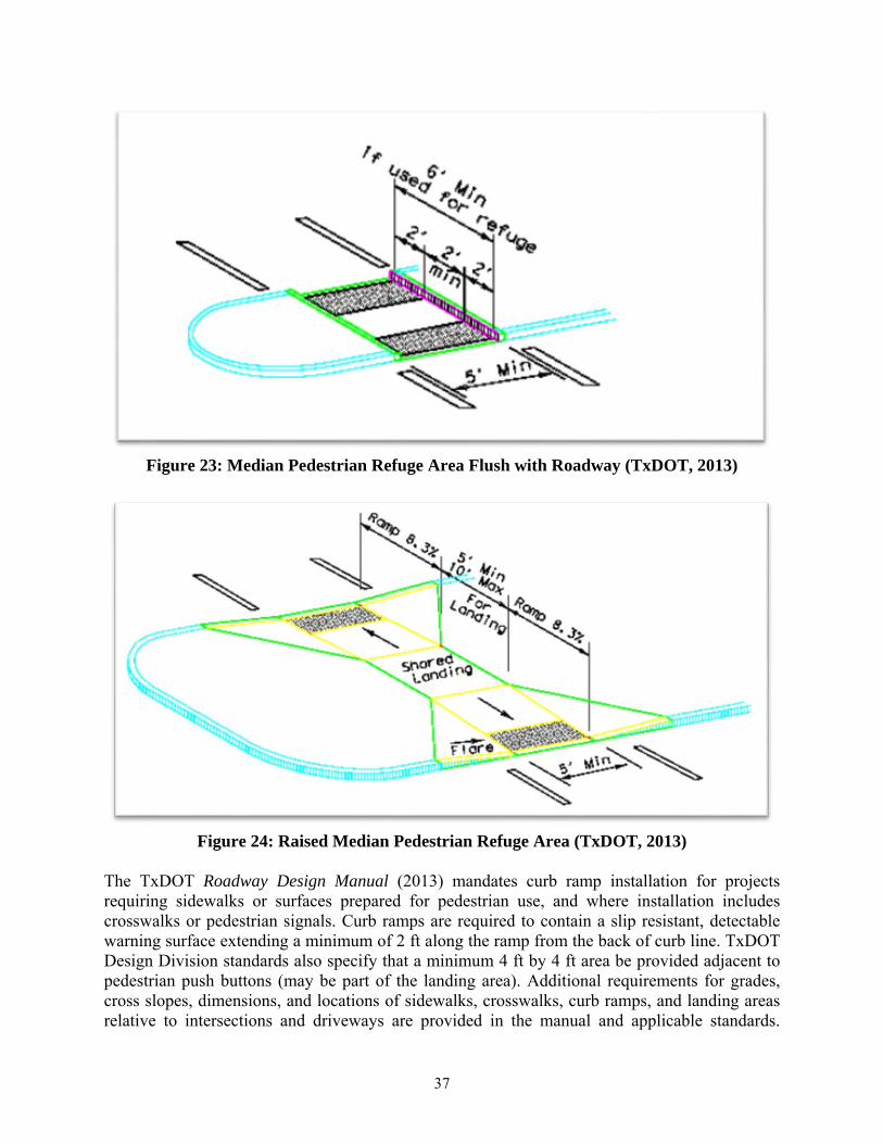
37
Figure 23: Median Pedestrian Refuge Area Flush with Roadway (TxDOT, 2013)
Figure 24: Raised Median Pedestrian Refuge Area (TxDOT, 2013)
The TxDOT Roadway Design Manual (2013) mandates curb ramp installation for projects requiring sidewalks or surfaces prepared for pedestrian use, and where installation includes crosswalks or pedestrian signals. Curb ramps are required to contain a slip resistant, detectable warning surface extending a minimum of 2 ft along the ramp from the back of curb line. TxDOT Design Division standards also specify that a minimum 4 ft by 4 ft area be provided adjacent to pedestrian push buttons (may be part of the landing area). Additional requirements for grades, cross slopes, dimensions, and locations of sidewalks, crosswalks, curb ramps, and landing areas relative to intersections and driveways are provided in the manual and applicable standards.
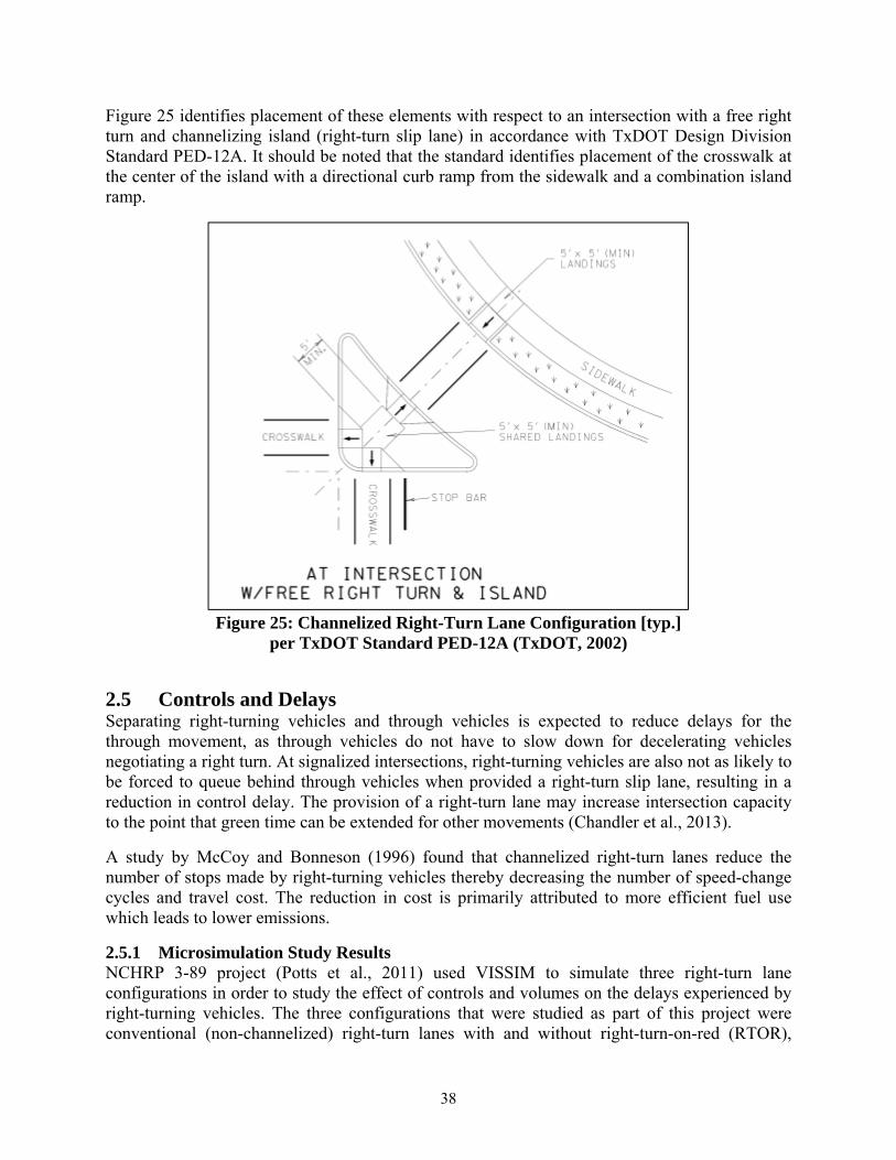
38
Figure 25 identifies placement of these elements with respect to an intersection with a free right turn and channelizing island (right-turn slip lane) in accordance with TxDOT Design Division Standard PED-12A. It should be noted that the standard identifies placement of the crosswalk at the center of the island with a directional curb ramp from the sidewalk and a combination island ramp.
Figure 25: Channelized Right-Turn Lane Configuration [typ.]
per TxDOT Standard PED-12A (TxDOT, 2002)
2.5 Controls and Delays Separating right-turning vehicles and through vehicles is expected to reduce delays for the through movement, as through vehicles do not have to slow down for decelerating vehicles negotiating a right turn. At signalized intersections, right-turning vehicles are also not as likely to be forced to queue behind through vehicles when provided a right-turn slip lane, resulting in a reduction in control delay. The provision of a right-turn lane may increase intersection capacity to the point that green time can be extended for other movements (Chandler et al., 2013).
A study by McCoy and Bonneson (1996) found that channelized right-turn lanes reduce the number of stops made by right-turning vehicles thereby decreasing the number of speed-change cycles and travel cost. The reduction in cost is primarily attributed to more efficient fuel use which leads to lower emissions.
2.5.1 Microsimulation Study Results NCHRP 3-89 project (Potts et al., 2011) used VISSIM to simulate three right-turn lane configurations in order to study the effect of controls and volumes on the delays experienced by right-turning vehicles. The three configurations that were studied as part of this project were conventional (non-channelized) right-turn lanes with and without right-turn-on-red (RTOR),
39
yield-controlled channelized right-turn lanes (15 mph, 50 ft radius), and signal-controlled channelized right-turn lanes (15 mph, 50 ft radius). The results of this study are summarized in this sub-section.
It was found that, for conventional right-turn lanes, delays incurred by right-turning vehicles are substantially impacted by through-traffic volumes. For through volumes of 1,600 veh/hour, delays experienced by RTOR vehicles are almost the same as those incurred by vehicles at an intersection that are not allowed to turn at the red light. For yield-controlled channelized right-turn lanes, delays are also impacted by through-traffic yet are less than those experienced on conventional right-turn lanes. Using yield-controlled channelized right-turn lanes was found to reduce delays, compared to conventional right-turn lanes (with RTOR), by 25 to 75 percent for right-turning vehicles.
The yield-controlled channelized right turn exhibited the lowest delays of the three studied configurations. The differences in delays were most pronounced at intersections with high through-traffic volumes. For high through-traffic volumes, the delays incurred by right-turning vehicles are typically the same for conventional right-turn lanes, signal-controlled right-turn slip lanes or yield-controlled right-turn slip lanes. For this condition, gaps are limited in the conflicting traffic stream, allowing few vehicles to merge while the approach receives a red signal indication. Therefore, the marginal benefit of using a right-turn slip lane (over using no RTOR conventional right-turn lanes) decreases as volume of through traffic increases. The greatest benefit of RTOR occurs when the conflicting through-traffic volume is low.
For yield-controlled channelized right-turn lanes, as the conflicting through volume increases, the impact of right-turn volume on delay also increases. For signal-controlled channelized right-turn lanes, delay is generally not impacted by through traffic. Signalization of the channelized right-turn lane provides traffic operational benefits only at high conflicting volumes on the cross street. At lower right-turn volumes, the traffic operational benefit of a channelized right-turn lane is relatively small as compared to the conventional right-turn lane.
Simulations of the three configurations showed that pedestrian volumes influence the delays experienced by right-turning traffic, with the largest delays incurred by vehicles turning at signal-controlled channelized right-turn lanes. For conventional right-turn lanes and yield-controlled channelized right-turn lanes, pedestrian crossings increased right-turn delays by 50 to 70 percent. It was also found that, for yield-controlled channelized right-turn lanes, the location of the crosswalk does not affect the delays incurred by right-turning vehicles.
The addition of an acceleration lane was found to reduce delays incurred by right-turning vehicles by 65 to 85 percent regardless of the volume of through traffic. Increasing the radius of the right turn, which consequently increases travel speed, reduced the delay by approximately 10 to 20 percent for each 5 mph increase in turning speed. Any reduction in delay may be diminished by the conflicting through-traffic volumes.
The green time for signalized channelized right-turn lanes can be extended by overlapping the right-turn signal phase with the cross street left-turn signal. However, this can be problematic since conflicting U-turns cannot be permitted from the cross-street left-turn lane. Additional green time is effective for reducing delays as the right-turning volume increases.
40
In the event that the crosswalk located within the right-turn slip lane is to have an accompanying pedestrian signal, an actuated signal can reduce vehicle delay. Caution should be exercised when using right-turn slip lanes where pedestrian crossing volumes exceed 1,000 pedestrians per day. This guidance is based on the 85th percentile pedestrian volume obtained from the Toronto intersection database used for the study’s safety evaluation.
2.6 European Regulations An FHWA-sponsored study was conducted in 1994 to examine pedestrian and bicyclist facilities and safety provisions in four European countries: England, Netherlands, Germany, and Switzerland (Zeeger, et al., 1994). The following sub-sections documents important findings from this study.
2.6.1 England
2.6.1.1 Pedestrian Facilities
Four types of pedestrian crossings were observed in England:
a. Zebra crossings:
Zebra crossings are located at midblock locations, never at intersections, with dashed lines along both sides of the crosswalk, which is designated with wide white stripes that run transverse to the pedestrian path. Longitudinal pavement markings along the vehicle approach exhibit a zigzag pattern in advance of the crosswalk to alert drivers to the impending crossing. These crossings are often accompanied by flashing yellow lights on each side of the crosswalk. Drivers are required to yield to pedestrians at these crossings.
b. Pelican crossings:
Pelican crossings are also located at midblock locations, and are accompanied by traffic signals with push-button actuated pedestrian phases. The pedestrian walk interval is designated using a green symbol and the do not cross indication is represented by a red symbol. While pelican crossings are also delineated with dashed lines and zigzag approach markings, they do not have transverse striping throughout the crosswalk.
c. Toucan crossings:
These crosswalks are typically shared between pedestrians and bicyclists with their own signal indications, and are bounded by white square markings. The minimum width for these crosswalks is 10 feet, with 13 feet being desirable. These crossings are preferably equipped with vehicle detection on all approaches, infrared lamp monitoring, push-button signals on all corners of the crossing, a tactile warning surface and audible beepers. The signal indications are green pedestrian figure, red figure, and green bicycle.
d. Puffin (Pedestrian User Friendly INtelligent) crossings:
These crosswalks are installed at intersections, equipped with pedestrian push-buttons and infrared or pressure mat detectors. These devices are used to detect the presence of pedestrians and subsequently call the walk interval. It also helps reduce vehicular delays by eliminating false calls. If a pedestrian is detected and the vehicle phase has completed, the pedestrian signal will display a green symbol indicating that the pedestrian(s) may cross. If pedestrians are detected on
41
the crosswalk when the walk interval is about to end, the walk time is extended to allow for slower pedestrians or pedestrians who have just started crossing to continue their path safely. Unlike the pelican crossing, the puffin crossing has pedestrian signal displays on the near side of the crosswalk with an orientation that encourages pedestrians to look toward approaching traffic while waiting for a walk indication. This type of crosswalk is the most recent innovation in pedestrian safety improvement and vehicular delay reduction. However, since the detectors cannot locate pedestrians outside the crosswalk boundaries, it may be necessary to install physical barriers on the sidewalk to channel pedestrians into the crossing path. For visually impaired pedestrians, tactile warning surfaces should be introduced to guide them into the crosswalk. This kind of crosswalk was implemented at 27 intersections in Great Britain at the time of the report. It is believed that, depending on their proven efficiency, they would replace pelican and other crossings in the future.
At some pedestrian crossings, pedestrians are advised to look in the direction of approaching traffic using messages such as “Look Right” or “Look Left.” These messages were common in London where tourist activity is high. Pedestrian refuge islands were found at many intersections and midblock crossings to reduce the crossing distance for pedestrians. They were typically equipped with curb ramps and a tactile warning surface for visually impaired pedestrians. At a few locations, pedestrian crossing was prohibited due to unsafe traffic conditions. These areas were designated using flashing message displays.
2.6.1.2 Bicycle Facilities
Bicycle lanes were found to be narrow in Great Britain with some not exceeding 3 ft wide. Some city streets implemented contraflow bike lanes, i.e., bikes going in the opposite direction of vehicular flow. The entrance and exit to bike facilities that are meant for non-motorized modes are typically protected to prevent vehicular encroachment. Bicyclists are also allowed to use other infrastructure, such as bus lanes and abandoned rail lines.
2.6.1.3 Traffic Calming Strategies
A number of traffic calming strategies are employed in Great Britain. These include zigzag routes, lane width reductions, roundabouts and speed humps. In particular, speed humps appeared to be effective at warning drivers of conditions requiring them to reduce speed.
Another traffic calming strategy observed in England is the use of speed cushions, which function like a speed hump except that they do not span the entire width of the roadway. Often made of rubber, these devices often slow passenger cars and small vans, but not transit buses due to their wider axles that can span a single cushion. This way, passengers onboard buses do not experience any discomfort as the bus crosses over a cushion. Therefore, this technique is effective at slowing passenger cars while not hindering the path of buses and emergency vehicles.
2.6.2 Netherlands
2.6.2.1 Pedestrian Facilities
Unlike England, for midblock crossing locations, the Netherlands uses “block” crosswalks. These are designated by only a dashed line across the roadway indicating that vehicles should
42
not be assumed to stop. Only at locations where vehicles can be expected to stop are zebra crossings employed.
Similar to England, the pedestrian signals use a green symbol of a person when pedestrians are permitted to cross and a red symbol when they are not. A flashing green symbol indicates that continuing to cross is still permissible, but that the don’t walk indication will appear soon and pedestrians should not begin crossing. High volumes of pedestrians and vehicles warrant the use of pedestrian signals at arterial intersections.
In the City of Delft, zebra crosswalks are commonly used. The signal indications there include a green man (walk), yellow triangle (continue but do not begin crossing) and red man (don’t walk).
2.6.2.2 Bicycle Facilities
Bicycle Lanes In the Netherlands, it is common practice to separate bicyclists from motorists whenever the speed exceeds 30 kph. Bike lanes there are wide enough to allow two bicyclists to ride side-by-side. These lanes are marked in red and feature white bicycle symbols. Bike lanes are typically located between the lanes designated for motor vehicles and the pedestrian walkway, sometimes even part of the sidewalk.
Bicycle Signals High volumes of motor vehicles and bicyclists warrant the use of bicycle signals at arterial intersections. Bike signal indications are red, amber, and green. These signals are located either next to the vehicle signal, in the same 8-inch diameter signal face, or lower (3 feet high) using a smaller signal face (3-inch diameter). There are no flashing indications for bicyclists. According to a local official, bicyclists typically do not comply with these signal indications.
Some cities in the Netherlands provide bicyclists a leading interval before right-turning traffic is allowed to proceed at signalized intersections. In the Netherlands, right turn on red is prohibited for motorists but allowed for bicyclists at some locations. Bike lanes are typically located to the left of parked cars to allow motorists to spot bicyclists before approaching an intersection. Bike lanes are typically discontinued at intersections and traffic mixing occurs upstream to emphasize that the right-of-way is being shared by motorists and bicyclists.
Separate Bicycle Streets Separate bicycle-only streets may be implemented in central business district areas. However, these facilities tend to be inefficient at locations with high pedestrian activity where bicyclists are forced to dismount and become pedestrians themselves. At locations where there is low vehicular volume, separate bicycle streets are unnecessary and bicyclists and motorists can share the roadway.
Some signalized intersections have red bicycle boxes placed downstream of the auto stop line. These zones indicate that bicycles may proceed through the intersection before vehicles, improving the visibility of bicyclists to motorists and reducing conflict. In the Netherlands, the transportation network is designed to give priority to pedestrians and bicyclists. White triangle pavement markings indicate that motorists are expected to yield to non-motorized road users.
43
2.6.3 Germany
2.6.3.1 Pedestrian Facilities
Zebra crosswalks are used at locations where pedestrian and vehicular hourly volumes exceed 50 and 350, respectively. Some of the signals used to guide pedestrians also have bicycle indications. These crosswalks are required to be illuminated.
Pedestrian signals use walking man and standing man symbols to indicate to pedestrians when they can and cannot cross. Push-button devices typically alert the pedestrian when the walk indication is imminent while the pedestrian waits for their right-of-way.
Pedestrian refuge islands are often installed without zebra markings, eliminating the need to designate the path. This option tends to be less expensive to maintain than zebra crosswalks. All refuge islands are recommended to be wheelchair-accessible.
2.6.3.2 Bicycle Facilities
On-street bicycle facilities are installed flush with the vehicle traveled way and are typically designated by red paint or red colored pavement. These facilities are generally less expensive than off-street facilities.
Off-street bicycle facilities are sometimes installed along the sidewalks to separate bicyclists from motorists and are also delineated by red paint or pavement (to contrast the sidewalk). In the event that a parking lane exists, this design creates space for passengers to open the car doors and exit the vehicle safely.
In the city of Munster, one-way bike paths are typically 5 ft wide with a 2 ft separation from the motorized path. Some lanes allow for buses and bicycles to share a lane. These lanes are recommended to be at least 15-feet wide to allow for a bus to safely overtake a bicyclist as needed. These facilities use both bus and bike markings. Bike lanes bounded by continuous solid markings are for bicyclists exclusively. If the lane line is dashed, other road users can access the facility in the absence of bicycles.
2.6.4 Switzerland
2.6.4.1 Pedestrian Facilities
At the time of the report, the city of Basel had begun replacing asphalt pavement with stone surfaces to indicate a shared right-of-way with pedestrians, inviting them to use the roadway facility. Some streets had been completely closed to traffic and converted into exclusive pedestrian and bicycle facilities. Crossings are typically striped with yellow zebra markings. City officials there believe yellow to be more effective than white markings at drawing the attention of motorists.
As in other countries, signal indications include symbols of a green man, flashing green man and red man. Some pedestrian push-buttons are accompanied by a ticking sound with variable speed to indicate where the signal is in its cycle. Pedestrian refuge islands were observed on wide streets to reduce pedestrian crossing distances.
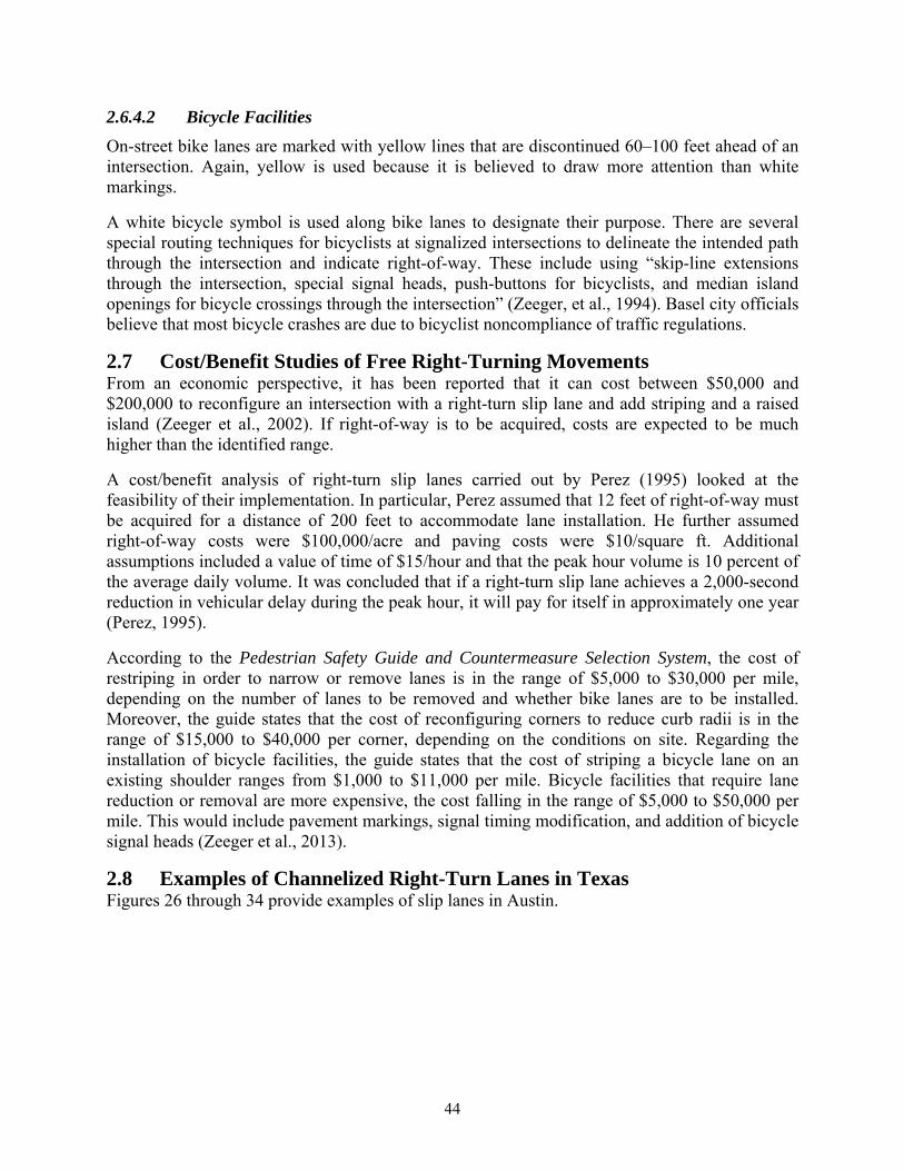
44
2.6.4.2 Bicycle Facilities
On-street bike lanes are marked with yellow lines that are discontinued 60–100 feet ahead of an intersection. Again, yellow is used because it is believed to draw more attention than white markings.
A white bicycle symbol is used along bike lanes to designate their purpose. There are several special routing techniques for bicyclists at signalized intersections to delineate the intended path through the intersection and indicate right-of-way. These include using “skip-line extensions through the intersection, special signal heads, push-buttons for bicyclists, and median island openings for bicycle crossings through the intersection” (Zeeger, et al., 1994). Basel city officials believe that most bicycle crashes are due to bicyclist noncompliance of traffic regulations.
2.7 Cost/Benefit Studies of Free Right-Turning Movements From an economic perspective, it has been reported that it can cost between $50,000 and $200,000 to reconfigure an intersection with a right-turn slip lane and add striping and a raised island (Zeeger et al., 2002). If right-of-way is to be acquired, costs are expected to be much higher than the identified range.
A cost/benefit analysis of right-turn slip lanes carried out by Perez (1995) looked at the feasibility of their implementation. In particular, Perez assumed that 12 feet of right-of-way must be acquired for a distance of 200 feet to accommodate lane installation. He further assumed right-of-way costs were $100,000/acre and paving costs were $10/square ft. Additional assumptions included a value of time of $15/hour and that the peak hour volume is 10 percent of the average daily volume. It was concluded that if a right-turn slip lane achieves a 2,000-second reduction in vehicular delay during the peak hour, it will pay for itself in approximately one year (Perez, 1995).
According to the Pedestrian Safety Guide and Countermeasure Selection System, the cost of restriping in order to narrow or remove lanes is in the range of $5,000 to $30,000 per mile, depending on the number of lanes to be removed and whether bike lanes are to be installed. Moreover, the guide states that the cost of reconfiguring corners to reduce curb radii is in the range of $15,000 to $40,000 per corner, depending on the conditions on site. Regarding the installation of bicycle facilities, the guide states that the cost of striping a bicycle lane on an existing shoulder ranges from $1,000 to $11,000 per mile. Bicycle facilities that require lane reduction or removal are more expensive, the cost falling in the range of $5,000 to $50,000 per mile. This would include pavement markings, signal timing modification, and addition of bicycle signal heads (Zeeger et al., 2013).
2.8 Examples of Channelized Right-Turn Lanes in Texas Figures 26 through 34 provide examples of slip lanes in Austin.
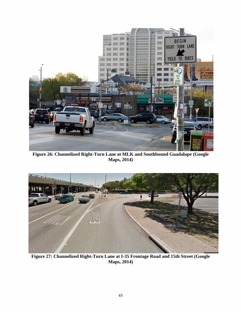
45
Figure 26: Channelized Right-Turn Lane at MLK and Southbound Guadalupe (Google
Maps, 2014)
Figure 27: Channelized Right-Turn Lane at I-35 Frontage Road and 15th Street (Google
Maps, 2014)
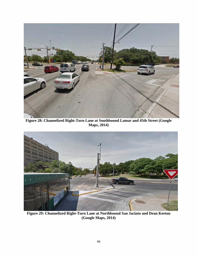
46
Figure 28: Channelized Right-Turn Lane at Southbound Lamar and 45th Street (Google
Maps, 2014)
Figure 29: Channelized Right-Turn Lane at Northbound San Jacinto and Dean Keeton
(Google Maps, 2014)
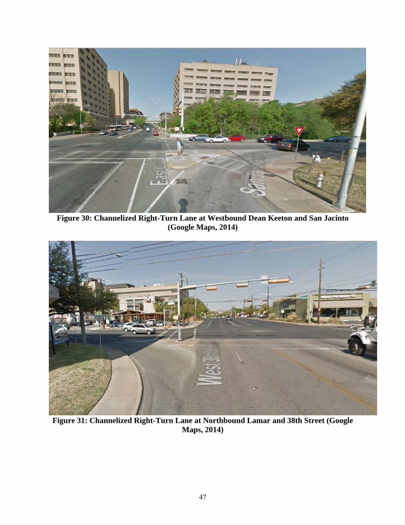
47
Figure 30: Channelized Right-Turn Lane at Westbound Dean Keeton and San Jacinto
(Google Maps, 2014)
Figure 31: Channelized Right-Turn Lane at Northbound Lamar and 38th Street (Google
Maps, 2014)
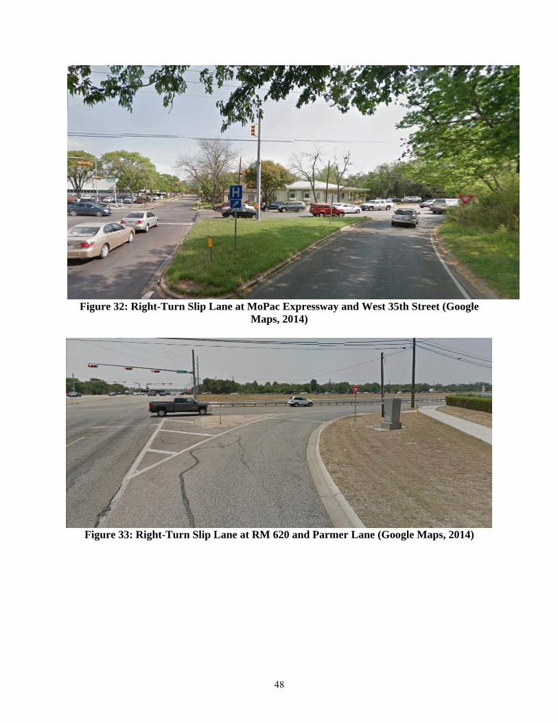
48
Figure 32: Right-Turn Slip Lane at MoPac Expressway and West 35th Street (Google
Maps, 2014)
Figure 33: Right-Turn Slip Lane at RM 620 and Parmer Lane (Google Maps, 2014)
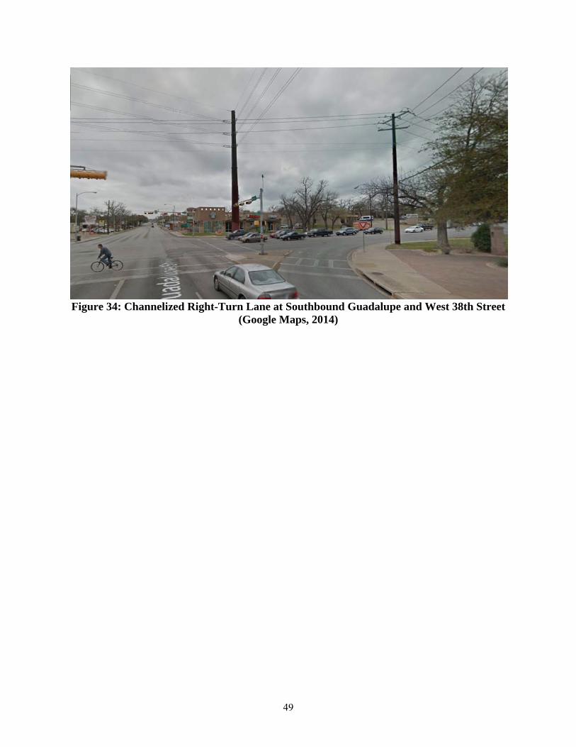
49
Figure 34: Channelized Right-Turn Lane at Southbound Guadalupe and West 38th Street
(Google Maps, 2014)

50
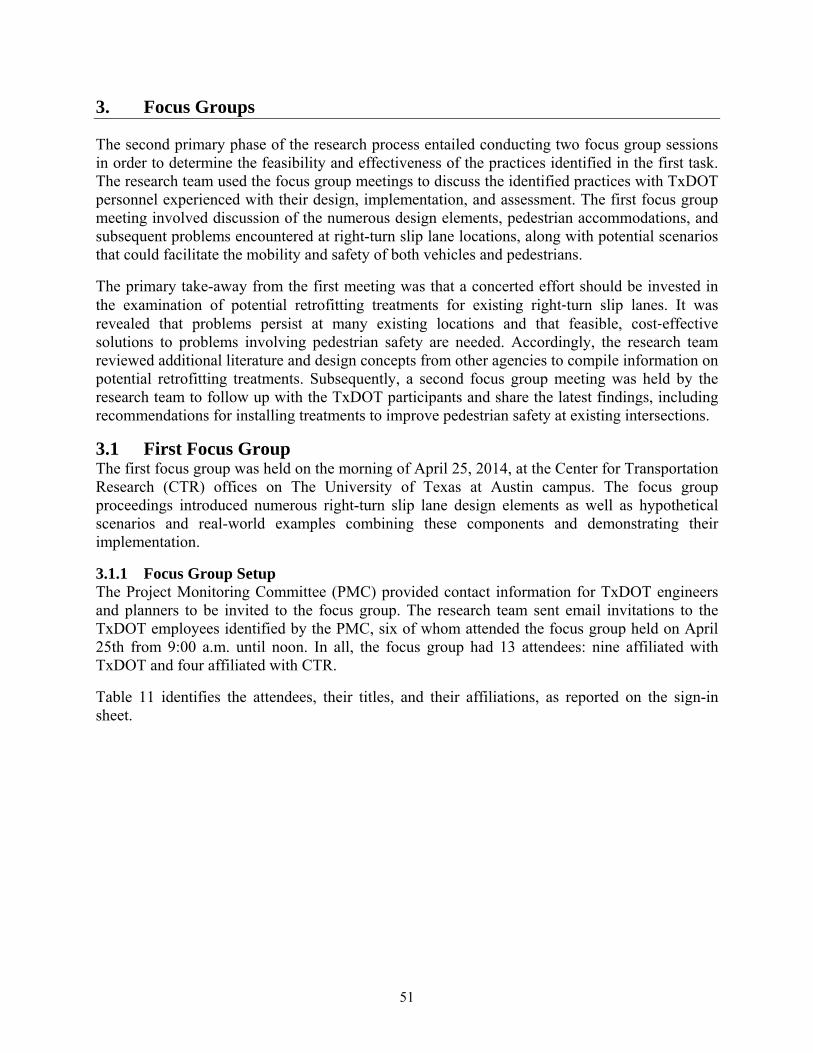
51
3. Focus Groups
The second primary phase of the research process entailed conducting two focus group sessions in order to determine the feasibility and effectiveness of the practices identified in the first task. The research team used the focus group meetings to discuss the identified practices with TxDOT personnel experienced with their design, implementation, and assessment. The first focus group meeting involved discussion of the numerous design elements, pedestrian accommodations, and subsequent problems encountered at right-turn slip lane locations, along with potential scenarios that could facilitate the mobility and safety of both vehicles and pedestrians.
The primary take-away from the first meeting was that a concerted effort should be invested in the examination of potential retrofitting treatments for existing right‐turn slip lanes. It was revealed that problems persist at many existing locations and that feasible, cost‐effective solutions to problems involving pedestrian safety are needed. Accordingly, the research team reviewed additional literature and design concepts from other agencies to compile information on potential retrofitting treatments. Subsequently, a second focus group meeting was held by the research team to follow up with the TxDOT participants and share the latest findings, including recommendations for installing treatments to improve pedestrian safety at existing intersections.
3.1 First Focus Group The first focus group was held on the morning of April 25, 2014, at the Center for Transportation Research (CTR) offices on The University of Texas at Austin campus. The focus group proceedings introduced numerous right-turn slip lane design elements as well as hypothetical scenarios and real-world examples combining these components and demonstrating their implementation.
3.1.1 Focus Group Setup The Project Monitoring Committee (PMC) provided contact information for TxDOT engineers and planners to be invited to the focus group. The research team sent email invitations to the TxDOT employees identified by the PMC, six of whom attended the focus group held on April 25th from 9:00 a.m. until noon. In all, the focus group had 13 attendees: nine affiliated with TxDOT and four affiliated with CTR.
Table 11 identifies the attendees, their titles, and their affiliations, as reported on the sign-in sheet.
52
Table 11: First Focus Group Attendees Attendee Title Affiliation Chandra Bhat Researcher CTR Scott Cunningham Lead Traffic Engineer TxDOT - PMCJennifer Duthie Research Supervisor CTR Chris Hehr Plan Development Section –
Design DivisionTxDOT - PMC
Brent Hillebrenner Transportation Engineer TxDOT Mason Gemar Researcher CTR Robert Guydosh TxDOT Darrin Jensen Project Manager TxDOT - PMC Pete Krause Landscape Architect TxDOT Adrian Martinez TxDOT Sonia Mercado Transportation Engineer TxDOT Leonard Polk Houston District Permit Section TxDOT Zeina Wafa Graduate Research Assistant CTR
3.1.2 Focus Group Proceedings The focus group content included a synopsis of the literature review, including relevant design guidelines and standards, carried out as part of the Task 1 requirements, along with input from TxDOT staff obtained at the project kick-off meeting. The primary topics covered at the focus group meeting were the following:
1. Design Elements
2. Hypothetical Scenarios
3. Right-Turn Slip Lanes in Texas
4. Preliminary Guidelines
3.1.2.1 Design Elements
The research team discussed a number of elements related to the design of a right-turn slip lane. These elements include radius of turn, angle of entry into the cross street, lane width, auxiliary lanes, crosswalk placement and orientation, type of traffic control, and methods to increase crosswalk compliance.
1. Radius of Turn and Angle of Entry
The radius of turn is important for both motorists and pedestrians as it affects the safety and comfort of the driver, as well as the safety conditions for pedestrians. Also, the radius of turn can influence vehicular mobility and delays. According to the AASHTO Green Book, the radius of turn is influenced by the angle of turn as well as the vehicle mix classification. At intersection locations with a high percentage of truck traffic, a larger radius is recommended in order to accommodate the larger vehicles and their turning paths. On the other hand, as the angle of turn increases, the recommended radius of turn decreases as shown in Table 12.
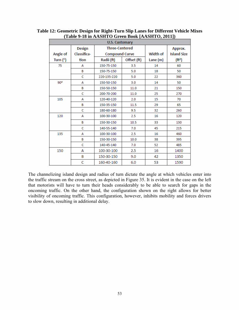
53
Table 12: Geometric Design for Right-Turn Slip Lanes for Different Vehicle Mixes (Table 9-18 in AASHTO Green Book [AASHTO, 2011])
The channelizing island design and radius of turn dictate the angle at which vehicles enter into the traffic stream on the cross street, as depicted in Figure 35. It is evident in the case on the left that motorists will have to turn their heads considerably to be able to search for gaps in the oncoming traffic. On the other hand, the configuration shown on the right allows for better visibility of oncoming traffic. This configuration, however, inhibits mobility and forces drivers to slow down, resulting in additional delay.
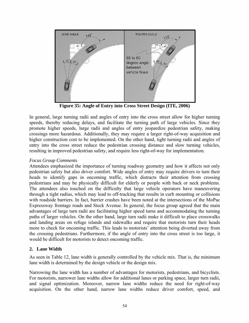
54
Figure 35: Angle of Entry into Cross Street Design (ITE, 2006)
In general, large turning radii and angles of entry into the cross street allow for higher turning speeds, thereby reducing delays, and facilitate the turning path of large vehicles. Since they promote higher speeds, large radii and angles of entry jeopardize pedestrian safety, making crossings more hazardous. Additionally, they may require a larger right-of-way acquisition and higher construction cost to be implemented. On the other hand, tight turning radii and angles of entry into the cross street reduce the pedestrian crossing distance and slow turning vehicles, resulting in improved pedestrian safety, and require less right-of-way for implementation.
Focus Group Comments Attendees emphasized the importance of turning roadway geometry and how it affects not only pedestrian safety but also driver comfort. Wide angles of entry may require drivers to turn their heads to identify gaps in oncoming traffic, which distracts their attention from crossing pedestrians and may be physically difficult for elderly or people with back or neck problems. The attendees also touched on the difficulty that large vehicle operators have maneuvering through a tight radius, which may lead to off-tracking that results in curb mounting or collisions with roadside barriers. In fact, barrier crashes have been noted at the intersections of the MoPac Expressway frontage roads and Steck Avenue. In general, the focus group agreed that the main advantages of large turn radii are facilitating higher speed turns and accommodating the turning paths of larger vehicles. On the other hand, large turn radii make it difficult to place crosswalks and landing areas on refuge islands and sidewalks and require that motorists turn their heads more to check for oncoming traffic. This leads to motorists’ attention being diverted away from the crossing pedestrians. Furthermore, if the angle of entry into the cross street is too large, it would be difficult for motorists to detect oncoming traffic.
2. Lane Width
As seen in Table 12, lane width is generally controlled by the vehicle mix. That is, the minimum lane width is determined by the design vehicle or the design mix.
Narrowing the lane width has a number of advantages for motorists, pedestrians, and bicyclists. For motorists, narrower lane widths allow for additional lanes or parking space, larger turn radii, and signal optimization. Moreover, narrow lane widths reduce the need for right-of-way acquisition. On the other hand, narrow lane widths reduce driver comfort, speed, and
55
maneuverability and increase delays. For pedestrians, reducing lane width reduces the crossing distance, calms traffic by decreasing speed, and provides additional space for medians, islands, or sidewalks. However, using the additional space to add a parking lane may reduce pedestrian visibility. For bicyclists, narrow lane widths calm traffic by reducing speed and provide additional space that can be used for bicycle facilities. Conversely, if the bicycle facility is originally a shared lane with motorists, a lane width reduction reduces the space available for both bicyclists and motorists and raises bicyclist safety issues. Also, reducing lane width limits the separation between bicyclists and motorists and endangers bicyclists, especially if the space for bicycles is not delineated.
Focus Group Comments The focus group participants highlighted the disadvantage of narrow lane widths in that there would be no room for a bike lane. Motorists and bicyclists would have to share the space, raising concerns about the safety of bicyclists. They also raised some issues concerning bicyclists using channelized right-turn lanes. First, bicyclists using a bike lane up to the cross street would be expected to cross the right-turn lane at the diverge area. Bicyclists are not likely to do so as the crossing distance is fairly long, leading to a heightened level of exposure. In fact, bicyclists are more likely to follow the right-turn slip lane even though they may not have enough space to maintain an acceptable level of safety. Bicyclists have to share the lane with turning vehicles as there is typically not a delineated bike lane through these turns, and are largely impacted by the speed at which vehicles are traveling. Issues with bicyclists negotiating right-turn slip lanes at RM 2244 and SH 360 and RM 2222 and SH 360 were noted.
3. Deceleration Lanes
The installation of deceleration lanes upstream of right-turn slip lanes has advantages and disadvantages for motorists, pedestrians, and bicyclists.
For motorists, the use of deceleration lanes separates through traffic from right-turning traffic, thereby decreasing delays, reducing rear-end and right-angle crashes, providing storage space for turning vehicles, improving mobility, and reducing emissions by decreasing the number of stop-and-go cycles for turning vehicles. On the other hand, deceleration lanes can be mistaken for through lanes, can be used to bypass queues at intersections leading to unsafe merging conditions downstream, may require right-of-way acquisition, and may increase side-swipe crashes due to lane changing.
For pedestrians, deceleration lanes may result in slower turning traffic and may help pedestrians identify turning vehicles from through vehicles. However, deceleration lanes increase a pedestrian’s crossing distance, so the net benefit to pedestrians is not necessarily positive. Deceleration lanes may also lead to driver distraction, and may increase pedestrian-motorist conflicts.
For bicyclists, deceleration lanes force through-traveling bicyclists and right-turning motorists to cross paths upstream of the intersection, creating a conflict. The deceleration lane lessens the speed differential between motorists and bicyclists, thereby allowing for safer passing. Moreover, the length of the deceleration lane has implications on the level of exposure of bicyclists, as the longer the deceleration lane, the longer the distance that bicyclists must travel between vehicle lanes and the more opportunity for lane changing to take place.
56
Focus Group Comments Focus group attendees stated that the main advantages of deceleration lanes are the provision of storage space and separation of turning traffic resulting in reduced rear-end crashes and delays at the intersection. The disadvantages of deceleration lanes include motorist confusion and bicyclist safety, especially at the upstream end of the right-turn slip lane. Motorists may confuse the deceleration lane with a through lane or use it to cheat queues leading to unsafe merging conditions downstream. This creates the need for proper signing. Participants also noted that sometimes designers opt for a taper prior to the right-turn slip lane instead of a full deceleration lane. This design was recently used in the New Braunfels area. Moreover, the attendees noted that the installation of a full deceleration lane is often contested by developers as they require larger capital costs (including right-of-way acquisition). If deceleration lanes are not installed initially, securing funds can be an issue for future installation. In Houston, there is less leeway for developers to choose not to install deceleration lanes. This may cause developers to opt out of the development. Attendees also noted that long deceleration lanes and high-speed turns are problematic (e.g., MoPac Expressway Frontage Road at Parmer Lane).
4. Crosswalk Placement and Orientation
There are six typical crosswalk configurations at right-turn slip lanes. These are described below and portrayed in Figure 36.
a. Crosswalks placed at the upstream end of the right-turn slip lane parallel to the sidewalk allow for good pedestrian visibility, as pedestrians are detected before the turn is made, provide a direct path for pedestrians along the approach sidewalk, and allow for adequate storage space. On the other hand, this configuration provides an indirect path for pedestrians on the cross street and may create conflict with motorists as pedestrians cross adjacent to the approach traffic.
b. Crosswalks placed at the upstream end of the right-turn slip lane perpendicular to the sidewalk allow for reduced pedestrian crossing distance (width of right-turn lane), provide good pedestrian visibility, and allow for adequate storage space. On the other hand, this placement and orientation provides an indirect path for pedestrians and may create conflict with motorists as pedestrians cross in close proximity to street traffic.
c. Crosswalks placed at the middle of the right-turn slip lane perpendicular to the sidewalk do not require multiple motorist decisions (drivers are not distracted by traffic), separate pedestrian crossing from adjacent through traffic, and allow for adequate storage space. On the other hand, this configuration provides an indirect path for both pedestrians on the approach street and pedestrians on the cross street.
d. Crosswalks placed at the downstream end of the right-turn slip lane parallel to the sidewalk provide a direct path for pedestrians along the cross street as well as provide for storage space for vehicles waiting to merge onto the cross street. On the other hand, this configuration increases the pedestrian crossing distance, provides an indirect path for pedestrians on the approach street, forces motorists to make multiple decisions at once (looking out for pedestrians as well as searching for gaps in oncoming traffic), and forces pedestrian crossing adjacent to street traffic.
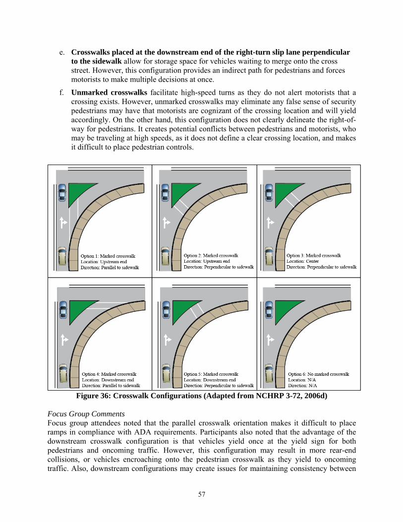
57
e. Crosswalks placed at the downstream end of the right-turn slip lane perpendicular to the sidewalk allow for storage space for vehicles waiting to merge onto the cross street. However, this configuration provides an indirect path for pedestrians and forces motorists to make multiple decisions at once.
f. Unmarked crosswalks facilitate high-speed turns as they do not alert motorists that a crossing exists. However, unmarked crosswalks may eliminate any false sense of security pedestrians may have that motorists are cognizant of the crossing location and will yield accordingly. On the other hand, this configuration does not clearly delineate the right-of-way for pedestrians. It creates potential conflicts between pedestrians and motorists, who may be traveling at high speeds, as it does not define a clear crossing location, and makes it difficult to place pedestrian controls.
Figure 36: Crosswalk Configurations (Adapted from NCHRP 3-72, 2006d)
Focus Group Comments Focus group attendees noted that the parallel crosswalk orientation makes it difficult to place ramps in compliance with ADA requirements. Participants also noted that the advantage of the downstream crosswalk configuration is that vehicles yield once at the yield sign for both pedestrians and oncoming traffic. However, this configuration may result in more rear-end collisions, or vehicles encroaching onto the pedestrian crosswalk as they yield to oncoming traffic. Also, downstream configurations may create issues for maintaining consistency between
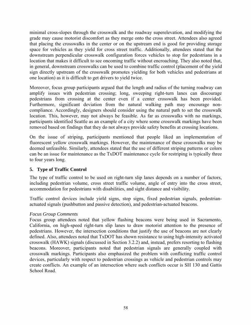
58
minimal cross-slopes through the crosswalk and the roadway superelevation, and modifying the grade may cause motorist discomfort as they merge onto the cross street. Attendees also agreed that placing the crosswalks in the center or on the upstream end is good for providing storage space for vehicles as they yield for cross street traffic. Additionally, attendees stated that the downstream perpendicular crosswalk configuration forces vehicles to stop for pedestrians in a location that makes it difficult to see oncoming traffic without encroaching. They also noted that, in general, downstream crosswalks can be used to combine traffic control (placement of the yield sign directly upstream of the crosswalk promotes yielding for both vehicles and pedestrians at one location) as it is difficult to get drivers to yield twice.
Moreover, focus group participants argued that the length and radius of the turning roadway can amplify issues with pedestrian crossing; long, sweeping right-turn lanes can discourage pedestrians from crossing at the center even if a center crosswalk has been provided. Furthermore, significant deviation from the natural walking path may encourage non-compliance. Accordingly, designers should consider using the natural path to set the crosswalk location. This, however, may not always be feasible. As far as crosswalks with no markings, participants identified Seattle as an example of a city where some crosswalk markings have been removed based on findings that they do not always provide safety benefits at crossing locations.
On the issue of striping, participants mentioned that people liked an implementation of fluorescent yellow crosswalk markings. However, the maintenance of these crosswalks may be deemed unfeasible. Similarly, attendees stated that the use of different striping patterns or colors can be an issue for maintenance as the TxDOT maintenance cycle for restriping is typically three to four years long.
5. Type of Traffic Control
The type of traffic control to be used on right-turn slip lanes depends on a number of factors, including pedestrian volume, cross street traffic volume, angle of entry into the cross street, accommodation for pedestrians with disabilities, and sight distance and visibility.
Traffic control devices include yield signs, stop signs, fixed pedestrian signals, pedestrian-actuated signals (pushbutton and passive detection), and pedestrian-actuated beacons.
Focus Group Comments Focus group attendees noted that yellow flashing beacons were being used in Sacramento, California, on high-speed right-turn slip lanes to draw motorist attention to the presence of pedestrians. However, the intersection conditions that justify the use of beacons are not clearly defined. Also, attendees noted that TxDOT has shown resistance to using high-intensity activated crosswalk (HAWK) signals (discussed in Section 3.2.2) and, instead, prefers resorting to flashing beacons. Moreover, participants noted that pedestrian signals are generally coupled with crosswalk markings. Participants also emphasized the problem with conflicting traffic control devices, particularly with respect to pedestrian crossings as vehicle and pedestrian controls may create conflicts. An example of an intersection where such conflicts occur is SH 130 and Gattis School Road.
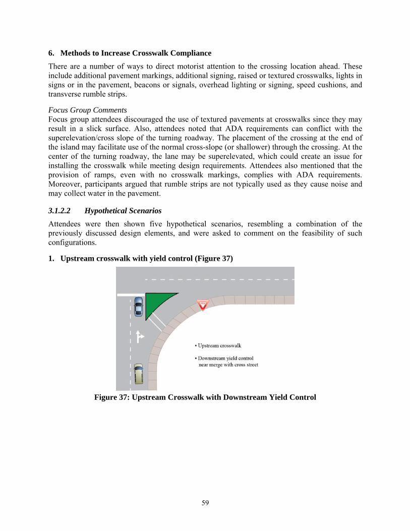
59
6. Methods to Increase Crosswalk Compliance
There are a number of ways to direct motorist attention to the crossing location ahead. These include additional pavement markings, additional signing, raised or textured crosswalks, lights in signs or in the pavement, beacons or signals, overhead lighting or signing, speed cushions, and transverse rumble strips.
Focus Group Comments Focus group attendees discouraged the use of textured pavements at crosswalks since they may result in a slick surface. Also, attendees noted that ADA requirements can conflict with the superelevation/cross slope of the turning roadway. The placement of the crossing at the end of the island may facilitate use of the normal cross-slope (or shallower) through the crossing. At the center of the turning roadway, the lane may be superelevated, which could create an issue for installing the crosswalk while meeting design requirements. Attendees also mentioned that the provision of ramps, even with no crosswalk markings, complies with ADA requirements. Moreover, participants argued that rumble strips are not typically used as they cause noise and may collect water in the pavement.
3.1.2.2 Hypothetical Scenarios
Attendees were then shown five hypothetical scenarios, resembling a combination of the previously discussed design elements, and were asked to comment on the feasibility of such configurations.
1. Upstream crosswalk with yield control (Figure 37)
Figure 37: Upstream Crosswalk with Downstream Yield Control
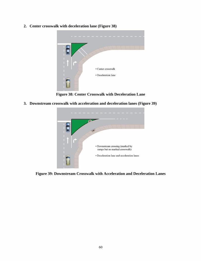
60
2. Center crosswalk with deceleration lane (Figure 38)
Figure 38: Center Crosswalk with Deceleration Lane
3. Downstream crosswalk with acceleration and deceleration lanes (Figure 39)
Figure 39: Downstream Crosswalk with Acceleration and Deceleration Lanes
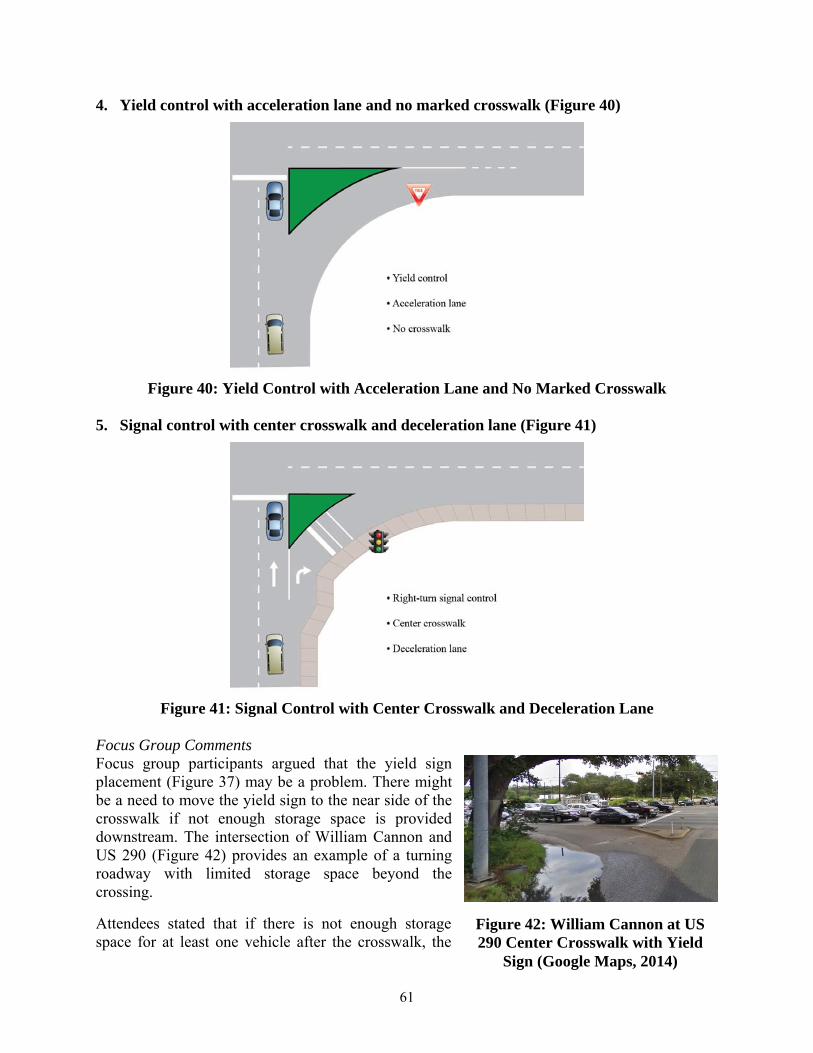
61
4. Yield control with acceleration lane and no marked crosswalk (Figure 40)
Figure 40: Yield Control with Acceleration Lane and No Marked Crosswalk 5. Signal control with center crosswalk and deceleration lane (Figure 41)
Figure 41: Signal Control with Center Crosswalk and Deceleration Lane Focus Group Comments Focus group participants argued that the yield sign placement (Figure 37) may be a problem. There might be a need to move the yield sign to the near side of the crosswalk if not enough storage space is provided downstream. The intersection of William Cannon and US 290 (Figure 42) provides an example of a turning roadway with limited storage space beyond the crossing.
Attendees stated that if there is not enough storage space for at least one vehicle after the crosswalk, the
Figure 42: William Cannon at US 290 Center Crosswalk with Yield
Sign (Google Maps, 2014)
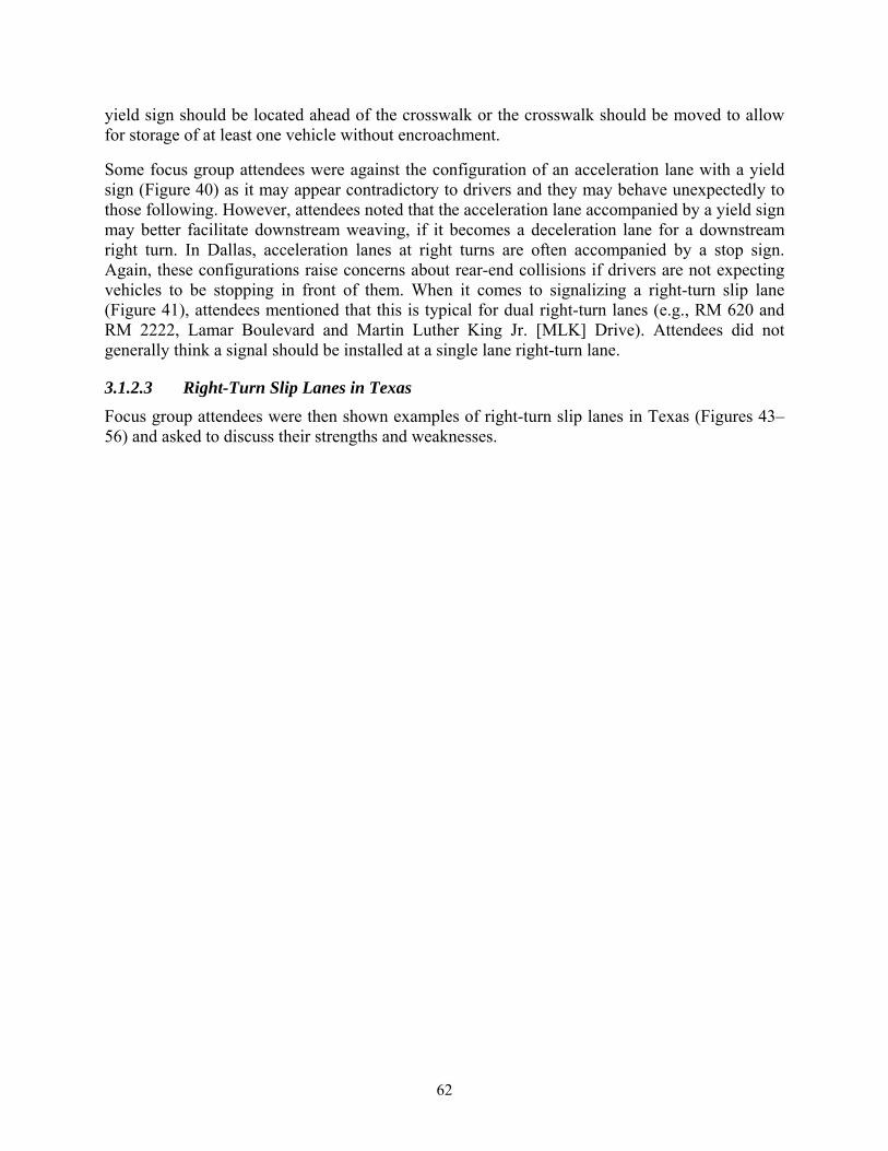
62
yield sign should be located ahead of the crosswalk or the crosswalk should be moved to allow for storage of at least one vehicle without encroachment.
Some focus group attendees were against the configuration of an acceleration lane with a yield sign (Figure 40) as it may appear contradictory to drivers and they may behave unexpectedly to those following. However, attendees noted that the acceleration lane accompanied by a yield sign may better facilitate downstream weaving, if it becomes a deceleration lane for a downstream right turn. In Dallas, acceleration lanes at right turns are often accompanied by a stop sign. Again, these configurations raise concerns about rear-end collisions if drivers are not expecting vehicles to be stopping in front of them. When it comes to signalizing a right-turn slip lane (Figure 41), attendees mentioned that this is typical for dual right-turn lanes (e.g., RM 620 and RM 2222, Lamar Boulevard and Martin Luther King Jr. [MLK] Drive). Attendees did not generally think a signal should be installed at a single lane right-turn lane.
3.1.2.3 Right-Turn Slip Lanes in Texas
Focus group attendees were then shown examples of right-turn slip lanes in Texas (Figures 43–56) and asked to discuss their strengths and weaknesses.
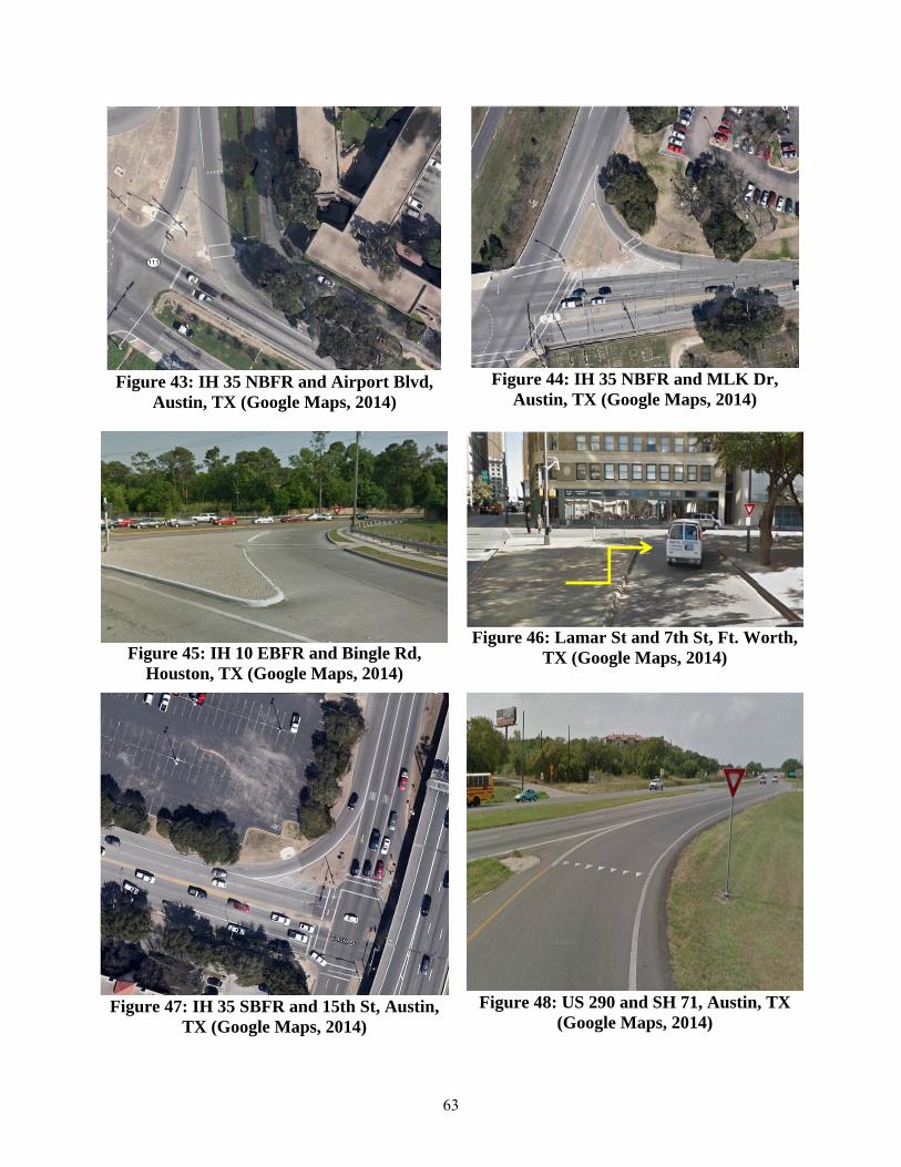
63
Figure 43: IH 35 NBFR and Airport Blvd,
Austin, TX (Google Maps, 2014)
Figure 44: IH 35 NBFR and MLK Dr,
Austin, TX (Google Maps, 2014)
Figure 45: IH 10 EBFR and Bingle Rd,
Houston, TX (Google Maps, 2014)
Figure 46: Lamar St and 7th St, Ft. Worth,
TX (Google Maps, 2014)
Figure 47: IH 35 SBFR and 15th St, Austin, TX (Google Maps, 2014)
Figure 48: US 290 and SH 71, Austin, TX (Google Maps, 2014)
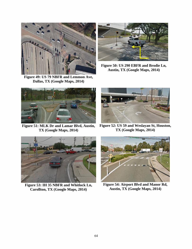
64
Figure 49: US 79 NBFR and Lemmon Ave,
Dallas, TX (Google Maps, 2014)
Figure 51: MLK Dr and Lamar Blvd, Austin,
TX (Google Maps, 2014)
Figure 52: US 59 and Weslayan St, Houston,
TX (Google Maps, 2014)
Figure 53: IH 35 NBFR and Whitlock Ln, Carollton, TX (Google Maps, 2014)
Figure 54: Airport Blvd and Manor Rd,
Austin, TX (Google Maps, 2014)
Figure 50: US 290 EBFR and Brodie Ln, Austin, TX (Google Maps, 2014)
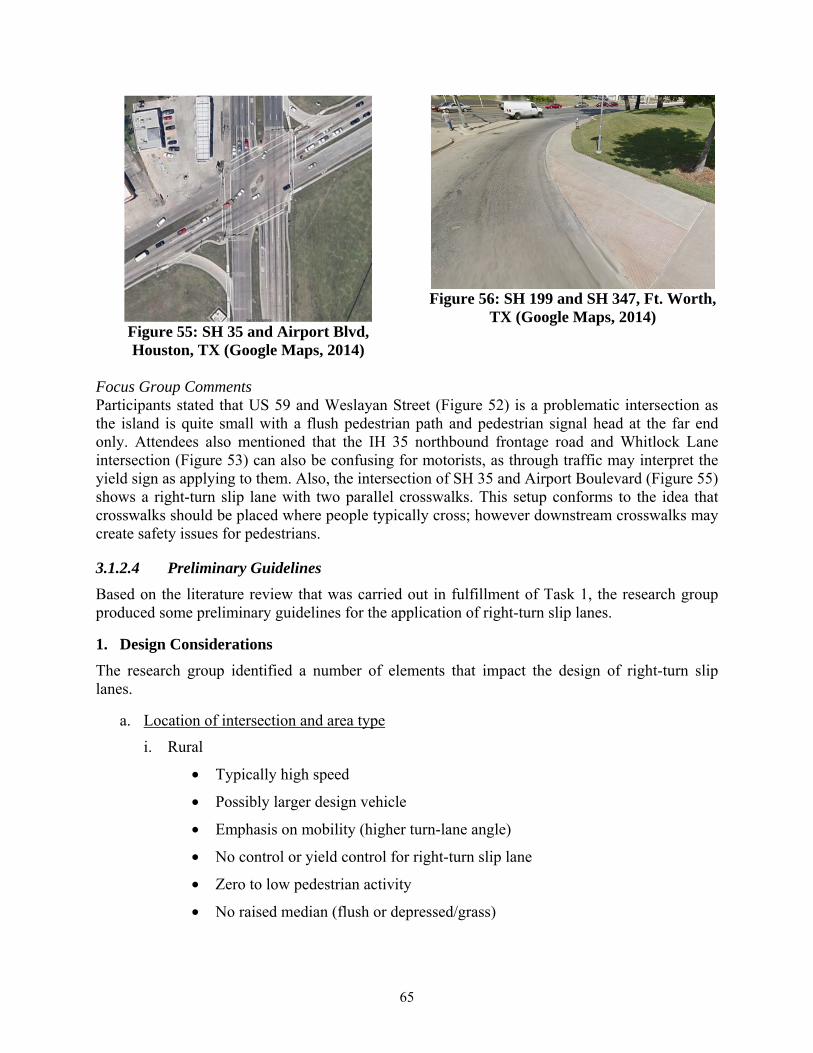
65
Figure 55: SH 35 and Airport Blvd, Houston, TX (Google Maps, 2014)
Figure 56: SH 199 and SH 347, Ft. Worth,
TX (Google Maps, 2014)
Focus Group Comments Participants stated that US 59 and Weslayan Street (Figure 52) is a problematic intersection as the island is quite small with a flush pedestrian path and pedestrian signal head at the far end only. Attendees also mentioned that the IH 35 northbound frontage road and Whitlock Lane intersection (Figure 53) can also be confusing for motorists, as through traffic may interpret the yield sign as applying to them. Also, the intersection of SH 35 and Airport Boulevard (Figure 55) shows a right-turn slip lane with two parallel crosswalks. This setup conforms to the idea that crosswalks should be placed where people typically cross; however downstream crosswalks may create safety issues for pedestrians.
3.1.2.4 Preliminary Guidelines
Based on the literature review that was carried out in fulfillment of Task 1, the research group produced some preliminary guidelines for the application of right-turn slip lanes.
1. Design Considerations
The research group identified a number of elements that impact the design of right-turn slip lanes.
a. Location of intersection and area type
i. Rural
• Typically high speed
• Possibly larger design vehicle
• Emphasis on mobility (higher turn-lane angle)
• No control or yield control for right-turn slip lane
• Zero to low pedestrian activity
• No raised median (flush or depressed/grass)
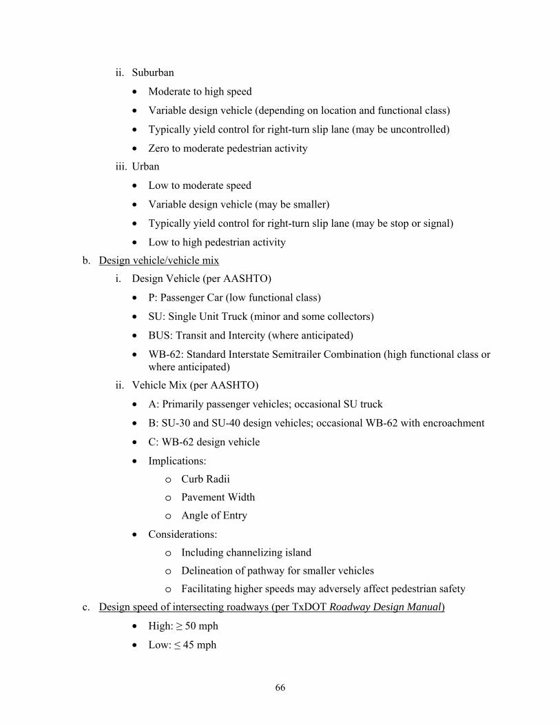
66
ii. Suburban
• Moderate to high speed
• Variable design vehicle (depending on location and functional class)
• Typically yield control for right-turn slip lane (may be uncontrolled)
• Zero to moderate pedestrian activity
iii. Urban
• Low to moderate speed
• Variable design vehicle (may be smaller)
• Typically yield control for right-turn slip lane (may be stop or signal)
• Low to high pedestrian activity
b. Design vehicle/vehicle mix
i. Design Vehicle (per AASHTO)
• P: Passenger Car (low functional class)
• SU: Single Unit Truck (minor and some collectors)
• BUS: Transit and Intercity (where anticipated)
• WB-62: Standard Interstate Semitrailer Combination (high functional class or where anticipated)
ii. Vehicle Mix (per AASHTO)
• A: Primarily passenger vehicles; occasional SU truck
• B: SU-30 and SU-40 design vehicles; occasional WB-62 with encroachment
• C: WB-62 design vehicle
• Implications:
o Curb Radii
o Pavement Width
o Angle of Entry
• Considerations:
o Including channelizing island
o Delineation of pathway for smaller vehicles
o Facilitating higher speeds may adversely affect pedestrian safety
c. Design speed of intersecting roadways (per TxDOT Roadway Design Manual)
• High: ≥ 50 mph
• Low: ≤ 45 mph
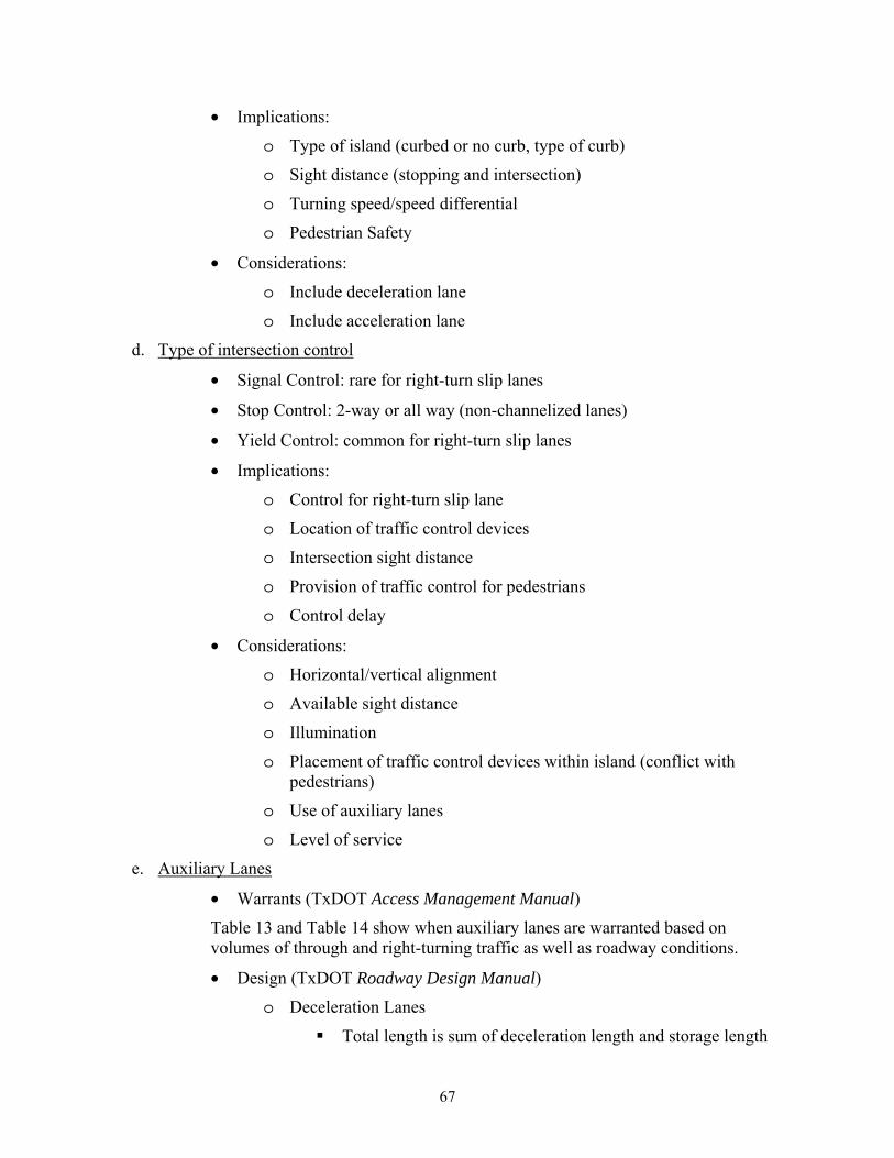
67
• Implications:
o Type of island (curbed or no curb, type of curb)
o Sight distance (stopping and intersection)
o Turning speed/speed differential
o Pedestrian Safety
• Considerations:
o Include deceleration lane
o Include acceleration lane
d. Type of intersection control
• Signal Control: rare for right-turn slip lanes
• Stop Control: 2-way or all way (non-channelized lanes)
• Yield Control: common for right-turn slip lanes
• Implications:
o Control for right-turn slip lane
o Location of traffic control devices
o Intersection sight distance
o Provision of traffic control for pedestrians
o Control delay
• Considerations:
o Horizontal/vertical alignment
o Available sight distance
o Illumination
o Placement of traffic control devices within island (conflict with pedestrians)
o Use of auxiliary lanes
o Level of service
e. Auxiliary Lanes
• Warrants (TxDOT Access Management Manual)
Table 13 and Table 14 show when auxiliary lanes are warranted based on volumes of through and right-turning traffic as well as roadway conditions.
• Design (TxDOT Roadway Design Manual)
o Deceleration Lanes
Total length is sum of deceleration length and storage length
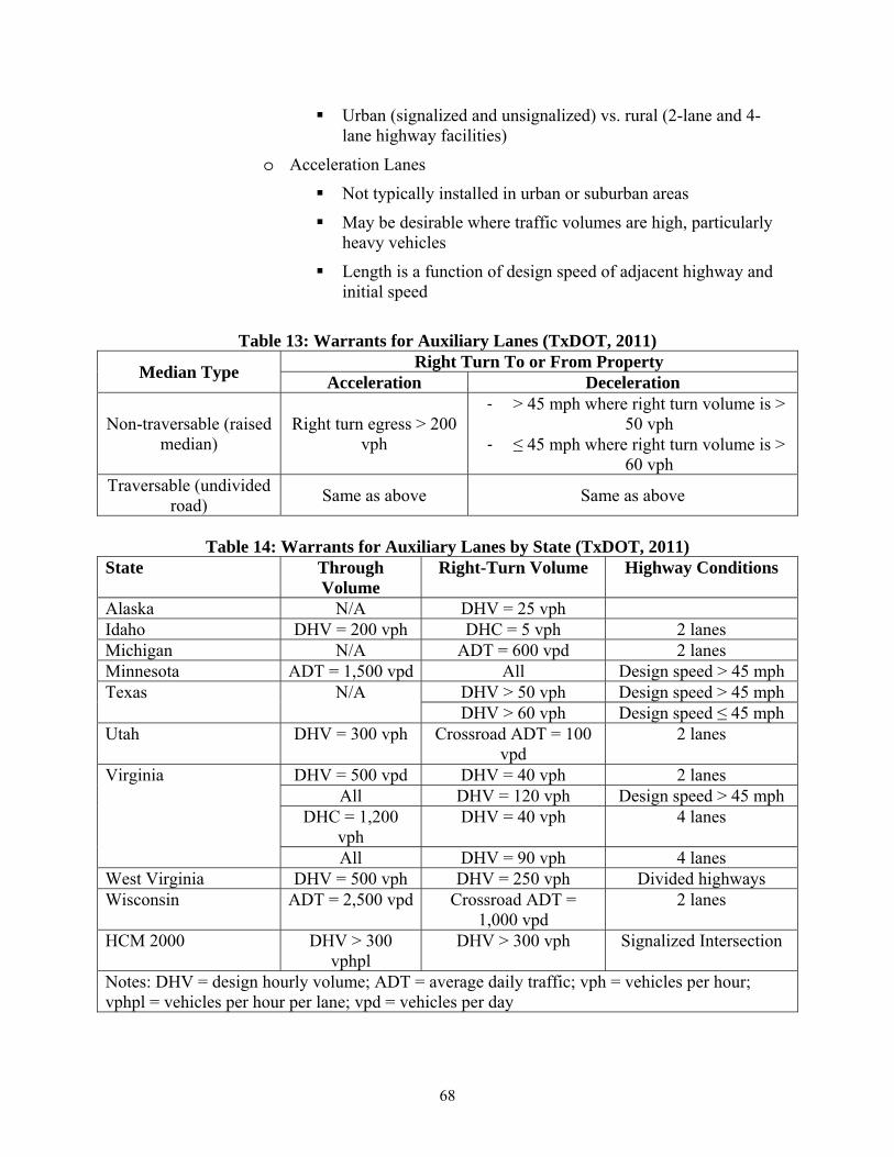
68
Urban (signalized and unsignalized) vs. rural (2-lane and 4-lane highway facilities)
o Acceleration Lanes
Not typically installed in urban or suburban areas
May be desirable where traffic volumes are high, particularly heavy vehicles
Length is a function of design speed of adjacent highway and initial speed
Table 13: Warrants for Auxiliary Lanes (TxDOT, 2011)
Median Type Right Turn To or From Property
Acceleration Deceleration
Non-traversable (raised median)
Right turn egress > 200 vph
‐ > 45 mph where right turn volume is > 50 vph ‐ ≤ 45 mph where right turn volume is > 60 vph
Traversable (undivided road)
Same as above Same as above
Table 14: Warrants for Auxiliary Lanes by State (TxDOT, 2011)
State Through Volume
Right-Turn Volume Highway Conditions
Alaska N/A DHV = 25 vph Idaho DHV = 200 vph DHC = 5 vph 2 lanes Michigan N/A ADT = 600 vpd 2 lanes Minnesota ADT = 1,500 vpd All Design speed > 45 mph Texas N/A DHV > 50 vph Design speed > 45 mph
DHV > 60 vph Design speed ≤ 45 mph Utah DHV = 300 vph Crossroad ADT = 100
vpd 2 lanes
Virginia DHV = 500 vpd DHV = 40 vph 2 lanes All DHV = 120 vph Design speed > 45 mph
DHC = 1,200 vph
DHV = 40 vph 4 lanes
All DHV = 90 vph 4 lanes West Virginia DHV = 500 vph DHV = 250 vph Divided highways Wisconsin ADT = 2,500 vpd Crossroad ADT =
1,000 vpd 2 lanes
HCM 2000 DHV > 300 vphpl
DHV > 300 vph Signalized Intersection
Notes: DHV = design hourly volume; ADT = average daily traffic; vph = vehicles per hour; vphpl = vehicles per hour per lane; vpd = vehicles per day
69
f. Number of crossing pedestrians/pedestrian activity
• High: Peak hour pedestrian volume ≥ 20 ped/h (design speed ≤ 35 mph) or ≥ 14 ped/h (design speed > 35 mph) (NCHRP Report 562)
• Low: < 20 ped/h
• Additional per City of Boulder, CO, Transportation Division
o Minimum Pedestrian Volume Thresholds
20 ped/h in any one hour, or
18 ped/h in any two hours, or
15 ped/h in any three hours1
o Minimum Vehicle Volume Threshold: 1,500 vpd
• Implications:
o Need to provide traffic control devices for pedestrians
o Need to provide pedestrian refuge in island
o Need to reduce turning speed
• Considerations:
o Vehicle volumes
o Pedestrian/crosswalk visibility
o Pedestrian compliance with crossing location/crosswalk
o Driver compliance with crosswalk
o Crosswalk: markings, location, and orientation
o Refuge island: ADA compliance, landing area, placement of devices
o Pedestrians’ natural path
2. Potential Issues
A number of issues stood out when the research team conducted the literature review on right-turn slip lanes. These primarily centered on the fact that designs do not accommodate pedestrians as much as motorists and create, in some way, unsafe conditions for pedestrians crossing at the intersection, as summarized here.
a. Vehicles traveling too fast through right-turn slip lane
• Use tighter angle of entry and/or tighter curb radii as feasible
• Delineate turning path for smaller vehicles when larger radii/lane width are required for design vehicle
• Deceleration lane (allow for proper deceleration with tighter lane) 1 Where young, elderly, and disabled pedestrians count double toward volume thresholds
70
b. Driver non-compliance with yielding to pedestrians in crosswalk
• Better delineation of crosswalk
• Enhance crosswalk: use additional pavement markings, signing, or other devices to attract attention and provide proper advanced warning
• Consider removing crosswalk markings where pedestrian activity is low
c. Pedestrian non-compliance with proper crossing location
• Provide proper crossing amenities
• Mark crosswalk
• Better delineation of crosswalk/enhance crosswalk
• Pedestrian signing
3. Potential Treatments to Improve Conditions for Pedestrians
The research group devised a number of treatment options to improve safety conditions for pedestrians while minimizing impacts to traffic operations at right-turn slip lanes, including the following:
• Lower entry angle/adjusted curb geometry
• Sharper turn radii
• Narrower turning lane
• Additional signing/pavement markings or modified crosswalk markings to improve visibility
• Crosswalk location upstream of yield with cross street or downstream of stop line if present
• Crosswalk orientation perpendicular to turning lane
• Deceleration lane (without acceleration lane)
• Illumination
• Adequate pedestrian refuge in channelizing island (raised island, curb ramps, landing area, path free of obstructions)
When the design vehicle requirements prevent narrowing the turning lane or sharpening the entry angle, consider delineating a path for smaller vehicles (using pavement markings) or resorting to more complex curb radii.
3.1.3 General Focus Group Commentary and Conclusions The focus group also had miscellaneous comments regarding pole placement, drainage, and system retrofits.
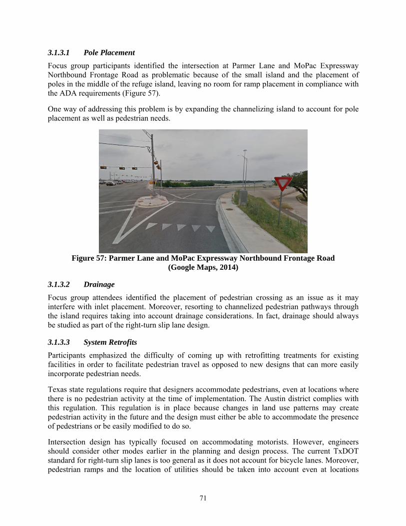
71
3.1.3.1 Pole Placement
Focus group participants identified the intersection at Parmer Lane and MoPac Expressway Northbound Frontage Road as problematic because of the small island and the placement of poles in the middle of the refuge island, leaving no room for ramp placement in compliance with the ADA requirements (Figure 57).
One way of addressing this problem is by expanding the channelizing island to account for pole placement as well as pedestrian needs.
Figure 57: Parmer Lane and MoPac Expressway Northbound Frontage Road
(Google Maps, 2014)
3.1.3.2 Drainage
Focus group attendees identified the placement of pedestrian crossing as an issue as it may interfere with inlet placement. Moreover, resorting to channelized pedestrian pathways through the island requires taking into account drainage considerations. In fact, drainage should always be studied as part of the right-turn slip lane design.
3.1.3.3 System Retrofits
Participants emphasized the difficulty of coming up with retrofitting treatments for existing facilities in order to facilitate pedestrian travel as opposed to new designs that can more easily incorporate pedestrian needs.
Texas state regulations require that designers accommodate pedestrians, even at locations where there is no pedestrian activity at the time of implementation. The Austin district complies with this regulation. This regulation is in place because changes in land use patterns may create pedestrian activity in the future and the design must either be able to accommodate the presence of pedestrians or be easily modified to do so.
Intersection design has typically focused on accommodating motorists. However, engineers should consider other modes earlier in the planning and design process. The current TxDOT standard for right-turn slip lanes is too general as it does not account for bicycle lanes. Moreover, pedestrian ramps and the location of utilities should be taken into account even at locations
72
where there is no pedestrian volume as pedestrian activity might develop over time. Design engineers need to prioritize pedestrians to prevent safety issues in the future. This issue is particularly pertinent in suburban or rural areas surrounding cities where pedestrian facilities may not be needed at the time of initial construction. Proactive planning and design can facilitate installation of pedestrian crossing treatments at a later date with limited disruption to the intersection and at a lower cost. Participants mentioned simple methods to facilitate future retrofits, such as properly placed drainage inlets, ramp installation without crosswalk markings and pole and sign placement out of the way of future sidewalks, landing areas, and/or pedestrian pathways.
Given the emphasis the focus group participants placed on identifying cost-effective retrofitting treatments and expanding on the preliminary guidelines produced, the research team undertook a literature review of retrofitting solutions applicable to right-turn slip lanes and decided to hold a second focus group meeting to discuss the findings with TxDOT engineers and planners.
3.2 Second Focus Group
3.2.1 Focus Group Setup The participants of the first meeting were invited back for a second focus group discussion concentrated on potential retrofitting solutions for existing intersections. The second focus group was held on June 10, 2014, at the CTR offices on The University of Texas at Austin campus from 9:00 a.m. until noon.
The total number of attendees at the focus group was 10: six affiliated with TxDOT and four affiliated with CTR.
Table 15 identifies the attendees, their titles, and their affiliations, as reported on the sign-in sheet.
Table 15: Second Focus Group Attendees Attendee Title Affiliation Chandra Bhat Researcher CTR Jennifer Duthie Research Supervisor CTR Chris Hehr Plan Development Section –
Design Division TxDOT - PMC
Mason Gemar Researcher CTR Robert Guydosh TxDOT Darrin Jensen Project Manager TxDOT - PMC Pete Krause Landscape Architect TxDOT Sonia Mercado Transportation Engineer TxDOT Leonard Polk Houston District Permit Section TxDOT Zeina Wafa Graduate Research Assistant CTR
3.2.2 Focus Group Proceedings This focus group meeting was centered on measures to retrofit existing right-turn slip lanes to accommodate pedestrians and improve overall safety. The participants were presented with proceedings from a Transportation Research Board (TRB) webinar, potential retrofitting
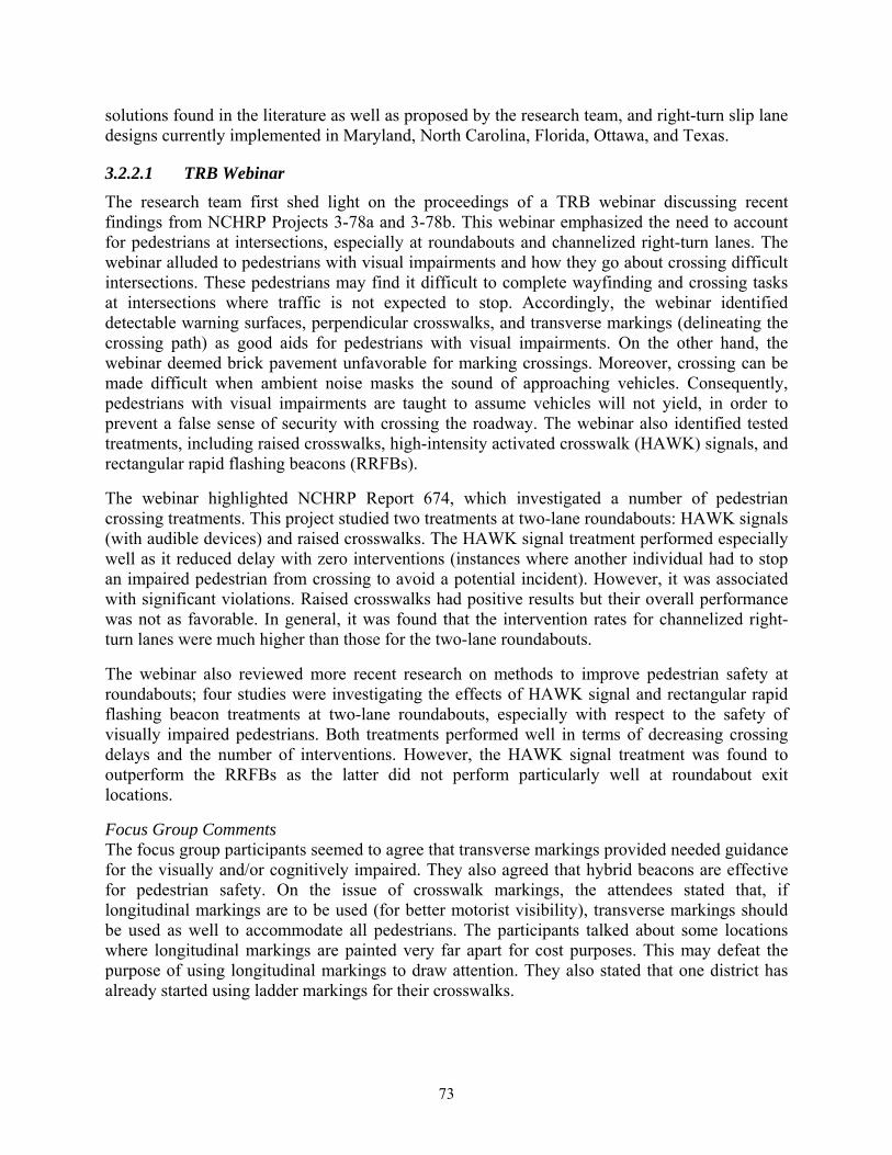
73
solutions found in the literature as well as proposed by the research team, and right-turn slip lane designs currently implemented in Maryland, North Carolina, Florida, Ottawa, and Texas.
3.2.2.1 TRB Webinar
The research team first shed light on the proceedings of a TRB webinar discussing recent findings from NCHRP Projects 3-78a and 3-78b. This webinar emphasized the need to account for pedestrians at intersections, especially at roundabouts and channelized right-turn lanes. The webinar alluded to pedestrians with visual impairments and how they go about crossing difficult intersections. These pedestrians may find it difficult to complete wayfinding and crossing tasks at intersections where traffic is not expected to stop. Accordingly, the webinar identified detectable warning surfaces, perpendicular crosswalks, and transverse markings (delineating the crossing path) as good aids for pedestrians with visual impairments. On the other hand, the webinar deemed brick pavement unfavorable for marking crossings. Moreover, crossing can be made difficult when ambient noise masks the sound of approaching vehicles. Consequently, pedestrians with visual impairments are taught to assume vehicles will not yield, in order to prevent a false sense of security with crossing the roadway. The webinar also identified tested treatments, including raised crosswalks, high-intensity activated crosswalk (HAWK) signals, and rectangular rapid flashing beacons (RRFBs).
The webinar highlighted NCHRP Report 674, which investigated a number of pedestrian crossing treatments. This project studied two treatments at two-lane roundabouts: HAWK signals (with audible devices) and raised crosswalks. The HAWK signal treatment performed especially well as it reduced delay with zero interventions (instances where another individual had to stop an impaired pedestrian from crossing to avoid a potential incident). However, it was associated with significant violations. Raised crosswalks had positive results but their overall performance was not as favorable. In general, it was found that the intervention rates for channelized right-turn lanes were much higher than those for the two-lane roundabouts.
The webinar also reviewed more recent research on methods to improve pedestrian safety at roundabouts; four studies were investigating the effects of HAWK signal and rectangular rapid flashing beacon treatments at two-lane roundabouts, especially with respect to the safety of visually impaired pedestrians. Both treatments performed well in terms of decreasing crossing delays and the number of interventions. However, the HAWK signal treatment was found to outperform the RRFBs as the latter did not perform particularly well at roundabout exit locations.
Focus Group Comments The focus group participants seemed to agree that transverse markings provided needed guidance for the visually and/or cognitively impaired. They also agreed that hybrid beacons are effective for pedestrian safety. On the issue of crosswalk markings, the attendees stated that, if longitudinal markings are to be used (for better motorist visibility), transverse markings should be used as well to accommodate all pedestrians. The participants talked about some locations where longitudinal markings are painted very far apart for cost purposes. This may defeat the purpose of using longitudinal markings to draw attention. They also stated that one district has already started using ladder markings for their crosswalks.
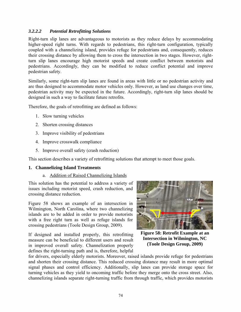
74
Figure 58: Retrofit Example at an Intersection in Wilmington, NC
(Toole Design Group, 2009)
3.2.2.2 Potential Retrofitting Solutions
Right-turn slip lanes are advantageous to motorists as they reduce delays by accommodating higher-speed right turns. With regards to pedestrians, this right-turn configuration, typically coupled with a channelizing island, provides refuge for pedestrians and, consequently, reduces their crossing distance by allowing them to cross the intersection in two stages. However, right-turn slip lanes encourage high motorist speeds and create conflict between motorists and pedestrians. Accordingly, they can be modified to reduce conflict potential and improve pedestrian safety.
Similarly, some right-turn slip lanes are found in areas with little or no pedestrian activity and are thus designed to accommodate motor vehicles only. However, as land use changes over time, pedestrian activity may be expected in the future. Accordingly, right-turn slip lanes should be designed in such a way to facilitate future retrofits.
Therefore, the goals of retrofitting are defined as follows:
1. Slow turning vehicles
2. Shorten crossing distances
3. Improve visibility of pedestrians
4. Improve crosswalk compliance
5. Improve overall safety (crash reduction)
This section describes a variety of retrofitting solutions that attempt to meet those goals.
1. Channelizing Island Treatments
a. Addition of Raised Channelizing Islands
This solution has the potential to address a variety of issues including motorist speed, crash reduction, and crossing distance reduction.
Figure 58 shows an example of an intersection in Wilmington, North Carolina, where two channelizing islands are to be added in order to provide motorists with a free right turn as well as refuge islands for crossing pedestrians (Toole Design Group, 2009).
If designed and installed properly, this retrofitting measure can be beneficial to different users and result in improved overall safety. Channelization properly defines the right-turning path and is, therefore, helpful for drivers, especially elderly motorists. Moreover, raised islands provide refuge for pedestrians and shorten their crossing distance. This reduced crossing distance may result in more optimal signal phases and control efficiency. Additionally, slip lanes can provide storage space for turning vehicles as they yield to oncoming traffic before they merge onto the cross street. Also, channelizing islands separate right-turning traffic from through traffic, which provides motorists
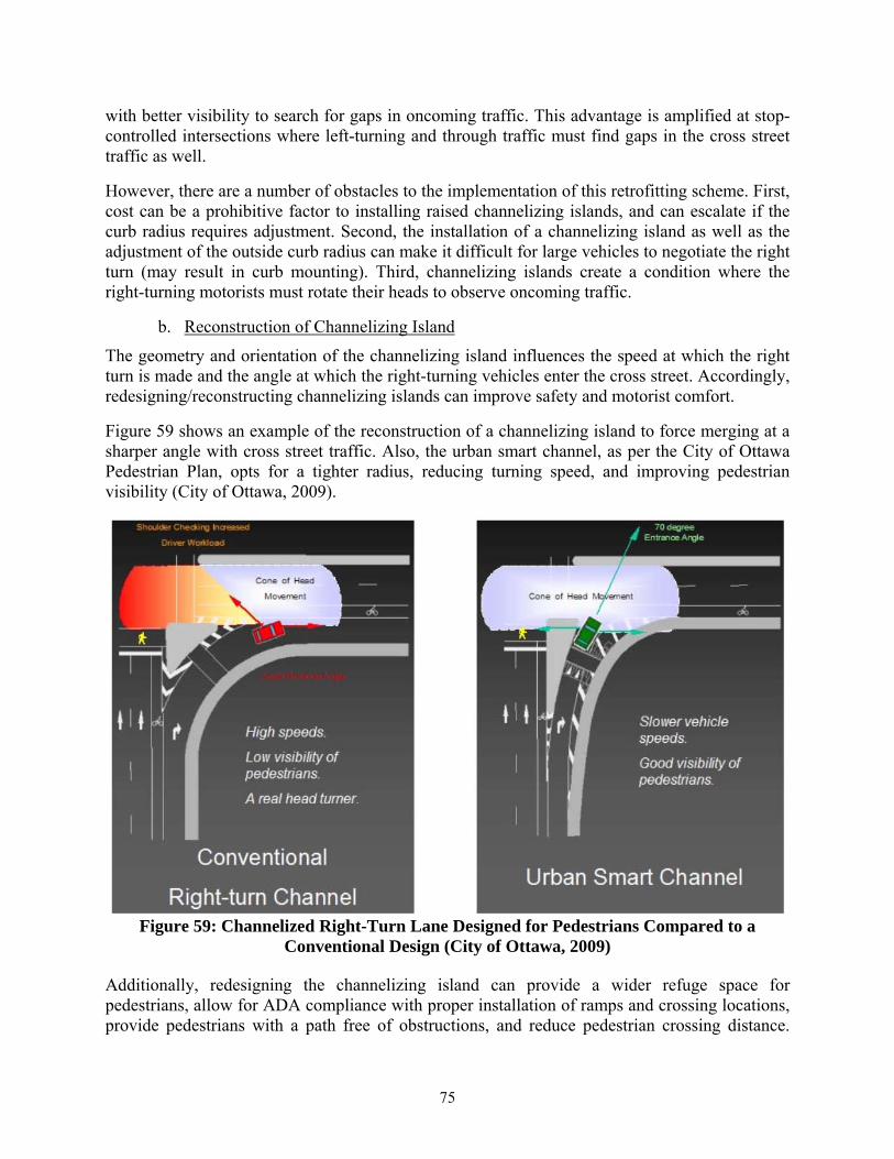
75
with better visibility to search for gaps in oncoming traffic. This advantage is amplified at stop-controlled intersections where left-turning and through traffic must find gaps in the cross street traffic as well.
However, there are a number of obstacles to the implementation of this retrofitting scheme. First, cost can be a prohibitive factor to installing raised channelizing islands, and can escalate if the curb radius requires adjustment. Second, the installation of a channelizing island as well as the adjustment of the outside curb radius can make it difficult for large vehicles to negotiate the right turn (may result in curb mounting). Third, channelizing islands create a condition where the right-turning motorists must rotate their heads to observe oncoming traffic.
b. Reconstruction of Channelizing Island
The geometry and orientation of the channelizing island influences the speed at which the right turn is made and the angle at which the right-turning vehicles enter the cross street. Accordingly, redesigning/reconstructing channelizing islands can improve safety and motorist comfort.
Figure 59 shows an example of the reconstruction of a channelizing island to force merging at a sharper angle with cross street traffic. Also, the urban smart channel, as per the City of Ottawa Pedestrian Plan, opts for a tighter radius, reducing turning speed, and improving pedestrian visibility (City of Ottawa, 2009).
Figure 59: Channelized Right-Turn Lane Designed for Pedestrians Compared to a
Conventional Design (City of Ottawa, 2009) Additionally, redesigning the channelizing island can provide a wider refuge space for pedestrians, allow for ADA compliance with proper installation of ramps and crossing locations, provide pedestrians with a path free of obstructions, and reduce pedestrian crossing distance.
76
Also, promoting entry into the cross street at a sharper angle improves pedestrian visibility and decreases the extent approaching drivers have to turn their heads to look for oncoming traffic.
Figure 60 illustrates another example of narrowing the turning path using pavement markings as per the Florida DOT right-turn slip lane design standards. In this example, the channelizing island is expanded using chevron pattern markings.
Figure 60: Extension of Island Using Striping as per the Florida Department of
Transportation Right-Turn Slip Lane Design (FDOT, 2014) Despite the many advantages associated with this retrofitting treatment, there are drawbacks to the implementation of this arrangement. First, although the initial cost may be low, additional pavement markings can be a maintenance burden and incur longer term costs. Second, the delineated path may not be followed by motorists who prefer to execute a higher speed turn and encroach on the markings, rendering the treatment ineffective. Any modification to the curb radius to inhibit this behavior would result in higher costs.
Focus Group Comments The focus group participants agreed that the Ottawa design is preferable. It was noted as being good for bike lane placement, limiting the necessity of drivers to turn their head to view oncoming traffic, promoting better visibility of pedestrians, and generally inhibiting higher speed turns. Comparing the Ottawa design with the Florida DOT design, TxDOT attendees seemed to favor the former as this configuration appears to require less right-of-way. Overall, this design, not requiring as much head turning, is suitable for the elderly as well as motorists with vision and neck problems. Participants speculated that the Florida DOT design may encourage noncompliance with the crosswalk location (to save on crossing distance) due to the provision of extra perceived refuge in the painted area of the island.
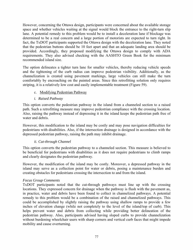
77
However, concerning the Ottawa design, participants were concerned about the available storage space and whether vehicles waiting at the signal would block the entrance to the right-turn slip lane. A potential remedy to this problem would be to install a deceleration lane if blockage was determined to be a real concern and a large portion of motorists are expected to turn right. In fact, the TxDOT participants supported the Ottawa design with the deceleration lane. They noted that the pedestrian buttons should be 10 feet apart and that an adequate landing area should be provided. Accordingly, they proposed modifying the Ottawa design to comply with ADA requirements. They also advised checking with the AASHTO Green Book for the minimum recommended island size.
The option delineates a tighter turn lane for smaller vehicles, thereby reducing vehicle speeds and the tightening of the curb radius can improve pedestrian visibility. Additionally, as the channelization is created using pavement markings, large vehicles can still make the turn comfortably by encroaching on the painted areas. Since this retrofitting solution only requires striping, it is a relatively low cost and easily implementable treatment (Figure 59).
c. Modifying Pedestrian Pathway
i. Raised Pathway
This option converts the pedestrian pathway in the island from a channeled section to a raised path. Such a retrofitting measure may improve pedestrian compliance with the crossing location. Also, raising the pathway instead of depressing it in the island keeps the pedestrian path free of water and debris.
However, this modification to the island may be costly and may pose navigation difficulties for pedestrians with disabilities. Also, if the intersection drainage is designed in accordance with the depressed pedestrian pathway, raising the path may inhibit drainage.
ii. Cut-through Channel
This option converts the pedestrian pathway to a channeled section. This measure is believed to be beneficial for pedestrians with disabilities as it does not require pedestrians to climb ramps and clearly designates the pedestrian pathway.
However, the modification of the island may be costly. Moreover, a depressed pathway in the island may serve as a collection point for water or debris, posing a maintenance burden and creating obstacles for pedestrians crossing the intersection to and from the island.
Focus Group Comments TxDOT participants noted that the cut-through pathways must line up with the crossing locations. They expressed concern for drainage when the pathway is flush with the pavement as, in practice, water and debris have been found to collect in channelized pathways. A potential remedy to this problem would be a combination of the raised and channelized pathways. This could be accomplished by slightly raising the pathway using shallow ramps to provide a few inches of elevation change (while not completely to the level of the island/top of curb). This helps prevent water and debris from collecting while providing better delineation of the pedestrian pathway. Also, participants advised having sloped curbs to provide channelization without burdening wheelchair users with sharp corners and vertical curb faces that might impede mobility and cause overturning.
78
d. Provision of Pedestrian Features
This option is also expected to improve pedestrian compliance with the crossing location. Pedestrian features that increase compliance include proper sidewalk widths, landing areas, and ramps with detection. This retrofitting scheme aims at accommodating pedestrians and complying with ADA requirements. Also, this option serves increased pedestrian activity in the future.
However, the investment in retrofitting right-turn slip lanes at intersections with no observed pedestrian activity may not be justified.
Focus Group Comments Focus group participants noted that the sole of a person’s shoe affects the ability to feel and differentiate the detectable warning surface from the adjacent sidewalk, potentially making it more difficult for the visually impaired to orient themselves appropriately to cross the intersection.
2. Crosswalk Treatments
Crosswalk adjustments are intended to improve pedestrian visibility as well as pedestrian compliance. Also, the orientation of the crosswalk affects the pedestrian crossing distance.
a. Crosswalk Placement at Upstream End of Turning Roadway
The advantages of this crosswalk alignment are that it promotes better visibility of pedestrians, provides adequate storage downstream of the crosswalk for yielding vehicles, and separates motorist decisions (movies yielding to cross street and associated action downstream of pedestrian crossing and, therefore, drivers are less likely to be looking away from pedestrians crossing from the right).
On the other hand, the disadvantages of this option are that it might not be along the natural walking path (encouraging non-compliance), may require reconstruction of ramps/sidewalks, may be an issue with the superelevation of the turning roadway versus the adjacent roadway cross-slope, and may not be compatible with drainage/inlet locations. Also, this configuration, along with the island geometry, may not accommodate an adequate landing area to be compliant with ADA requirements.
Focus Group Comments TxDOT participants stated that this configuration may not allow for an appropriate landing area in the island.
b. Crosswalk Placement at Center of Turning Roadway
This crosswalk configuration should provide adequate storage for at least one vehicle beyond the crosswalk.
If installed properly, this option can provide adequate storage for vehicles yielding to cross street traffic without blocking the crosswalk. Also, this option improves motorist visibility of the crossing location. Moreover, the location of the crosswalk ensures that motorists are focusing on pedestrians crossing the lane before shifting their focus downstream on the oncoming traffic. Furthermore, this configuration is better for compatibility with superelevation along turning
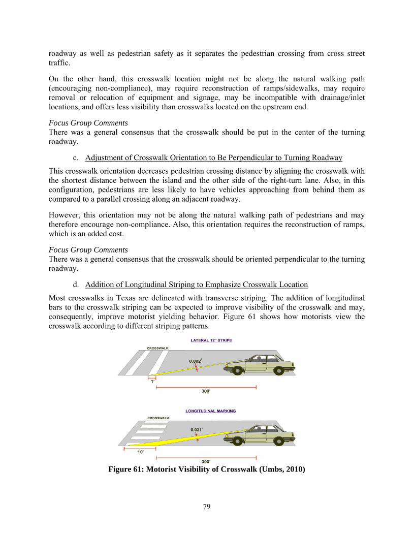
79
roadway as well as pedestrian safety as it separates the pedestrian crossing from cross street traffic.
On the other hand, this crosswalk location might not be along the natural walking path (encouraging non-compliance), may require reconstruction of ramps/sidewalks, may require removal or relocation of equipment and signage, may be incompatible with drainage/inlet locations, and offers less visibility than crosswalks located on the upstream end.
Focus Group Comments There was a general consensus that the crosswalk should be put in the center of the turning roadway.
c. Adjustment of Crosswalk Orientation to Be Perpendicular to Turning Roadway
This crosswalk orientation decreases pedestrian crossing distance by aligning the crosswalk with the shortest distance between the island and the other side of the right-turn lane. Also, in this configuration, pedestrians are less likely to have vehicles approaching from behind them as compared to a parallel crossing along an adjacent roadway.
However, this orientation may not be along the natural walking path of pedestrians and may therefore encourage non-compliance. Also, this orientation requires the reconstruction of ramps, which is an added cost.
Focus Group Comments There was a general consensus that the crosswalk should be oriented perpendicular to the turning roadway.
d. Addition of Longitudinal Striping to Emphasize Crosswalk Location
Most crosswalks in Texas are delineated with transverse striping. The addition of longitudinal bars to the crosswalk striping can be expected to improve visibility of the crosswalk and may, consequently, improve motorist yielding behavior. Figure 61 shows how motorists view the crosswalk according to different striping patterns.
Figure 61: Motorist Visibility of Crosswalk (Umbs, 2010)
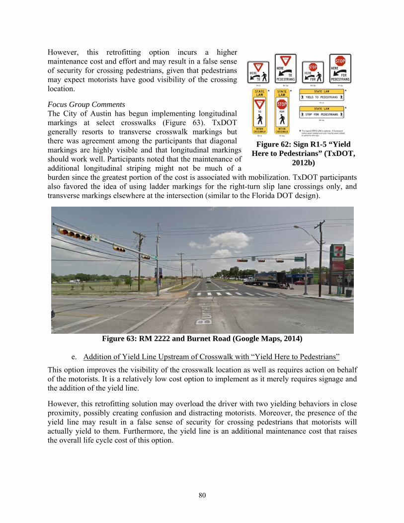
80
However, this retrofitting option incurs a higher maintenance cost and effort and may result in a false sense of security for crossing pedestrians, given that pedestrians may expect motorists have good visibility of the crossing location.
Focus Group Comments The City of Austin has begun implementing longitudinal markings at select crosswalks (Figure 63). TxDOT generally resorts to transverse crosswalk markings but there was agreement among the participants that diagonal markings are highly visible and that longitudinal markings should work well. Participants noted that the maintenance of additional longitudinal striping might not be much of a burden since the greatest portion of the cost is associated with mobilization. TxDOT participants also favored the idea of using ladder markings for the right-turn slip lane crossings only, and transverse markings elsewhere at the intersection (similar to the Florida DOT design).
Figure 63: RM 2222 and Burnet Road (Google Maps, 2014)
e. Addition of Yield Line Upstream of Crosswalk with “Yield Here to Pedestrians”
This option improves the visibility of the crosswalk location as well as requires action on behalf of the motorists. It is a relatively low cost option to implement as it merely requires signage and the addition of the yield line.
However, this retrofitting solution may overload the driver with two yielding behaviors in close proximity, possibly creating confusion and distracting motorists. Moreover, the presence of the yield line may result in a false sense of security for crossing pedestrians that motorists will actually yield to them. Furthermore, the yield line is an additional maintenance cost that raises the overall life cycle cost of this option.
Figure 62: Sign R1-5 “Yield Here to Pedestrians” (TxDOT,
2012b)
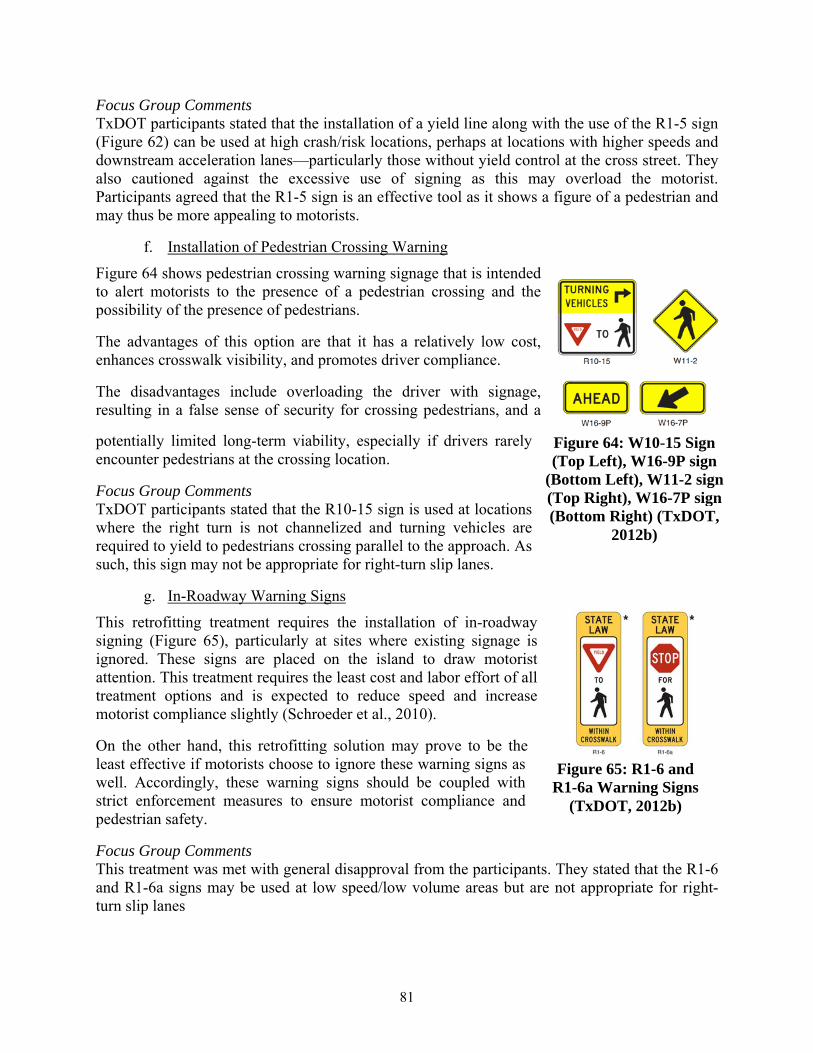
81
Focus Group Comments TxDOT participants stated that the installation of a yield line along with the use of the R1-5 sign (Figure 62) can be used at high crash/risk locations, perhaps at locations with higher speeds and downstream acceleration lanes—particularly those without yield control at the cross street. They also cautioned against the excessive use of signing as this may overload the motorist. Participants agreed that the R1-5 sign is an effective tool as it shows a figure of a pedestrian and may thus be more appealing to motorists.
f. Installation of Pedestrian Crossing Warning
Figure 64 shows pedestrian crossing warning signage that is intended to alert motorists to the presence of a pedestrian crossing and the possibility of the presence of pedestrians.
The advantages of this option are that it has a relatively low cost, enhances crosswalk visibility, and promotes driver compliance.
The disadvantages include overloading the driver with signage, resulting in a false sense of security for crossing pedestrians, and a
potentially limited long-term viability, especially if drivers rarely encounter pedestrians at the crossing location.
Focus Group Comments TxDOT participants stated that the R10-15 sign is used at locations where the right turn is not channelized and turning vehicles are required to yield to pedestrians crossing parallel to the approach. As such, this sign may not be appropriate for right-turn slip lanes.
g. In-Roadway Warning Signs
This retrofitting treatment requires the installation of in-roadway signing (Figure 65), particularly at sites where existing signage is ignored. These signs are placed on the island to draw motorist attention. This treatment requires the least cost and labor effort of all treatment options and is expected to reduce speed and increase motorist compliance slightly (Schroeder et al., 2010).
On the other hand, this retrofitting solution may prove to be the least effective if motorists choose to ignore these warning signs as well. Accordingly, these warning signs should be coupled with strict enforcement measures to ensure motorist compliance and pedestrian safety.
Focus Group Comments This treatment was met with general disapproval from the participants. They stated that the R1-6 and R1-6a signs may be used at low speed/low volume areas but are not appropriate for right-turn slip lanes
Figure 64: W10-15 Sign (Top Left), W16-9P sign
(Bottom Left), W11-2 sign (Top Right), W16-7P sign (Bottom Right) (TxDOT,
2012b)
Figure 65: R1-6 and R1-6a Warning Signs
(TxDOT, 2012b)
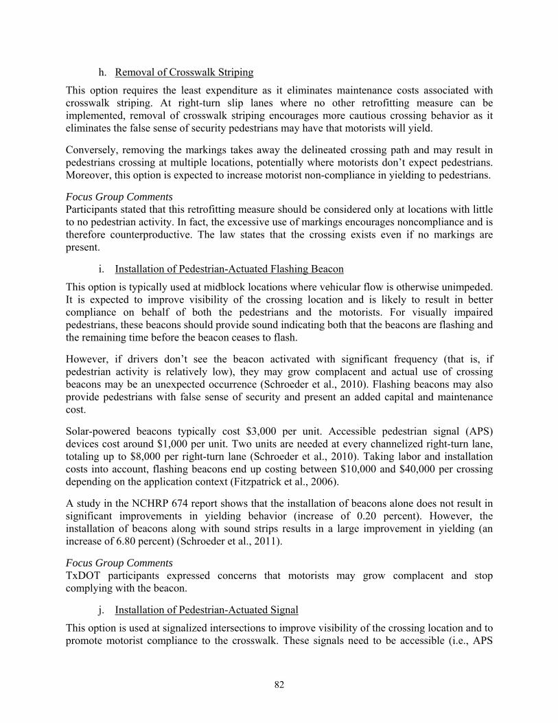
82
h. Removal of Crosswalk Striping
This option requires the least expenditure as it eliminates maintenance costs associated with crosswalk striping. At right-turn slip lanes where no other retrofitting measure can be implemented, removal of crosswalk striping encourages more cautious crossing behavior as it eliminates the false sense of security pedestrians may have that motorists will yield.
Conversely, removing the markings takes away the delineated crossing path and may result in pedestrians crossing at multiple locations, potentially where motorists don’t expect pedestrians. Moreover, this option is expected to increase motorist non-compliance in yielding to pedestrians.
Focus Group Comments Participants stated that this retrofitting measure should be considered only at locations with little to no pedestrian activity. In fact, the excessive use of markings encourages noncompliance and is therefore counterproductive. The law states that the crossing exists even if no markings are present.
i. Installation of Pedestrian-Actuated Flashing Beacon
This option is typically used at midblock locations where vehicular flow is otherwise unimpeded. It is expected to improve visibility of the crossing location and is likely to result in better compliance on behalf of both the pedestrians and the motorists. For visually impaired pedestrians, these beacons should provide sound indicating both that the beacons are flashing and the remaining time before the beacon ceases to flash.
However, if drivers don’t see the beacon activated with significant frequency (that is, if pedestrian activity is relatively low), they may grow complacent and actual use of crossing beacons may be an unexpected occurrence (Schroeder et al., 2010). Flashing beacons may also provide pedestrians with false sense of security and present an added capital and maintenance cost.
Solar-powered beacons typically cost $3,000 per unit. Accessible pedestrian signal (APS) devices cost around $1,000 per unit. Two units are needed at every channelized right-turn lane, totaling up to $8,000 per right-turn lane (Schroeder et al., 2010). Taking labor and installation costs into account, flashing beacons end up costing between $10,000 and $40,000 per crossing depending on the application context (Fitzpatrick et al., 2006).
A study in the NCHRP 674 report shows that the installation of beacons alone does not result in significant improvements in yielding behavior (increase of 0.20 percent). However, the installation of beacons along with sound strips results in a large improvement in yielding (an increase of 6.80 percent) (Schroeder et al., 2011).
Focus Group Comments TxDOT participants expressed concerns that motorists may grow complacent and stop complying with the beacon.
j. Installation of Pedestrian-Actuated Signal
This option is used at signalized intersections to improve visibility of the crossing location and to promote motorist compliance to the crosswalk. These signals need to be accessible (i.e., APS
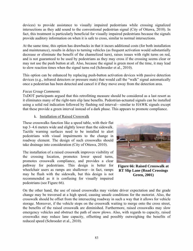
83
devices) to provide assistance to visually impaired pedestrians while crossing signalized intersections as they add sound to the conventional pedestrian signal (City of Ottawa, 2010). In fact, this treatment is particularly beneficial for visually impaired pedestrians because the signals provide auditory information on when it is safe to cross, similar to normal intersections.
At the same time, this option has drawbacks in that it incurs additional costs (for both installation and maintenance), results in delays to turning vehicles (as frequent activation would substantially decrease or eliminate the benefit of the channelized turn), raises issues with right turns on red, and is not guaranteed to be used by pedestrians as they may cross if the crossing seems clear or may not use the push button at all. Also, because the signal is green most of the time, it may lead to slow reaction times when the signal turns red (Schroeder et al., 2010).
This option can be enhanced by replacing push-button activation devices with passive detection devices (e.g., infrared detectors or pressure mats) that would call the “walk” signal automatically once a pedestrian has been detected and cancel it if they move away from the detection area.
Focus Group Comments TxDOT participants argued that this retrofitting measure should be considered as a last resort as it eliminates many of the right-turn slip lane benefits. Pedestrian-actuated signals can be installed using a solid red indication followed by flashing red interval—similar to HAWK signals except that these provide a green interval instead of a dark phase. This appears to promote compliance.
k. Installation of Raised Crosswalk
These crosswalks function like a speed table, with their flat top 3–4.6 meters wide and slightly lower than the sidewalk. Tactile warning surfaces need to be installed to alert pedestrians with visual impairments to the change in roadway element. The design of such crosswalks should take drainage into consideration (City of Ottawa, 2010).
The installation of a raised crosswalk improves visibility of the crossing location, promotes lower speed turns, promotes crosswalk compliance, and provides a clear pathway for pedestrians. This design is better for wheelchair users as ramps are shallower—in fact, ramps may be flush with the sidewalk, but this design is not recommended as it is confusing for visually impaired pedestrians (see Figure 66).
On the other hand, the use of raised crosswalks may violate driver expectation and the grade change may be traversed at a high speed, causing unsafe conditions for the motorist. Also, the crosswalk should be offset from the intersecting roadway in such a way that it allows for vehicle storage. Moreover, if the vehicle stops on the crosswalk waiting to merge onto the cross street, the benefits of the raised crosswalk are diminished. Furthermore, raised crosswalks may slow emergency vehicles and obstruct the path of snow plows. Also, with regards to capacity, raised crosswalks may reduce lane capacity, offsetting and possibly outweighing the benefits of reduced speed (Schroeder et al., 2010).
Figure 66: Raised Crosswalk at RT Slip Lane (Road Crossings
Green, 2001)
84
Such a treatment costs around $5,000 including material and labor costs. This cost estimate does not include drainage alterations (Schroeder et al., 2010).
Focus Group Comments Participants stated that this retrofitting measure may be difficult to implement at some locations due to drainage concerns. If the goal is to slow down motorists, this option seems to be a good treatment. However, it may be problematic at high-speed locations. Consequently, designers need to consider the ability of drivers to slow down in advance without impeding through traffic.
l. Texturing Crosswalks
This option enhances the visibility of crosswalks and alerts motorists of the presence of a pedestrian crossing. Textured crosswalks should be coupled with reflective pavement markings so that the crosswalk remains visible at night. Textured crosswalks also cause vibrations when vehicles drive over them and serve as a reminder for the presence of pedestrians in the area (City of Ottawa, 2010).
However, there are costs associated with the installation and maintenance of this facility and the vibrations can lead to driver discomfort and noise.
Focus Group Comments Participants stated that this treatment may not generate as many concerns as previously thought as most installed surfaces are made slip resistant.
m. Sound Strips/Rumble Strips
This retrofitting solution results in auditory cues for both pedestrians and motorists. On the one hand, the sound resulting from a vehicle traversing the roadway section with rumble strips alerts the pedestrian of an approaching vehicle so that they cross with care. The sound signals to the motorist that they must slow down and alerts them of a possible crossing ahead (Schroeder et al., 2010).
However, as stated in the first focus group, this solution is usually contested due to the noise it produces and its potential of collecting water inside the pavement.
Figure 67 shows an implementation of sound strips in Charlotte, North Carolina. The Charlotte Department of Transportation paid less than $1,000 for the materials. Accordingly, this option is a relatively low cost treatment initially but may incur maintenance costs over time.
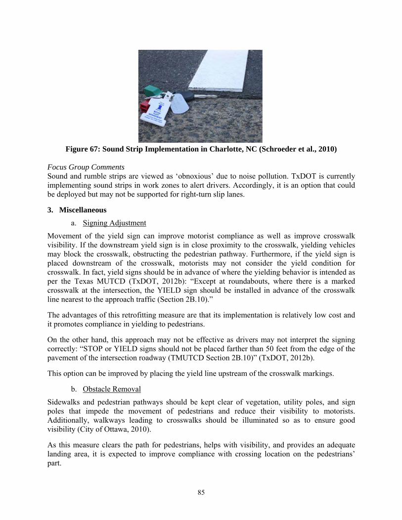
85
Figure 67: Sound Strip Implementation in Charlotte, NC (Schroeder et al., 2010)
Focus Group Comments Sound and rumble strips are viewed as ‘obnoxious’ due to noise pollution. TxDOT is currently implementing sound strips in work zones to alert drivers. Accordingly, it is an option that could be deployed but may not be supported for right-turn slip lanes.
3. Miscellaneous
a. Signing Adjustment
Movement of the yield sign can improve motorist compliance as well as improve crosswalk visibility. If the downstream yield sign is in close proximity to the crosswalk, yielding vehicles may block the crosswalk, obstructing the pedestrian pathway. Furthermore, if the yield sign is placed downstream of the crosswalk, motorists may not consider the yield condition for crosswalk. In fact, yield signs should be in advance of where the yielding behavior is intended as per the Texas MUTCD (TxDOT, 2012b): “Except at roundabouts, where there is a marked crosswalk at the intersection, the YIELD sign should be installed in advance of the crosswalk line nearest to the approach traffic (Section 2B.10).”
The advantages of this retrofitting measure are that its implementation is relatively low cost and it promotes compliance in yielding to pedestrians.
On the other hand, this approach may not be effective as drivers may not interpret the signing correctly: “STOP or YIELD signs should not be placed farther than 50 feet from the edge of the pavement of the intersection roadway (TMUTCD Section 2B.10)” (TxDOT, 2012b).
This option can be improved by placing the yield line upstream of the crosswalk markings.
b. Obstacle Removal
Sidewalks and pedestrian pathways should be kept clear of vegetation, utility poles, and sign poles that impede the movement of pedestrians and reduce their visibility to motorists. Additionally, walkways leading to crosswalks should be illuminated so as to ensure good visibility (City of Ottawa, 2010).
As this measure clears the path for pedestrians, helps with visibility, and provides an adequate landing area, it is expected to improve compliance with crossing location on the pedestrians’ part.
86
However, this approach may require relocation of utilities or signal poles, which may be cost prohibitive or disruptive to the traffic operations at the right-turn slip lane. Moreover, the island may not have sufficient space for sign or equipment relocation (accounting for proper offsets from curb) and may require adjusting existing sidewalks, landing areas, and/or ramps.
Focus Group Comments This treatment was generally favored by focus group participants where obstructions in the pedestrian pathway are an issue.
c. Posting Lower Speed Limits
This traffic-calming measure requires only the placement of regulatory signs dictating a lower speed limit than what is typical on urban roadways (15–25 mph). The main advantage of this treatment is that it is a low-cost measure that aims at improving pedestrian safety by slowing motorists down.
However, the effectiveness of this retrofitting solution is highly dependent on motorist compliance with the posted speed limit and enforcement. Moreover, a channelized right-turn lane cannot have a lower speed limit than the main roadway. Hence, such signs may be confusing to the motorist and may not result in the anticipated benefits (Schroeder et al., 2010).
Focus Group Comments Participants argued that speed limit reduction is difficult to impose successful and is likely to be rejected. Another approach may be to use an advisory speed sign for right-turn slip lanes instead of posting changes on the cross streets.
4. Auxiliary Lanes
a. Addition of Deceleration Lane
Deceleration lanes are typically expected to slow the turning vehicles, decrease vehicle crashes—especially rear-end crashes—by separating right-turning traffic from through traffic, reduce vehicular delays, and improve visibility for pedestrians. Deceleration lanes allow for storage and may reduce vehicular speeds depending on lane width and curb radius. Also, pedestrians can easily identify a turning vehicular by looking at the deceleration lane without having to anticipate whether a vehicle is turning or not. This benefit is further magnified by the use of auditory treatments that alert both pedestrian and motorist of each other’s presence (Schroeder et al., 2010).
However, the use of deceleration lanes is costly because it may require right-of-way acquisition. Though this configuration may reduce rear-end collisions, it may increase side-swipe crashes as vehicles change lanes to enter the deceleration lane. Also, the lane width-curb radius combination may promote higher vehicular speeds, jeopardizing the safety of crossing pedestrians. Deceleration lanes can be confused for through lanes and can be used, during congested conditions, to bypass queues at the intersection.
Focus Group Comments TxDOT generally supports the use of deceleration lanes as they appear to have very few disadvantages when warranted. These lanes may be less confusing to motorists with advanced signing (lane use or lane drop signage) and adequate deceleration bay lengths.
87
b. Removal of Acceleration Lane
Acceleration lanes typically increase motorists’ comfort by delaying the merging point further downstream after the right-turning vehicles have already entered the cross street. Accordingly, the presence of acceleration lanes promotes higher turn speeds as vehicles do not have to slow down in order to yield for oncoming traffic. Hence, from a pedestrian standpoint, acceleration lanes are problematic and their removal can be a means of improving pedestrian safety at right-turn slip lanes. This option may reduce the speed of turning vehicles and reduces the risk of side-swipe crashes along the cross street.
On the other hand, the removal of these lanes inhibits the mobility of motorists and is not favorable for merging vehicles, particularly on high-speed facilities. Acceleration lanes are generally beneficial to elderly drivers.
Focus Group Comments TxDOT participants mentioned that inconsistent driver behavior at acceleration lanes is an issue: some drivers stop and look for oncoming traffic while others proceed with intent to merge farther downstream (potential conflict/rear-end collision risk). The removal of the acceleration lane helps establish consistency and results in more predictable driver behavior.
5. Slip Lane Removal
If the right-turn slip lane geometry is especially problematic for pedestrians, particularly those who are visually impaired, one retrofitting solution would be to close the slip lane. This would eliminate the problems associated with it and reduce pedestrian crossing distances. Moreover, in lieu of the slip lane, this area can be reconstructed into a pedestrian-friendly corner with street furniture, benches, and plantation.
Where the slip lane removal is not feasible due to its negative impacts on traffic throughput and operations, several measures can be taken to enhance pedestrian safety. These include signalizing the right-turn slip lane to create ‘safe’ gaps for pedestrians to cross, raising the crosswalk and extending it from the sidewalk to the refuge island, and using warning signage to alert motorists of the presence of a pedestrian crossing (Hondrop, et al., 2010).
Figure 68 shows an example of how a slip lane can be removed and the space better utilized to serve pedestrian needs. The proposal shows that an emergency lane is kept so that emergency vehicles can reach the apartment complex on the corner of the intersection. However, the slip lane is no longer open for general traffic. This proposal emerged based on the number of collisions at this corner due to poor pedestrian visibility (Miller, 2014).
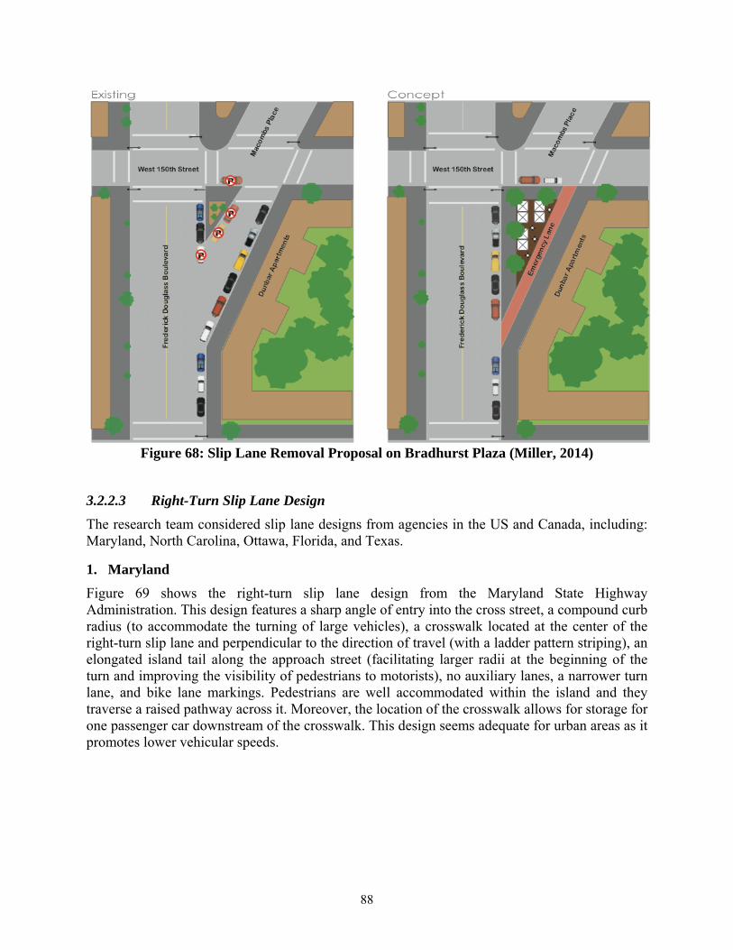
88
Figure 68: Slip Lane Removal Proposal on Bradhurst Plaza (Miller, 2014)
3.2.2.3 Right-Turn Slip Lane Design
The research team considered slip lane designs from agencies in the US and Canada, including: Maryland, North Carolina, Ottawa, Florida, and Texas.
1. Maryland
Figure 69 shows the right-turn slip lane design from the Maryland State Highway Administration. This design features a sharp angle of entry into the cross street, a compound curb radius (to accommodate the turning of large vehicles), a crosswalk located at the center of the right-turn slip lane and perpendicular to the direction of travel (with a ladder pattern striping), an elongated island tail along the approach street (facilitating larger radii at the beginning of the turn and improving the visibility of pedestrians to motorists), no auxiliary lanes, a narrower turn lane, and bike lane markings. Pedestrians are well accommodated within the island and they traverse a raised pathway across it. Moreover, the location of the crosswalk allows for storage for one passenger car downstream of the crosswalk. This design seems adequate for urban areas as it promotes lower vehicular speeds.
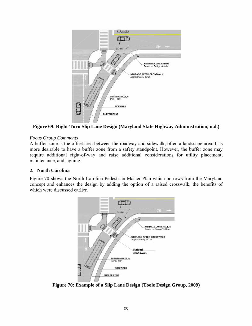
89
Figure 69: Right-Turn Slip Lane Design (Maryland State Highway Administration, n.d.)
Focus Group Comments A buffer zone is the offset area between the roadway and sidewalk, often a landscape area. It is more desirable to have a buffer zone from a safety standpoint. However, the buffer zone may require additional right-of-way and raise additional considerations for utility placement, maintenance, and signing.
2. North Carolina
Figure 70 shows the North Carolina Pedestrian Master Plan which borrows from the Maryland concept and enhances the design by adding the option of a raised crosswalk, the benefits of which were discussed earlier.
Figure 70: Example of a Slip Lane Design (Toole Design Group, 2009)
Raised crosswalk
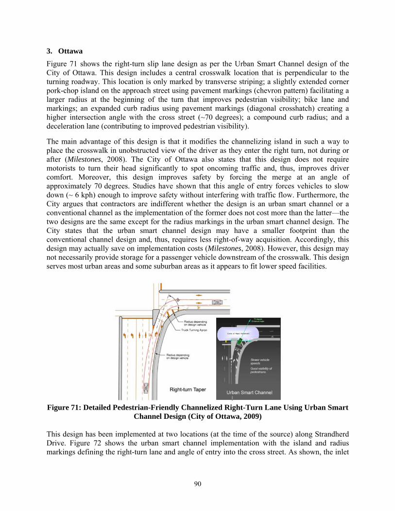
90
3. Ottawa
Figure 71 shows the right-turn slip lane design as per the Urban Smart Channel design of the City of Ottawa. This design includes a central crosswalk location that is perpendicular to the turning roadway. This location is only marked by transverse striping; a slightly extended corner pork-chop island on the approach street using pavement markings (chevron pattern) facilitating a larger radius at the beginning of the turn that improves pedestrian visibility; bike lane and markings; an expanded curb radius using pavement markings (diagonal crosshatch) creating a higher intersection angle with the cross street (~70 degrees); a compound curb radius; and a deceleration lane (contributing to improved pedestrian visibility).
The main advantage of this design is that it modifies the channelizing island in such a way to place the crosswalk in unobstructed view of the driver as they enter the right turn, not during or after (Milestones, 2008). The City of Ottawa also states that this design does not require motorists to turn their head significantly to spot oncoming traffic and, thus, improves driver comfort. Moreover, this design improves safety by forcing the merge at an angle of approximately 70 degrees. Studies have shown that this angle of entry forces vehicles to slow down (~ 6 kph) enough to improve safety without interfering with traffic flow. Furthermore, the City argues that contractors are indifferent whether the design is an urban smart channel or a conventional channel as the implementation of the former does not cost more than the latter—the two designs are the same except for the radius markings in the urban smart channel design. The City states that the urban smart channel design may have a smaller footprint than the conventional channel design and, thus, requires less right-of-way acquisition. Accordingly, this design may actually save on implementation costs (Milestones, 2008). However, this design may not necessarily provide storage for a passenger vehicle downstream of the crosswalk. This design serves most urban areas and some suburban areas as it appears to fit lower speed facilities.
Figure 71: Detailed Pedestrian-Friendly Channelized Right-Turn Lane Using Urban Smart
Channel Design (City of Ottawa, 2009) This design has been implemented at two locations (at the time of the source) along Strandherd Drive. Figure 72 shows the urban smart channel implementation with the island and radius markings defining the right-turn lane and angle of entry into the cross street. As shown, the inlet
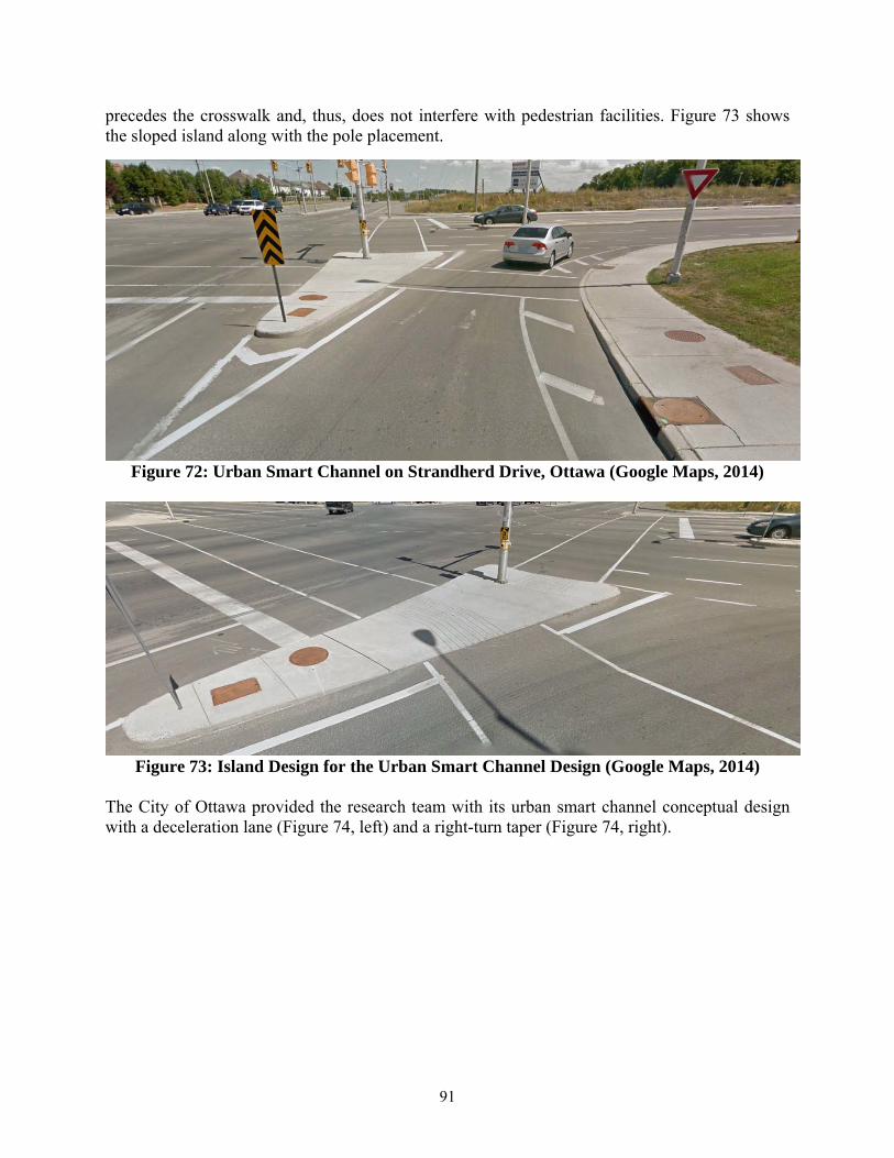
91
precedes the crosswalk and, thus, does not interfere with pedestrian facilities. Figure 73 shows the sloped island along with the pole placement.
Figure 72: Urban Smart Channel on Strandherd Drive, Ottawa (Google Maps, 2014)
Figure 73: Island Design for the Urban Smart Channel Design (Google Maps, 2014)
The City of Ottawa provided the research team with its urban smart channel conceptual design with a deceleration lane (Figure 74, left) and a right-turn taper (Figure 74, right).
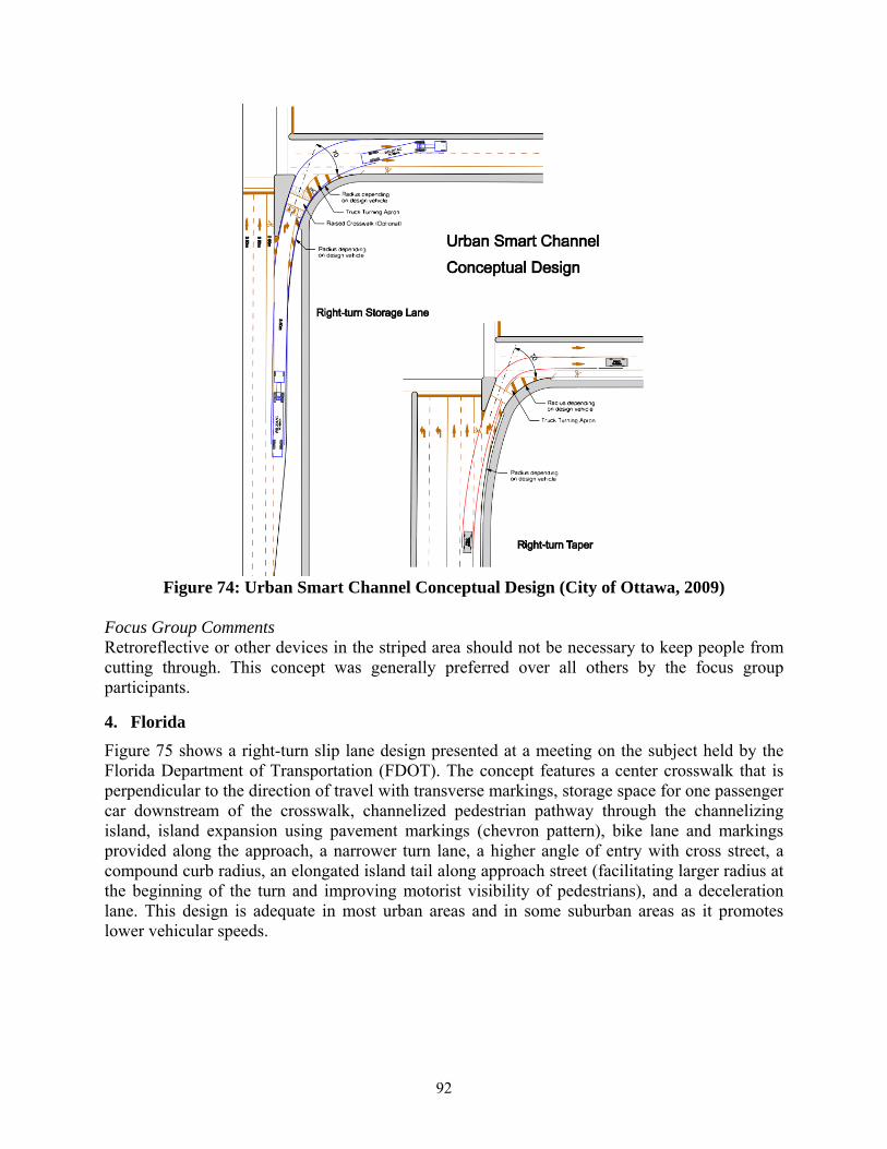
92
Figure 74: Urban Smart Channel Conceptual Design (City of Ottawa, 2009)
Focus Group Comments Retroreflective or other devices in the striped area should not be necessary to keep people from cutting through. This concept was generally preferred over all others by the focus group participants.
4. Florida
Figure 75 shows a right-turn slip lane design presented at a meeting on the subject held by the Florida Department of Transportation (FDOT). The concept features a center crosswalk that is perpendicular to the direction of travel with transverse markings, storage space for one passenger car downstream of the crosswalk, channelized pedestrian pathway through the channelizing island, island expansion using pavement markings (chevron pattern), bike lane and markings provided along the approach, a narrower turn lane, a higher angle of entry with cross street, a compound curb radius, an elongated island tail along approach street (facilitating larger radius at the beginning of the turn and improving motorist visibility of pedestrians), and a deceleration lane. This design is adequate in most urban areas and in some suburban areas as it promotes lower vehicular speeds.
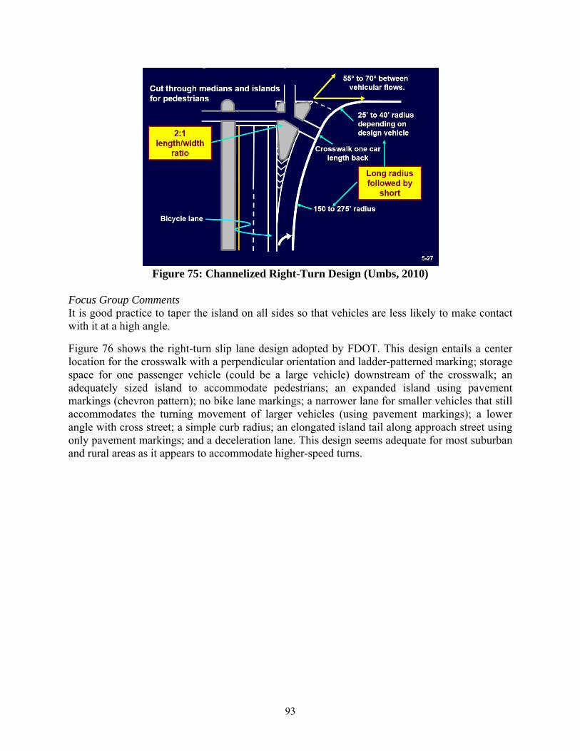
93
Figure 75: Channelized Right-Turn Design (Umbs, 2010)
Focus Group Comments It is good practice to taper the island on all sides so that vehicles are less likely to make contact with it at a high angle.
Figure 76 shows the right-turn slip lane design adopted by FDOT. This design entails a center location for the crosswalk with a perpendicular orientation and ladder-patterned marking; storage space for one passenger vehicle (could be a large vehicle) downstream of the crosswalk; an adequately sized island to accommodate pedestrians; an expanded island using pavement markings (chevron pattern); no bike lane markings; a narrower lane for smaller vehicles that still accommodates the turning movement of larger vehicles (using pavement markings); a lower angle with cross street; a simple curb radius; an elongated island tail along approach street using only pavement markings; and a deceleration lane. This design seems adequate for most suburban and rural areas as it appears to accommodate higher-speed turns.
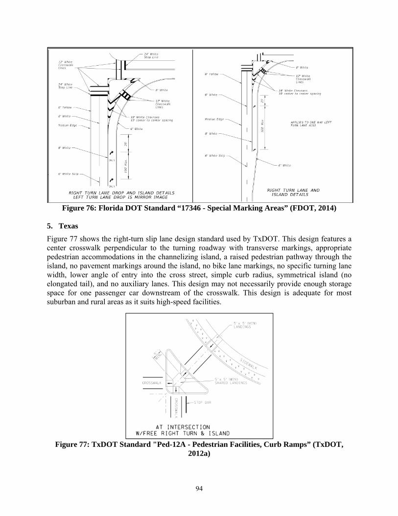
94
Figure 76: Florida DOT Standard “17346 - Special Marking Areas” (FDOT, 2014)
5. Texas
Figure 77 shows the right-turn slip lane design standard used by TxDOT. This design features a center crosswalk perpendicular to the turning roadway with transverse markings, appropriate pedestrian accommodations in the channelizing island, a raised pedestrian pathway through the island, no pavement markings around the island, no bike lane markings, no specific turning lane width, lower angle of entry into the cross street, simple curb radius, symmetrical island (no elongated tail), and no auxiliary lanes. This design may not necessarily provide enough storage space for one passenger car downstream of the crosswalk. This design is adequate for most suburban and rural areas as it suits high-speed facilities.
Figure 77: TxDOT Standard "Ped-12A - Pedestrian Facilities, Curb Ramps” (TxDOT,
2012a)
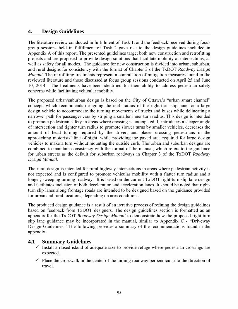
95
4. Design Guidelines
The literature review conducted in fulfillment of Task 1, and the feedback received during focus group sessions held in fulfillment of Task 2 gave rise to the design guidelines included in Appendix A of this report. The presented guidelines target both new construction and retrofitting projects and are proposed to provide design solutions that facilitate mobility at intersections, as well as safety for all modes. The guidance for new construction is divided into urban, suburban, and rural designs for consistency with the format of Chapter 3 of the TxDOT Roadway Design Manual. The retrofitting treatments represent a compilation of mitigation measures found in the reviewed literature and those discussed at focus group sessions conducted on April 25 and June 10, 2014. The treatments have been identified for their ability to address pedestrian safety concerns while facilitating vehicular mobility.
The proposed urban/suburban design is based on the City of Ottawa’s “urban smart channel” concept, which recommends designing the curb radius of the right-turn slip lane for a large design vehicle to accommodate the turning movements of trucks and buses while delineating a narrower path for passenger cars by striping a smaller inner turn radius. This design is intended to promote pedestrian safety in areas where crossing is anticipated. It introduces a steeper angle of intersection and tighter turn radius to promote slower turns by smaller vehicles, decreases the amount of head turning required by the driver, and places crossing pedestrians in the approaching motorists’ line of sight, while providing the paved area required for large design vehicles to make a turn without mounting the outside curb. The urban and suburban designs are combined to maintain consistency with the format of the manual, which refers to the guidance for urban streets as the default for suburban roadways in Chapter 3 of the TxDOT Roadway Design Manual.
The rural design is intended for rural highway intersections in areas where pedestrian activity is not expected and is configured to promote vehicular mobility with a flatter turn radius and a longer, sweeping turning roadway. It is based on the current TxDOT right-turn slip lane design and facilitates inclusion of both deceleration and acceleration lanes. It should be noted that right-turn slip lanes along frontage roads are intended to be designed based on the guidance provided for urban and rural locations, depending on area conditions.
The produced design guidance is a result of an iterative process of refining the design guidelines based on feedback from TxDOT designers. The design guidelines section is formatted as an appendix for the TxDOT Roadway Design Manual to demonstrate how the proposed right-turn slip lane guidance may be incorporated in the manual, similar to Appendix C - “Driveway Design Guidelines.” The following provides a summary of the recommendations found in the appendix.
4.1 Summary Guidelines Install a raised island of adequate size to provide refuge where pedestrian crossings are
expected.
Place the crosswalk in the center of the turning roadway perpendicular to the direction of travel.
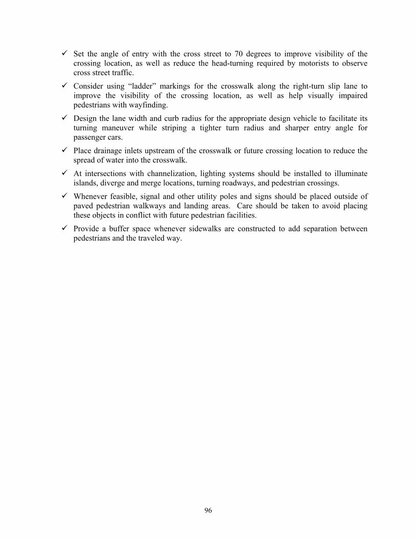
96
Set the angle of entry with the cross street to 70 degrees to improve visibility of the crossing location, as well as reduce the head-turning required by motorists to observe cross street traffic.
Consider using “ladder” markings for the crosswalk along the right-turn slip lane to improve the visibility of the crossing location, as well as help visually impaired pedestrians with wayfinding.
Design the lane width and curb radius for the appropriate design vehicle to facilitate its turning maneuver while striping a tighter turn radius and sharper entry angle for passenger cars.
Place drainage inlets upstream of the crosswalk or future crossing location to reduce the spread of water into the crosswalk.
At intersections with channelization, lighting systems should be installed to illuminate islands, diverge and merge locations, turning roadways, and pedestrian crossings.
Whenever feasible, signal and other utility poles and signs should be placed outside of paved pedestrian walkways and landing areas. Care should be taken to avoid placing these objects in conflict with future pedestrian facilities.
Provide a buffer space whenever sidewalks are constructed to add separation between pedestrians and the traveled way.
97
5. Conclusion
The development of design guidelines and standard drawings for TxDOT involved reviewing applicable literature and soliciting feedback from agency personnel. A number of subject areas examined during the research process raised issues deserving further investigation. The following sections provide a summary of conclusions and recommendations resulting from the project, along with identification of potential topics of future research.
5.1. Conclusions and Recommendations Right-turn slip lanes provide numerous benefits, including a reduction in vehicular delay at intersections by separating through from right-turning traffic, and reducing the continuous crossing distance for pedestrians using a channelizing island. However, the literature indicates that conventional right-turn slip lane designs can be problematic for pedestrians, as their geometric design generally prioritizes the needs of motorists over the needs of other, non-motorized modes.
Consequently, the goal of this research project was to review state-of-the-practice guidance on right-turn slip lanes and produce design guidelines for slip lanes that cater to the needs of different intersection users. The process began with a review of the available literature on right-turn slip lane design and operation. The research team then held focus group meetings with TxDOT representatives to discuss the various design elements that emerged from the literature synthesis. One key take-away from the focus group meetings was the importance of addressing issues at existing facilities in order to improve their safety conditions, particularly for pedestrians. A subsequent focus group meeting was held in solicit feedback on the research team’s findings on retrofitting treatments. The information gathered from the literature review and focus group meetings served as the foundation for the proposed design guidance and proposed retrofitting treatments enclosed in Appendix A of this report.
The new construction design guidance targets urban, suburban, and rural roadways in accordance with the format of TxDOT’s Roadway Design Manual. The urban and suburban design is based on the City of Ottawa “urban smart channel” design, as focus group participants agreed that this design succeeds in catering to pedestrian needs without unduly impacting mobility. In fact, the design benefits motorists as well. It provides a large enough curb radius and paved area to facilitate the turning movement of larger vehicles while delineating a narrower path for passenger vehicles to promote lower turn speeds. The channelizing island and striped pathway are aligned in such a way that the turning roadway intersects the cross street at a sharp angle and, as such, does not require excessive head turning on behalf of the motorists to search for gaps in oncoming traffic.
The crosswalk is recommended to be located in the center of the turning roadway to separate the crossing from the downstream merge point and improve its visibility. This location also accommodates vehicle storage between the crosswalk and the cross street. It was also found in the literature that placement of the crosswalk at the center was the most common practice among state and local highway agencies. The research team also recommends the ladder pattern for crosswalk markings as transverse markings are found to assist pedestrians with vision impairments with wayfinding, and longitudinal markings improve motorist visibility of the
98
crosswalk. A 5-foot-wide bike lane is accommodated in the design using the appropriate pavement markings for an intersection approach.
With regards to auxiliary lanes, the guidance on urban and suburban right-turn slip lane design supports the use of deceleration lanes to allow motorists to slow down before negotiating the turn and help pedestrians identify vehicles intending to enter the slip lane. The guidelines discourage the use of acceleration lanes at these intersections where pedestrian activity is anticipated. The literature suggests that acceleration lanes tend to be problematic at right-turn slip lane locations since they place the pedestrian crossing where higher speed turns are facilitated by the design.
With respect to guidance on pole placement and signage, the guidelines defer to the TMUTCD and other TxDOT standard drawings for guidance. Drainage inlets should be installed upstream of crosswalk locations, and roadway and roadside drainage should be facilitated without impeding pedestrian travel to the extent practical. The guidelines recommend installing all objects and drainage features outside of pedestrian walkways. Further, it is recommended to avoid placing these elements where future pedestrian facilities may be installed.
The rural design guidance mainly centers on facilitating mobility through the slip lane, as regular pedestrian activity is not typical at rural intersections. Accordingly, the design promotes larger sweeping turns, the use of acceleration lanes, unpaved channelizing islands, and a flatter angle of entry into the cross street. In the event that pedestrian activity increases in the future, these intersections can be retrofitted to accommodate area development and travel behavior.
Through the research process, it was determined that the issue of retrofitting existing right-turn slip lanes to improve their safety conditions and make them more accommodating to pedestrians and bicyclists was important. Accordingly, the design guidelines include a section on retrofitting treatments, targeted at issues commonly found at right-turn slip lanes: absence of proper refuge for pedestrians, motorist noncompliance with yielding to crossing pedestrians, pedestrian noncompliance with the crosswalk location, high speeds in the channelized roadway, low visibility of crossing pedestrians, and excessive head turning to spot oncoming traffic. Appendix A includes a compilation of retrofitting treatments TxDOT representatives agreed could alleviate some of the issues encountered at existing right-turn slip lanes.
5.2. Future Research The literature review and focus group meetings carried out as part of Project Tasks 1 and 2, respectively, gave the research team the background and insight that were crucial in developing the design guidance for the application of right-turn slip lanes in Texas. Another byproduct of the effort was the identification of potential topics of future research:
1. NCHRP Report 562 provides thresholds on pedestrian activity and other guidance used to justify installation of pedestrian crossing treatments. To supplement those findings, the City of Boulder, Colorado has devised modified thresholds and additional input regarding their decision process used to justify supplemental crossing treatments. Accordingly, one possible subject of future research could focus on applicable pedestrian activity thresholds for the state of Texas. Specifically, future research can be used to investigate the distinction between ‘high’ and ‘low’ pedestrian activity used in consideration of additional crossing treatments, including pavement markings, signage, and pedestrian activated devices. This research effort may be expanded to include rural areas.
99
2. Existing design guidelines do not generally support the use of acceleration lanes at urban and suburban right-turn slip lane locations. The use of these lanes can have a negative impact on conditions at upstream pedestrians crossings. Hence, future research can be used to help identify under what conditions it is appropriate to use acceleration lanes in urban and suburban areas and how the design may be modified, especially with respect to pedestrian activity and bicycle lane markings along the acceleration lane.
3. The implemented bicycle accommodations at the intersection include a 5-foot-wide bike lane, where applicable. Further research can investigate the provision of bike boxes at intersections where right-turn slip lanes exist and their effect on traffic operations. In addition, other bike lane designs and configurations, including the use of colored pavement or painted bike lanes at locations where motor vehicles and bicycles cross paths, could be reviewed.
4. One of the retrofitting measures proposes restriping an existing right-turn slip lane in order to delineate a narrower path for smaller vehicles. Further research can study the feasibility and effectiveness of such a retrofitting measure in terms of safety and traffic operations of the slip lane.
5. NCHRP Report 674 provides potential crossing treatments for roundabouts and channelized turn lanes for pedestrians with vision disabilities. Further research can follow up on this effort and identify findings applicable to the state of Texas. Hence, the proposed design solutions can be further modified to reflect the latest findings in this field.
6. Currently, the City of Ottawa has not published a report on the effectiveness of the “urban smart channel” design. Further research can study the effectiveness of the proposed design, as well as retrofitting strategies after implementation. A comparative study can be done using new design installations. Moreover, a before-after study can be performed on retrofitted right-turn slip lanes in order to determine the effectiveness of the proposed treatments.

100
101
References
AASHTO (2004). Guide for the Planning, Design and Operation of Pedestrian Facilities. Washington, D.C.: American Association of State Highway and Transportation Officials.
AASHTO (2011). A Policy on Geometric Design of Highways and Streets. Washington, D.C.
AASHTO (2012). Guide for the Development of Bicycle Facilities. Washington, D.C.: American Association of State Highway and Transportation Officials.
Americans with Disabilities Act (2010, September 15). 2010 ADA Standards for Accesible Design. Retrieved from Americans with Disabilities Act: http://www.ada.gov/regs2010/2010ADAStandards/2010ADAStandards_prt.pdf
Architectural and Transportation Barriers Compliance Board (2005). Revised Draft Guidelines for Accessible Public Rights-of-Way. United States Access Board. Retrieved from http://www.access-board.gov/guidelines-and-standards/streets-sidewalks/public-rights-of-way/background/revised-draft-guidelines/chapter-3
Chandler, B. E., Myers, M. C., Atkinson, J. E., Bryer, T. E., Retting, R., Smithline, J., . . . Malone, B. J. (2013). Signalized Intersections Informational Guide Second Edition. Washington, D.C.: Federal Highway Administration. Retrieved from http://safety.fhwa.dot.gov/intersection/signalized/13027/fhwasa13027.pdf
Chang, D. (2008). National Pedestrian Crash Report. Washington, D.C.: National Highway Traffic Safety Administration. Retrieved from http://www-nrd.nhtsa.dot.gov/Pubs/810968.pdf
City of Ottawa (2010). Pedestrian Intersection Safety Countermeasure Handbook. Ottawa: City of Ottawa.
Dixon, K. K., Hibbard, J. L., & Nyman, H. (1999). Right-Turn Treatment for Signalized Intersections. Transportation Research Circular E-C019.
Federal Highway Administration (2001). The Controlling Criteria. In FHWA's Mitigation Strategies for Design Exceptions. U.S. Department of Transportation. Retrieved from http://safety.fhwa.dot.gov/geometric/pubs/mitigationstrategies/chapter3/3_lanewidth.htm
Federal Highway Administration (2012). Manual on Uniform Traffic Control Devices. Federal Highway Administration. Washington, D.C.: US Department of Transportation. Retrieved from http://ftp.dot.state.tx.us/pub/txdot-info/trf/tmutcd/2011_rev1/revision_1.pdf
FDOT (2014). Standard "17346 ‐ Special Marking Areas." FDOT Design Standards.
Fitzpatrick, K., & Schneider, W. H. (2005). Turn Speeds and Crashes Within Right-Turn Lanes. Federal Highway Administration. Retrieved from http://tti.tamu.edu/documents/0-4365-4.pdf
Fitzpatrick, K., Turner, S., Brewer, M., Carlson, P., Ullman, B., Trout, N., . . . Lord, D. (2006). TCRP Report 112/NCHRP Report 562: Improving Pedestrian Safety at Unsignalized Intersections. Washington, D.C.: Transportation Research Board of the National Academies.
Fox Tuttle (2011) City of Boulder Pedestrian Crossing Treatment Installation Guidelines, Transportation Division, City of Boulder, CO.
Google Maps (2014).
102
Harwood, D. W., Council, F. M., Hauer, E., Hughes, W. E., & Vogt, A. (2000). Prediction of the Expected Safety Performance of Rural Two-Lane Highways. Kansas City: Federal Highway Administration. Retrieved from http://www.fhwa.dot.gov/publications/research/safety/99207/99207.pdf
Henson, C. A. (2009). Signing, Pavement Marking, Signalization and Lighting. Retrieved from Florida Department of Transportation: http://www.dot.state.fl.us/rddesign/Training/Webinar09/TrafficDesign.pdf
Hondrop, B., Ryan, S., Corbett, S., Enderle, B., Jovanovic, S., Abboud, N., & Smith, C. (2010). City of Chula Vista Pedestrian Master Plan. Chula Vista: City of Chula Vista.
Hughes, R., Huang, H., Zeeger, C., & Cynecki, M. (2001). Evaluation of Automated Pedestrian Detection at Signalized Intersections. Federal Highway Administrations. Retrieved from http://www.fhwa.dot.gov/publications/research/safety/00097/00097.pdf
Institute of Transportation Engineers (2006). Context Sensitive Solutions in Designing Major Urban Thoroughfares for Walkable Communities. Washington, D.C.: Institute of Transportation Engineers. Retrieved from http://www.ite.org/bookstore/RP036.pdf
King, M. (2002). Bicycle Facility Selection: A Comparison of Approaches. Highway Safety Research Center. University of North Carolina. Retrieved from http://www.hsrc.unc.edu/pdf/2002/BicycleFacilitySelectionMKingetal2002.pdf
Maryland State Highway Administration (n.d.). Bicycle and Pedestrian Design Guidelines. Maryland Department of Transportation.
McCoy, P. T., & Bonneson, J. A. (1996). Volume Warrant for Free Right-Turn Lanes at Unsignalized Intersections on Rural Two-Lane Highways. Transportation Research Record 1523. Transportation Research Board.
McCoy, P. T., Bishu, R., Bonneson, J. A., Fitts, J. W., Fowler, M. D., Gaber, S. L., . . . Sicking, D. L. (1995). Guidelines for Free Right-Turn Lanes at Unsignalized Intersections on Rural Two-Lane Highways. University of Nebraska-Lincoln, Nebraska. Department of Roads.
McCoy, P. T., Bonneson, J. A., Ataullah, S., & Eitel, D. S. (1994). Guidelines for Right-Turn Lanes on Urban Roadways. Transportation Research Record (pp. 130-137). Transportation Research Board.
Milestones 8(3) (2008). “A Real Head Turner: Urban Smart Channels Debut in Ottawa”, Ontario Good Roads Association, Oakville, Ontario, pp. 49-51, 2008.
Miller, S. (2014, May 16). In Harlem, Bradhurst Plaza Supporters Struggle to Change Status Quo. Retrieved from Streets Blog NYC: http://www.streetsblog.org/2014/05/16/bradhurst-plaza-supporters-struggle-at-cb-10-against-die-hard-opponents/
Nabti, J. M., & Ridgeway, M. D. (2002). Innovative Bicycle Treatments: An Informational Report of the Institute of Transportation Engineers (ITE) and the ITE Pedestrian and Bicycle Council. Washington, D.C.: Institute of Transportation Engineers.
Perez, R. A. (1995, February). Guidelines for Right-Turn Treatments at Signalized Intersections. ITE Journal (23). Retrieved from http://citeseerx.ist.psu.edu/viewdoc/download?doi=10.1.1.417.2769&rep=rep1&type=pdf
Pietrucha, M. T., & Opiela, K. S. (1993). Safe Accommodation of Pedestrians at Intersections. Transportation Research Record, 1385.
103
Potts, I. B., Harwood, D. W., Torbic, D. J., & Gilmore, D. K. (2006a). NCHRP 3-72: Synthesis on Lane Widths on Urban and Suburban Arterials. Midwest Research Institute. Kansas City: National Cooperative Highway Research Program.
Potts, I. B., Harwood, D. W., Torbic, D. J., & Gilmore, D. K. (2006b). NCHRP 3-72: Synthesis on Right-Turn Deceleration Lanes on Urban and Suburban Arterials. Midwest Research Institute. Kansas City: National Cooperative Highway Research Program.
Potts, I. B., Ringert, J. F., Bauer, K. M., Zeeger, J. D., Harwood, D. W., & Gilmore, D. K. (2006c). Relationship of Lane Width to Saturation Flow Rate on Urban and Suburban Signalized Intersection Approaches. Transportation Research Record, 2027. doi:10.3141/2027-06
Potts, I. B., Tiesler, C. B., & Torbic, D. J. (2006d). NCHRP 3-72: Synthesis on Channelized Right Turns at Intersections. Midwest Research Institute. Kansas City: National Cooperative Highway Research Program.
Potts et al. (2011). NCHRP 3-89: Design Guidance for Channelized Right-Turn Lanes. Midwest Research Institute. Kansas City: National Cooperative Highway Research Program.
Road Crossings Green (2011, November 25). Retrieved from Community Remarks: http://www.communityremarks.com/Ferndale//kml/RoadCrossingsGreen232014.kml
Rodegerdts, L. A., Robinson, B., Nevers, B., Ringert, J., Koonce, P., Bansen, J., . . . Courage, K. (2004). Signalized Intersections: Informational Guide. Federal Highway Administration. Retrieved from http://www.fhwa.dot.gov/publications/research/safety/04091/04091.pdf
Schnell, T., Neyens, D. M., Lee, Y.-C., & Aktan, F. (2004). How to More Safely Accommodate Pedestrians through an Intersection with Free-Flow Legs. St Paul: Minnesota Department of Transportation. Retrieved from http://www.lrrb.org/media/reports/200424.pdf
Schroeder, B. J. (2007). NCHRP 03-78 Update: Crossing Solutions for Pedestrians with Vision Impairments at Roundabouts and Channelized Right Turn Lanes. Institute for Transportation Engineers. Pittsburgh: Institute for Transportation Research and Education (ITRE).
Schroeder, B., Hughes, R., Cunningham, C., Salamati, K., Long, R., Guth, D., . . . Myers, E. (2011). NCHRP Report 674: Crossing Solutions at Roundabouts and Channelized Turn Lanes for Pedestrians with Vision Disabilities. Washington, D.C.: Transportation Research Board of the National Academies.
Schroeder, B., Hughes, R., Rouphail, N., Cunnigham, C., & Salamati, K. (2010). NCHRP Web-Only Document 160: Supporting Material to NCHRP Report 674. Washington, D.C.: Transportation Research Board of the National Academies.
Tarawneh, M. S., & McCoy, P. T. (1996). Effect of Intersection Channelization and Skew on Driver Performance. Transportation Research Record 1523.
The City and County of San Francisco. (2011). Better Streets San Francisco. Retrieved from http://www.sf-planning.org/ftp/BetterStreets/docs/Draft_BSP_5_Street_Designs.pdf
Toole Design Group. (2009). Walk Wilmington: A Comprehensive Pedestrian Plan. City of Wilmington, North Carolina.
Tuttle, S. (2003). City of Boulder Crosswalk Compliance Studies & Treatment Implementation. Pedestrian and Bicycle Information Center. Retrieved from http://katana.hsrc.unc.edu/cms/downloads/ENG.CityofBoulderCrosswalkComplianceStudies.pdf
104
TxDOT (2002). Standard PED-12A.
TxDOT (2007-2012). TxDOT Cris Files.
TxDOT (2011). Access Management Manual. Texas Department of Transportation.
TxDOT (2012a). Standard "Ped-12A Pedestrian Facilities, Curb Ramps.” TxDOT Design Division Standards.
TxDOT (2012b). Texas Manual on Uniform Traffic Control Devices, Revision 1. Texas Department of Transportation.
TxDOT (2013). Roadway Design Manual. Texas Department of Transportation.
Umbs, R. (2010). Raised Right Turn Islands. Federal Highway Administration. Retrieved from http://www.d7ctst.org/Right%20Turn%20Islands.pdf
University of North Carolina (1999). Florida Pedestrian and Planning Handbook. Florida Department of Transportation. Retrieved from http://safety.fhwa.dot.gov/intersection/resources/fhwasa09027/resources/Florida%20Pedestrian%20Facilities%20Planning%20and%20Design%20Handbook.pdf
Zeeger, C. V., Opiela, K. S., & Cynecki, M. J. (1985). Pedestrian Signalization Alternatives. Federal Highway Administration.
Zeeger, C., Cynecki, M., Lagerwey, P., Fegan, J., Tan, C., Gilleran, B., & Works, B. (1994). FHWA Study Tour for Pedestrian and Bicyclist Safety in England, Germany, and the Netherlands. US Department of Transportation, Federal Highway Administration, Baltimore. Retrieved from http://ntl.bts.gov/DOCS/bikeped.html
Zeeger, C., Nabors, D., & Lagerwey, P. (2013, August). Pedestrian Safety Guide and Countermeasure Selection System. Federal Highway Administration. Retrieved from PEDSAFE: http://www.pedbikesafe.org/PEDSAFE/countermeasures_detail.cfm?CM_NUM=24
Zeeger, C., Seiderman, C., Lagerwey, P., Cynecki, M., Ronkin, M., & Schneider, R. (2002). Pedestrian Facilities Users Guide. US Department of Transportation, Federal Highway Administration. McLean: Federal Highway Administration. Retrieved from http://katana.hsrc.unc.edu/cms/downloads/PedFacility_UserGuide2002.pdf
Zeeger, J. D. (1986). Field Validation of Intersection Capacity Factors. Transportation Research Record 1091. Transportation Research Board.

105
Appendix A
This appendix provides design guidelines for right-turn slip lanes, intended to be added to the TxDOT Roadway Design Manual as “Appendix D — Right-Turn Slip Lane Design Guidelines.”
Appendix D — Right-Turn Slip Lane Design Guidelines
Roadway Design Manual D-1 TxDOT 10/2014
Appendix D — Right-Turn Slip Lane Design Guidelines
Contents:
Section 1 — Purpose
Section 2 — Introduction
Section 3 — New Construction
Section 4 — Retrofitting Treatments
Section 5 — References
Appendix D — Right-Turn Slip Lane Design Guidelines
Roadway Design Manual D-2 TxDOT 10/2014
Section 1 — Purpose
The purpose of this Appendix is to provide guidance on the design of right-turn slip lanes, including lane and raised island geometric layouts, striping guidelines, pedestrian and bikeway guidelines, and accommodations for pedestrians with disabilities. Since their design is dictated by multiple criteria (operating speed, design vehicle, future traffic volumes, etc.), guidance is provided for different roadway environments: urban, suburban, and rural. At existing intersections where right-turn slip lanes have already been installed, treatment options for retrofitting are also provided to alleviate common issues identified at such locations.
Appendix D — Right-Turn Slip Lane Design Guidelines
Roadway Design Manual D-3 TxDOT 10/2014
Section 2 — Introduction
Right‐turn slip lanes are advantageous to motorists as they reduce delays by separating right-turning traffic from adjacent lanes and accommodating higher‐speed right turns. The right-turn slip lane channelizing island can provide a refuge area for crossing pedestrians, reducing their exposure by allowing them to cross the roadway in two stages. However, right‐turn slip lanes may encourage higher-than-intended vehicular speeds and create conflicts among motor traffic, pedestrians, and bicyclists. Accordingly, right-turn slip lane designs should create a balance between the safety and mobility of all roadway users. The subsequent sections address new right-turn slip lane construction on urban, suburban, and rural roads as well as retrofitting treatments for existing intersections.
Appendix D — Right-Turn Slip Lane Design Guidelines
Roadway Design Manual D-4 TxDOT 10/2014
Section 3 — New Construction Urban Design
Urban streets are roadways in developed areas where there can be pedestrians, motor traffic, and bicyclists travelling within the same corridor. Right-turn slip lanes at urban intersections shall be designed to accommodate both pedestrians and motorists, with special consideration for crosswalk compliance (on behalf of both motorists and pedestrians), design vehicle accommodations, speed of turning traffic, provision of auxiliary lanes, adjacent land uses, anticipated pedestrian traffic, and visibility of the crossing location(s).
The following recommendations address these considerations, providing design guidance for right-turn slip lanes that not only caters to the needs of motorists, but also provides safer accommodations for pedestrians and bicyclists. Please refer to Figures D-6 and D-7 at the end of the section for illustrations.
1. Angle of Entry: The angle of entry between the slip lane and the cross street is recommended to be 70 degrees. This configuration slows motorists and does not require them to turn their head to the left as much to look for gaps in oncoming traffic. It is also easier for motorists to identify crossing pedestrians because the crossing location is in the direct line of sight for turning motorists. If an angle of 70 degrees is not achievable due to right-of-way or other restrictions, the minimum recommended angle is 55 degrees.
2. Curb Radius and Lane Width: The majority of traffic on urban streets is expected to be passenger cars and single unit trucks. However, to accommodate the turning movement of larger vehicles, the curb radius and lane width can be designed for a larger design vehicle while striped to delineate the path for smaller vehicles. For guidance on radius design for different vehicle classes, see the discussion in Chapter 3 on Intersections and the Urban Intersections subsection in Minimum Designs for Truck and Bus Turns in Chapter 7.
3. Channelizing Island: To provide adequate pedestrian refuge, channelizing islands should be raised with a recommended minimum size of 100 ft2 [9.3 m2]. Islands are recommended to have a side length of 15 ft [4.5 m] (12 ft [3.6 m] minimum), excluding the corner radii as discussed in AASHTO’s A Policy on the Geometric Design of Highways and Streets. Channelizing islands should be offset from the edge of the traveled way to reduce their vulnerability. In the presence of a bike lane, which serves as a separation between the curb and the travel lane, curbs need not be offset. See Chapter 9 of AASHTO’s A Policy on Geometric Design of Highways and Streets for design guidance on curb offset and tapering (Figure D-1). Additional information on appropriate curb type and design can be found in Basic Design Criteria, Chapter 2 and TxDOT standard drawings for curb and gutter. Details on island approach treatment and delineation are presented in Chapter 3 of the Texas Manual on Uniform Traffic Control Devices (TMUTCD) and Chapter 9 of AASHTO’s A Policy on Geometric Design of Highways and Streets.
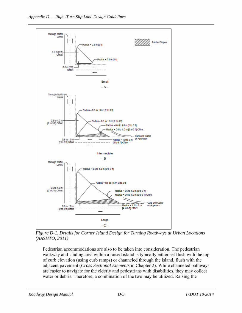
Appendix D — Right-Turn Slip Lane Design Guidelines
Roadway Design Manual D-5 TxDOT 10/2014
Figure D-1. Details for Corner Island Design for Turning Roadways at Urban Locations (AASHTO, 2011)
Pedestrian accommodations are also to be taken into consideration. The pedestrian walkway and landing area within a raised island is typically either set flush with the top of curb elevation (using curb ramps) or channeled through the island, flush with the adjacent pavement (Cross Sectional Elements in Chapter 2). While channeled pathways are easier to navigate for the elderly and pedestrians with disabilities, they may collect water or debris. Therefore, a combination of the two may be utilized. Raising the
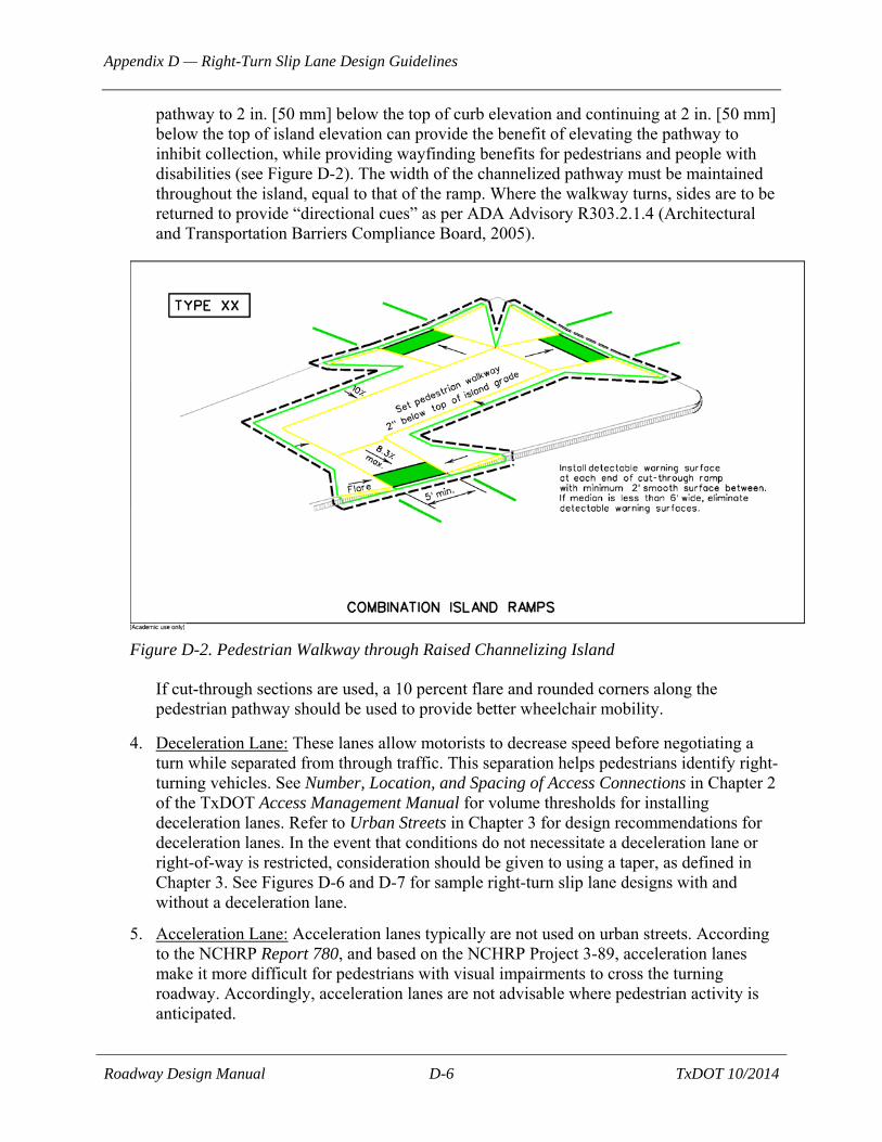
Appendix D — Right-Turn Slip Lane Design Guidelines
Roadway Design Manual D-6 TxDOT 10/2014
pathway to 2 in. [50 mm] below the top of curb elevation and continuing at 2 in. [50 mm] below the top of island elevation can provide the benefit of elevating the pathway to inhibit collection, while providing wayfinding benefits for pedestrians and people with disabilities (see Figure D-2). The width of the channelized pathway must be maintained throughout the island, equal to that of the ramp. Where the walkway turns, sides are to be returned to provide “directional cues” as per ADA Advisory R303.2.1.4 (Architectural and Transportation Barriers Compliance Board, 2005).
Figure D-2. Pedestrian Walkway through Raised Channelizing Island
If cut-through sections are used, a 10 percent flare and rounded corners along the pedestrian pathway should be used to provide better wheelchair mobility.
4. Deceleration Lane: These lanes allow motorists to decrease speed before negotiating a turn while separated from through traffic. This separation helps pedestrians identify right-turning vehicles. See Number, Location, and Spacing of Access Connections in Chapter 2 of the TxDOT Access Management Manual for volume thresholds for installing deceleration lanes. Refer to Urban Streets in Chapter 3 for design recommendations for deceleration lanes. In the event that conditions do not necessitate a deceleration lane or right-of-way is restricted, consideration should be given to using a taper, as defined in Chapter 3. See Figures D-6 and D-7 for sample right-turn slip lane designs with and without a deceleration lane.
5. Acceleration Lane: Acceleration lanes typically are not used on urban streets. According to the NCHRP Report 780, and based on the NCHRP Project 3-89, acceleration lanes make it more difficult for pedestrians with visual impairments to cross the turning roadway. Accordingly, acceleration lanes are not advisable where pedestrian activity is anticipated.
Appendix D — Right-Turn Slip Lane Design Guidelines
Roadway Design Manual D-7 TxDOT 10/2014
6. Drainage: Drainage should be accommodated along the turning roadway. Inlets should be designed and placed on the upstream side of the crosswalk at a location that prevents, or limits to the extent practical, the spread of water into the crosswalk. Cut-through access should be provided to minimize paths for water flow. The right-turn lane should be sloped in order to facilitate proper drainage.
7. Lighting: As discussed in AASHTO’s A Policy on the Geometric Design of Highways and Streets, intersections with channelization should be illuminated. Lighting helps motorists identify islands, diverge and merge locations, turning roadways, and pedestrian crossings enabling them to reduce speed and navigate appropriately. Adequate lighting at urban intersections, including illumination of crossing locations, is important, particularly where pedestrian activity is expected at night. Additional information on intersection and pedestrian facilities lighting can be found in AASHTO’s A Policy on the Geometric Design of Highways and Streets and Guide for the Planning, Design, and Operation of Pedestrian Facilities. See TxDOT standard drawings for illumination details.
8. Pole Placement: Signal and other utility poles should be outside of paved pedestrian walkways and landing areas. Refer to the TMUTCD and TxDOT standard drawings for guidance on mounting height, limits on object protrusion into the pedestrian space, and pedestrian facilities placement, including pedestrian detectors. When pedestrian facilities are not installed, care should be taken when placing poles to avoid the anticipated or planned location of future pedestrian walkways and landing areas. As such, consideration should be given to determine where these facilities may be installed in the future to avoid conflicts and a need to relocate utilities or implement costly retrofitting treatments.
9. Crosswalk Location: Crosswalks should be placed in the middle of the turning roadway, or as close to the center as feasible. Crosswalks may be placed near the beginning of the turning roadway if conditions do not permit a centralized location or it is more conducive to the natural pathway of pedestrians. When the crossing is located at the beginning of the turning roadway, care should be taken to place it such that there is enough space available at the ramp location in the channelizing island for an appropriate landing area. Placement of the crosswalk near the end of the turning roadway is not recommended as motorists are expected to encroach on the crosswalk as they yield to oncoming traffic. Also, motorists arriving at the downstream end of the turning roadway typically focus their attention on cross street traffic rather than on crossing pedestrians.
10. Crosswalk Orientation: The pedestrian crosswalk should be oriented perpendicular to the turning roadway to shorten the crossing distance for pedestrians and place approaching vehicles in their periphery.
11. Crosswalk Markings: At locations where pedestrian activity is anticipated, “ladder” markings are recommended to delineate the crossing location. Transverse markings help facilitate wayfinding for visually impaired pedestrians and inclusion of longitudinal lines provides additional visibility for approaching motorists. If the need for ladder markings cannot be established, transverse markings can be installed to define the crossing path. Refer to the TMUTCD for guidance on the installation of crosswalk markings. At locations with little to no pedestrian activity and where their crossing may not be expected by drivers, thereby placing driver compliance in question, consideration may be
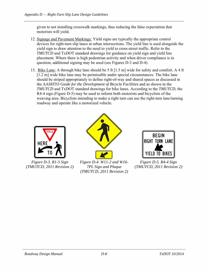
Appendix D — Right-Turn Slip Lane Design Guidelines
Roadway Design Manual D-8 TxDOT 10/2014
given to not installing crosswalk markings, thus reducing the false expectation that motorists will yield.
12. Signage and Pavement Markings: Yield signs are typically the appropriate control devices for right-turn slip lanes at urban intersections. The yield line is used alongside the yield sign to draw attention to the need to yield to cross-street traffic. Refer to the TMUTCD and TxDOT standard drawings for guidance on yield sign and yield line placement. Where there is high pedestrian activity and when driver compliance is in question, additional signing may be used (see Figures D-3 and D-4).
13. Bike Lane: A through bike lane should be 5 ft [1.5 m] wide for safety and comfort. A 4 ft [1.2 m] wide bike lane may be permissible under special circumstances. The bike lane should be striped appropriately to define right-of-way and shared spaces as discussed in the AASHTO Guide for the Development of Bicycle Facilities and as shown in the TMUTCD and TxDOT standard drawings for bike lanes. According to the TMUTCD, the R4-4 sign (Figure D-5) may be used to inform both motorists and bicyclists of the weaving area. Bicyclists intending to make a right turn can use the right-turn lane/turning roadway and operate like a motorized vehicle.
Figure D-3. R1-5 Sign
(TMUTCD, 2011 Revision 2) Figure D-4. W11-2 and W16-
7PL Sign and Plaque (TMUTCD, 2011 Revision 2)
Figure D-5. R4-4 Sign (TMUTCD, 2011 Revision 2)
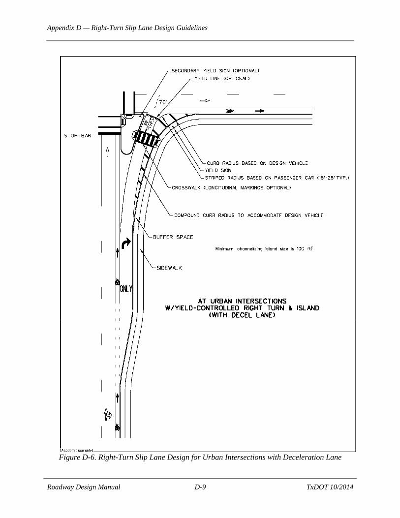
Appendix D — Right-Turn Slip Lane Design Guidelines
Roadway Design Manual D-9 TxDOT 10/2014
Figure D-6. Right-Turn Slip Lane Design for Urban Intersections with Deceleration Lane
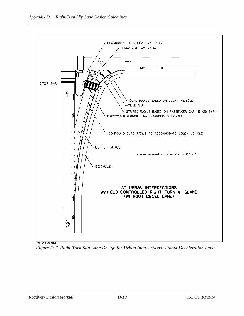
Appendix D — Right-Turn Slip Lane Design Guidelines
Roadway Design Manual D-10 TxDOT 10/2014
Figure D-7. Right-Turn Slip Lane Design for Urban Intersections without Deceleration Lane
Appendix D — Right-Turn Slip Lane Design Guidelines
Roadway Design Manual D-11 TxDOT 10/2014
Suburban Design
Suburban roadways are high-speed facilities that provide a transition between urban and rural roadways. Pedestrian activity on these roadways is expected to be in the range of light to moderate. Accordingly, right-turn slip lane design for suburban roadways should accommodate pedestrians while not severely impacting traffic flow. The following recommendations address the presence of pedestrians and facilitate potential future retrofits without heavily impacting mobility.
1. Angle of Entry: For guidance on angle of entry for suburban roadways, see Urban Design, Angle of Entry.
2. Curb Radius and Lane Width: The radius and lane width for right-turning roadways in suburban areas should be designed to accommodate high-speed turns and larger design vehicles. In the event that the area becomes more urbanized in the future, the turning roadway can be striped to delineate a tighter radius, promoting lower speeds and improving visibility of pedestrians for motorists (see Figures D-6 and D-7). See Cross Sectional Elements in Chapter 2 for recommendations on lane width.
3. Channelizing Island: For guidance on channelizing island design for suburban roadways, see Urban Design, Channelizing Island.
4. Deceleration Lane: For guidance on deceleration lanes for suburban roadways, see Urban Design, Deceleration Lane.
5. Acceleration Lane: There is no specific recommendation in this manual for using acceleration lanes on suburban roadways. However, the Chapter 3 section Suburban Roadways refers to the Urban Streets section for recommendations about speed change lanes. According to NCHRP Report 780, and based on guidance from NCHRP Project 3-89, acceleration lanes make it more difficult for pedestrians with visual impairments to cross the turning roadway. Accordingly, acceleration lanes are not advisable where pedestrian activity is anticipated.
6. Drainage: For guidance on drainage for suburban roadways, see Urban Design, Drainage. When pedestrian facilities are not installed, consideration should be given to determine where crosswalks may be installed in the future to avoid conflicts with inlet locations.
7. Lighting: For guidance on lighting for suburban roadways, see Urban Design, Lighting.
8. Pole Placement: For guidance on pole placement for suburban roadways, see Urban Design, Pole Placement. When pedestrian facilities are not installed, care should be taken when placing poles to avoid the anticipated or planned location of future pedestrian walkways and landing areas. As such, consideration should be given to determine where these facilities may be installed in the future to avoid conflicts and a need for relocating utilities or implementing costly retrofitting treatments.
9. Crosswalk Location: Crosswalks should be placed in the middle of the turning roadway, or as close to the center as feasible. Crosswalks may be placed near the beginning of the turning roadway if conditions do not permit a centralized location or it is more conducive to the natural pathway of pedestrians. When the crossing is located at the beginning of the
Appendix D — Right-Turn Slip Lane Design Guidelines
Roadway Design Manual D-12 TxDOT 10/2014
turning roadway, care should be taken to place it such that there is enough space available at the ramp location in the channelizing island for an appropriate landing area. Placement of the crosswalk near the end of the turning roadway is not recommended as motorists are expected to encroach on the crosswalk as they yield to oncoming traffic. Accordingly, ramps should be installed at the crosswalk in compliance with the ADA. In the event that an acceleration lane is present, consider placing the crosswalk at the upstream end of the turning roadway. This places pedestrians in the line of sight for drivers as they decelerate to make the turn, rather than introducing a crossing where they will be accelerating out of the turn and more likely focusing on cross street traffic.
10. Crosswalk Orientation: The pedestrian crosswalk should be oriented perpendicular to the turning roadway to shorten the crossing distance for pedestrians and place approaching vehicles in their periphery.
11. Crosswalk Markings: At locations where pedestrian activity is anticipated, see Urban Design, Crosswalk Markings. At locations with little to no pedestrian activity and where their crossing may not be expected by drivers, thereby placing driver compliance in question, consideration may be made to not install crosswalk markings thus reducing the false expectation that motorists will yield. At locations with adjacent sidewalks, ramps should be installed at the time of construction, regardless of striping, to facilitate crossings and future retrofits of the intersection if pedestrian activity increases.
12. Signage: For guidance on signage for suburban roadways, see Urban Design, Signage.
13. Bike Lane: For guidance on bike lanes for suburban roadways, see Urban Design, Bike Lane.
Rural Design
In general, rural areas are expected to have higher speeds and little to no pedestrian activity. As such, designing right-turn slip lanes for better mobility of traffic is a priority. In rural areas, where pedestrian crossings are not expected by motorists, provision of crossing treatments may provide pedestrians with a false sense of security; when no pedestrian activity is anticipated and no facilities are installed at the intersection, no crossing treatments are recommended. Where pedestrian activity is anticipated, the turning roadway should be designed to provide adequate visibility for pedestrians. In addition to providing visibility of the crossing location, pedestrians should have appropriate sight distance for identifying oncoming vehicles to accommodate their decision to wait for the vehicle(s) to pass or cross the turning roadway safely. If pedestrian activity is expected, the guidelines for suburban roadways can generally be referenced. Provisions for future crossing treatments should include placing signal and/or utility poles, drainage inlets, and other obstructions outside the expected extent of future pedestrian walkways and landing areas.
1. Angle of Entry: In rural areas, the angle of entry between the slip lane and the cross street is typically flatter than in urban areas to facilitate high-speed turns; lower angles are especially practical when the turning roadway feeds directly into an acceleration lane. In the absence of an acceleration lane, the angle of entry should be as close to 70 degrees as feasible, particularly if pedestrian crossings are anticipated.
Appendix D — Right-Turn Slip Lane Design Guidelines
Roadway Design Manual D-13 TxDOT 10/2014
2. Radius and Lane Width: Given that larger vehicles are expected to traverse rural highways, the curb radius and lane width for right-turning roadways should be designed for a larger design vehicle (40 ft [12 m] to 50 ft [15 m] radius11). For guidance on radius design for different vehicle classes, see discussion in Chapter 3 on Intersections and the Urban Intersections subsection in Minimum Designs for Truck and Bus Turns in Chapter 7. Right-turn slip lanes in rural areas are likely to incorporate large, sweeping turning roadways with superelevation. See Basic Design Criteria in Chapter 2 for the relationship between superelevation and curve radius.
3. Channelizing Island: The minimum recommended size for channelizing islands to provide pedestrian refuge is 100 ft2 [9.3 m2]. Islands are recommended to have a side length of 15 ft [4.5 m] (12 ft [3.6 m] minimum), excluding the corner radii as discussed in AASHTO’s A Policy on the Geometric Design of Highways and Streets. Pedestrian accommodations are to be taken into consideration where pedestrian activity is expected. If the angle of entry is flat, the island should be constructed as an equilateral triangle. In areas with no pedestrian activity, the channelizing island may be flush with the pavement or depressed.
In rural areas, careful consideration should be made for the use of curbed islands, particularly along high-speed facilities and at isolated intersections. If curbs are installed, they should be sloped and offset from the traveled way, and islands made clearly visible to motorists. See Chapter 9 of AASHTO’s A Policy on Geometric Design of Highways and Streets for design guidance on curb offset and tapering (Figure D-1). Additional information on appropriate curb type and design can be found in Basic Design Criteria, Chapter 2 and TxDOT standard drawings for curb and gutter. Details on island approach treatment and delineation are presented in Chapter 3 of the Texas Manual on Uniform Traffic Control Devices (TMUTCD) and Chapter 9 of AASHTO’s A Policy on Geometric Design of Highways and Streets.
4. Deceleration Lane: See Number, Location, and Spacing of Access Connections in Chapter 2 of the TxDOT Access Management Manual for volume thresholds for installing deceleration lanes. See Multi-Lane Rural Highways, Deceleration Lanes in Chapter 3 for design recommendations for deceleration lanes.
5. Acceleration Lane: See Number, Location, and Spacing of Access Connections in Chapter 2 of the TxDOT Access Management Manual for volume thresholds for installing acceleration lanes. These lanes provide a benefit when right-turn volumes are especially high and/or the speed differential between turning vehicles and vehicles on the cross street is large. Acceleration lanes provide benefits to motorist by allowing them to reach a higher speed prior to merging, but may increase sideswipe accidents. Acceleration lanes have been found to be preferred by elderly drivers at high-speed intersection locations. See Two-Lane Rural Highways, Acceleration Lanes and Multi-Lane Rural Highways, Acceleration Lanes in Chapter 3 for design recommendations for acceleration lanes for two-lane and multilane rural highways, respectively.
6. Drainage: Consider the drainage along the turning roadway. In rural areas, curb and gutter systems with inlets are not typically installed. However, in the event that a drainage system is required, inlets should be designed and placed on the upstream side of the crosswalk, if present, at a location that prevents, or limits to the extent practical, the
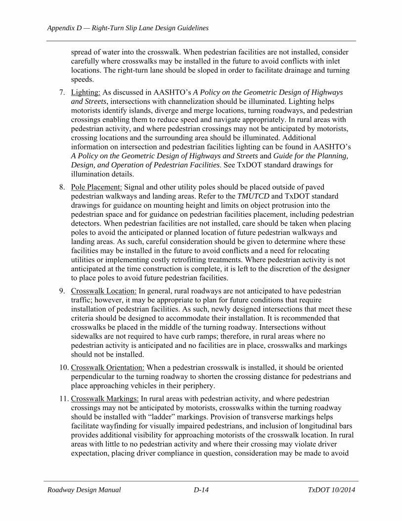
Appendix D — Right-Turn Slip Lane Design Guidelines
Roadway Design Manual D-14 TxDOT 10/2014
spread of water into the crosswalk. When pedestrian facilities are not installed, consider carefully where crosswalks may be installed in the future to avoid conflicts with inlet locations. The right-turn lane should be sloped in order to facilitate drainage and turning speeds.
7. Lighting: As discussed in AASHTO’s A Policy on the Geometric Design of Highways and Streets, intersections with channelization should be illuminated. Lighting helps motorists identify islands, diverge and merge locations, turning roadways, and pedestrian crossings enabling them to reduce speed and navigate appropriately. In rural areas with pedestrian activity, and where pedestrian crossings may not be anticipated by motorists, crossing locations and the surrounding area should be illuminated. Additional information on intersection and pedestrian facilities lighting can be found in AASHTO’s A Policy on the Geometric Design of Highways and Streets and Guide for the Planning, Design, and Operation of Pedestrian Facilities. See TxDOT standard drawings for illumination details.
8. Pole Placement: Signal and other utility poles should be placed outside of paved pedestrian walkways and landing areas. Refer to the TMUTCD and TxDOT standard drawings for guidance on mounting height and limits on object protrusion into the pedestrian space and for guidance on pedestrian facilities placement, including pedestrian detectors. When pedestrian facilities are not installed, care should be taken when placing poles to avoid the anticipated or planned location of future pedestrian walkways and landing areas. As such, careful consideration should be given to determine where these facilities may be installed in the future to avoid conflicts and a need for relocating utilities or implementing costly retrofitting treatments. Where pedestrian activity is not anticipated at the time construction is complete, it is left to the discretion of the designer to place poles to avoid future pedestrian facilities.
9. Crosswalk Location: In general, rural roadways are not anticipated to have pedestrian traffic; however, it may be appropriate to plan for future conditions that require installation of pedestrian facilities. As such, newly designed intersections that meet these criteria should be designed to accommodate their installation. It is recommended that crosswalks be placed in the middle of the turning roadway. Intersections without sidewalks are not required to have curb ramps; therefore, in rural areas where no pedestrian activity is anticipated and no facilities are in place, crosswalks and markings should not be installed.
10. Crosswalk Orientation: When a pedestrian crosswalk is installed, it should be oriented perpendicular to the turning roadway to shorten the crossing distance for pedestrians and place approaching vehicles in their periphery.
11. Crosswalk Markings: In rural areas with pedestrian activity, and where pedestrian crossings may not be anticipated by motorists, crosswalks within the turning roadway should be installed with “ladder” markings. Provision of transverse markings helps facilitate wayfinding for visually impaired pedestrians, and inclusion of longitudinal bars provides additional visibility for approaching motorists of the crosswalk location. In rural areas with little to no pedestrian activity and where their crossing may violate driver expectation, placing driver compliance in question, consideration may be made to avoid
Appendix D — Right-Turn Slip Lane Design Guidelines
Roadway Design Manual D-15 TxDOT 10/2014
installing crosswalk markings, even where ramps are provided, to reduce the false sense of security they may provide pedestrians that motorists will yield to them.
12. Signage: In the presence of a crosswalk, especially one that violates driver expectation, crossing signs (see Figures D-3 and D-4) may be installed to alert motorists of the need to yield to pedestrians.
13. Bike Lane: Bike lanes are not typically installed along rural highways. Paved shoulders along these roadways may be utilized by bicyclists where the width is sufficient to provide a safe accommodation. A minimum paved shoulder width of 4 ft [1.2 m], free from obstructions, curbs, or guardrails, is required for bicycle travel.
Appendix D — Right-Turn Slip Lane Design Guidelines
Roadway Design Manual D-16 TxDOT 10/2014
Section 4 — Retrofitting Treatments
Common issues encountered at right-turn slip lanes include the absence of adequate refuge in the channelizing island for crossing pedestrians, failure of motorists to yield to crossing pedestrians, pedestrian noncompliance with the crosswalk location, high-speed turns jeopardizing pedestrian safety, low visibility of crossing pedestrians, and excessive head turning required to observe oncoming traffic. Potential retrofitting treatments designed to mitigate these issues are presented below with supporting commentary.
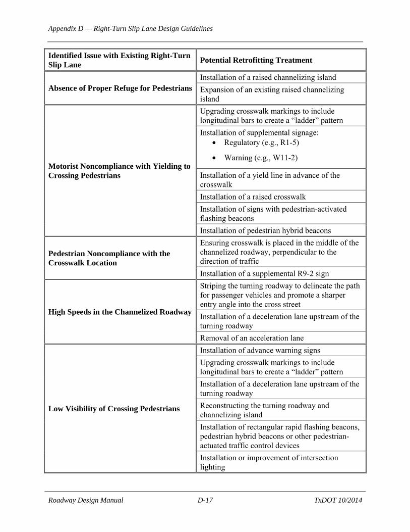
Appendix D — Right-Turn Slip Lane Design Guidelines
Roadway Design Manual D-17 TxDOT 10/2014
Identified Issue with Existing Right-Turn Slip Lane
Potential Retrofitting Treatment
Absence of Proper Refuge for PedestriansInstallation of a raised channelizing island
Expansion of an existing raised channelizing island
Motorist Noncompliance with Yielding to Crossing Pedestrians
Upgrading crosswalk markings to include longitudinal bars to create a “ladder” pattern
Installation of supplemental signage: • Regulatory (e.g., R1-5)
• Warning (e.g., W11-2)
Installation of a yield line in advance of the crosswalk
Installation of a raised crosswalk
Installation of signs with pedestrian-activated flashing beacons
Installation of pedestrian hybrid beacons
Pedestrian Noncompliance with the Crosswalk Location
Ensuring crosswalk is placed in the middle of the channelized roadway, perpendicular to the direction of traffic
Installation of a supplemental R9-2 sign
High Speeds in the Channelized Roadway
Striping the turning roadway to delineate the path for passenger vehicles and promote a sharper entry angle into the cross street
Installation of a deceleration lane upstream of the turning roadway
Removal of an acceleration lane
Low Visibility of Crossing Pedestrians
Installation of advance warning signs
Upgrading crosswalk markings to include longitudinal bars to create a “ladder” pattern
Installation of a deceleration lane upstream of the turning roadway
Reconstructing the turning roadway and channelizing island
Installation of rectangular rapid flashing beacons, pedestrian hybrid beacons or other pedestrian-actuated traffic control devices
Installation or improvement of intersection lighting
Appendix D — Right-Turn Slip Lane Design Guidelines
Roadway Design Manual D-18 TxDOT 10/2014
Identified Issue with Existing Right-Turn Slip Lane
Potential Retrofitting Treatment
Excessive Head Turning to Spot Oncoming Traffic
Reconfiguring the channelizing island and turning roadway such that the angle of entry is closer to 70 degrees
Absence of Proper Refuge for Pedestrians
Where the channelizing island along a right-turn slip lane is painted and does not provide adequate refuge for crossing pedestrians, consideration should be given to installing a raised island. Raised pedestrian islands reduce the crossing distance for pedestrians by allowing pedestrians to cross the through lanes and turning roadway separately while taking refuge on the island between. The reduction in crossing distance may also improve signal timing. Furthermore, raised islands allow for moving the stop line downstream to increase the intersection capacity and safety for motorists.
At intersections where there is a raised channelizing island but it is not large enough to provide refuge for pedestrians, the island should be expanded to establish an adequate landing area for pedestrians and comply with ADA regulations. The minimum recommended size is 50 ft2 [4.5 m2] for urban intersections and 75 ft2 [7.0 m2] for rural intersection; 100 ft2 [9.0 m2] is preferable for both urban and rural intersections.
Motorist Noncompliance with Yielding to Crossing Pedestrians
At intersections where there is a concern that motorists are failing to yield to crossing pedestrians, several treatments to improve compliance can be considered. These treatments are intended to achieve one or both of the following: improve the visibility of the crosswalk and slow right-turning motorists. When visibility is a concern and the crossing is currently marked, consideration may be given to upgrading the crosswalk markings to include longitudinal bars and incorporate a “ladder” pattern. An advanced warning sign (W11-2) may also be installed (see Figure D-4). For additional emphasis, a yield line may be placed in advance of the crosswalk with a “Yield Here to Pedestrians” (R1-5) sign (see Figure D-3).
In areas where pedestrian activity is moderate to high, raised crosswalks may be installed to slow turning motorists and improve their likelihood of yielding to crossing pedestrians. However, raised crosswalks are not recommended along high-speed facilities. Signs with pedestrian-actuated flashing beacons and pedestrian hybrid beacons may be installed to provide an advanced warning to approaching motorists of the need to comply with the crossing location. Caution must be taken when installing beacons where pedestrian activity is minimal and the infrequent activation of these beacons may violate driver expectations.
NCHRP Report 562 provides additional guidance concerning different types of crossing treatments based on observed conditions, including thresholds for pedestrian and vehicle volumes and roadway speed5.
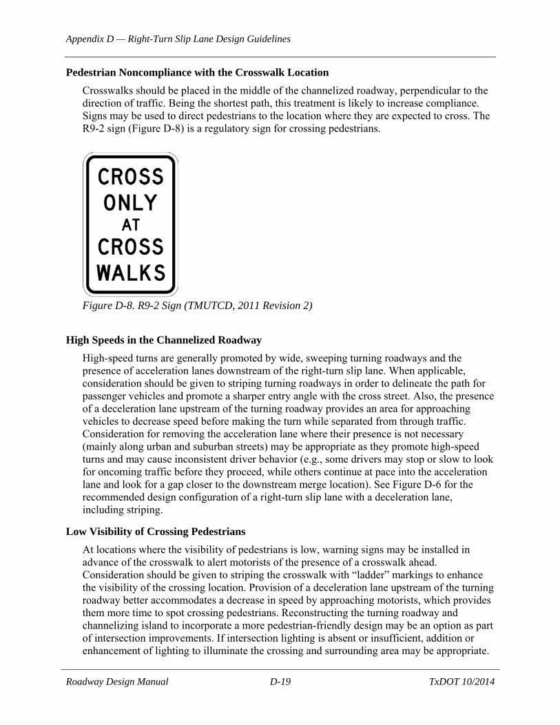
Appendix D — Right-Turn Slip Lane Design Guidelines
Roadway Design Manual D-19 TxDOT 10/2014
Pedestrian Noncompliance with the Crosswalk Location
Crosswalks should be placed in the middle of the channelized roadway, perpendicular to the direction of traffic. Being the shortest path, this treatment is likely to increase compliance. Signs may be used to direct pedestrians to the location where they are expected to cross. The R9-2 sign (Figure D-8) is a regulatory sign for crossing pedestrians.
Figure D-8. R9-2 Sign (TMUTCD, 2011 Revision 2)
High Speeds in the Channelized Roadway
High-speed turns are generally promoted by wide, sweeping turning roadways and the presence of acceleration lanes downstream of the right-turn slip lane. When applicable, consideration should be given to striping turning roadways in order to delineate the path for passenger vehicles and promote a sharper entry angle with the cross street. Also, the presence of a deceleration lane upstream of the turning roadway provides an area for approaching vehicles to decrease speed before making the turn while separated from through traffic. Consideration for removing the acceleration lane where their presence is not necessary (mainly along urban and suburban streets) may be appropriate as they promote high-speed turns and may cause inconsistent driver behavior (e.g., some drivers may stop or slow to look for oncoming traffic before they proceed, while others continue at pace into the acceleration lane and look for a gap closer to the downstream merge location). See Figure D-6 for the recommended design configuration of a right-turn slip lane with a deceleration lane, including striping.
Low Visibility of Crossing Pedestrians
At locations where the visibility of pedestrians is low, warning signs may be installed in advance of the crosswalk to alert motorists of the presence of a crosswalk ahead. Consideration should be given to striping the crosswalk with “ladder” markings to enhance the visibility of the crossing location. Provision of a deceleration lane upstream of the turning roadway better accommodates a decrease in speed by approaching motorists, which provides them more time to spot crossing pedestrians. Reconstructing the turning roadway and channelizing island to incorporate a more pedestrian-friendly design may be an option as part of intersection improvements. If intersection lighting is absent or insufficient, addition or enhancement of lighting to illuminate the crossing and surrounding area may be appropriate.
Appendix D — Right-Turn Slip Lane Design Guidelines
Roadway Design Manual D-20 TxDOT 10/2014
Other potential treatments include rectangular rapid flashing beacons, pedestrian hybrid beacons, or other pedestrian-actuated traffic control devices that alert motorists to the presence of the crossing location only when pedestrians are present. This not only improves the safety conditions at these intersections but actuation may reduce the impact to motorists’ mobility.
Excessive Head Turning to Spot Oncoming Traffic
At intersections where motorists are required to turn their heads excessively to observe oncoming traffic, consideration should be given to reconfiguring the channelizing island and turning roadway such that the angle of entry is closer to 70 degrees. As a result, navigating the turning roadway does not require as much physical effort to observe cross street traffic. This may involve reconstructing the channelizing island/outside curb radius or restriping the island area and turning path.
Slip Lane Removal
If none of the available right-turn slip lane treatments will address existing safety problems at the turning roadway, and pedestrian activity is very high, consideration may be made to close the slip lane and transform the area into a pedestrian-friendly corner with street furniture, benches, and landscaping. A shared through-right-turn lane would replace the slip lane to accommodate the right turning movement. However, this option should be carefully considered as the removal of the slip lane may eliminate a number of benefits, including the reduction of vehicular delays and rear-end crashes.
Appendix D — Right-Turn Slip Lane Design Guidelines
Roadway Design Manual D-21 TxDOT 10/2014
Section 5 — References
1. A Policy on Geometric Design of Highways and Streets, American Association of Highway and Transportation Officials, 2011.
2. “A Real Head Turner: Urban Smart Channels Debut in Ottawa”, Milestones, 8(3), Ontario Good Roads Association, Oakville, Ontario, pp. 49-51, 2008.
3. Access Management Manual, Texas Department of Transportation, 2011.
4. ADA Standards for Accessible Design, Americans with Disabilities Act, 2010.
5. Fitzpatrick, K., Turner, S., Brewer, M., Carlson, P., Ullman, B., Trout, N., . . . Lord, D, “TCRP Report 112/NCHRP Report 562: Improving Pedestrian Safety at Unsignalized Intersections,” Transportation Research Board of the National Academies, Washington, D.C., 2006.
6. Guide for the Development of Bicycle Facilities, American Association of Highway and Transportation Officials, 2012.
7. Ottawa Pedestrian Plan, City of Ottawa, Ontario, Canada, 2009.
8. Pedestrian Facilities Curb Ramps Ped 12-A, Texas Department of Transportation, 2012.
9. Pedestrian Refuge Island, Metropolitan Transportation Commission.
10. Texas Manual on Uniform Traffic Control Devices, Texas Department of Transportation, 2011.
11. NCHRP 3-89: Design Guidance for Channelized Right-Turn Lanes, National Cooperative Highway Research Program, Transportation Research Board, ongoing.