Embed Size (px)
Citation preview

A REPORT ON INTRODUCTION TO INDUSTRIALELECTRICAL SYSTEMS (IIES)
on 20th to 22nd September 2017
Switching training center–Pune: Training Programme on LowVoltage Switchgear Protection attended by the students of IIIElectrical and Electronics Engineering students.
Submitted By III EEE Students
SHRI VISHNU ENGINEERING COLLEGE FOR WOMEN
(Autonomous)
Approved by AICTE & Affiliated to JNTU-K, Kakinada
Accredited with ‘A’ Grade by NAAC & NBA
Vishnupur, Bhimavaram, West Godavari Dist. – 534 202, Andhra Pradesh, India.

Details of L&T:
Larsen & Toubro is an Indian multi national conglomerate Headquartered in Mumbai. It was founded by two Danish engineers takingrefuge in India.This company has business interests in engineering,construction,manufacturing goods, information technology, and financialservices, and has offices worldwide. It is one of the largest and mostrespected companies in India's private sector.
Agenda of the Programme:
Day 1:
Introduction to Low Tension Switchgear Contactors:
Construction, Operation and SelectionDemo on Contactor
Film on Safety Various Causes on Motor Failure Thermal Overload Relay- Construction, Operation and
Application Demonstration and Testing of BMR

Day 2:
AC Motor Starter- Overview & Demonstration (Wiring of DOL,SASD,FASD Starter)
HRC Fuses: Role, Types Switches- Role and Features Demonstration of Fuses, Switches, SDFs MCCB- Introduction Demonstration of MCCB
Day 3:
ACB- Role, Operation, Types, Features and Application Understanding and Identification of various parts of ACB Overview of MCB & RCCB
Conceptual Details in a brief manner:
Introduction to LV System:
The International Electrotechnical Commission (IEC) definessupply system low voltage as voltage in the range 50–1000 V AC or120–1500 V DC.
In electrical power systems low voltage most commonly refersto the mains voltages as used by domestic and light industrial andcommercial consumers. "Low voltage" in this context still presents a riskof electric shock, but only a minor risk of electric arcs through the air.
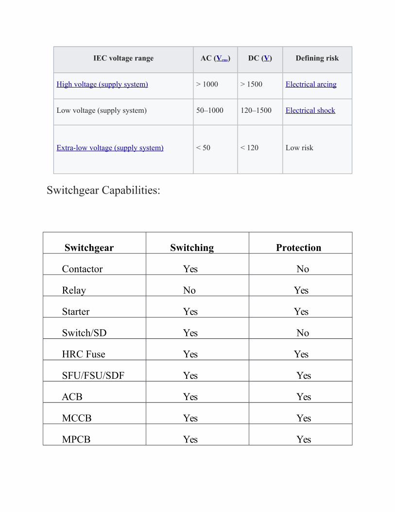
IEC voltage range AC (Vrms) DC (V) Defining risk
High voltage (supply system) > 1000 > 1500 Electrical arcing
Low voltage (supply system) 50–1000 120–1500 Electrical shock
Extra-low voltage (supply system) < 50 < 120 Low risk
Switchgear Capabilities:
Switchgear Switching Protection
Contactor Yes No
Relay No Yes
Starter Yes Yes
Switch/SD Yes No
HRC Fuse Yes Yes
SFU/FSU/SDF Yes Yes
ACB Yes Yes
MCCB Yes Yes
MPCB Yes Yes
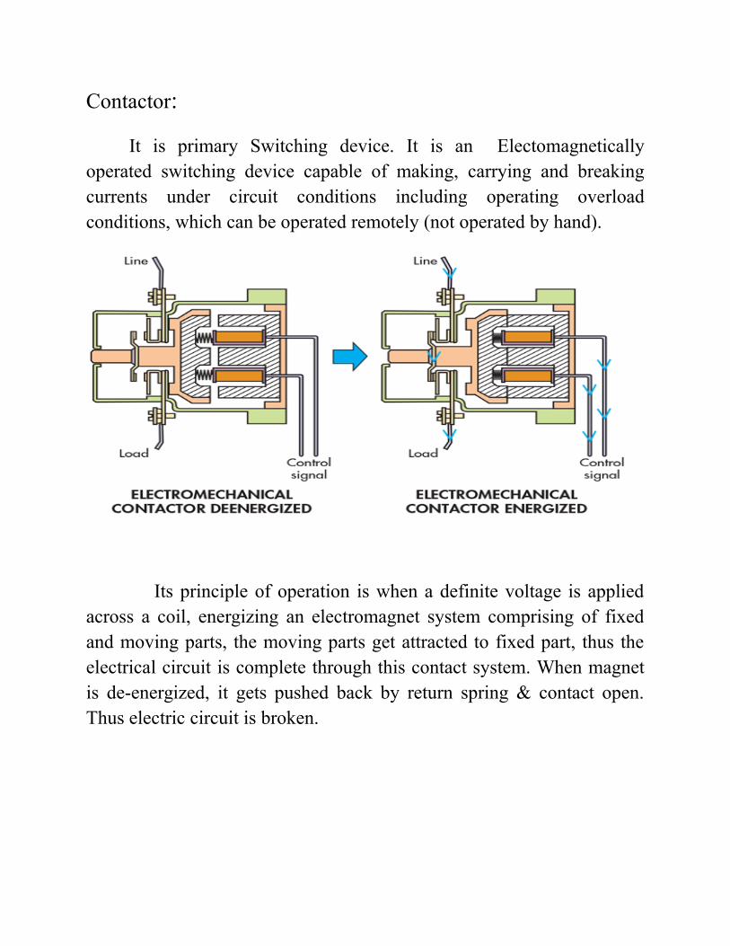
Contactor:
It is primary Switching device. It is an Electomagneticallyoperated switching device capable of making, carrying and breakingcurrents under circuit conditions including operating overloadconditions, which can be operated remotely (not operated by hand).
Its principle of operation is when a definite voltage is appliedacross a coil, energizing an electromagnet system comprising of fixedand moving parts, the moving parts get attracted to fixed part, thus theelectrical circuit is complete through this contact system. When magnetis de-energized, it gets pushed back by return spring & contact open.Thus electric circuit is broken.

Advantages:
1 .High number of make-break operations
2. High making & breaking capacity
3. Remote ON/OFF
4. High mechanical & electrical life
5. No volt protection
6. High frequency of operations
RELAY:
The term Relay generally refers to a device that provides anelectrical connection between two or more points in response to theapplication of a control signal. The most fundamental control of any

equipment is the ability to turn it “ON” and “OFF”. The easiest way todo this is using switches to interrupt the electrical supply. Althoughswitches can be used to control something, they have theirdisadvantages. The biggest one is that they have to be manually(physically) turned “ON” or “OFF”. Also, they are relatively large, slowand only switch small electrical currents. Relays can have single or multiple contacts within a singlepackage with the larger power relays used for mains voltage or highcurrent switching applications being called “Contactors”. They are usedin general electrical and electronic control or switching circuits.
Starter:
A Starter is a device that controls the use of electrical power toequipment, usually a motor. As the name implies, starters "start" motors.They can also stop them, reverse them, and protect them. They are madefrom two building blocks, Contactors and Overload Protection.
1. Contactors control the electric current to the motor. Their functionis to repeatedly establish and interrupt an electrical power circuit.
2. Overload Protection protects motors from drawing too muchcurrent, overheating, and from literally "burning out".
A starter turns an electric motor or motor controlled electrical equipmenton or off, while providing overload protection. Starters represent anotherevolution in motor control applications. The two main types of startersare Manual Starters and AC Magnetic Motor Starters, commonly knownas Motor Starters.
Switch/SD:
A circuit breaker is an automatically operated electrical switch designed to protect an electrical circuit from damage caused by excess current, typically resulting from an overload or short circuit. Its basic function is to interrupt current flow after a fault is detected.
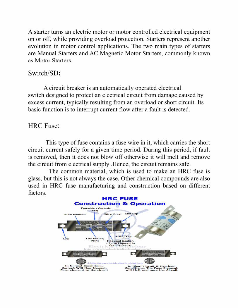
HRC Fuse:
This type of fuse contains a fuse wire in it, which carries the shortcircuit current safely for a given time period. During this period, if faultis removed, then it does not blow off otherwise it will melt and removethe circuit from electrical supply .Hence, the circuit remains safe. The common material, which is used to make an HRC fuse isglass, but this is not always the case. Other chemical compounds are alsoused in HRC fuse manufacturing and construction based on differentfactors.

Advantages of HRC Fuse:
1. It clears high as well as low fault currents.
2. Do not deteriorate with age.
3. Having high-speed operation.
4. Provides reliable discrimination.
5. Require no maintenance.
6. Cheaper than other circuit interrupting devices with same rating.
7. Permit consistent performance
8. Fusing operation is fast without Noise and Smoke
Disadvantages of H.R.C Fuse:
1. After each operation, they have to be replaced.
2. Heat being produced by the arc may affect the associated switches
Different types of HRC Fuses

SFU/FSU/SDF:
The Switch Disconnector Fuse (SDF) has the following functions: 1. Back up switching in case of contactor fails to operate. 2. Isolation for the maintenance of motor feeder.
This switching device is expected to do not only switching but
also it has to give isolation in open position for maintenance purpose.

ACB (Air Circuit Breaker):
A circuit breaker is a device, which can
1. Make or Break a circuit manually or by remote control undernormal conditions
2. Break a Circuit automatically under fault conditions (like overcurrent, Short circuit, etc.) 3. Make a circuit manually or by remote control under faultconditions
The type of circuit breaker, which operates in air (where air-blast as an arc quenching medium) at atmospheric pressure, is known tobe an Air Circuit Breaker. Air circuit breaker has completely replaced byoil circuit breaker. The working principle of Air Circuit breaker is rather differentfrom other types of circuit breaker.The main aim of circuit breaker is toprevent reestablishment of arcing after current zero where the contactgap will withstand the system recovery voltage. During interruption ofarc, it creates an arc voltage instead of supply voltage. Arc voltage isdefined as the minimum voltage required for maintaining arc .The circuitbreaker increases the voltage in three different ways:

1. Arc voltage can be increased by cooling arc plasma. As soon asthe temperature of arc plasma motion of particle in arc plasma isreduced, more voltage gradient will be required to maintain the arc.
2. By splitting the arc into a number of series will increases the arcvoltage.
3. Arc voltage can be increased by lengthening the arc path. Assoon length of arc path is increased the resistance path will increasemore arc voltage is applied across the arc path hence arc voltage isincreased.
MCCB (Moulded case circuit breaker):
Characteristics:
Rated current up to 1000 A.1. Trip current may be adjustable.2. Thermal or thermal-magnetic
operation
MPCB (Motor Protection Circuit Breaker):
MPCB is a specialized electromechanical device that can be used with motor circuits of both 60 Hz and 50 Hz. It has several functions that allow it to provide a safe electrical supply for motors:
1. Protection against electrical faults such as short circuits, line-to-ground faults and line-to-line faults. The MPCB can interrupt anyelectrical fault that is below its breaking capacity.

2. Motor overload protection, when a motor draws electriccurrent above its name plate value for an extended period of time.Overload protection is normally adjustable in MPCBs. 3. Protection against phase unbalances and phase loss. Bothconditions can severely damage a three-phase motor, so the MPCBwill disconnect the motor in either case as soon as the fault isdetected. 4. Thermal delay to prevent the motor from being turned backon immediately after an overload, giving the motor time to cooldown. An overheated motor can be permanently damaged if it isturned back on. Motor Circuit Switching – MPCBs are normally equipped withbuttons or dials for this purpose. Fault Signaling – Most models of motor protection circuitbreakers have a LED display that is turned on whenever the MPCBhas tripped. This is a visual indication for nearby personnel that afault has occurred and the electric motor must not be connected againuntil the fault is addressed.
RCCB (Residual Current Circuit Breaker):
Phase (line) and Neutral both wires connected through RCD.
1. It trips the circuit when there is earth fault current.
2. The amount of current flows through the phase (line) should return through neutral .
It detects by RCD if any mismatch between two currents flowing through phase and neutral detect by -RCD and trip the circuit within 30Miliseconed.

Characteristics:
1. If a house has an earth system connected to an earth rodand not the main incoming cable, then it must have all circuitsprotected by an RCD (because u might not be able to get enoughfault current to trip a MCB) 2. RCDs are an extremely effective form of shock protection