Embed Size (px)
Citation preview
44 October 2011
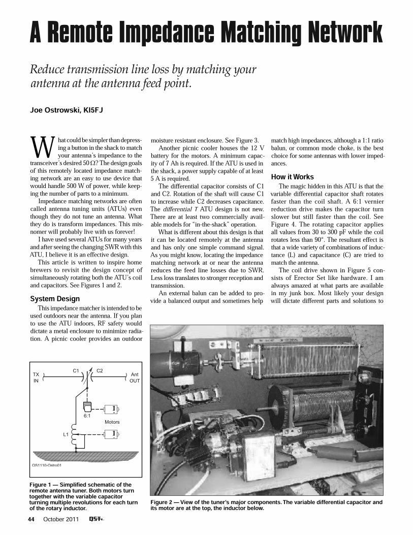
W hat could be simpler than depress-ing a button in the shack to match your antenna’s impedance to the transceiver’s desired 50 ? The design goals of this remotely located impedance match-ing network are an easy to use device that would handle 500 W of power, while keep-ing the number of parts to a minimum.Impedance matching networks are often called antenna tuning units (ATUs) even though they do not tune an antenna. What they do is transform impedances. This mis-nomer will probably live with us forever! I have used several ATUs for many years and after seeing the changing SWR with this ATU, I believe it is an effective design.This article is written to inspire home brewers to revisit the design concept of simultaneously rotating both the ATU’s coil and capacitors. See Figures 1 and 2. System DesignThis impedance matcher is intended to be used outdoors near the antenna. If you plan to use the ATU indoors, RF safety would dictate a metal enclosure to minimize radia-tion. A picnic cooler provides an outdoor
A Remote Impedance Matching Network Reduce transmission line loss by matching your antenna at the antenna feed point.
Joe Ostrowski, KI5FJ
Figure 2 — View of the tuner’s major components. The variable differential capacitor and its motor are at the top, the inductor below.
Figure 1 — Simplifi ed schematic of the remote antenna tuner. Both motors turn together with the variable capacitor turning multiple revolutions for each turn of the rotary inductor.
moisture resistant enclosure. See Figure 3.Another picnic cooler houses the 12 V battery for the motors. A minimum capac-ity of 7 Ah is required. If the ATU is used in the shack, a power supply capable of at least 5 A is required.The differential capacitor consists of C1 and C2. Rotation of the shaft will cause C1 to increase while C2 decreases capacitance. The differential T ATU design is not new. There are at least two commercially avail-able models for “in-the-shack” operation.What is different about this design is that it can be located remotely at the antenna and has only one simple command signal. As you might know, locating the impedance matching network at or near the antenna reduces the feed line losses due to SWR. Less loss translates to stronger reception and transmission.An external balun can be added to pro-vide a balanced output and sometimes help
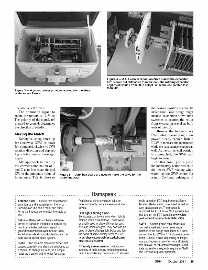
match high impedances, although a 1:1 ratio balun, or common mode choke, is the best choice for some antennas with lower imped-ances.How it WorksThe magic hidden in this ATU is that the variable differential capacitor shaft rotates faster than the coil shaft. A 6:1 vernier reduction drive makes the capacitor turn slower but still faster than the coil. See Figure 4. The rotating capacitor applies all values from 30 to 300 pF while the coil rotates less than 90°. The resultant effect is that a wide variety of combinations of induc-tance (L) and capacitance (C) are tried to match the antenna.The coil drive shown in Figure 5 con-sists of Erector Set like hardware. I am always amazed at what parts are available in my junk box. Most likely your design will dictate different parts and solutions to
OSTROWSKI.indd 44 8/23/2011 12:46:53 PM
October 2011 45
the desired position for the 10 meter band. Your design might include the addition of two limit switches to restrict the roller from exceeding travel at both ends of the coil.Observe the in the shack SWR while transmitting a low power, steady carrier. Rotate CCW to increase the inductance while the capacitance changes as well. As the correct coil position is approached, the SWR will begin to swing.At this point, jog or pulse the momentary button switch to the lowest SWR reading while watching the SWR meter for a null. Continue pulsing until
the mechanical drives.The command signal to rotate the motors is 12 V dc. The polarity of the signal, ref-erenced to ground, determines the direction of rotation.Making the MatchSimply selecting either up for clockwise (CW) or down for counterclockwise (CCW) rotation direction and depress-ing a button makes the magic appear!My approach to finding the correct combination of L and C is to first rotate the coil CW to the minimum value of inductance. This is close to
Hamspeak
Figure 3 — A picnic cooler provides an outdoor moisture resistant enclosure.
Figure 4 — A 6:1 vernier reduction drive makes the capacitor turn slower but still faster than the coil. The rotating capacitor applies all values from 30 to 300 pF while the coil rotates less than 90°.
Figure 5 — Junk box gears are used to make the drive for the rotary inductor.
Antenna tuner — Device that sits between an antenna and a transmission line, or a transmission line and a radio, and trans-forms the impedance to match the radio or line.
Balun — Balanced to unbalanced trans-former or transition intended to convert sig-nals from a balanced (with respect to ground) transmission system to an unbal-anced (one side at ground potential, such as coax cable) transmission system.
Diode — Two element electronic device that passes current in one direction only. Used as a rectifier to change ac to dc, as a simple mixer, as a switch and for other functions.
Available as either a vacuum tube, or more commonly now as a semiconductor device.
LED, light emitting diode — Semiconductor device from which light is emitted when current flows. These were originally used in place of incandescent bulbs as indicator lights. They now can be used in place of larger light bulbs and form the basis of some display screens. See hyperphysics.phy-astr.gsu.edu/hbase/electronic/leds.html.
RF safety assessment — Evaluation of intensity of radio energy emanating from a radio transmitter and comparison to allowed
levels based on FCC requirements. Every Amateur Radio station is required to perform such an assessment. The process is described the ARRL book RF Exposure and You, and on the FCC website at www.fcc.gov/oet/info/documents/bulletins/#65.
SWR — Standing wave ratio. Measure of how well a load, such as an antenna, is matched to the design impedance of a trans-mission line. An SWR of 1:1 indicates a perfect match. Coaxial cables, depending on length, type and frequency can often work efficiently with an SWR of 3:1, sometimes higher. Solid state transmitters frequently require an SWR of 2:1 or less for proper operation.
OSTROWSKI.indd 45 8/23/2011 12:46:59 PM
46 October 2011
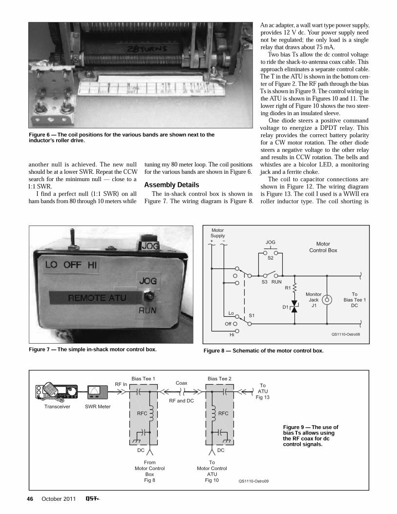
Figure 6 — The coil positions for the various bands are shown next to the inductor’s roller drive.
Figure 7 — The simple in-shack motor control box. Figure 8 — Schematic of the motor control box.
Figure 9 — The use of bias Ts allows using the RF coax for dc control signals.
another null is achieved. The new null should be at a lower SWR. Repeat the CCW search for the minimum null — close to a 1:1 SWR.I find a perfect null (1:1 SWR) on all ham bands from 80 through 10 meters while
tuning my 80 meter loop. The coil positions for the various bands are shown in Figure 6.Assembly DetailsThe in-shack control box is shown in Figure 7. The wiring diagram is Figure 8.
An ac adapter, a wall wart type power supply, provides 12 V dc. Your power supply need not be regulated; the only load is a single relay that draws about 75 mA. Two bias Ts allow the dc control voltage to ride the shack-to-antenna coax cable. This approach eliminates a separate control cable. The T in the ATU is shown in the bottom cen-ter of Figure 2. The RF path through the bias Ts is shown in Figure 9. The control wiring in the ATU is shown in Figures 10 and 11. The lower right of Figure 10 shows the two steer-ing diodes in an insulated sleeve.One diode steers a positive command voltage to energize a DPDT relay. This relay provides the correct battery polarity for a CW motor rotation. The other diode steers a negative voltage to the other relay and results in CCW rotation. The bells and whistles are a bicolor LED, a monitoring jack and a ferrite choke.The coil to capacitor connections are shown in Figure 12. The wiring diagram is Figure 13. The coil I used is a WWII era roller inductor type. The coil shorting is
OSTROWSKI.indd 46 8/23/2011 12:47:08 PM
October 2011 47
Figure 13 — Schematic diagram of the ATU portion of the remote unit and parts list of total project.B1 — Battery, vehicle jump start type, 12 V, minimum of 7 Ah capacity (Harbor Freight 38391).BT1, BT2 — Bias T dc power injector (MFJ-4116).C1, C2 — Capacitor, differential type, 30-300 pF (MFJ-282-2015).D1 — Diode, LED, bi-color (red-green) (Mouser 606-7011X1/5).D2-D5 — Diode, 1N4005 (Mouser 821-1N4005).F1 — Fuse, 10 A, fast blow (RadioShack 270-1015).FB — Ferrite beads (Palomar FB-56).J1 — Jack, RCA chassis mount (RadioShack 274-852).K1, K2 — 12 V, 10 A DPDT plug-in relay with socket (Radio Shack 275-0218).L1 —Roller inductor, approximately 29 µH (MFJ 404-1052).Mot1, Mot2 — Motor from discarded Skil 2.4 V electric screwdriver.PS1 — 120 V ac adapter with 12 V dc output to 500 mA (RadioShack 273-357).R1 — 2.2 k , 1⁄8 W resistor (RadioShack 271-007).R2, R3 — 6 resistor, fi ve 30 , 10 W resistors in parallel (Mouser 284-HS10-30).S1 — DPDT switch, center-off (RadioShack 275-664).S2 — SPST switch, momentary contact (RadioShack 275-1547).S3 — SPST switch (RadioShack 275-645).S4, S5 — SPST switch, ceramic (Surplus Sales of Nebraska SWR-B-52108).Vernier reduction ball drive, 6:1 (MFJ-729-0142-1).
done by two tensioned bars, a very high current design. This treasure was mistakenly stored in the junk box. Your coil can be any roller inductor of about 30 turns. See the component list.No attempt has been made to provide coil position information. In practice, it is simple to find the band you last matched and then rotate CW for up or CCW for down to another band. The most challenging aspect of this project was to find a suitable motor and couple it to the capacitor and coil.The bottom line is this ATU design is a relatively simple approach to impedance matching. It uses no microprocessors or relays to switch RF components. Joe Ostrowski, KI5FJ, holds an Amateur Extra class license and a FCC Commercial Operator license with Ship Radar endorsement. Joe was first licensed in 1963 as WN2GKU, as a teenager. He rejoined the hobby in 1990 and now operates all HF bands. While stationed with the US Air Force in England he operated as GØRPN. Joe can be reached at POB 691, Dona Ana, NM 88032 or at [email protected].
Figure 10 — The motor control wiring in the ATU.
Figure 11 — View of the relays wired and ready to install
Figure 12 — Detailed view of the interconnection of the tuning elements.
OSTROWSKI.indd 47 8/23/2011 12:47:18 PM