Embed Size (px)
Citation preview
4 . c . 5
A REINFORCED BRICKWORK RETAINING WALL
A, H,P , MA URENBRECHER StructuraZ CZO?j Products , Ltd., Potters Bar, Herts , Great Britain
A REINFORCED BRICKWORK RETAINING WALL
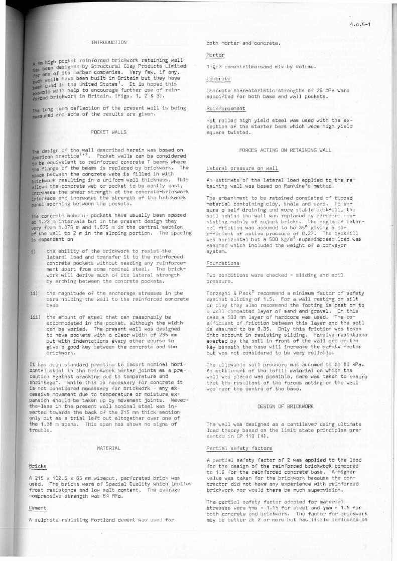
This papel' considers the uZtimate load design and con
struction of a 4m high reinforced brickwork retaining
wall .
The brickwork wall , built on a reinforced concrete
base, is held to the base by reinforced concrete
pockets incorporated in the tension side of the wall .
The thickness of the wall is 440mm at the base re
ducing in two s teps to 215mm at t he top o
The~ong term lateral deflection of the finished wall
is being measured.
UN MUR DE SOUTENEMENT EN MACONNERIE ARMEE
Ce document a trait au calcul de la charge de rupture
et à la construction d 'un mur de soutenement de 4 m
de haut en maçonnerie armée .
Le mur en maçonner ie, construit sur une fondation en
béton armé, est fixé à celle- ci par des ancrages en
béton armé incorporés dans le côté tendu du mur .
L'épaisseur du mur est de 440 mm à la base, se rédui
sant en deux gradins jusqu ' à 215 ~n au sommet .
On mesure la fleche latérale à long terme du mur ter
miné .
STUETZMAUER AUS BEWEHRTEM
ZIEGELMA UERWERK
Der Beitrag behandelt den Standsicherheitsnachweis
und die Konstruktion einer 4 m hohen Stützmauer in
bewehrtem Mauerwerk .
Die Ziegelwand wurde auf einem Stah lbetonfun dament
errichtet und wird mit diesem du.rch eine Stahlbeton
tasche , di e sich auf der Zugseite der Wand bef inékt,
verbunden . Die Dicke der Wand ist 440 mm am Fuss und
wird in zwei Stufen auf 215 mm an ékr Oberkannte ver
mindert .
Es wi r d die Langzeithorizontalverschiebung ékr f erti
gen Wand gemessen .
EEN GRONDKEERMUUR IN GEWAPEND METSELWERK
Deze mededeling behandelt de berekening volgens de
br eukmethode en de bouw van een 4 m hoge grondkeer
muur in gewapend metselwerk .
De muur, gebouwd op een betonbasis, wordt gehouden
door balken in gewapend beton, die ingebouwd zijn in
de trekzijde van de muur . De muurdikte is 440 mm aan
de voet en reduceer t zich in twee trappen t ot 215 mm
aan de top o
De zijdelingse buiging na lange periode werd gemeten .

INTRODUCTIDN
4m high pocket reinforced brickwork retaining wall been designed by Structural Clay Products Limited one of its member c ompanies. Very few, if any, wall s have been built i n Britain but they have use d in the United States 1 • It is hoped this le wi ll help to encourage further use of rein
brickwork in Britain. (Figs. 1, 2 & 3).
term deflection of the pres ent wall is being and some of the results are give n .
POCKET WALLS
The design of the wall described herein was based on ~rican practice 1 ,2 Pocket walls can be considered to be equivalent to reinforced concret e T beams where the flange of t he beams is replaced by brickwork. The apace between the concrete webs is filled in with brickwork resulting in a uniform wall thickness. This allows the concrete web or pocket to be easily cast, increases the shear strength at the concrete-brickwork interface and increases the strength of the brickwork panel spanning between the pockets.
lhe concrete webs or pockets have usually been spaced at 1.22 m intervals but in the present design they vary from 1 .375 m and 1.575 m in the central section Df the wall to 2 m in the sloping portion . The spacing i 5 dependent on
i) the ability of the brickwork to resist the lateral load and transfer it to the reinforced concrete pockets without needing any reinforcement apart from some nominal steel . The brickwork will derive much of its lateral strength by arching between the concrete pockets.
ii) the magnitude of the anchorage stresses i n the bars holding the wall to the reinforced concrete bas e
iii ) the amount of steel that can reasonably be accommodated in the pocket, although the width can be varied. The present wall was designed to have pockets with a clear width of 235 mm but with indentations every other course to give a good key between the concrete and the brickwork.
It has been standard practice to insert nomina l horizontal steel in the brickwork mortar joints as a precaution ayainst cracking due to temperature and shrinkage . While this is necessary for concrete it is not considered necessary for brickwork - any excessive movement due to temperature or moisture expansion should be taken up by movement joints. Neverthe-less in the present wall nominal steel was inserted towards the back of the 215 mm thick section only but as a trial left out altogether over one of the 1.38 m spans . This span has shown no signs of trouble.
MATERIAL
Bricks
A 215 x 102.5 x 65 mm wirecut, perforated brick was used . The bricks were of Special Quality which implies frost resistance and low salt contento The average compressive strength was 64 MPa.
Cement
A sulphate resisting Portland cement was used for
both mortar and concrete.
Mortar
1:~:3 cement:lime: sand mix by vo lume .
Concrete
Concrete characteristic strengths of 25 MPa were specified for both base and wall pockets.
Reinforc eme nt
4.c. 5-1
Hot rolled high yield steel was us ed with the exception of the starter bars which were high yield square twisted.
FORCES ACTING ON RETAINING WALL
Lateral pressure on wall
An estimate of the lateral load applied to the retaining wall was based on Rankine's method.
The embankment to be retained consisted of tipped material containing clay, shale and sand. To ensure a self draining and more stable backfill , the soil behind the wall was replaced by hardcore consisting main l y of reject bricks. , The angle of internaI friction was assumed to be 35° giving a coefficient of active pressure of 0.27. The backfi ll was horizontal but a 500 kg/m2 su perimposed load was assumed which included the weight of a conveyor system .
Foundat ions
Two conditions were checked - sliding and soi l pressure.
Terzaghi & Peck 2 recommend a minimum factor of safety against sliding of 1.5. For a wall resting on silt or clay they also recommend the footing is cast on to a well compacted layer of sand and graveI. In this case a 500 mm layer of hardcore was used. The coefficient of friction between this layer and the soil is assumed to be 0.35. Only this frictio n was taken into account in resisting sliding. Passive resistance exerted by the soil in front of the wa ll and on the key beneath the base will increase the safety factor but was not considered to be very reliable.
The allowable soil pressure was assumed to be 80 kPa. As settlement of the infill mate rial on which the wall was placed was possible , care was taken to ensure that the resultant of the forces acting on the wall was near t he centre of the base.
DESIGN DF BRICKWORK
The wa ll was designed as a cantilever using ultimate load theory based on the limit state princip Ies presented in CP 110 (4).
Partial safety factors
A partial safety factor of 2 was applied to the ' load for the design of the reinforced brickwork compared to 1.6 for the reinforced concrete base. A highe r value was taken for the brickwork beca use the oontractor did not have any experience with reinforced brickwork nor would there be much supervision o
The partial safety factor adopted for mate rial stresses were yms = 1.15 for steel and ymm = 1 .5 for both concrete and brickwork. The factor fo r brickwork may be better at 2 or more but has little influenceon
4 . c.5-2
the present designo
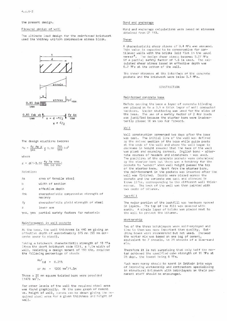
Flexura l design of wal l
The ultimate load design for the reinforced brickwork used the Whitney un i form compressive stress b lock .
t
0. 85 fmkllllllllllll yrmn
s t ress IfY / yms
0.85 f mk xb fl-'~----:----tj ~ yrmn z d _x / 2 ~ yms
x ( d / 2
The design equations become :
Mu = fy As z < 0 . 32 yms
where
z = d(1-0 . 59 fy As ymm ) fmk bd yms
Notatio n :
As
b
d
fmk
fy
z
yms, ymm
area of tensile steel
width of section
effecti ve depth
characteristic compressive strength of masonry
characteristic yield strength of steel
lever arm
part i al safety factors fo r materiaIs
Rei nforcement in wall pockets
At the base, the wall thickness is 440 mm giving an effective depth of approximately 375 mm (50 mm concrete cover to steel) .
Taking a brickwork characteris t ic strengt h of 18 MPa (from the draft brickwork code (5)) , a 1 . 5m width of wal l , resisting a design moment of 160 kNm , requires the fol l owing percentage of steel :
Asl bd 0 . 21%
or As
Three x 25 mm squa r e twisted bars were provided ( 1470 mm2
) .
For other le ve Is of the wa l l the required steel area was found graphica lly . On the same graph of moment VS . height of wall, curves can be drawn giving the required stee1 area for a given thickness and height of wa11.
Bond and anchorage
Bond and ancho rage ca1culations were based on stresses obtained from CP 110 .
Shear
A characteristic shear st r ess of 0 . 4 MPa was assumed . This va1ue is expected to be conservati ve for canti 1ever wa11s with the bri cks 1aid flat in the usual manner 6
• The design shear stress becomes 0 . 27 MPa if a partia1 safety fact or of 1 . 5 is us ed . The ca1-cu1ated shear stress based on effective depth was 0 . 2 MPa at the bottom of the wa11 .
The shea r stresses at the interface of the concrete pockets and the brickwork were below 0 . 1 MPa .
CONSTRUCT ION
Rein forced concrete base
Before casting the base a 1ayer of concrete blinding was placed on to a 0 . 5 m thick 1ayer of we11 compacted hardcore . Wooden shuttering was used for the sides of the base . The use of a safety factor of 2 for loads was justified because the starter bars were inadvertently placed 60 mm too far forward .
Wall
Wall construction commenced two days after the base was cast o The initial 1ine of the wa11 was defined by the raised section of th e base whi1e guide posts at t he ends of the wa11 and where the wa11 began to dec rease in height ensured that the face of the wa11 was plumb and coursing correct . English bond - a1ternate courses of headers and stretchers - was used . The positions of the concrete pockets were determined by the starter bars but there was a ten den cy for the pockets to ' wander ' when wa11 height passed the top of the starter bars. Apart from the starter bars , the r einforcement in the pockets was i nserted after the wa11 was finished. Boards were p1aced across the pockets and t he concret e was cast and vibrated in t hree 1ifts , corresponding to the different wa11 t hick nesses . The back of the wa11 was the n painted with two coats of bitumen .
Backfi ll
The major portion of the backfi1 1 was hardcore spread in layers . The top of the fill was covered with ea rth . A sing1e 1ayer of bricks was placed next to the wa11 to protect the bitumen .
Workmanship
Two of the three brick1ayers were se l f-employed and time to them was mo re imp ortant than quali ty. Batching bo xes were recommended but not used . Instead the mortar mix was based on one bag of cement, equiva1ent to 7 shove1s , to 21 s hove l s of a 1ime-sand mix o
Therefore it is not surprlslng that on1y ha1f the mortar achieved the specified cube strength of 11 MPa at 28 days , the lowest being 6 MPa .
Much more money shou1d be spent in Bri tain i nto ways of improving workmanship and contractors specia1ising in structural brickwork with bricklayers on their permanent staff shou1d be encouraged .
ng ~ted , of js
er-
ed e
the
ick-
d
rt
r -
I;JALL OEFLECTION
lat e r al deflection Df the wall is being monitored a t heodolite placed on a specially prepared conbase situated 15 m away from the side Df the wall .
Df s i ght Df the theodolite passes app r oxi -200 mm in front Df the wall on to the apex Df f Df a distant house. A steel rule placed at
ang les to the wall measured the distance Df the from t he line Df sight .
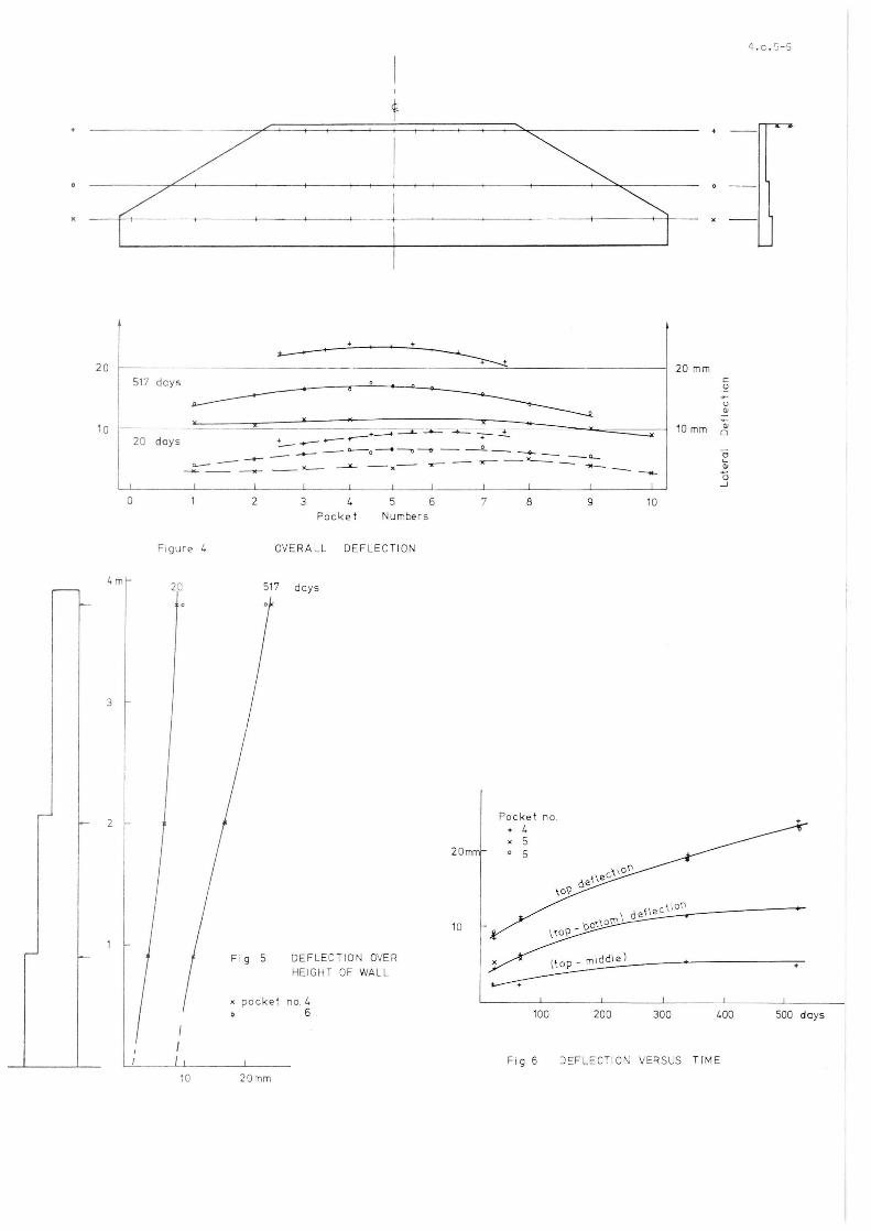
overall defle ction of the l,all measured at three . v8ls a l ong the l ength Df the wall is shown in Fig.
It shows the deflection 20 and 517 days after inlling. Note that the central section which is more
ly loaded deflects mosto
figure 5 shows the deflection over the height Df the l/a11 1. 37 m away from the centre pocKet. There is a s light reverse curvature, not a typical cantilever curve as may be expected. p, liKely cause is restraint by t he more lightly loaded sections Df the wall. The curves a l so show there is some sliding movement Df ~pro ximately Ô mm over 517 days but this could also be due to movement of the theodolite base.
Figure 6 shows a plot of wa ll deflections versus time. lhe di fference between the bottom and top leveI def lections gives an indication Df wall angular movement due to wall deformation and tilting. The graph shO\,s t he angular movement has almost stopped after 517 days. On t he other hand the overall movement as shovm by the t op leveI deflection is still increasing although at a decreasing rate . At 517 days the top deflection was about 24 mm Df vJhich approximately ô mm is sliding fOOvement.
4.c.5 - 3
REFE RENCE S
1. C. R. ABEL & M.R. COCHRAN. A reinforced bricK mason r y retaining wall with reinforcement in pocKets . SIBMAC Proceedings , The Bri tish Ceramic Res earch Association, StoKe-on - Trent 1971.
2 . BRICK & TILE SERVICE I NC. RBM retaining waÚs. Gre ens bo ro , N. C. U.S .A .
3. K. TERZAGHI & R. B. PECK. Soil Mechanics in Engineering Practice . J. Wiley & Sons, New York 1967 .
4. BRITISH STANDARDS I NSTITUT ION . CP 11 0 :1 972. The structu r a l us e of concret e.
5 . IBIO. Oraft st andard BLCP/29: 1974 . The structural use of maso nry - Part 1:Unreinforce d masonry .
6 . STRUCTURAL CLAY PRO DUCTS LIMI TEO. SCP 10 . Reinforced b rickwork cant i lever wa l ls. To be published .
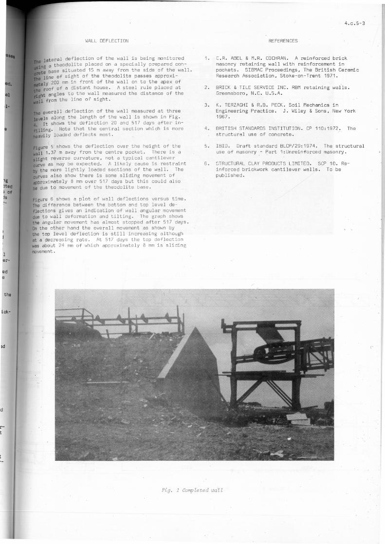
Fig. 1 Completed 1JaZl

I I 1
1-
4 . c . 5-4
Y16
_ 5000 1. 000
Fi qur e 3 PLAN & ELEVATION
<t.
I
o M (J)
M
o lJl
215 ........, 325
ro~
1000
Har dc ore f ,l
1500 kg/ m3
0 =35 °
20
10
o
I.m
3
2
517 days
20 da ys -- - ------ +=---",, :==L ----~ -=- _
+...-- "'-- + _...-- o ______ C)..---o ---4 -.." ---,:t -- -- -_ -<>-- _ _ "--
a.-- - ---- __ ><--- ~ __ x-- -x-- -- .,.- -- "--- - ___ - -2 3 4
Pocke t
5 Numbers
6 7 8 9
Figure 4 OVE RA LL DEFLECTION
20 517 days
DEF LECTION OVER HEIGHT OF WALL
no. I. 6
20
10
Pocket no. + 4 x 5 o 6
100 200
20 mm c o
U <li
10 mm Oi o
o Oi - Õ
...J
10
300 400
I I / Fig 6 DEFL_ECTION VERSUS TIM E
10 20mm
4 . c . S-S
500 days