Embed Size (px)
Citation preview
OCS ReportMMS 2000-015
Deepwater Development:A Reference Documentfor the Deepwater Environmental AssessmentGulf of Mexico OCS (1998 through 2007)
James B. ReggStaci AtkinsBill HauserJoseph HennesseyBernard J. KruseJoan LowenhauptBob SmithAmy White
U.S. Department of the InteriorMinerals Management Service New OrleansGulf of Mexico OCS Regional Office May 2000
!OCS ReportMMS 2000-015
Deepwater Development:A Reference Documentfor the Deepwater Environmental AssessmentGulf of Mexico OCS (1998 through 2007)
U.S. Department of the InteriorMinerals Management ServiceGulf of Mexico OCS Regional Office
Contents
Introduction ..……………………………………….………………………………… 1
Acronyms & Abbreviations Table ………………….…………….…………………… 2
Section I: Types of Deepwater Production Facilities ..….………………………….… 3
Chapter 1: Subsea Systems ……………………………………………………. 5
Chapter 2: Fixed Platform ..…………………………………………………… 13
Chapter 3: Compliant Tower ..…………………………………………………. 17
Chapter 4: Spar ..……………………………………………………………….. 22
Chapter 5: Tension Leg Platform ..…………………………………………….. 28
Chapter 6: Floating Production Storage and Offloading Systems ..……………. 37
Section II: Deepwater Facility Operations ..…………….…………………………..… 57.
Chapter 1: Deepwater Operations ..…………………………………………….. 58
Chapter 2: Deepwater Blowouts ……………………………………………….. 64
Section III: Transportation-Related Issues Associated with Deepwater Development ..67
Chapter 1: Pipeline Installation Methods ……………………………………….69
Chapter 2: Spanning ..…………………………………………………………...74
Chapter 3: Methods for Maintaining Flow ..…………………………………….75
Chapter 4: Alternative Transportation Options ..………………………………..78
Appendix A: Scenario for Deepwater Environmental Assessment ……………………84
Endnotes ………………………………………………………………………...93
-1-
Deepwater Development: A Reference Document for the DeepwaterEnvironmental Assessment
Gulf of Mexico OCS (1998 through 2007)
INTRODUCTION
As part of an overall deepwater strategy, Minerals Management Service (MMS) is preparing anEnvironmental Assessment (EA) on operations in the deepwater areas of the Gulf of Mexico(GOM) Outer Continental Shelf (OCS) and for associated support activities and infrastructure.The MMS is using the EA process as a planning and management tool to ensure appropriateenvironmental review of deepwater operations.
In preparation of the Deepwater EA, MMS has compiled a developmental scenario for the years1998 through 2007 (Appendix A), including appropriate background information. The primaryintent of the scenario and information is to serve as the basis for reaching the objectives of theEA, that is, to identify and evaluate the significance of potential impacts from operations indeepwater and to develop appropriate mitigation measures if needed. Additional uses wouldinclude budget and workload projections, reviewing regulatory and environmental issues, as wellas planning purposes that would benefit MMS and operators.
The collected information is not intended as an in-depth review, but rather, an instrument to aidin extrapolating what may occur in deepwater during the next 10 years. The scenarioinformation was obtained by searching the various industry journals, evaluating historicalactivity levels for trends (particularly those in deepwater), investigating the data maintained byMMS (permits, well records, plans), and holding discussions with industry experts aboutdevelopment plans and technology trends (and how such affect development activities).Expertise within MMS was also relied on for the projections, and we used a list of GOMdeepwater discoveries that we maintain to project future activity levels. Whenever possible,we present the data included in the deepwater development scenario as ranges (low to high).
Projections can be affected by realistic assumptions, which are subject to fluctuation, made atthe time the report was prepared. Sustained lower prices per barrel of oil would have afiltering effect on the diversity of operators involved in deepwater activities. There have beenno major accidents (blowouts) or political decisions resulting in curtailed deepwater activities,and there will be no unmitigated challenge.
We held meetings with the industry consortium DeepStar and the GOM Offshore OperatorsCommittee to discuss the gathered information and to review the prepared scenario. Thesegroups provided valuable input about the trends and projections used in the scenario. As a result,the scenario information provides a consensus of what could realistically occur in deepwaterduring 1998-2007.
The MMS would like to thank the many companies and organizations that contributed to thispaper, including Shell, BP Amoco, Mariner, British-Borneo, Chevron, Oceaneering, Cameron,ABB Vetco Gray, Navion, APL, Lloyd’s Register, Spars International, Intec, Aker, H.O. MohrResearch & Engineering, PGS, and Modec for their permission to include various graphicimage files in this reference document.
-2-
Acronyms & Abbreviations
ALP Articulated Loading PlatformBML Below MudlineBOE Barrels of Oil EquivalentBOPD Barrels of Oil Per DayBWPD Barrels of Water Per DayDSL Direct Shuttle LoadingDWT Deadweight TonEA Environmental AssessmentFPS Floating Production SystemsFPSO Floating Production, Storage, & Offloading SystemFSO Floating Storage & Offloading SystemGOM Gulf of MexicoHSE Health & Safety ExecutiveLNG Liquefied Natural GasLOOP Louisiana Offshore Oil PortMAOP Maximum Allowable Operating PressureMMcfgpd Million Cubic Feet of Gas Per DayMMS Minerals Management ServiceMODU Mobile Offshore Drilling UnitMST Multipurpose Shuttle TankerNACE National Association of Corrosion EngineersOCS Outer Continental ShelfOD Outer DiameterOLS Offshore Loading SystemOS&T Offshore Storage & TreatmentROV Remotely Operated VehicleSALM Single Anchor Leg MooringSIT Systems Integration TestingSPM Single Point MooringSTL Submerged Turret Loading SystemTLP Tension Leg PlatformULCC Ultra Large Crude CarrierUSCG United States Coast GuardVLCC Very Large Crude Carrier
Section I: Types of Deepwater Production Facilities
INTRODUCTION
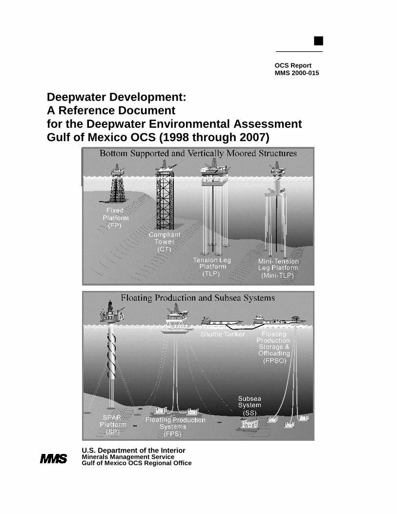
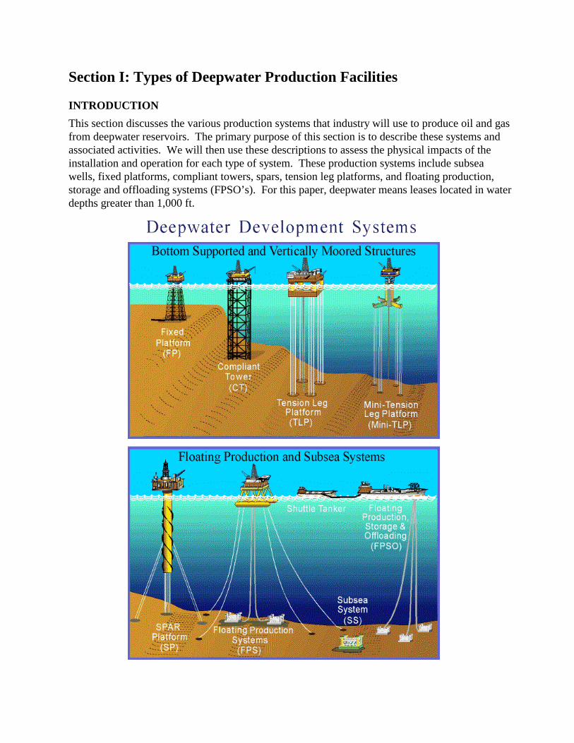
This section discusses the various production systems that industry will use to produce oil and gasfrom deepwater reservoirs. The primary purpose of this section is to describe these systems andassociated activities. We will then use these descriptions to assess the physical impacts of theinstallation and operation for each type of system. These production systems include subseawells, fixed platforms, compliant towers, spars, tension leg platforms, and floating production,storage and offloading systems (FPSO’s). For this paper, deepwater means leases located in waterdepths greater than 1,000 ft.
6
We have written a chapter addressing each system as follows:— overview,— technical descriptions,— process descriptions including installation, maintenance, and operation activities.
The FPSO Chapter is more detailed than the others because none have been installed in the Gulfof Mexico (OCS). It was felt that a more detailed understanding of the system’s capabilities andinterfaces with the environment was needed.
We also discuss the installation and operation of a fixed platform installed in deepwater. Industryhas installed several steel jacket platforms in water depths greater than 1,000 ft; however, theprimary purpose for describing fixed platforms is to show the similarities of deepwater productionoperations to shallow-water operations. For example, production treatment equipment used ondeepwater facilities will be similar to the equipment used for shelf operations.
Where possible, we discuss maximum and minimum sizes of a system or component. We also tryto identify activities that would have possible seafloor, water, and air impacts. For example, weinclude the type, size, number, and duration of vessels that supported the installation andoperation of a system. We gathered this data from existing and planned facilities.
7
Chapter 1: SUBSEA SYSTEMS
OVERVIEW
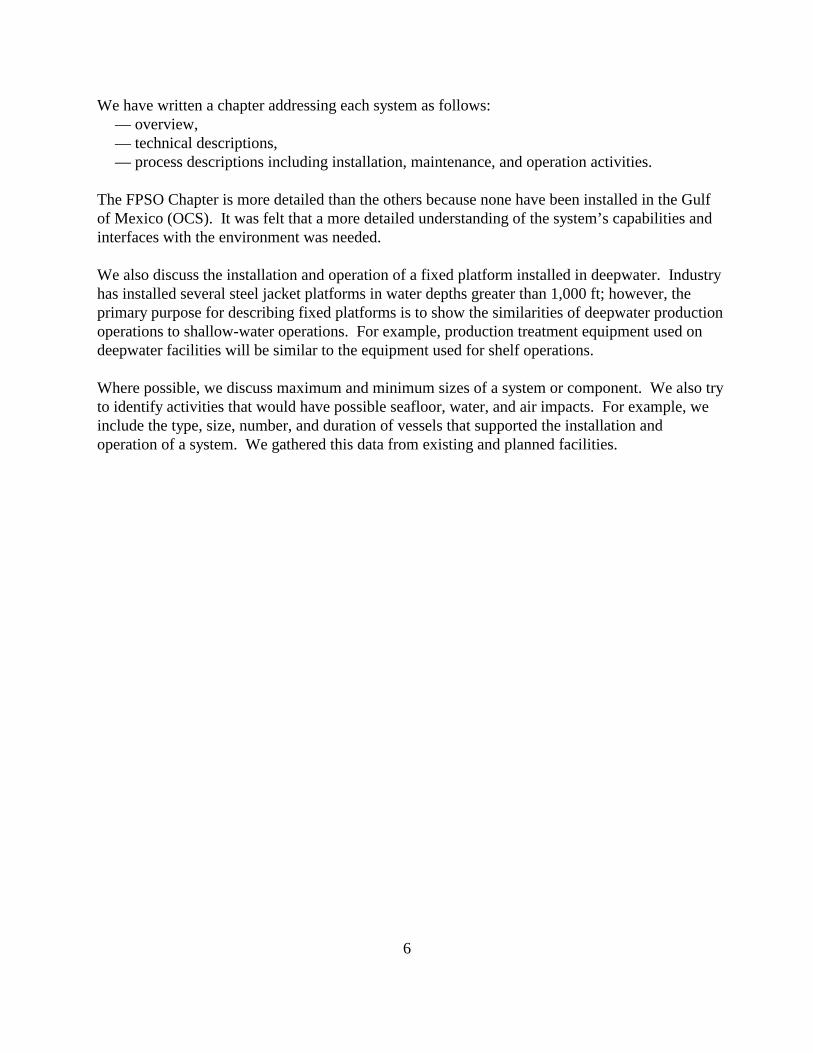
Subsea systems are generally multicomponent seafloor systems that allow for the production ofhydrocarbons in water depths that would normally rule out installing conventional fixed or bottom-founded platforms. Through an array of subsea wells, manifolds, central umbilicals, and flowlines(all described below), a subsea system can be located many miles away in deeper water and tiedback to existing host facilities in shallow water. Host facilities in deeper water would likely be oneof several types of floating production systems. Figure 1.1 shows different arrangements of thesubsea system components, which can be described as
— Single-well satellite; — Template;— Multiwell satellite; — Combination of the above.— Cluster-well system;
T o H o s t T o H o s t T o H o s t T o H o s t
Single Multi Cluster Template
Figure 1.1: Various layouts of the subsea components.
TECHNICAL DESCRIPTIONS
This section describes each of the major components of the subseaproduction system in terms of the typical or in range of sizes andarrangements.
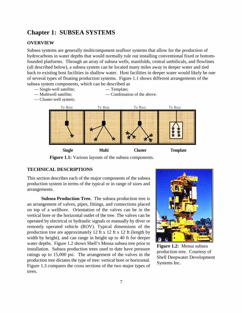
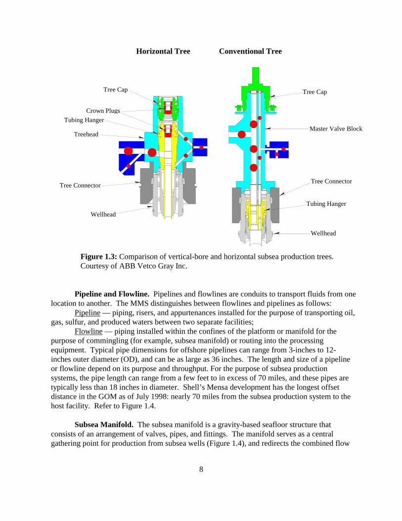
Subsea Production Tree. The subsea production tree isan arrangement of valves, pipes, fittings, and connections placedon top of a wellbore. Orientation of the valves can be in thevertical bore or the horizontal outlet of the tree. The valves can beoperated by electrical or hydraulic signals or manually by diver orremotely operated vehicle (ROV). Typical dimensions of theproduction tree are approximately 12 ft x 12 ft x 12 ft (length bywidth by height), and can range in height up to 40 ft for deeperwater depths. Figure 1.2 shows Shell’s Mensa subsea tree prior toinstallation. Subsea production trees used to date have pressureratings up to 15,000 psi. The arrangement of the valves in theproduction tree dictates the type of tree: vertical bore or horizontal.Figure 1.3 compares the cross sections of the two major types oftrees.
Figure 1.2: Mensa subseaproduction tree. Courtesy ofShell Deepwater DevelopmentSystems Inc.
8
.
Figure 1.3: Comparison of vertical-bore and horizontal subsea production trees.Courtesy of ABB Vetco Gray Inc.
Pipeline and Flowline. Pipelines and flowlines are conduits to transport fluids from onelocation to another. The MMS distinguishes between flowlines and pipelines as follows:
Pipeline — piping, risers, and appurtenances installed for the purpose of transporting oil,gas, sulfur, and produced waters between two separate facilities;
Flowline — piping installed within the confines of the platform or manifold for thepurpose of commingling (for example, subsea manifold) or routing into the processingequipment. Typical pipe dimensions for offshore pipelines can range from 3-inches to 12-inches outer diameter (OD), and can be as large as 36 inches. The length and size of a pipelineor flowline depend on its purpose and throughput. For the purpose of subsea productionsystems, the pipe length can range from a few feet to in excess of 70 miles, and these pipes aretypically less than 18 inches in diameter. Shell’s Mensa development has the longest offsetdistance in the GOM as of July 1998: nearly 70 miles from the subsea production system to thehost facility. Refer to Figure 1.4.
Subsea Manifold. The subsea manifold is a gravity-based seafloor structure thatconsists of an arrangement of valves, pipes, and fittings. The manifold serves as a centralgathering point for production from subsea wells (Figure 1.4), and redirects the combined flow
Horizontal Tree Conventional Tree
Tree Cap
Crown Plugs
Tubing Hanger
Treehead
Tree Connector
Wellhead
Tree Cap
Master Valve Block
Tree Connector
Tubing Hanger
Wellhead
9
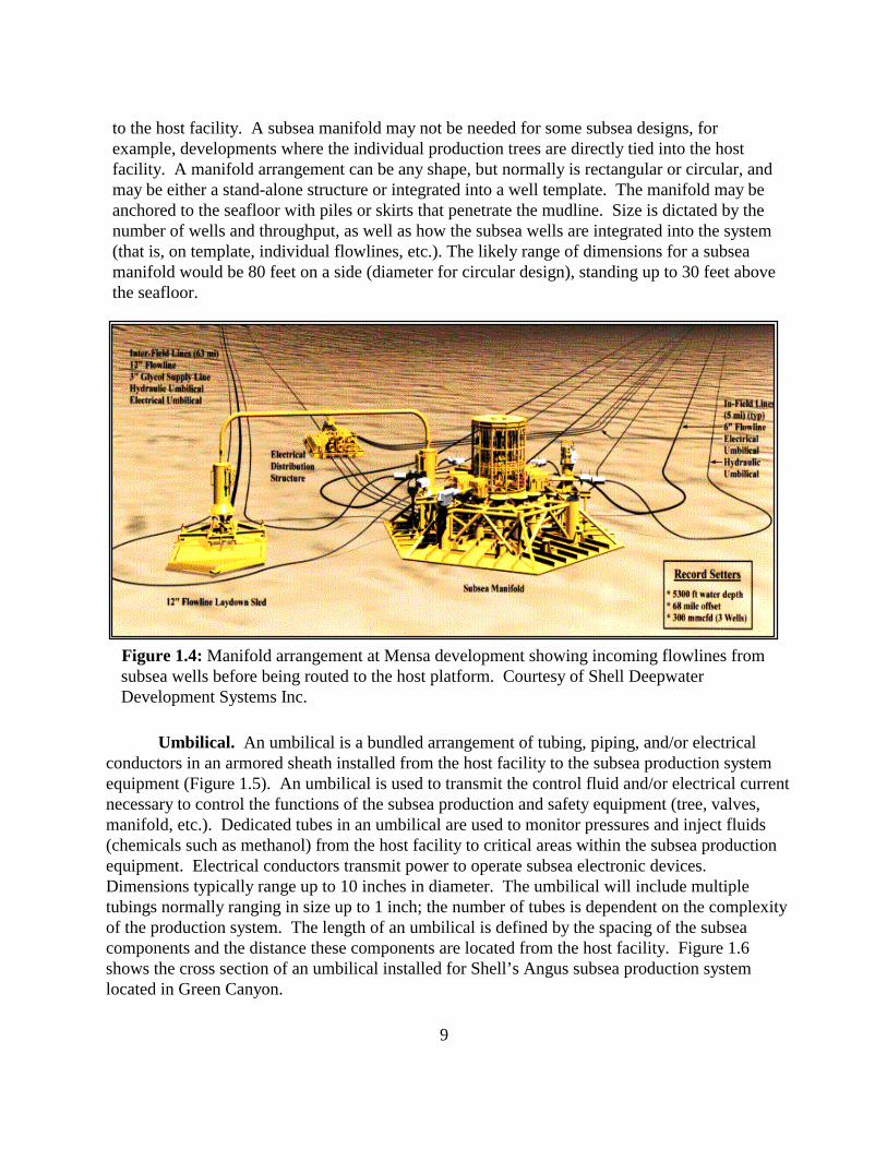
to the host facility. A subsea manifold may not be needed for some subsea designs, forexample, developments where the individual production trees are directly tied into the hostfacility. A manifold arrangement can be any shape, but normally is rectangular or circular, andmay be either a stand-alone structure or integrated into a well template. The manifold may beanchored to the seafloor with piles or skirts that penetrate the mudline. Size is dictated by thenumber of wells and throughput, as well as how the subsea wells are integrated into the system(that is, on template, individual flowlines, etc.). The likely range of dimensions for a subseamanifold would be 80 feet on a side (diameter for circular design), standing up to 30 feet abovethe seafloor.
Figure 1.4: Manifold arrangement at Mensa development showing incoming flowlines from subsea wells before being routed to the host platform. Courtesy of Shell Deepwater Development Systems Inc.
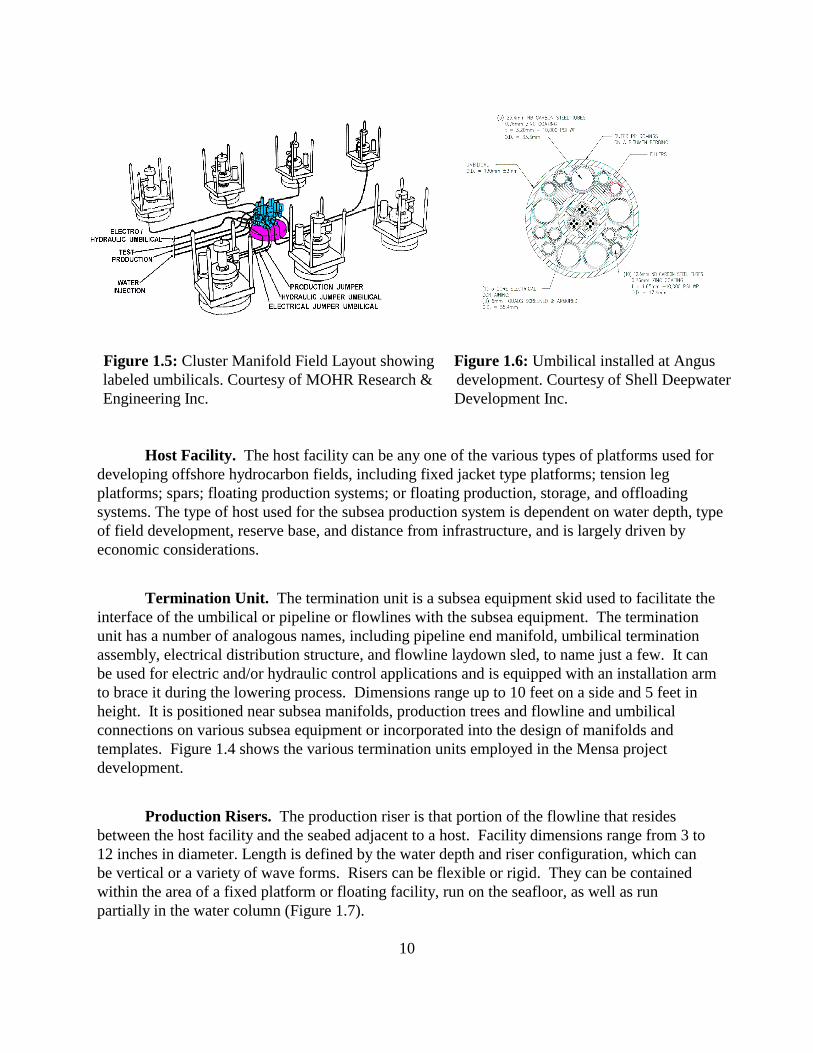
Umbilical. An umbilical is a bundled arrangement of tubing, piping, and/or electricalconductors in an armored sheath installed from the host facility to the subsea production systemequipment (Figure 1.5). An umbilical is used to transmit the control fluid and/or electrical currentnecessary to control the functions of the subsea production and safety equipment (tree, valves,manifold, etc.). Dedicated tubes in an umbilical are used to monitor pressures and inject fluids(chemicals such as methanol) from the host facility to critical areas within the subsea productionequipment. Electrical conductors transmit power to operate subsea electronic devices. Dimensions typically range up to 10 inches in diameter. The umbilical will include multipletubings normally ranging in size up to 1 inch; the number of tubes is dependent on the complexityof the production system. The length of an umbilical is defined by the spacing of the subseacomponents and the distance these components are located from the host facility. Figure 1.6shows the cross section of an umbilical installed for Shell’s Angus subsea production systemlocated in Green Canyon.
10
Figure 1.5: Cluster Manifold Field Layout showing Figure 1.6: Umbilical installed at Anguslabeled umbilicals. Courtesy of MOHR Research & development. Courtesy of Shell DeepwaterEngineering Inc. Development Inc.
Host Facility. The host facility can be any one of the various types of platforms used fordeveloping offshore hydrocarbon fields, including fixed jacket type platforms; tension legplatforms; spars; floating production systems; or floating production, storage, and offloadingsystems. The type of host used for the subsea production system is dependent on water depth, typeof field development, reserve base, and distance from infrastructure, and is largely driven byeconomic considerations.
Termination Unit. The termination unit is a subsea equipment skid used to facilitate theinterface of the umbilical or pipeline or flowlines with the subsea equipment. The terminationunit has a number of analogous names, including pipeline end manifold, umbilical terminationassembly, electrical distribution structure, and flowline laydown sled, to name just a few. It canbe used for electric and/or hydraulic control applications and is equipped with an installation armto brace it during the lowering process. Dimensions range up to 10 feet on a side and 5 feet inheight. It is positioned near subsea manifolds, production trees and flowline and umbilicalconnections on various subsea equipment or incorporated into the design of manifolds andtemplates. Figure 1.4 shows the various termination units employed in the Mensa projectdevelopment.
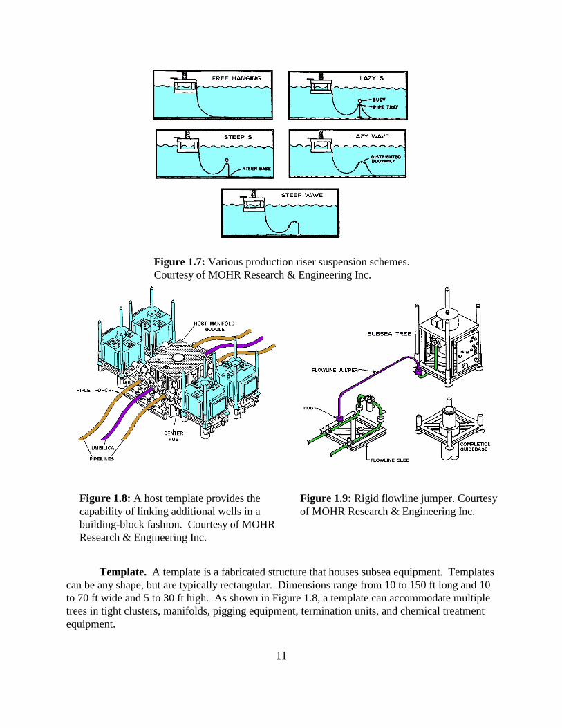
Production Risers. The production riser is that portion of the flowline that residesbetween the host facility and the seabed adjacent to a host. Facility dimensions range from 3 to12 inches in diameter. Length is defined by the water depth and riser configuration, which canbe vertical or a variety of wave forms. Risers can be flexible or rigid. They can be containedwithin the area of a fixed platform or floating facility, run on the seafloor, as well as runpartially in the water column (Figure 1.7).
11
Figure 1.7: Various production riser suspension schemes. Courtesy of MOHR Research & Engineering Inc.
Figure 1.8: A host template provides the Figure 1.9: Rigid flowline jumper. Courtesycapability of linking additional wells in a of MOHR Research & Engineering Inc.building-block fashion. Courtesy of MOHRResearch & Engineering Inc.
Template. A template is a fabricated structure that houses subsea equipment. Templatescan be any shape, but are typically rectangular. Dimensions range from 10 to 150 ft long and 10to 70 ft wide and 5 to 30 ft high. As shown in Figure 1.8, a template can accommodate multipletrees in tight clusters, manifolds, pigging equipment, termination units, and chemical treatmentequipment.
-12-
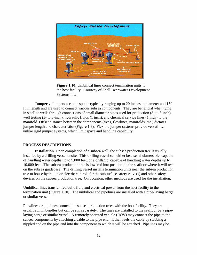
Figure 1.10: Umbilical lines connect termination units tothe host facility. Courtesy of Shell Deepwater DevelopmentSystems Inc.
Jumpers. Jumpers are pipe spools typically ranging up to 20 inches in diameter and 150ft in length and are used to connect various subsea components. They are beneficial when tyingin satellite wells through connections of small diameter pipes used for production (3- to 6-inch),well testing (3- to 6-inch), hydraulic fluids (1 inch), and chemical service lines (1 inch) to themanifold. Offset distance between the components (trees, flowlines, manifolds, etc.) dictatesjumper length and characteristics (Figure 1.9). Flexible jumper systems provide versatility,unlike rigid jumper systems, which limit space and handling capability.
PROCESS DESCRIPTIONS
Installation. Upon completion of a subsea well, the subsea production tree is usuallyinstalled by a drilling vessel onsite. This drilling vessel can either be a semisubmersible, capableof handling water depths up to 5,000 feet, or a drillship, capable of handling water depths up to10,000 feet. The subsea production tree is lowered into position on the seafloor where it will reston the subsea guidebase. The drilling vessel installs termination units near the subsea productiontree to house hydraulic or electric controls for the subsurface safety valve(s) and other safetydevices on the subsea production tree. On occasion, other methods are used for the installation.
Umbilical lines transfer hydraulic fluid and electrical power from the host facility to thetermination unit (Figure 1.10). The umbilical and pipelines are installed with a pipe-laying bargeor similar vessel.
Flowlines or pipelines connect the subsea production trees with the host facility. They areusually run in bundles but can be run separately. The lines are installed to the seafloor by a pipe-laying barge or similar vessel. A remotely operated vehicle (ROV) may connect the pipe to thesubsea components by attaching a cable to the pipe end. It then reels the cable by stabbing anippled end on the pipe end into the component to which it will be attached. Pipelines may be
-13-
insulated for deepwater service because of cold water temperatures and high pressures, which cancause hydrates. Pipelines may be slightly elevated off the seafloor in an effort to cool the pipeuniformly. Before this elevated section, chemical injection may be used to minimize possiblehydrate formation.
A crane or derrick barge can install a subsea manifold from the drilling vessel with an ROValigning the manifold on the seafloor. Jumpers are installed to connect the trees and flowlineswith the manifold. Jumpers elevate the lines so a level connection can be made with themanifold. This gives the ROV accessibility to that connection. Jumpers are also installed on theexport line to the host facility for the same reason previously listed; a crane or any derrick bargecan do the installation.
If a subsea template system is used, the manifold, chemical injection equipment, subseaproduction trees, and termination units can be incorporated into the design of the template. Thedrilling vessel or derrick barge installs the template using an ROV as a guide to the seafloor.
Maintenance. After the installation of all the subsea components that were included intoa particular design, maintenance can be completed in different ways for the different components.An ROV can inspect and replace the subsea production tree. The subsea production tree can beraised to the surface using a drilling vessel. An ROV from either the drilling vessel or any workboat can inspect the flowlines, pipelines or umbilicals. If severe damage or pipe breach occurs, anew line is installed and the existing one is disconnected and either left on the bottom orretrieved. After the ROV inspects and disconnects the appropriate lines and jumpers, the drillingvessel or appropriate derrick barge brought on location retrieves the subsea manifold. Termination units are maintained in the same fashion.
If the design of the subsea system involves the use of a template, then only components in thetemplate can be retrieved. These components are the individual subsea production trees,manifold, chemical injection equipment, and termination units. The ROV completes theappropriate disconnections of the flowlines and pipelines or umbilicals, and then a crane ordrilling vessel retrieves them.
Footprint. Most of the subsea components have a height above the seafloor and may actas an obstruction. Templates can have heights up to 20 ft above the mudline and hold thegreatest risk of hanging up nets or anchors. Flowlines, pipelines and umbilicals have the leastrisk since they commonly rest on the seafloor. When the host is a fixed platform, the lines lie onthe seafloor until they travel horizontally to vertically-orientated risers within the protection ofthe jacket. This is not the case when the lines are building angle on their way back to a floatinghost facility from a manifold, tree, or termination unit. The remaining subsea component heightsfall within the lines and the template.
All of the subsea components have a seafloor footprint when designed for installation outside atemplate. Once again, the template holds the largest seafloor footprint potential (depending onthe design) and the flowlines and pipelines and umbilicals hold the least. Some of thecomponents like the template and the subsea manifold penetrate the seafloor or use gravity tosecure them. Manifolds can use skirts that extend a few feet under the mudline to help secure
-14-
themselves on mud slopes. Templates can have small diameter piles installed to securethemselves to a sloping seafloor. Subsea production trees rely on the casing and wellhead astheir securing factor. Generally, gravity is the most common method used to secure subseacomponents to the seafloor.
Leakage. Leakage can occur in any of the subsea components. In any of the lines(flowline, pipeline, umbilical), leaks in the fittings or a structural breach may be a factor. Anyconnection point on the manifold, termination unit, or jumper from the lines can be a target areafor leaks. Structural integrity would be another factor. Pressure drops may result in leaks in thelines, with ROV inspection of the lines and other components capable of visually confirming theleaks. There are safety valves at the host facility and in the production tubing beneath the subseatree that can be shut in when a leak is detected to minimize the lost fluids.
BIBLIOGRAPHY
ABB Vetco Gray, Figure 1.3, Comparison of Horizontal and Vertical-Bore Trees. Electroniccorrespondence with Jim Gariepy, December 21, 1999.
MOHR Research & Engineering Inc., Figure 1.5, Cluster Manifold with Labeled Umbilicals.Electronic correspondence with Debbie Love, September 30, 1999.
MOHR Research & Engineering Inc., Figure 1.7, Production Risers. Electronic correspondencewith Debbie Love, September 30, 1999.
MOHR Research & Engineering Inc., Figure 1.8, Subsea Template. Electronic correspondencewith Debbie Love, December 14, 1999.
MOHR Research & Engineering Inc., Figure 1.9, Rigid Jumper. Electronic correspondencewith Debbie Love, September 30, 1999.
Shell Deepwater Development Systems Inc., Figure 1.2, Mensa Tree. Electronic correspondencewith Peter Hill, October 4, 1999.
Shell Deepwater Development Systems Inc., Figure 1.4, News release entitled “Shell to SetWorld Records at Deep Water ‘Mensa’ Field.” Electronic correspondence with PeterHill, October 4, 1999.
Shell Deepwater Development Systems Inc., Figure 1.6, Umbilical Cutaway. Electroniccorrespondence with Peter Hill, October 4, 1999.
Shell Deepwater Development Systems Inc., Figure 1.10, News release entitled “Shell’s PopeyeMoving Soon to Deep Water Sea Floor.” Electronic correspondence with Peter Hill,November 4, 1999.

-15-
Chapter 2: FIXED PLATFORM
OVERVIEW
A fixed platform consists of a welded tubular steel jacket, deck, and surface facility. The jacketand deck make up the foundation for the surface facilities. Piles driven into the seafloor securethe jacket. The water depth at the intended location dictates the height of the platform. Once thejacket is secured and the deck is installed, additional modules are added for drilling, production,and crew operations. Large, barge-mounted cranes position and secure the jacket prior to theinstallation of the topsides modules. Economic considerations limit development of fixed (rigid)platforms to water depths no greater than 1,500 ft.
TECHNICAL DESCRIPTIONS
Surface Facility. Surface facilities (also known as topsides) are the part of the platformthat contains the drilling, production, and crew quarter modules. The size of each module isdictated by the volume of fluid to be handled, the number of personnel needed to operate thefacility and operations, and the potential expansion needed to accommodate future productionfrom other fields. Combined, the topsides dimensions could be 200 feet by 200 feet per decklevel, with four decks, resulting in an overall height of 100 feet.
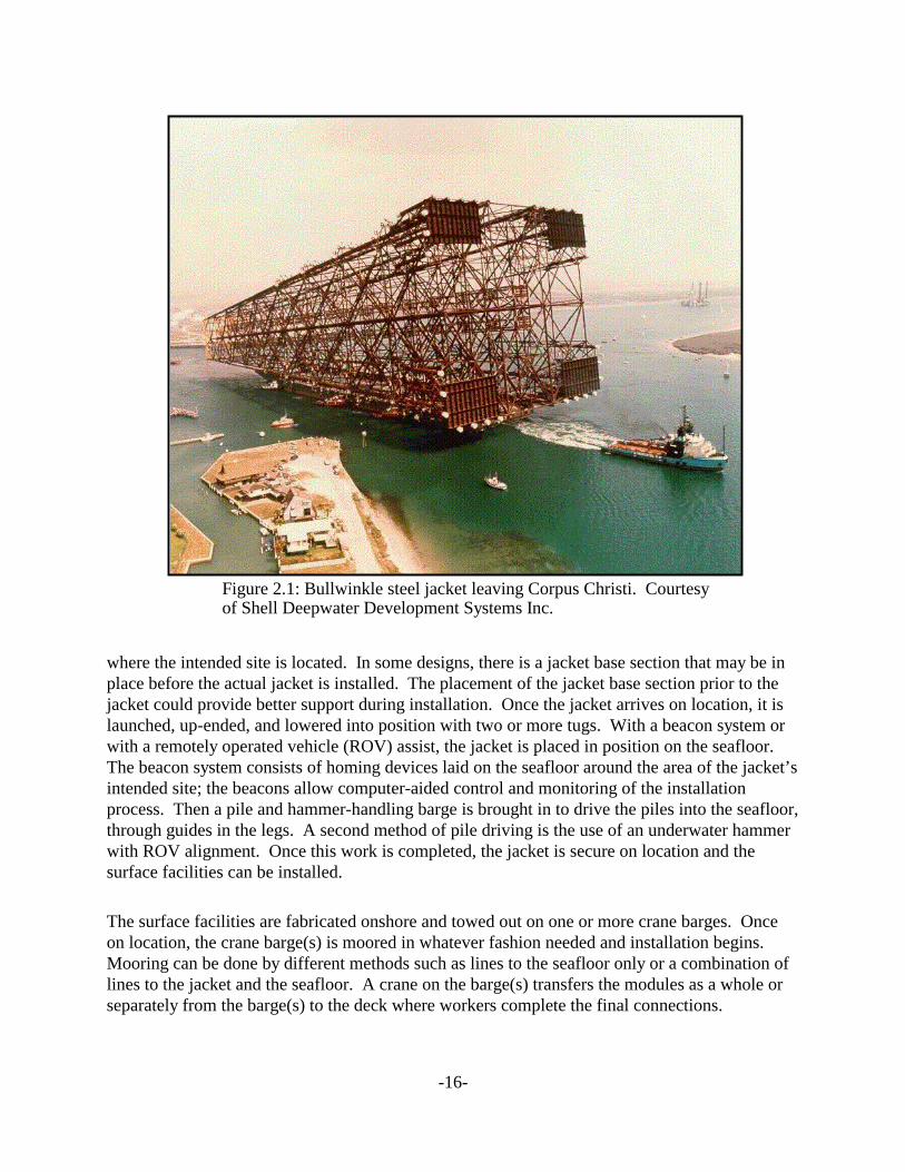
Jacket. A jacket is a tubular supporting structure for an offshore platform consisting offour, six, or eight 7- to 14-ft diameter tubulars welded together with pipe braces to form a stool-like structure. Figure 2.1 shows Shell’s Bullwinkle platform leaving Corpus Christi prior toinstallation. The jacket is secured to the seafloor by weight and 7-ft diameter piles that penetrateseveral hundreds of feet beneath the mudline. Typical base dimensions are 400 feet by 500 feet. Skirts are also added to aid the jacket in fixing it to the seafloor. At the water line, dimensionscan range up to 150 feet on a side. The water depth that the topsides will reside in normallydictates jacket height.
Pipeline. A pipeline is a system of connected lengths of pipe that transportshydrocarbons; the pipe is usually laid or buried on the seafloor by a pipe-lay barge. Pipediameters generally range from 4 to 36 inches. The pipes may be coated in concrete for weightand use some type of cathodic protection for long-term integrity. Distances between theproduction facility and its onshore destination dictate length. A full description of a pipeline canbe found in Section III on transportation options.
Support Services. Support services that make everyday operation possible includesupplies, materials, and workers that can be transported by workboats, crewboats, supply boats,and helicopters.
PROCESS DESCRIPTIONS
Installation. After the onshore fabrication of the jacket is completed, it is loaded onto avery large barge (dimensions up to 850 ft by 200 ft by 50 ft) that will transport the jacket to itslocation. The towing of the jacket may involve the use of several tugs (up to 52,000 hpcombined) over hundreds of miles, the distance determined by where the jacket is fabricated and
-16-
Figure 2.1: Bullwinkle steel jacket leaving Corpus Christi. Courtesy of Shell Deepwater Development Systems Inc.
where the intended site is located. In some designs, there is a jacket base section that may be inplace before the actual jacket is installed. The placement of the jacket base section prior to thejacket could provide better support during installation. Once the jacket arrives on location, it islaunched, up-ended, and lowered into position with two or more tugs. With a beacon system orwith a remotely operated vehicle (ROV) assist, the jacket is placed in position on the seafloor. The beacon system consists of homing devices laid on the seafloor around the area of the jacket’sintended site; the beacons allow computer-aided control and monitoring of the installationprocess. Then a pile and hammer-handling barge is brought in to drive the piles into the seafloor,through guides in the legs. A second method of pile driving is the use of an underwater hammerwith ROV alignment. Once this work is completed, the jacket is secure on location and thesurface facilities can be installed.
The surface facilities are fabricated onshore and towed out on one or more crane barges. Onceon location, the crane barge(s) is moored in whatever fashion needed and installation begins. Mooring can be done by different methods such as lines to the seafloor only or a combination oflines to the jacket and the seafloor. A crane on the barge(s) transfers the modules as a whole orseparately from the barge(s) to the deck where workers complete the final connections.
-17-
A pipeline is connected to the jacket via a jumper at its base. A pipe-laying barge or ship installsthe pipeline over the distance needed to connect the platform to shore or another facility. Fordeepwater applications, these vessels may be dynamically positioned and do not require anymooring system.
Maintenance. The nature of a component as well as the weather dictates the extent andduration of the maintenance performed on a platform. Either divers in shallow water or an ROVin deeper water would inspect the jacket or anything inside its boundary to determine the extentof maintenance required. A crane barge would attempt any retrieval or replacement.
The crew can maintain any surface facility component, such as the drilling, production and crewquarters module, and repair it with parts brought in by workboats. If major repairs orreplacements are needed, a crane barge transfers large materials or complete modules.
The pipelines are monitored for pressure changes in the lines and through ROV inspection byvideo. If leaks are detected, repairs are begun. Clamps can be used to minimize lost fluids untila new line is laid and put on line. Pigs are pumped through sections of the pipe to clean out theinner walls, clearing them of any paraffin or hydrate coating. (Pigs are wipers that can be severalfeet long and whose cross-section equals the inner diameter of the pipeline.)
Footprint. With platforms, seafloor footprints are limited to the dimensions of the baseof the jacket and the mooring systems of crane barges and workboats. These dimensions arestated earlier in this chapter. The mooring systems of the crane barges and workboats may vary,but they commonly use the jacket structure and the seafloor for anchoring.
Operations. During normal operations of the surface facility, air emissions occur fromthe separation, compression, and cogeneration components, and from other sources. Emissionscan occur during the installation and maintenance of any of the components. The prime moversfor the drilling operations and the operational components for the living quarters also add to theair emissions. Stored chemical may spill or ignite, adding to the emissions.
Water discharges from the surface facility can occur from many sources during normaloperations. Discharges may also occur during the installation and maintenance of anycomponent. Any of the many liquid chemicals used in everyday operations have the potential ofbeing spilled. These include but are not limited to any glycol or methanol used in chemicalinjection, dispersant agents used in oil-spill response, produced waters, mud residues from therock cuttings, and cleaning agents.
From drilling operations, the cuttings account for most of the discharges. The water depthdictates the distribution of the cuttings and the concentration of the drilling mud still left on thecuttings. In deepwater, cuttings have longer distances to travel to reach the seafloor and aredistributed over a larger area. The size and type of particle, as well as the ocean currents, affectthe distribution. This disturbance is not focused in a small area as in shallow water, where pilesmay accumulate after a long time. Other impacts may include any dropped objects such as tools,spare parts, and trash.
-18-
BIBLIOGRAPHY
Shell Deepwater Development Systems Inc., Figure 2.1, Bullwinkle Steel Jacket Prior ToInstallation. Electronic correspondence with Peter Hill, December 22, 1999.
Shell Offshore Inc news release entitled, “Bullwinkle Platform Successfully Launched,”May 31, 1988.
Sterling, G.H., Shell Oil Co.; A.O.P. Casbarian, A.O.P. Casbarian & Associates; N.L. Dodge,and D.G. Godfrey, Shell Oil Co. “Construction of the Cognac Platform, 1025 Feet ofWater, Gulf of Mexico.” Copyright 1979. Paper OTC 3493 presented at the 1988Offshore Technology Conference, Houston, Texas, 2-5 May 1988.
-19-
Chapter 3: COMPLIANT TOWER
OVERVIEW
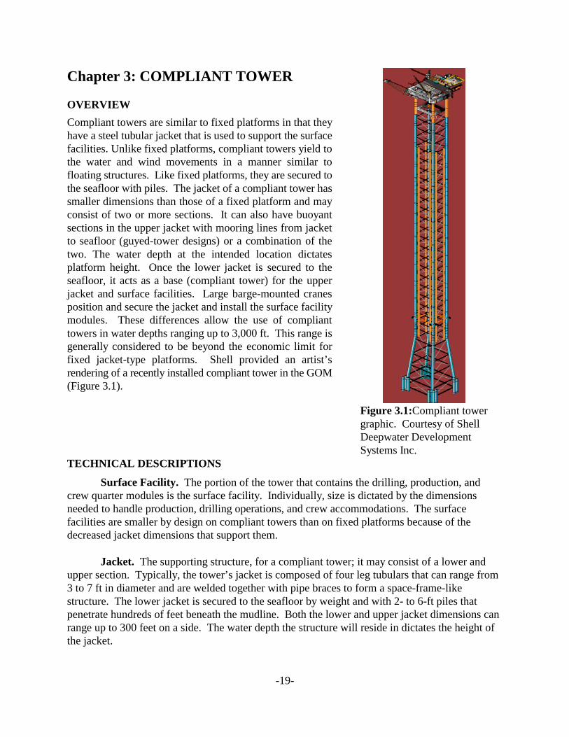
Compliant towers are similar to fixed platforms in that theyhave a steel tubular jacket that is used to support the surfacefacilities. Unlike fixed platforms, compliant towers yield tothe water and wind movements in a manner similar tofloating structures. Like fixed platforms, they are secured tothe seafloor with piles. The jacket of a compliant tower hassmaller dimensions than those of a fixed platform and mayconsist of two or more sections. It can also have buoyantsections in the upper jacket with mooring lines from jacketto seafloor (guyed-tower designs) or a combination of thetwo. The water depth at the intended location dictatesplatform height. Once the lower jacket is secured to theseafloor, it acts as a base (compliant tower) for the upperjacket and surface facilities. Large barge-mounted cranesposition and secure the jacket and install the surface facilitymodules. These differences allow the use of complianttowers in water depths ranging up to 3,000 ft. This range isgenerally considered to be beyond the economic limit forfixed jacket-type platforms. Shell provided an artist’srendering of a recently installed compliant tower in the GOM(Figure 3.1).
Figure 3.1:Compliant towergraphic. Courtesy of ShellDeepwater DevelopmentSystems Inc.
TECHNICAL DESCRIPTIONS
Surface Facility. The portion of the tower that contains the drilling, production, andcrew quarter modules is the surface facility. Individually, size is dictated by the dimensionsneeded to handle production, drilling operations, and crew accommodations. The surfacefacilities are smaller by design on compliant towers than on fixed platforms because of thedecreased jacket dimensions that support them.
Jacket. The supporting structure, for a compliant tower; it may consist of a lower andupper section. Typically, the tower’s jacket is composed of four leg tubulars that can range from3 to 7 ft in diameter and are welded together with pipe braces to form a space-frame-likestructure. The lower jacket is secured to the seafloor by weight and with 2- to 6-ft piles thatpenetrate hundreds of feet beneath the mudline. Both the lower and upper jacket dimensions canrange up to 300 feet on a side. The water depth the structure will reside in dictates the height ofthe jacket.
-20-
Buoyant System. A series of buoyant tanks (up to 12) located in the upper part of thejacket places the members in tension, reducing the foundation loads of the structure. The tankscan range up to 20 ft in diameter and up to 120 ft in length. The amount of buoyancy is computercontrolled, keeping the appropriate tension in the structure members during wind and wavemovements. This buoyant system can also be incorporated into some member designs,minimizing the size and placement of the tanks.
Mooring. For compliant towers in general, mooring is only used in the guyed-towerdesign. For guyed-towers, several mooring lines (up to 20 lines measuring 5 ½-inch dia.) areattached to the jacket close to the waterline and are spread out evenly around it (up to 4,000 ft ofline). Clump weights (120 ft x 8 ft, up to 200 tons) may be attached to each mooring line andmove as the tower moves with the wind and wave forces. To control the tower motions better,the lines are kept in tension during the swaying motions. The portion of the lines past the clumpweights are anchored into the seafloor with piles (as many as 20, each 72-inch dia., 115-ft long,penetrating 130 ft, and weighing up to 60 tons).
Pipeline. A system of connected lengths of pipe that transports hydrocarbons. Apipe-lay barge usually lays or buries them on the seafloor. Pipe diameters generally range up to36 inches. They may be coated in concrete or use some type of cathodic protection for long-termintegrity. Distances between the production facility and its onshore destination dictate pipelinelength. A full description of pipelines can be found in the transportation options section (SectionIII).
Support Services. Support Services that make everyday operations possible includesupplies, materials, and workers, which can be transported by workboats, crewboats, supplyboats, and helicopters.
PROCESS DESCRIPTIONS
Installation. During the onshore fabrication of the jacket, the mooring system for theguyed-tower is installed. A specially designed, dynamically positioned crane barge that consistsof a 100-foot crane, guyline winch module, anchor pile module, and clump weight module can beused to install the compliant tower. The installation procedure starts with the anchor piles, thenthe chains, then the clump weights, and finally the remaining mooring lines that attach to thejacket as needed. Until the jacket is installed, anchor buoys hold the remaining lines in position.
After onshore fabrication, the jacket is towed in one or two pieces out to the site on a speciallydesigned barge. The process is similar to how it is done for fixed platforms, such as Shell’sCognac or Bullwinkle project. For normal compliant towers, the upper and lower jacket can bejoined at sea or vertically joined at the site. For the guyed-tower design, the jacket is in one pieceand does not need joining. The jacket can be launched from the rear or side of the barge. Forcompliant towers, up to 10,000 hp per jacket section (upper and lower) may be needed. A seriesof tugs with a combined horsepower of up to 25,000 hp can be used to tow guyed-towers. The
-21-
design of the compliant tower and whether the jacket is in one or two pieces dictate the numberof tugs needed. One or two dynamically positioned crane barges (up to 2,000 tons) are used toinstall the jacket as a whole (guyed-towers) or join them vertically onsite or at sea.
After the jacket is installed, a deck barge brings the surface facilities out from shore to the siteand installs them either module by module or as a complete unit. The crane barge can be mooredto the jacket or to the seafloor with up to 12 lines. The twelve-point layout is most commonlyutilized.
A dynamically positioned pipe-laying ship installs the pipeline or pipeline bundle. Since thedynamic-positioned system eliminates the need for anchors, the ship can operate in and aroundcompliant towers having mooring systems without interfering with the guylines or mooring ofthe crane barges. The complete installation process can take up to eight months before anyadditional drilling or production can start.
Maintenance. Maintenance of compliant towers is completed in a method similar to thatof a fixed platform. Considerations in the guyed-tower design for the mooring system must beaddressed when any maintenance vessels are moved. The installed component and the weatherconditions dictate the extent and duration of the maintenance needed. A remotely operatedvehicle (ROV) would do any anticipated maintenance of the jacket and would inspect anythingwithin the boundary of the jacket (buoyancy tanks, risers etc.) and the mooring system (in guyed-tower design). A crane barge would complete any retrieval or replacement.
The crew can maintain any surface facility component such as the drilling, production, and crewquarters modules and repair them with parts brought in by workboats. If major repairs orreplacements are needed, a crane barge would transfer the needed large materials or completemodules.
Monitoring of the pipelines is accomplished by ROV inspection and watching for signs ofpressure drops or increased fluid volumes. If leaks are detected, clamps can be used to minimizelost fluids until a new line is laid and put on line. Pigs are pumped through sections of the pipeto clean out the inner walls, clearing them of any paraffin or hydrate coating. (Pigs are wipersthat are normally a few feet long and whose cross-section equals the inner diameter of thepipeline.)
Footprint. In compliant towers, the seafloor footprint is the base-structure dimensionmooring system of the tower (if guyed-tower design) and the mooring systems of crane bargesand workboats. Base dimensions can range up to 300 feet on a side. The mooring systems of thecrane barges and workboats may vary, but they commonly use the jacket structure and theseafloor for anchoring.
Operations. Operations are similar to those of fixed platforms but differ mainly in sizeand quantity. During normal operations of the surface facility, air emissions from the separation,compression, and cogeneration components apply. The prime movers for the drilling operationsand the operational components for the living quarters also add to the air emissions. Storedchemicals may spill or ignite, adding to the emissions.
-22-
Water discharges from the surface facility can occur from many sources during normaloperations. Discharges may also occur during the installation and maintenance of anycomponent. Any of the many liquid chemicals used in everyday operations have the potential ofbeing spilled. These include but are not limited to any glycol or methanol used in chemicalinjection, dispersant agents used in oil-spill response, produced waters, mud residue from therock cuttings, and cleaning agents.
From the drilling operations, the cuttings account for most of the depositing. The distribution ofthe cuttings and the concentration of the drilling mud still left on the cuttings are dictated by thewater depth and current. In deepwater, cuttings have longer distances to travel to reach theseafloor and create larger arrays of disturbance. These cuttings are not focused in a small area asin shallow water, where piles of cuttings may accumulate over a long time. Other impacts mayinclude any dropped objects such as tools, spare parts, and trash.
BIBLIOGRAPHY
Boening, D.E. and E.R. Howell, Exxon Co. U.S.A. “Lena Guyed Tower Project Overview.”Copyright 1984. Paper OTC 4649 presented at the 1984 Offshore TechnologyConference, Houston, Texas, 7-9 May 1984.
Brown, C.P. and L.M. Fontenette, Exxon Co. U.S.A.; P.G.S. Dove, Brown & Root Inc. “Installation of Guying System – Lena Guyed Tower.” Copyright 1984. Paper OTC4682 presented at the 1984 Offshore Technology Conference, Houston, Texas, 7-9 May1984.
Dearing, B.W., M.W. Lucas, and C.K. Snell, Brown & Root Inc. “The Design and Developmentof Loadout Procedures for the Lena Guyed Tower.” Copyright 1985. Paper OTC 5046presented at the 1985 Offshore Technology Conference, Houston, Texas, 6-9 May 1985.
Flood, J.K. and P.Q. Pichini, Exxon Co. U.S.A.; M.A. Danaczko, Exxon Production ResearchCo.; W.L. Greiner, Brown & Root Inc. “Side Launch of the Lena Guyed Tower Jacket.”Copyright 1984. Paper OTC 4652 presented at the 1984 Offshore TechnologyConference, Houston, Texas, 7-9 May 1984.
Glasscock, M.S. and J.W. Turner, Exxon Co. U.S.A.; L.D. Finn and P.J. Pike, ExxonProduction Research Co. “Design of the Lena Guyed Tower.” Copyright 1984. PaperOTC 4650 presented at the 1984 Offshore Technology Conference, Houston, Texas,7-9 May 1984.
Parnell Jr, R.E. and R.J. Houghton, Exxon Co. U.S.A.; J.D. McClellan, Brown & Root Inc.“Fabrication of the Lena Guyed Tower Jacket.” Copyright 1984. Paper OTC 4651
-23-
presented at the 1984 Offshore Technology Conference, Houston, Texas, 7-9 May 1984.
Shell Deepwater Development System Inc., Figure 3.1, Compliant Tower Graphic. Electroniccorrespondence to Peter Hill, October 10, 1999.
Smetak, E.C., J. Lombardi, and H.J. Roussel, Exxon Co. U.S.A.; T.C. Wozniak, Brown & RootInc. “Jacket, Deck, and Pipeline Installation – Lena Guyed Tower.” Copyright 1984.Paper OTC 4683 presented at the 1984 Offshore Technology Conference, Houston,Texas, 7-9 May 1984.
Smolinski, S.L., Shell Offshore Inc.; D.G. Morrison, Shell Development Co.; D.A. Huete, ShellOffshore Inc.; P.W. Marshall, U. of Newcastle-upon-Tyne. “The Tensioned RiserCompliant Tower.” Copyright 1994. Paper OTC 7450 presented at the 1994 OffshoreTechnology Conference, Houston, Texas, 2-5 May 1994.
Will, S.A., D.E. Calkins, and D.G. Morrison, Hudson Engineering, McDermott Inc. “TheCompliant Composite Leg Platform: A New Configuration for Deepwater FixedPlatforms and Compliant Towers.” Copyright 1988. Paper OTC 5638 presented at the1988 Offshore Technology Conference, Houston, Texas, 2-5 May 1988.
-24-
Chapter 4: SPAR
OVERVIEW
A spar is a deep-draft floating caisson, which is a hollow cylindrical structure similar to a verylarge buoy. Its four major systems are hull, moorings, topsides, and risers. The spar relies on atraditional mooring system (that is, anchor-spread mooring) to maintain its position. About90 percent of the structure is underwater. Historically, spars were used as marker buoys, forgathering oceanographic data, and for oil storage. The spar design is now being used for drilling,production, or both. Figure 4.1 is an outboard and inboard profile drawing of the classic spar.
The distinguishing feature of a spar is its deep-draft hull, which produces very favorable motioncharacteristics compared to other floating concepts. Low motions and a protected centerwell alsoprovide an excellent configuration for deepwater operations.
Listed below are some spar features:
• Water depth capability has been stated by industry as ranging up to 10,000 ft• Full drilling and production capabilities• Direct, vertical access production risers (surface production trees)• Surface blowout preventer for drilling and workover operations• Steel catenary risers (import and export)• Inherently stable – center of buoyancy is located above the center of gravity• Favorable motions compared with other floating systems• Traditional construction (steel or concrete hull)• Cost insensitive to water depth• Potential oil storage• Relocation over a wide range of water depths• Conventional drilling and process components used
TECHNICAL DESCRIPTIONS
Hull. The hull is constructed by use of normal marine and shipyard fabrication methods.The number of wells, surface wellhead spacing, and facilities weight determine the size of thecenterwell and the diameter of the hull. In the classic or full cylinder hull forms, the uppersection is compartmentalized around a flooded centerwell containing the different type of risers. This section provides the buoyancy for the spar. The middle section is also flooded but can beeconomically configured for oil storage. The bottom section (keel) is compartmentalized toprovide buoyancy during transport and to contain any field-installed, fixed ballast. Approximatehull diameter for a typical GOM spar is 130 feet, with an overall height, once deployed, ofapproximately 700 feet (with 90% of the hull in the water column).

-25-
Figure 4.1: Courtesy of Spars International Inc.
-26-
Mooring. A lateral catenary system of 6 to 20 lines keeps the spar on location. Themooring lines are a combination of spiral strand wire and chain. Because of its low motions, thespar can use a taut mooring system at a reduced scope and cost compared with a full catenarysystem. Each mooring line is anchored to the seafloor with a driven or suction pile. The hull-end of the line passes through a fairlead located on the hull below the water surface, then extendsup the outside of the hull to chain jacks at the top, usually 50 ft or more in elevation. Excesschain is stored in the hull. Depending on hull size and water depth, the moorings can vary innumber up to 20 lines and contain 3,700 ft of chain and wire. Starting at the seafloor, a typicalmooring leg may consist of approximately 200-ft long, 84-inch diameter piles; 200 ft of 4¾-inchbottom chain; 2,500 ft of 4¾-inch spiral strand wire; and 1,000 ft of 4¾-inch platform chain. The footprint created by the mooring system can reach a half-mile or more in diameter measuredon centers from the hull to the anchor piles.
Topsides. The topsides configurations follow typical fixed platform design practices. The decks can accommodate a full drilling rig (3,000 hp) or a workover rig (600-1,000 hp) plusfull production equipment. Production capacities range up to 100,000 BOPD and 325 MMcfgpd.The type and scale of operation directly influence deck size. The larger topsides would beconsistent with drilling, production, processing, and quarters facilities, and could also includeremote wells/fields being tied back to the spar for processing. Total operating deck load, whichincludes facilities, contained fluids, deck structural and support steel, drilling/workover rig, andworkover variable loads, can be 6,600 tons or more. Crew quarters on a production/workoverspar may accommodate 18 workers, while a full drilling and production facility may house 100people.
Risers. There are three basic types of risers: production, drilling, and export/import.
Production – Each vertical access production riser is top tensioned with a buoyant cylinderassembly through which one or two strings of well casing are tied back and the well completed. This arrangement allows for surface trees and a surface BOP for workover.
Drilling – The drilling riser is also a top-tensioned casing with a surface drilling BOP, whichallows a platform-type rig to be used.
Export/import risers can be flexible or top-tensioned steel pipe or steel catenaries.
Production risers consist of a conventional subsea wellhead at the mudline and a tiebackconnector with a stress joint for taking the stresses associated with environmentally imposeddisplacements. The seafloor pattern (footprint) depends on the number of risers. For example, ariser pattern may consist of 16 risers in a parallel 8 by 2 pattern, on 15-ft centers within each rowand 20 ft between rows, thus having a rectangular footprint approximately 100 ft long by 20 ftwide. Other patterns (e.g., circular or square) are available. An example production riser for aspar could be either a single or dual-bore (concentric pipe) arrangement. Low motions of thespar allow the use of the economical steel catenary riser technology for subsea production trees.
-27-
PROCESS DESCRIPTIONS
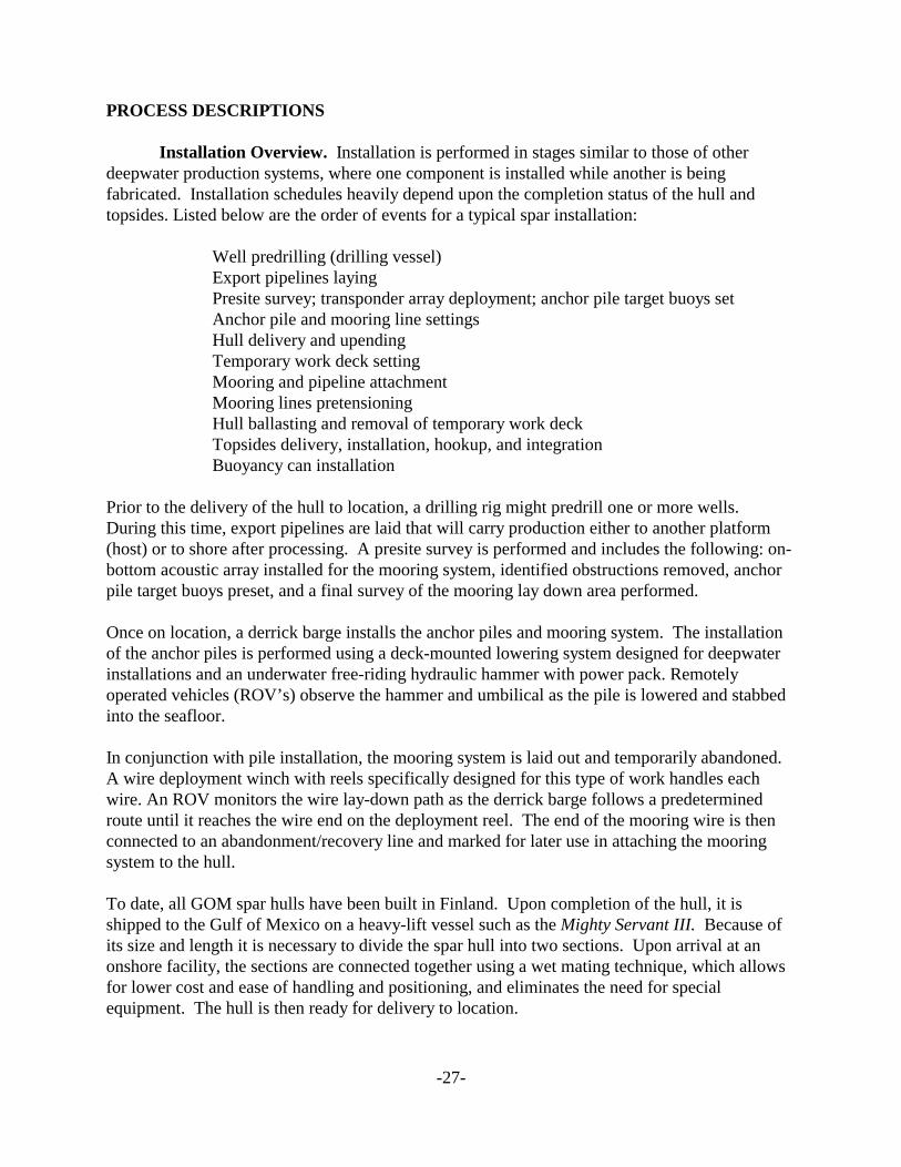
Installation Overview. Installation is performed in stages similar to those of otherdeepwater production systems, where one component is installed while another is beingfabricated. Installation schedules heavily depend upon the completion status of the hull andtopsides. Listed below are the order of events for a typical spar installation:
Well predrilling (drilling vessel)Export pipelines layingPresite survey; transponder array deployment; anchor pile target buoys setAnchor pile and mooring line settingsHull delivery and upendingTemporary work deck settingMooring and pipeline attachmentMooring lines pretensioningHull ballasting and removal of temporary work deckTopsides delivery, installation, hookup, and integrationBuoyancy can installation
Prior to the delivery of the hull to location, a drilling rig might predrill one or more wells. During this time, export pipelines are laid that will carry production either to another platform(host) or to shore after processing. A presite survey is performed and includes the following: on-bottom acoustic array installed for the mooring system, identified obstructions removed, anchorpile target buoys preset, and a final survey of the mooring lay down area performed.
Once on location, a derrick barge installs the anchor piles and mooring system. The installationof the anchor piles is performed using a deck-mounted lowering system designed for deepwaterinstallations and an underwater free-riding hydraulic hammer with power pack. Remotelyoperated vehicles (ROV’s) observe the hammer and umbilical as the pile is lowered and stabbedinto the seafloor.
In conjunction with pile installation, the mooring system is laid out and temporarily abandoned. A wire deployment winch with reels specifically designed for this type of work handles eachwire. An ROV monitors the wire lay-down path as the derrick barge follows a predeterminedroute until it reaches the wire end on the deployment reel. The end of the mooring wire is thenconnected to an abandonment/recovery line and marked for later use in attaching the mooringsystem to the hull.
To date, all GOM spar hulls have been built in Finland. Upon completion of the hull, it isshipped to the Gulf of Mexico on a heavy-lift vessel such as the Mighty Servant III. Because ofits size and length it is necessary to divide the spar hull into two sections. Upon arrival at anonshore facility, the sections are connected together using a wet mating technique, which allowsfor lower cost and ease of handling and positioning, and eliminates the need for specialequipment. The hull is then ready for delivery to location.
-28-
Depending on the proximity of the onshore assembly location to the open sea, smaller tugs(2,000 to 4,000 hp) may be used first to maneuver the hull into deeper water, and then largeroceangoing tugs (7,000 hp) tow the spar to its final destination.
A derrick barge and a pump boat await arrival of the hull on site. The barge and boat up-end thehull. While the hull is being held loosely in place, the pump boat fills the hull’s lower ballasttank and floods the centerwell. The hull self-up-ends in less than two minutes once it is flooded. Next, the derrick barge lifts into place a temporary work deck brought to the site on a materialbarge. Tasks performed using the temporary work deck are basic utility hook up, mooring lineattachment, and riser installation.
The hull is positioned on location by a tug and positioning system assistance. Then the mooringsystem is connected to the hull. After the mooring system is connected, the lines arepretensioned. Then the hull is ballasted to prepare for the topsides installation and removal ofthe temporary work deck.
Topsides are transported offshore on a material barge and lifted into place by the derrick barge. An important characteristic is that the derrick barge can perform the lift in dynamic positioningmode. The topsides consist of production facilities, drilling/workover rigs, crew living quarters,and utility decks. Installation of miscellaneous structures such as walkways, stairways, andlandings are also set in place by the derrick barge.
The last pieces of equipment to be installed are buoyancy cans and the associated stems. Thecans are simply lifted off the material barge and placed into slots inside the centerwell bay. Next,the stems are stabbed onto the cans. To prepare for riser installation, the cans are ballasted untilthe stem is at production deck level.
BIBLIOGRAPHY
Berner, P.C., K. Gendron, V.E. Baugus, and R. Young. “Neptune Project: Production RiserSystem Design and Installation.” Copyright 1997 Paper OTC 8386 presented at the 1997Offshore Technology Conference, Houston, Texas, 5-8 May 1997.
Chevron U.S.A. Production Co. “Genesis Production to Start in 1998.” North AmericanUpstream, 3 December 1997, <http://www.chevron.com/chevron_root/finance/annual-96/strat-us-up.html>.
Chevron U.S.A. Production Co. “Genesis Project Anchors Growing Chevron Commitment to‘Deepwater’ Gulf of Mexico.” Press Release, New Orleans, 19 June 1996 <http://www.chevron.com/chevron_root/newsvs/pressrel/1996/96-06-19a.html>.
-29-
Chevron U.S.A. Production Co. “Project ‘Genesis’ Begins as Chevron, Exxon, Fina Give GreenLight to New ‘Deepwater’ Project.” Press Release, New Orleans, 19 June 1996 <http:www/chevron.com/chevron_root/newsvs/pressrel/1996/96-06-19.html>.
Glanville, R.S., J.E. Halkyard, R.L. Davies, A. Steen, F. Frimm. “Neptune Project: Spar Historyand Design Considerations.” Copyright 1997 Paper OTC 8382 presented at the 1997Offshore Technology Conference, Houston, Texas, 5-8 May 1997.
J. Ray McDermott, Inc. “Hook-up and Commissioning Plan for a Gulf of Mexico 20-WellDrilling and Production Spar Platform in Green Canyon 205, 2,590’W.D. for ChevronU.S.A. Production Company.” Submitted to GOM Region Office with date 19 September1997.
J. Ray McDermott, Inc. “Installation Plan for a Gulf of Mexico 20-Well Drilling and ProductionSpar Platform in Green Canyon 205, 2,590’W.D. for Chevron U.S.A. ProductionCompany.” Submitted to GOM Region Office with date 15 May 1997.
J. Ray McDermott, Inc. Joint Ventures - Spars International, Inc. Page. 3 December 1997<http://www.jraymcdermott.com/joint/spar.html>.
J. Ray McDermott, Inc. Joint Ventures – Deep Gulf Contractors Page. 3 December 1997<http://www.jraymcdermott.com/joint/deepgulf.html>.
J. Ray McDermott, Inc. Oryx “Neptune Spar” Project Page. 3 December 1997 <http://www.jraymcdermott.com/projects/neptunep.html>.
Kuuri, J., T.J. Lehtinen, J. Miettinen. “Neptune Project: Spar Hull & Mooring System Designand Fabrication.” Copyright 1997. Paper OTC 8384 presented at the 1997 OffshoreTechnology Conference, Houston, Texas, 5-8 May 1997.
Oil Online. New Spar Contract for Aker Maritime Page. 21 October 1997<http://www.oilonline.com/news/bnsp1021.htm>.
Smith, E. and S. Davey. “Spar, Deep Draft Installations Easier With Heavy Lift Vessels.”Offshore Magazine, 57:11, 1 November 1997 http://www.ogjonline.com.
Spars International Inc., Figure 4.1, Profile Drawings of the Classic Spar. Electroniccorrespondence with Robin Converse, February 10, 2000.
-28-
Chapter 5: TENSION LEG PLATFORM
OVERVIEW
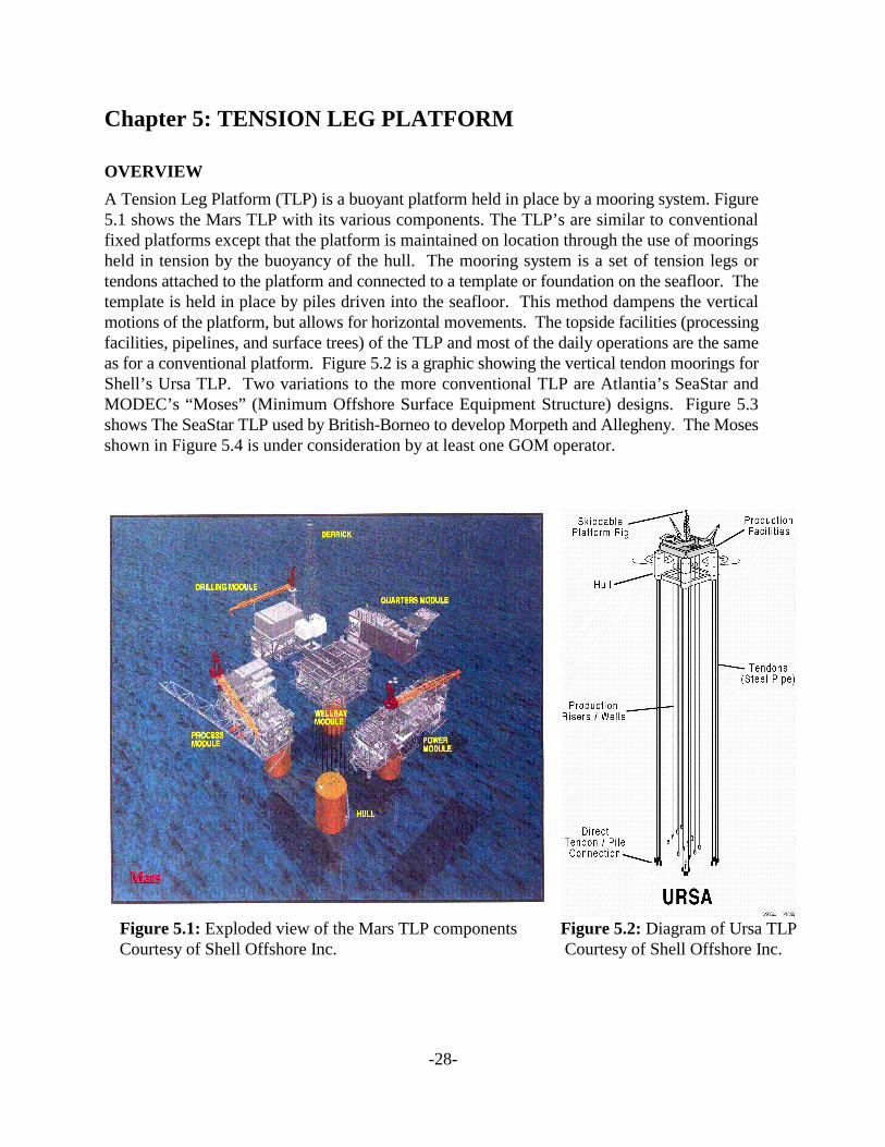
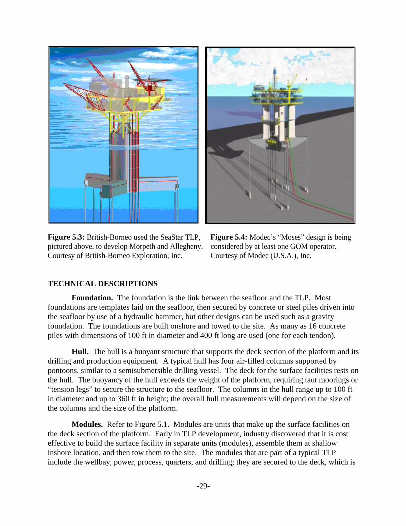
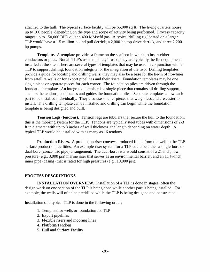
A Tension Leg Platform (TLP) is a buoyant platform held in place by a mooring system. Figure5.1 shows the Mars TLP with its various components. The TLP’s are similar to conventionalfixed platforms except that the platform is maintained on location through the use of mooringsheld in tension by the buoyancy of the hull. The mooring system is a set of tension legs ortendons attached to the platform and connected to a template or foundation on the seafloor. Thetemplate is held in place by piles driven into the seafloor. This method dampens the verticalmotions of the platform, but allows for horizontal movements. The topside facilities (processingfacilities, pipelines, and surface trees) of the TLP and most of the daily operations are the sameas for a conventional platform. Figure 5.2 is a graphic showing the vertical tendon moorings forShell’s Ursa TLP. Two variations to the more conventional TLP are Atlantia’s SeaStar andMODEC’s “Moses” (Minimum Offshore Surface Equipment Structure) designs. Figure 5.3shows The SeaStar TLP used by British-Borneo to develop Morpeth and Allegheny. The Mosesshown in Figure 5.4 is under consideration by at least one GOM operator.
Figure 5.1: Exploded view of the Mars TLP components Figure 5.2: Diagram of Ursa TLP Courtesy of Shell Offshore Inc. Courtesy of Shell Offshore Inc.
-29-
Figure 5.3: British-Borneo used the SeaStar TLP, Figure 5.4: Modec’s “Moses” design is beingpictured above, to develop Morpeth and Allegheny. considered by at least one GOM operator.Courtesy of British-Borneo Exploration, Inc. Courtesy of Modec (U.S.A.), Inc.
TECHNICAL DESCRIPTIONS
Foundation. The foundation is the link between the seafloor and the TLP. Mostfoundations are templates laid on the seafloor, then secured by concrete or steel piles driven intothe seafloor by use of a hydraulic hammer, but other designs can be used such as a gravityfoundation. The foundations are built onshore and towed to the site. As many as 16 concretepiles with dimensions of 100 ft in diameter and 400 ft long are used (one for each tendon).
Hull. The hull is a buoyant structure that supports the deck section of the platform and itsdrilling and production equipment. A typical hull has four air-filled columns supported bypontoons, similar to a semisubmersible drilling vessel. The deck for the surface facilities rests onthe hull. The buoyancy of the hull exceeds the weight of the platform, requiring taut moorings or“tension legs” to secure the structure to the seafloor. The columns in the hull range up to 100 ftin diameter and up to 360 ft in height; the overall hull measurements will depend on the size ofthe columns and the size of the platform.
Modules. Refer to Figure 5.1. Modules are units that make up the surface facilities onthe deck section of the platform. Early in TLP development, industry discovered that it is costeffective to build the surface facility in separate units (modules), assemble them at shallowinshore location, and then tow them to the site. The modules that are part of a typical TLPinclude the wellbay, power, process, quarters, and drilling; they are secured to the deck, which is
-30-
attached to the hull. The typical surface facility will be 65,000 sq ft. The living quarters houseup to 100 people, depending on the type and scope of activity being performed. Process capacityranges up to 150,000 BPD oil and 400 MMscfd gas. A typical drilling rig located on a largerTLP would have a 1.5 million-pound pull derrick, a 2,000-hp top-drive derrick, and three 2,200-hp pumps.
Template. A template provides a frame on the seafloor in which to insert eitherconductors or piles. Not all TLP’s use templates; if used, they are typically the first equipmentinstalled at the site. There are several types of templates that may be used in conjunction with aTLP to support drilling, foundation integrity, or the integration of the two. Drilling templatesprovide a guide for locating and drilling wells; they may also be a base for the tie-in of flowlinesfrom satellite wells or for export pipelines and their risers. Foundation templates may be onesingle piece or separate pieces for each corner. The foundation piles are driven through thefoundation template. An integrated template is a single piece that contains all drilling support,anchors the tendons, and locates and guides the foundation piles. Separate templates allow eachpart to be installed individually. They also use smaller pieces that weigh less and are easier toinstall. The drilling template can be installed and drilling can begin while the foundationtemplate is being designed and built.
Tension Legs (tendons). Tension legs are tubulars that secure the hull to the foundation;this is the mooring system for the TLP. Tendons are typically steel tubes with dimensions of 2-3ft in diameter with up to 3 inches of wall thickness, the length depending on water depth. Atypical TLP would be installed with as many as 16 tendons.
Production Risers. A production riser conveys produced fluids from the well to the TLPsurface production facilities. An example riser system for a TLP could be either a single-bore ordual-bore (concentric pipe) arrangement. The dual-bore riser would consist of a 21-inch, lowpressure (e.g., 3,000 psi) marine riser that serves as an environmental barrier, and an 11 ¾-inchinner pipe (casing) that is rated for high pressures (e.g., 10,000 psi).
PROCESS DESCRIPTIONS
INSTALLATION OVERVIEW. Installation of a TLP is done in stages; often thedesign work on one section of the TLP is being done while another part is being installed. Forexample, the wells will often be predrilled while the TLP is being designed and constructed.
Installation of a typical TLP is done in the following order:
1. Template for wells or foundation for TLP2. Export pipelines3. Flexible risers and mooring lines4. Platform/Tendons5. Hull and Surface Facility
-31-
Template and Foundations
Templates. Templates provide the layout for well locations and/or for the foundation, ifneeded. The wells may be drilled to their total depth, or partially drilled and the conductorcasing set. Additional well drilling and completion operations can be done from the TLP.
Template installation for drilling and foundation templates is similar, except some of theequipment used may be different. The template is built onshore and towed to location forinstallation. A drilling rig (mobile offshore drilling unit [MODU]) is preferred for installationbecause it eliminates the need for additional vessels. However, drilling rigs cannot lift largepayloads and have limited lowering capacity. Large templates may need a crane for installation;they will also require costly handling systems and rigging.
Foundations. Foundations secure the TLP to the seafloor by use of buried piles, whichcan be concrete or steel. Tendons are attached to the foundation and the platform is attached tothe tendons. The piles can either be driven or drilled and grouted. Driven piles are expensive toinstall, but the holding power of drilled and grouted piles may not be as strong because ofchanges to the sole-pile interface during the jetting and drilling operations. A typical vessel usedfor foundation installation would be one of the several available semisubmersibleconstruction/crane vessels. A hydraulic hammer is used to drive the piles into the seafloor.
Export Pipelines. Pipelines for the TLP are the same as pipelines used for conventionalplatforms. A steel catenary riser may be used to connect the subsea pipeline to the TLP. Variousmethods of installation can be used. The most common method used for installing pipelines isthe J-lay method. Pipelines for TLP’s range in size up to 18 inches in diameter for oil andapproximately 14 inches for gas. Often the pipeline will join another system for transport toshore. Oil can be transported by tanker as an alternative to pipelines.
Platform/Tendons. The TLP’s use tendons to secure the platform to the foundations. There is no set order for installation of the platform and tendons. In some cases the tendons willbe connected to the foundations, and then the platform will be moved into place and the tendonssecured to the platform. Other operations will move the platform in place first, secure thetendons to the platform, and then attach the tendons to the foundation. Another option is tosecure some of the tendons to the foundations, move the platform in place, attach the securedtendons, and attach the remaining tendons to the TLP and then to the foundation.
Hull and Surface Facility. The upper section of a TLP consists of the hull, the deck,and the surface facilities. The surface facility modules are built onshore and typically assembledat a shallow-water location near shore, then towed to the site. The modules may be attached tothe hull either inshore or at the site. Economics are the determining factor for where the modulesand hull are assembled.
The hull provides the buoyancy for the TLP to float in the water and supports the platform. Thehull contains several of the mechanical systems needed for platform operation. Topsides-relatedequipment includes firewater, seawater, diesel storage, low toxic oil storage, and completionfluid storage systems. Hull-related equipment includes ballasting and trim, drain and bilge
-32-
systems including emergency drain, HVAC, and utility systems.A typical hull has four columns, ranging in size up to 100 ft in diameter, and connected at thebase by four rectangular pontoons. The pontoons are flooded during inshore construction,module mating, and TLP installation. Deballasting is done through pumps located in thecaissons. During normal operations, the pontoons are dry.
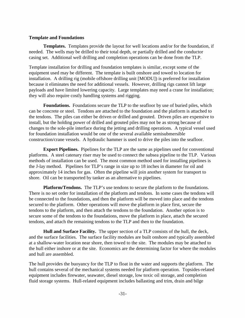
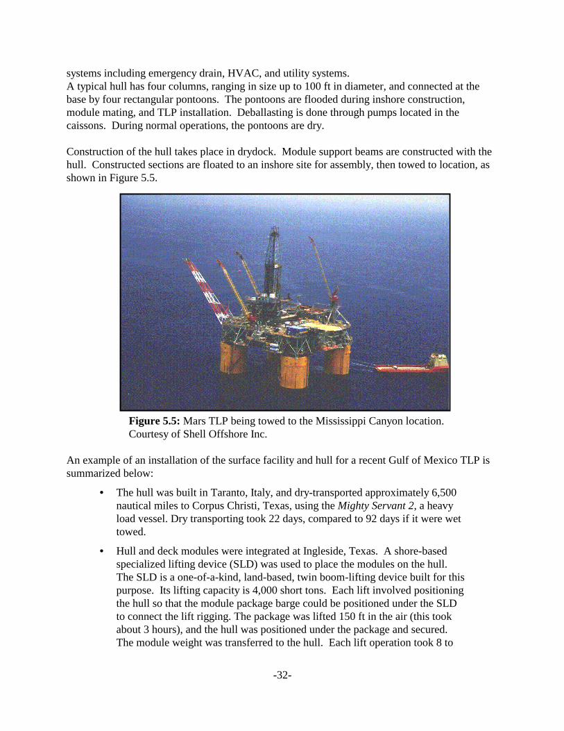
Construction of the hull takes place in drydock. Module support beams are constructed with thehull. Constructed sections are floated to an inshore site for assembly, then towed to location, asshown in Figure 5.5.
Figure 5.5: Mars TLP being towed to the Mississippi Canyon location. Courtesy of Shell Offshore Inc.
An example of an installation of the surface facility and hull for a recent Gulf of Mexico TLP issummarized below:
• The hull was built in Taranto, Italy, and dry-transported approximately 6,500nautical miles to Corpus Christi, Texas, using the Mighty Servant 2, a heavyload vessel. Dry transporting took 22 days, compared to 92 days if it were wettowed.
• Hull and deck modules were integrated at Ingleside, Texas. A shore-basedspecialized lifting device (SLD) was used to place the modules on the hull. The SLD is a one-of-a-kind, land-based, twin boom-lifting device built for thispurpose. Its lifting capacity is 4,000 short tons. Each lift involved positioningthe hull so that the module package barge could be positioned under the SLDto connect the lift rigging. The package was lifted 150 ft in the air (this tookabout 3 hours), and the hull was positioned under the package and secured. The module weight was transferred to the hull. Each lift operation took 8 to
-33-
12 hours.• The platform was then transported to the site using four ocean-going tugboats,
traveling at three miles per hour, taking seven days for the 400-mile transport.• Because the installation took place inshore there was no need for extra
helicopters, supply boats, and marine equipment, and offshore operations,quartering, and weather delays were greatly reduced. Peak manpower usedduring installation was 350 people.
Drilling Information. Well drilling for the TLP often begins after well templateinstallation. A TLP can have 50 well slots with provisions for satellite subsea well tiebacks. Predrilling involves using a mobile offshore drilling unit (drillship or semisubmersible) to batchdrill and case the wells to a convenient depth, normally through the shallow water flow zone orother potential hazard. Predrilling may also be suspended just above the production zone. Somewells may be drilled to total depth and completed. The Sonat George Richardsonsemisubmersible drilling vessel is an example of the type of vessel used to predrill.
BIBLIOGRAPHY
Balint, S.W., J.J. Kenney, B.H. Miller, L.R. Resweber, and P.L. Smith, Shell DeepwaterDevelopment Inc.; R.W. Marshall, BP Exploration Inc.; and B. Biello, Belleli SpA.“Simplification and Cycle Time Reduction – Design and Construction of the Mars TLPHull.” Copyright 1997. Paper OTC 8371 presented at the 1997 Offshore TechnologyConference, Houston, Texas, 5-8 May 1997.
Botros, F.R., T.J. Wilson, and C.M. Johnson, Conoco Inc. “The Heidrun Field: Global StructuralDesign and Analysis of the Heidrun TLP.” Copyright 1996. Paper OTC 8099 presentedat the 1996 Offshore Technology Conference, Houston, Texas, 6-9 May 1996.
British-Borneo Exploration, Inc., Figure 5.3, Artist’s Drawing of the SeaStar Tension LegPlatform. Electronic correspondence with Ross Frazer, December 21, 1999.
Demirbilek, Zeki, ed., A State of the Art Review, The Task Force Group on Compliant OffshorePlatforms, American Society of Civil Engineers, New York, 1989.
Denison, E.B., Shell E&P Technology Co.; C.T. Howell, Shell Offshore Inc.; G.T. Ju, Shell E&PTechnology Co.; R. Gonzalez, and G.A. Myers, Shell Offshore Inc.; and G.T. Ashcombe,BP Exploration Inc. “Mars TLP Drilling and Production Riser Systems.” Copyright1997. Paper OTC 8514 presented at the 1997 Offshore Technology Conference, Houston,Texas, 5-8 May 1997.
-34-
Deom, D.B., J.C. Eggemeyer, F.E. Estep, D.M. Hejnal, Conoco Norway Inc. “The Heidrun Field –Pre-drilling: A Case Study in Designing for and Achieving Success.” Copyright 1996. Paper OTC 8086 presented at the 1996 Offshore Technology Conference, Houston,Texas, 6-9 May 1996.
Edwards, C.D., B.E. Cox, J.F. Geesling, and C.T. Harris, Shell Deepwater Development Inc.;G.A. Earles and D. Webre Jr., J. Ray McDermott Inc. “Design and Construction of theMars TLP Deck.” Copyright 1997. Paper OTC 8372 presented at the 1997 OffshoreTechnology Conference, Houston, Texas, 5-8 May 1997.
“The Fourth Offshore Symposium: Tension Leg Platform Technology.” The Texas Section ofthe Society of Naval Architects and Marine Engineers, The Houstonian Hotel, Houston,Texas, 23-24 February 1995.
Garside, R., BP Exploration; K.G. Bowen, J.W. Stevens and E.H. Doyle, Shell DeepwaterDevelopment Inc.; D.M. Henry, Aker Gulf Marine; E. Romijn, HeereMac. “MARS TLP
–Integration and Installation.” Copyright 1997. Paper OTC 8373 presented at the 1997Offshore Technology Conference, Houston, Texas, 5-8 May 1997.
Godfrey, D.G., J.P. Haney, A.E. Pippin, C.R.Stuart, D.D. Johnston, and R.H. Orlean, ShellDeepwater Development Inc. “The Mars Project Overview.” Copyright 1997. PaperOTC 8368 presented at the 1997 Offshore Technology Conference, Houston, Texas,5-8 May 1997.
Hornung, M.R. and S.Y. Hanna, Conoco Inc., H. Hannus* and D. Rowan**, NorwegianContractors (*now with Aker NC; **now with Noble Denton). “The Heidrun Field –Heidrun TLP Tether System.” Copyright 1996. Paper OTC 8100 presented at the 1996Offshore Technology Conference, Houston, Texas, 6-9 May 1996.
Kopp, F., and G.G. Perkins, Shell Oil Products Company, and B.S. Laing, C.R.C. Evans, andG. Prentice, Shaw Pipeline Services; and S.P. Springmann, J. Ray McDermott; and D.M.Stevens, Babcock & Wilcox. “Automatic Welding and Ultrasonic Inspection for J-Lay ofThe MARS Tension Leg Paltform Export Pipelines.” Copyright 1997. Paper OTC 8496Presented at the 1997 Offshore Technology Conference, Houston Texas, 5-8 May 1997.
Landrum, W.R., R.C. Burton, W.M. MacKinlay, Conoco Inc.; A. Erlandsen and A. Vigen, StatoilA/S SPE members. “Heidrun – Results from Pre-Completed Wells Using InnovativeGravelpacking Techniques.” Copyright 1996. Paper OTC 8087 presented at the OffshoreTechnology Conference, Houston, Texas, 6-9 May 1996.
Mercier, R.S., Shell E&P Technology Co.; W.E. Schott, III, Wes Schott International; C.T.Howell, Shell Offshore Inc.; E.B. Denison, R. Gopalkrishnan, Shell E&P TechnologyCo.; and A.G.C. Ekvall, Shell Services Co. “Mars Tension Leg Platform – Use of Scale
-35-
Model Testing in the Global Design.” Copyright 1997. Paper OTC 8354 presented at the1997 Offshore Technology Conference, Houston, Texas, 5-8 May 1997.
Miller, D.M., Conoco Inc., I. Frazer, Conoco (UK) Ltd., and P. Brevig, Statoil. “The HeidrunField – Marine Operations.” Copyright 1996. Paper OTC 8101 presented at the 1996Offshore Technology Conference, Houston, Texas, 6-9 May 1996.
Mitcha, J.L., Jr., C.E. Morrison, and J.G. de Oliviera, Conoco Inc. “The Heidrun Field –Development Overview.” Copyright 1996. Paper OTC 8084 presented at the 1996Offshore Technology Conference, Houston, Texas, 6-9 May 1996.
Modec (U.S.A.), Inc., Figure 5.4, Artist’s Drawing of the mini-Tension Leg Platform“Moses” (Minimum Offshore Surface Equipment Structure). Electronic correspondencewith Lawni Sturdevant and Ray Koon, April 12, 1999.
Offshore Technology Morpeth Project Page.<http://www.offshore-technology.com/projects/morpeth/index.html>.
Offshore Technology Ursa Project Page.<http://www.offshore-technology.com/projects/ursa/index.html>.
Pugh, R.R., SPE, and R.D. Turner, SPE, Conoco Inc. “The Concerns and Benefits ofStandardization on the Heidrun Subsea Water Injection System.” Copyright 1996.Paper OTC 8089 presented at the 1996 Offshore Technology Conference, Houston,Texas, 6-9 May 1996.
Reid, B.E. AAPG, Conoco; L.A. Hoyland, and S.R. Olsen, SPE; O. Petterson, AAPG, Statoil.“The Heidrun Field – Challenges in Reservoir Development and Production.” Copyright1996. Paper OTC 8085 presented at the 1996 Offshore Technology Conference,Houston, Texas, 6-9 May 1996.
Sauer, Carl W., Jay B. Sexton, Robert E. Sokoll, James M. Thornton; Conoco Norway Inc. “Heidrun TLP Titanium Drilling Riser System.” Copyright 1996. Paper OTC 8088presented at the 1996 Offshore Technology Conference, Houston, Texas, 6-9 May 1996.
Shell Company Ram-Powell Page. TLP fact sheet,<http://www.shellus.com/sepco/rampowell/fact.html>.
Shell Company Shell Plants Major Development at Deepwater Ursa Discovery Page. newsrelease, 2 July 1996 <http://www.shellus.com/news/press070296.html>.
Shell Company Shell Readies Mars Platform for Tow Out and Deep Water Installation Page.news release, 28 March 1996 <http://www.shellus.com/news/press032896.html>.
Shell Company Shell’s Mars Platform Begins 400 Mile Journey Page. news release, 24 April1996 <http://www.shellus.com/news/press042496.html>.
-36-
Shell Company Shell’s Mars Project Starts Up with High Oil Well Production Rate Page.news release, 8 August 1996 <http://www.shellus.com/news/press080896.html>.
Shell Offshore Inc., Figure 5.1, Exploded view of Shell’s Mars Tensioned Leg Platform. Electronic correspondence with Peter Hill, December 29, 1999.
Shell Offshore Inc., Figure 5.2, Sketch of Ursa Tensioned Leg Platform. Electroniccorrespondence with Peter Hill, December 21, 1999.
Shell Offshore Inc., Figure 5.5, Shell’s Mars Tensioned Leg Platform Towed to Location. Electronic correspondence with Peter Hill, December 16, 1999.
TLP Design Technology Seminar, American Society of Mechanical Engineers, OMAE and Petroleum Divisions, Houston, Texas, May1992.
-38-
Chapter 6: FLOATING PRODUCTION STORAGE AND OFFLOADING (FPSO) SYSTEMS
OVERVIEW
Numerous papers have been published that highlight historical deployments and ongoingdevelopment projects, the challenges that have faced FPSO operations, and the enablingtechnologies extending FPSO water depth and environmental capabilities. The technicaldescriptions of these systems rely heavily on published materials from trade journals andpresentations at the MMS/DeepStar FPSO workshop in April 1997 (Regg, 1997). The variouspapers are listed at the end of this chapter. A prototypical FPSO for the GOM will be describedto define the system components, operability, and environmental interfaces. Numerousdiscussions since April 1997 have provided some of the information needed to describe what aGulf of Mexico FPSO might look like.
The category of floating production systems referred to as FPSO’s can normally be characterizedas ship-shape vessels (tankers) that have been retrofitted (conversions) or purpose built (new-built) for this application. There are other hull configurations that have the ability to serve as anFPSO, e.g., the spar. Where appropriate, references to the other floating systems (tension legplatform [TLP], spar, semisubmersible) will be made to describe similar components. For thisreport, we will employ the following terminology:
FPSO — floating production, storage, and offloading systems; offloading of the crude oilto a shuttle tanker; these are typically converted or newly built tankers that produce and storehydrocarbons, which are subsequently transported by other vessels to terminals or deepwaterports.
FPS — floating production systems; universal term to refer to all production facilitiesthat float rather than are structurally supported by the seafloor; included would be TLP’s, spars,semisubmersibles, shipshape vessels, etc. The term is also frequently used to describe thegeneral category of floating production facilities that do not have onsite storage. The term is alsoused by the American Bureau of Shipping to describe a classification of floating productionfacilities that do not have storage capability.
FSO — floating storage and offloading system; like the FPSO, these are typicallyconverted or newly built tankers. They differ from the FPSO by not incorporating the processingequipment for production; the liquids are stored for shipment to another location for processing.
Offloading — transfer of produced hydrocarbons from an offshore facility into shuttletankers or barges for transport to terminals or deepwater ports.
An FPSO relies on subsea technology for the production of hydrocarbons and would typicallyinvolve pipeline export of produced gas with shuttle tanker (offloading) transport of producedliquids.
-39-
History and Background. The use of FPSO’s for offshore field developments waspioneered on separate projects by Shell and Petrobras during the late 1970's. These systems werelocated in the North Sea and Brazil, in moderate operating environments (wind, wave, andcurrents that would be comparable to the GOM). Most of the FPSO fleet growth has occurredsince 1984, with more than 60 percent (36 FPSO’s) either operating or committed to enterservice during the interval from 1994 through 1999. The world’s fleet of FPSO’s includes morethan 70 vessels; none has been deployed in the GOM to date. There are currently more tanker-based floating production systems in use worldwide than any other type (spar, TLP,semisubmersible) (Anonymous, April 1997).
The MMS experience with FPSO-type vessels is limited to a single application in the PacificOuter Continental Shelf Region--Exxon’s Offshore Storage and Treatment (OS&T) vesselassociated with the Santa Ynez Unit development. The OS&T Unit was located 3 to 9 milesoffshore in the western end of the Santa Barbara Channel. After the first discovery of oil and gasin 1968, Exxon installed Platform Hondo (1976) in 850 ft of water. Oil, gas, and water pipelines,each approximately 8,000 ft (1.5 miles) in length, connected the platform to a single anchor legmooring (SALM) in 490 ft of water. The OS&T vessel was permanently connected to theSALM. Initial production from Hondo began in April 1981.
The OS&T was a converted 50,000 deadweight ton (DWT) oil tanker (previously the EssoNewcastle) 743 ft (length), 102 ft (beam), and 50 ft (depth). The OS&T’s primary function wasto serve as a floating separation, power generation, and storage facility. The vessel’s six maincargo tanks could store 197,000 bbls of treated crude oil, 36,000 bbls of “offspec” product, and18,000 bbls of produced and treated water. These tanks were located in the center of the vessel. Smaller tanks surrounded the cargo tanks. A cargo heat exchanger was used to circulate and heatthe cargo tanks. Storage tanks were gas blanketed (inert gas) and vented to a vapor recoverysystem, where vapors were compressed into the fuel system. Tank relief valves were piped to thevent system. A Claus sulfur recovery unit operated on the OS&T.
The OS&T could treat up to 40,000 bbls of oil per day, 25,000 bbls of water per day, and40 million cubic ft of natural gas per day. It was also capable of producing 8-long tons ofsulfur per day. Its cargo transfer rate was 600,000 bbls per day. The oil was offloaded by theExxon Jamestown (240,000-bbl capacity) for transport to Los Angeles area refineries. Approximately 35 oil tanker trips per year were made.
TECHNICAL DESCRIPTION
FPSO’s are relatively insensitive to water depth compared with other types of FPS’s. To date,nearly all FPSO’s have been installed in water depths less than 3,000 ft. One recent example wasPetrobras’ installation of the Marlim Sul Field FPSO in approximately 4,700 ft of water, locatedin the Brazilian Campos Basin. There are systems under development or bid that will be incomparable and deeper water depths. Figure 6.1 shows the typical field deployment of an FPSO.An additional schematic, Figure 6.2, shows a simplified breakdown and relative position of themajor FPSO unit components.

-40-
Figure 6.1: Typical field deployment of an FPSO. Courtesy of Intec Engineering, Inc
Figure 6.2: Breakdown of the major FPSO unit components. Courtesy of Lloyd’s Register.
SUBSEA TREES & FLOWLINES TO FPSOSUBSEA TREES & FLOWLINES TO FPSO
-41-
Hull. The hull of an FPSO is typically ship-shaped, but could be a monohull structuresuch as a spar or purpose-built barge-shaped vessel. The typical existing FPSO can becharacterized simply as a tanker with dimensions ranging as follows:
length — 600 to 1,100 ftbreadth — 100 to 200 ftdepth — 60 to 100 ft
Of those systems deployed to date, most have been conversions of smaller and older tankers. One of the major advantages of conversions is the rapid time to first production. New, purpose-built FPSO’s have become more prevalent in recent years as operators incorporate specializedneeds, move into challenging (weather) environments and, as demand for FPSO’s increases, canjustify investment in new modern equipment.
A few FPSO’s to date have been designed to use tanker hulls with a single bottom and doublesides, reflecting that the risks of grounding are much less (negligible) than the risk from sideimpact. In some parts of the world-such as West Africa and the Far East, single-hull FPSO’s areused. The OPA 90 establishes requirements for tank vessels to be equipped with double hulls. Itprovides a schedule for the phaseout of single-hull tankers (inclusive of tankers with eitherdouble sides/single bottom or single-sides/single bottom) and limits the operation of single-hulltankers contracted for after June 30, 1990. Exemptions are provided for both old and newvessels as follows: until January 1, 2015, tank vessels need not comply with double-hullrequirements when offloading oil at LOOP or within a lightering zone more than 60 miles fromshore. In contradiction to the OPA 90 requirement for double hulls, the International MaritimeOrganization exempts FPSO’s from double-hull requirements.
The U.S. Coast Guard (USCG) is responsible for the enforcement of OPA 90, and has interpretedthat law to be applicable to a floating offshore facility that stores produced hydrocarbons. In aMarch 2000 letter, the USCG responded to an operator’s question about the applicability of OPA90 requirements for a double hull on a take vessel used as an FPSO. The USCG position is thatan FPSO is considered a vessel and must comply with the applicable federal regulations for atank vessel.
Other Gulf of Mexico comparable operations would include the use of lightering (side-by-sideofftake) to unload tankers and FPSO’s for export. In U.S. waters, lightering is the final stage ofimporting crude oil from the Middle East and elsewhere, from where it arrives in very large crudecarriers (VLCC’s) or ultra large crude carriers (ULCC’s) (often with single hulls exceeding 2MMbbl storage capacity). In U.S. waters, 12 to15 smaller lightering tankers are in use every day totransfer roughly 1.75MM barrel per day of crude and transport it to U.S. refineries. Unloading inthese lightering operations is side-by-side from the VLCC’s or ULCC’s, instead of the tandemoffloading common with FPSO’s, which many view as significantly safer. In Mexican waters,Pemex installed an FSO vessel of about 350,000 dwt (2.3 MM barrel) capacity; it is single-hulledand will be able to load two tankers simultaneously in two modes: side-by-side or tandem. Thisinstallation became operational during August 1998.
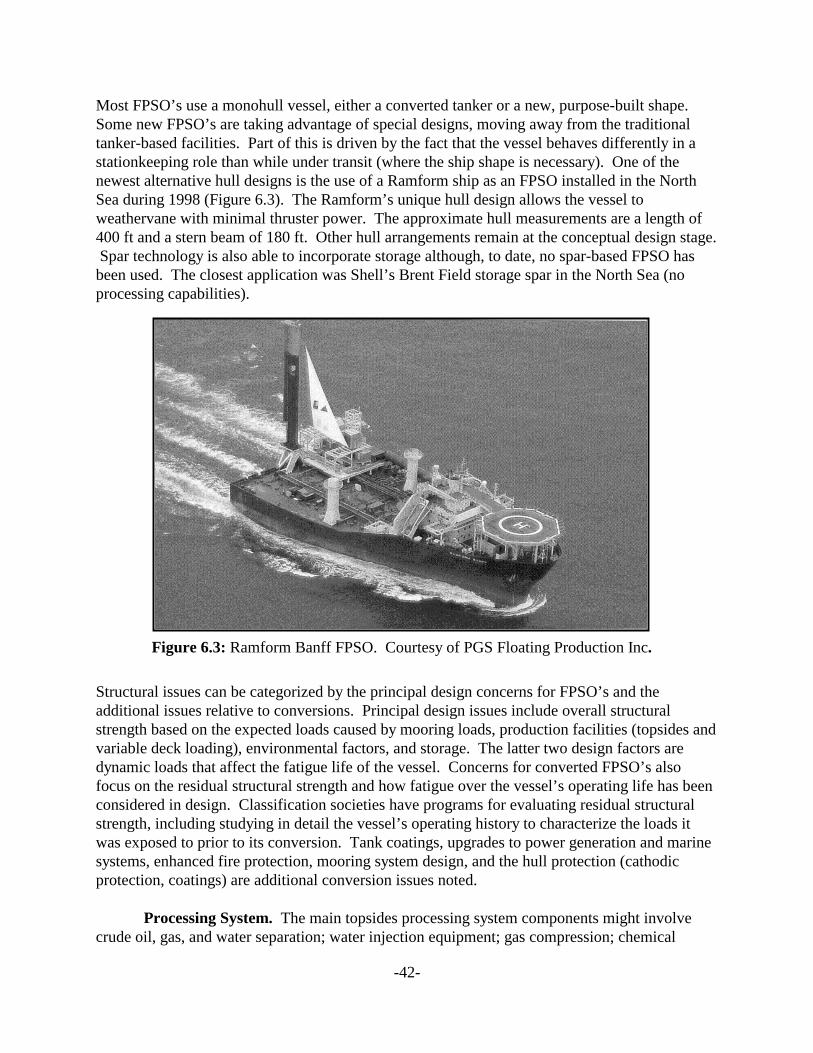
-42-
Most FPSO’s use a monohull vessel, either a converted tanker or a new, purpose-built shape. Some new FPSO’s are taking advantage of special designs, moving away from the traditionaltanker-based facilities. Part of this is driven by the fact that the vessel behaves differently in astationkeeping role than while under transit (where the ship shape is necessary). One of thenewest alternative hull designs is the use of a Ramform ship as an FPSO installed in the NorthSea during 1998 (Figure 6.3). The Ramform’s unique hull design allows the vessel toweathervane with minimal thruster power. The approximate hull measurements are a length of400 ft and a stern beam of 180 ft. Other hull arrangements remain at the conceptual design stage. Spar technology is also able to incorporate storage although, to date, no spar-based FPSO hasbeen used. The closest application was Shell’s Brent Field storage spar in the North Sea (noprocessing capabilities).
Figure 6.3: Ramform Banff FPSO. Courtesy of PGS Floating Production Inc.
Structural issues can be categorized by the principal design concerns for FPSO’s and theadditional issues relative to conversions. Principal design issues include overall structuralstrength based on the expected loads caused by mooring loads, production facilities (topsides andvariable deck loading), environmental factors, and storage. The latter two design factors aredynamic loads that affect the fatigue life of the vessel. Concerns for converted FPSO’s alsofocus on the residual structural strength and how fatigue over the vessel’s operating life has beenconsidered in design. Classification societies have programs for evaluating residual structuralstrength, including studying in detail the vessel’s operating history to characterize the loads itwas exposed to prior to its conversion. Tank coatings, upgrades to power generation and marinesystems, enhanced fire protection, mooring system design, and the hull protection (cathodicprotection, coatings) are additional conversion issues noted.
Processing System. The main topsides processing system components might involvecrude oil, gas, and water separation; water injection equipment; gas compression; chemical
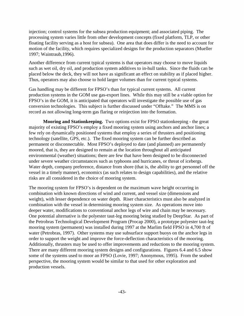
-43-
injection; control systems for the subsea production equipment; and associated piping. Theprocessing system varies little from other development concepts (fixed platform, TLP, or otherfloating facility serving as a host for subsea). One area that does differ is the need to account formotion of the facility, which requires specialized designs for the production separators (Mueller1997; Waintraub,1996).
Another difference from current typical systems is that operators may choose to move liquidssuch as wet oil, dry oil, and production system additives to in-hull tanks. Since the fluids can beplaced below the deck, they will not have as significant an effect on stability as if placed higher. Thus, operators may also choose to hold larger volumes than for current typical systems.
Gas handling may be different for FPSO’s than for typical current systems. All currentproduction systems in the GOM use gas-export lines. While this may still be a viable option forFPSO’s in the GOM, it is anticipated that operators will investigate the possible use of gasconversion technologies. This subject is further discussed under “Offtake.” The MMS is onrecord as not allowing long-term gas flaring or reinjection into the formation.
Mooring and Stationkeeping. Two options exist for FPSO stationkeeping - the greatmajority of existing FPSO’s employ a fixed mooring system using anchors and anchor lines; afew rely on dynamically positioned systems that employ a series of thrusters and positioningtechnology (satellite, GPS, etc.). The fixed mooring system can be further described aspermanent or disconnectable. Most FPSO’s deployed to date (and planned) are permanentlymoored, that is, they are designed to remain at the location throughout all anticipatedenvironmental (weather) situations; there are few that have been designed to be disconnectedunder severe weather circumstances such as typhoons and hurricanes, or threat of icebergs. Water depth, company preference, distance from shore (that is, the ability to get personnel off thevessel in a timely manner), economics (as such relates to design capabilities), and the relativerisks are all considered in the choice of mooring system.
The mooring system for FPSO’s is dependent on the maximum wave height occurring incombination with known directions of wind and current, and vessel size (dimensions andweight), with lesser dependence on water depth. Riser characteristics must also be analyzed incombination with the vessel in determining mooring system size. As operations move intodeeper water, modifications to conventional anchor legs of wire and chain may be necessary. One potential alternative is the polyester taut-leg mooring being studied by DeepStar. As part ofthe Petrobras Technological Development Program (Procap 2000), a prototype polyester taut-legmooring system (permanent) was installed during 1997 at the Marlim field FPSO in 4,700 ft ofwater (Petrobras, 1997). Other systems may use subsurface support buoys on the anchor legs inorder to support the weight and improve the force-deflection characteristics of the mooring. Additionally, thrusters may be used to offer improvements and reductions to the mooring system.There are many different mooring system designs and configurations. Figures 6.4 and 6.5 showsome of the systems used to moor an FPSO (Lovie, 1997; Anonymous, 1995). From the seabedperspective, the mooring system would be similar to that used for other exploration andproduction vessels.
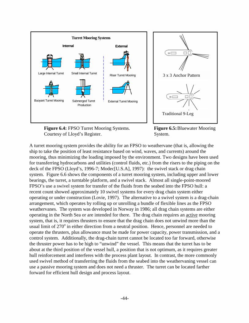
-44-
Figure 6.4: FPSO Turret Mooring Systems. Figure 6.5: Bluewater MooringCourtesy of Lloyd’s Register. System.
A turret mooring system provides the ability for an FPSO to weathervane (that is, allowing theship to take the position of least resistance based on wind, waves, and currents) around themooring, thus minimizing the loading imposed by the environment. Two designs have been usedfor transferring hydrocarbons and utilities (control fluids, etc.) from the risers to the piping on thedeck of the FPSO (Lloyd’s, 1996-7; Modec[U.S.A], 1997): the swivel stack or drag chainsystem. Figure 6.6 shows the components of a turret mooring system, including upper and lowerbearings, the turret, a turntable platform, and a swivel stack. Almost all single-point-mooredFPSO’s use a swivel system for transfer of the fluids from the seabed into the FPSO hull: arecent count showed approximately 10 swivel systems for every drag chain system eitheroperating or under construction (Lovie, 1997). The alternative to a swivel system is a drag-chainarrangement, which operates by rolling up or unrolling a bundle of flexible lines as the FPSOweathervanes. The system was developed in Norway in 1986; all drag chain systems are eitheroperating in the North Sea or are intended for there. The drag chain requires an active mooringsystem, that is, it requires thrusters to ensure that the drag chain does not unwind more than theusual limit of 270o in either direction from a neutral position. Hence, personnel are needed tooperate the thrusters, plus allowance must be made for power capacity, power transmission, and acontrol system. Additionally, the drag-chain turret cannot be located too far forward, otherwisethe thruster power has to be high to “unwind” the vessel. This means that the turret has to beabout at the third position of the vessel hull, a position that is not optimum, as it requires greaterhull reinforcement and interferes with the process plant layout. In contrast, the more commonlyused swivel method of transferring the fluids from the seabed into the weathervaning vessel canuse a passive mooring system and does not need a thruster. The turret can be located fartherforward for efficient hull design and process layout.
Turret Mooring Systems
Large Internal Turret Small Internal TurretRiser Turret Mooring
External Turret Mooring Submerged Turret Production
Buoyant Turret Mooring
InternalInternal ExternalExternal
Traditional 9-Leg
3 x 3 Anchor Pattern
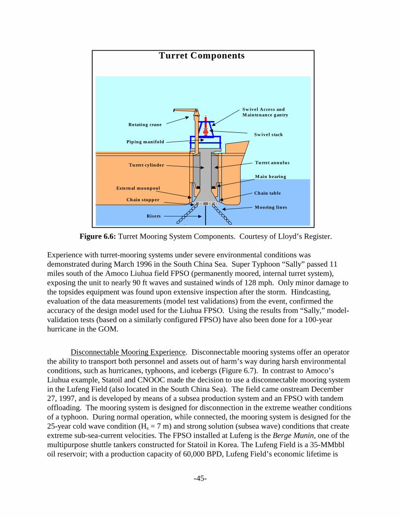
-45-
Figure 6.6: Turret Mooring System Components. Courtesy of Lloyd’s Register.
Experience with turret-mooring systems under severe environmental conditions wasdemonstrated during March 1996 in the South China Sea. Super Typhoon “Sally” passed 11miles south of the Amoco Liuhua field FPSO (permanently moored, internal turret system),exposing the unit to nearly 90 ft waves and sustained winds of 128 mph. Only minor damage tothe topsides equipment was found upon extensive inspection after the storm. Hindcasting,evaluation of the data measurements (model test validations) from the event, confirmed theaccuracy of the design model used for the Liuhua FPSO. Using the results from “Sally,” model-validation tests (based on a similarly configured FPSO) have also been done for a 100-yearhurricane in the GOM.
Disconnectable Mooring Experience. Disconnectable mooring systems offer an operatorthe ability to transport both personnel and assets out of harm’s way during harsh environmentalconditions, such as hurricanes, typhoons, and icebergs (Figure 6.7). In contrast to Amoco’sLiuhua example, Statoil and CNOOC made the decision to use a disconnectable mooring systemin the Lufeng Field (also located in the South China Sea). The field came onstream December27, 1997, and is developed by means of a subsea production system and an FPSO with tandemoffloading. The mooring system is designed for disconnection in the extreme weather conditionsof a typhoon. During normal operation, while connected, the mooring system is designed for the25-year cold wave condition (Hs = 7 m) and strong solution (subsea wave) conditions that createextreme sub-sea-current velocities. The FPSO installed at Lufeng is the Berge Munin, one of themultipurpose shuttle tankers constructed for Statoil in Korea. The Lufeng Field is a 35-MMbbloil reservoir; with a production capacity of 60,000 BPD, Lufeng Field’s economic lifetime is
Turret Components
Turret annulus
Mooring lines
Risers
Chain table
Main bearing
Swivel stack
Swivel Access andMaintenance gantry
Piping manifold
Chain stopper
External moonpool
Turret cylinder
Rotating crane
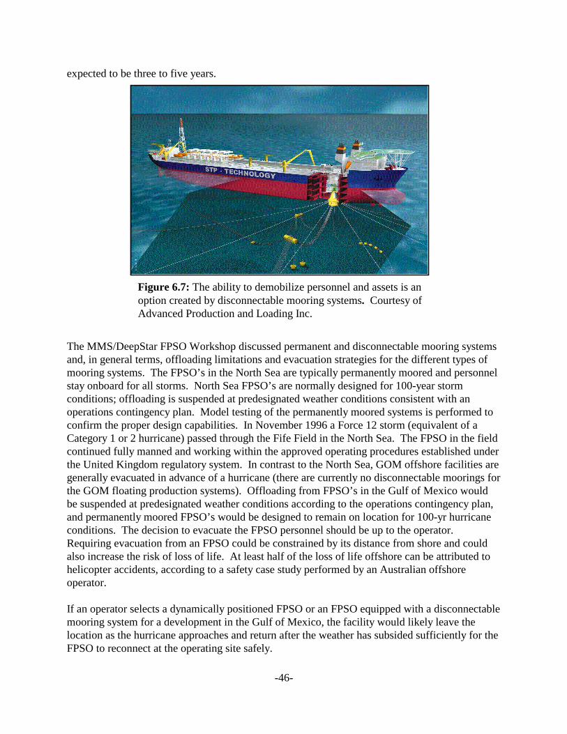
-46-
expected to be three to five years.
Figure 6.7: The ability to demobilize personnel and assets is an option created by disconnectable mooring systems. Courtesy of Advanced Production and Loading Inc.
The MMS/DeepStar FPSO Workshop discussed permanent and disconnectable mooring systemsand, in general terms, offloading limitations and evacuation strategies for the different types ofmooring systems. The FPSO’s in the North Sea are typically permanently moored and personnelstay onboard for all storms. North Sea FPSO’s are normally designed for 100-year stormconditions; offloading is suspended at predesignated weather conditions consistent with anoperations contingency plan. Model testing of the permanently moored systems is performed toconfirm the proper design capabilities. In November 1996 a Force 12 storm (equivalent of aCategory 1 or 2 hurricane) passed through the Fife Field in the North Sea. The FPSO in the fieldcontinued fully manned and working within the approved operating procedures established underthe United Kingdom regulatory system. In contrast to the North Sea, GOM offshore facilities aregenerally evacuated in advance of a hurricane (there are currently no disconnectable moorings forthe GOM floating production systems). Offloading from FPSO’s in the Gulf of Mexico wouldbe suspended at predesignated weather conditions according to the operations contingency plan,and permanently moored FPSO’s would be designed to remain on location for 100-yr hurricaneconditions. The decision to evacuate the FPSO personnel should be up to the operator. Requiring evacuation from an FPSO could be constrained by its distance from shore and couldalso increase the risk of loss of life. At least half of the loss of life offshore can be attributed tohelicopter accidents, according to a safety case study performed by an Australian offshoreoperator.
If an operator selects a dynamically positioned FPSO or an FPSO equipped with a disconnectablemooring system for a development in the Gulf of Mexico, the facility would likely leave thelocation as the hurricane approaches and return after the weather has subsided sufficiently for theFPSO to reconnect at the operating site safely.
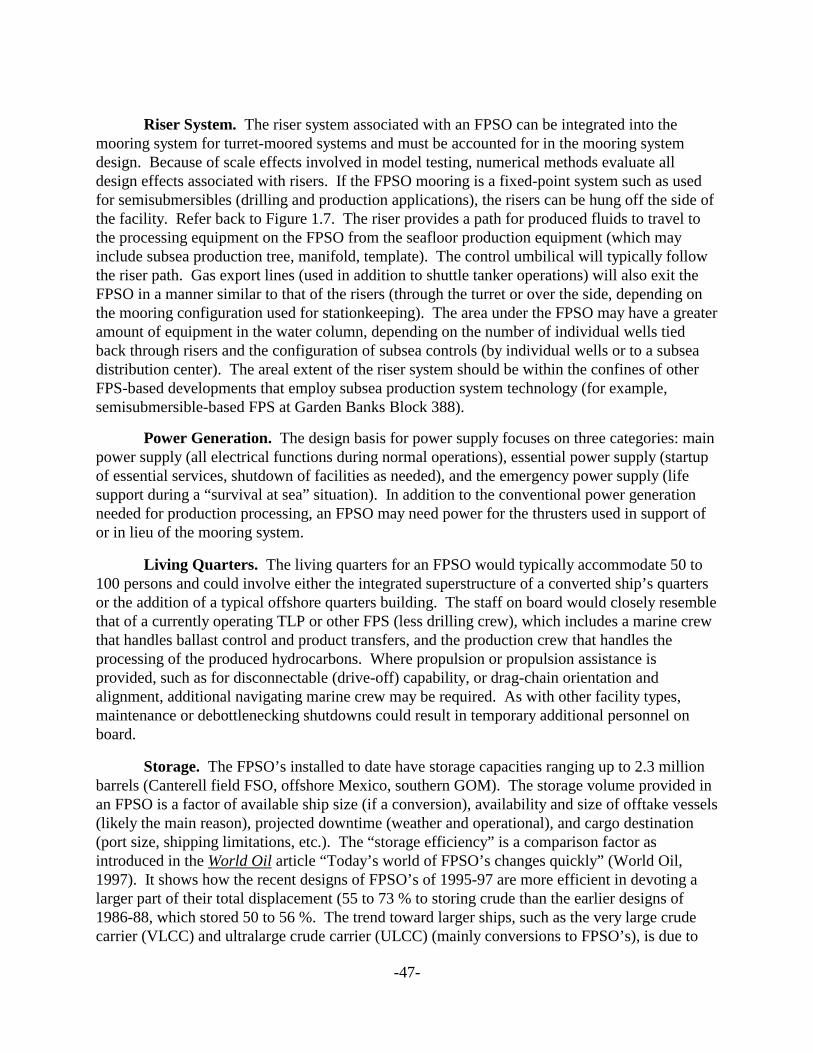
-47-
Riser System. The riser system associated with an FPSO can be integrated into themooring system for turret-moored systems and must be accounted for in the mooring systemdesign. Because of scale effects involved in model testing, numerical methods evaluate alldesign effects associated with risers. If the FPSO mooring is a fixed-point system such as usedfor semisubmersibles (drilling and production applications), the risers can be hung off the side ofthe facility. Refer back to Figure 1.7. The riser provides a path for produced fluids to travel tothe processing equipment on the FPSO from the seafloor production equipment (which mayinclude subsea production tree, manifold, template). The control umbilical will typically followthe riser path. Gas export lines (used in addition to shuttle tanker operations) will also exit theFPSO in a manner similar to that of the risers (through the turret or over the side, depending onthe mooring configuration used for stationkeeping). The area under the FPSO may have a greateramount of equipment in the water column, depending on the number of individual wells tiedback through risers and the configuration of subsea controls (by individual wells or to a subseadistribution center). The areal extent of the riser system should be within the confines of otherFPS-based developments that employ subsea production system technology (for example,semisubmersible-based FPS at Garden Banks Block 388).
Power Generation. The design basis for power supply focuses on three categories: mainpower supply (all electrical functions during normal operations), essential power supply (startupof essential services, shutdown of facilities as needed), and the emergency power supply (lifesupport during a “survival at sea” situation). In addition to the conventional power generationneeded for production processing, an FPSO may need power for the thrusters used in support ofor in lieu of the mooring system.
Living Quarters. The living quarters for an FPSO would typically accommodate 50 to100 persons and could involve either the integrated superstructure of a converted ship’s quartersor the addition of a typical offshore quarters building. The staff on board would closely resemblethat of a currently operating TLP or other FPS (less drilling crew), which includes a marine crewthat handles ballast control and product transfers, and the production crew that handles theprocessing of the produced hydrocarbons. Where propulsion or propulsion assistance isprovided, such as for disconnectable (drive-off) capability, or drag-chain orientation andalignment, additional navigating marine crew may be required. As with other facility types,maintenance or debottlenecking shutdowns could result in temporary additional personnel onboard.
Storage. The FPSO’s installed to date have storage capacities ranging up to 2.3 millionbarrels (Canterell field FSO, offshore Mexico, southern GOM). The storage volume provided inan FPSO is a factor of available ship size (if a conversion), availability and size of offtake vessels(likely the main reason), projected downtime (weather and operational), and cargo destination(port size, shipping limitations, etc.). The “storage efficiency” is a comparison factor asintroduced in the World Oil article “Today’s world of FPSO’s changes quickly” (World Oil,1997). It shows how the recent designs of FPSO’s of 1995-97 are more efficient in devoting alarger part of their total displacement (55 to 73 % to storing crude than the earlier designs of1986-88, which stored 50 to 56 %. The trend toward larger ships, such as the very large crudecarrier (VLCC) and ultralarge crude carrier (ULCC) (mainly conversions to FPSO’s), is due to
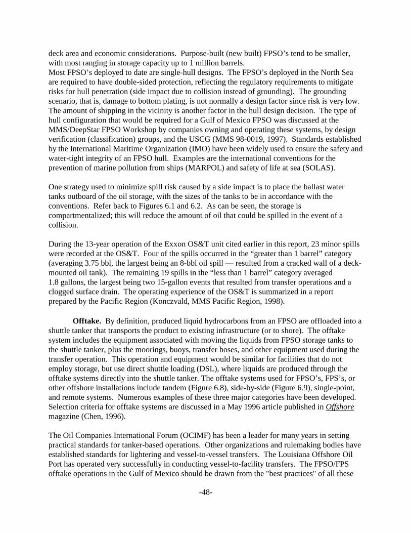
-48-
deck area and economic considerations. Purpose-built (new built) FPSO’s tend to be smaller,with most ranging in storage capacity up to 1 million barrels.Most FPSO’s deployed to date are single-hull designs. The FPSO’s deployed in the North Seaare required to have double-sided protection, reflecting the regulatory requirements to mitigaterisks for hull penetration (side impact due to collision instead of grounding). The groundingscenario, that is, damage to bottom plating, is not normally a design factor since risk is very low.The amount of shipping in the vicinity is another factor in the hull design decision. The type ofhull configuration that would be required for a Gulf of Mexico FPSO was discussed at theMMS/DeepStar FPSO Workshop by companies owning and operating these systems, by designverification (classification) groups, and the USCG (MMS 98-0019, 1997). Standards establishedby the International Maritime Organization (IMO) have been widely used to ensure the safety andwater-tight integrity of an FPSO hull. Examples are the international conventions for theprevention of marine pollution from ships (MARPOL) and safety of life at sea (SOLAS).
One strategy used to minimize spill risk caused by a side impact is to place the ballast watertanks outboard of the oil storage, with the sizes of the tanks to be in accordance with theconventions. Refer back to Figures 6.1 and 6.2. As can be seen, the storage iscompartmentalized; this will reduce the amount of oil that could be spilled in the event of acollision.
During the 13-year operation of the Exxon OS&T unit cited earlier in this report, 23 minor spillswere recorded at the OS&T. Four of the spills occurred in the “greater than 1 barrel” category(averaging 3.75 bbl, the largest being an 8-bbl oil spill — resulted from a cracked wall of a deck-mounted oil tank). The remaining 19 spills in the “less than 1 barrel” category averaged1.8 gallons, the largest being two 15-gallon events that resulted from transfer operations and aclogged surface drain. The operating experience of the OS&T is summarized in a reportprepared by the Pacific Region (Konczvald, MMS Pacific Region, 1998).
Offtake. By definition, produced liquid hydrocarbons from an FPSO are offloaded into ashuttle tanker that transports the product to existing infrastructure (or to shore). The offtakesystem includes the equipment associated with moving the liquids from FPSO storage tanks tothe shuttle tanker, plus the moorings, buoys, transfer hoses, and other equipment used during thetransfer operation. This operation and equipment would be similar for facilities that do notemploy storage, but use direct shuttle loading (DSL), where liquids are produced through theofftake systems directly into the shuttle tanker. The offtake systems used for FPSO’s, FPS’s, orother offshore installations include tandem (Figure 6.8), side-by-side (Figure 6.9), single-point,and remote systems. Numerous examples of these three major categories have been developed.Selection criteria for offtake systems are discussed in a May 1996 article published in Offshoremagazine (Chen, 1996).
The Oil Companies International Forum (OCIMF) has been a leader for many years in settingpractical standards for tanker-based operations. Other organizations and rulemaking bodies haveestablished standards for lightering and vessel-to-vessel transfers. The Louisiana Offshore OilPort has operated very successfully in conducting vessel-to-facility transfers. The FPSO/FPSofftake operations in the Gulf of Mexico should be drawn from the "best practices" of all these

-49-
resources. North Sea practice for offtake from facilities is described in Appendix B, “ShuttleTankers and FPSO’s.”
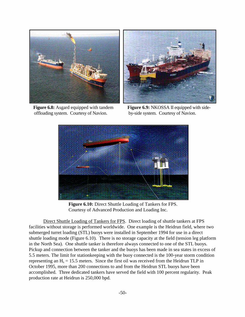
-50-
Figure 6.8: Asgard equipped with tandem Figure 6.9: NKOSSA II equipped with side- offloading system. Courtesy of Navion. by-side system. Courtesy of Navion.
Figure 6.10: Direct Shuttle Loading of Tankers for FPS. Courtesy of Advanced Production and Loading Inc.
Direct Shuttle Loading of Tankers for FPS. Direct loading of shuttle tankers at FPSfacilities without storage is performed worldwide. One example is the Heidrun field, where twosubmerged turret loading (STL) buoys were installed in September 1994 for use in a directshuttle loading mode (Figure 6.10). There is no storage capacity at the field (tension leg platformin the North Sea). One shuttle tanker is therefore always connected to one of the STL buoys. Pickup and connection between the tanker and the buoys has been made in sea states in excess of5.5 meters. The limit for stationkeeping with the buoy connected is the 100-year storm conditionrepresenting an Hs = 15.5 meters. Since the first oil was received from the Heidrun TLP inOctober 1995, more than 200 connections to and from the Heidrun STL buoys have beenaccomplished. Three dedicated tankers have served the field with 100 percent regularity. Peakproduction rate at Heidrun is 250,000 bpd.
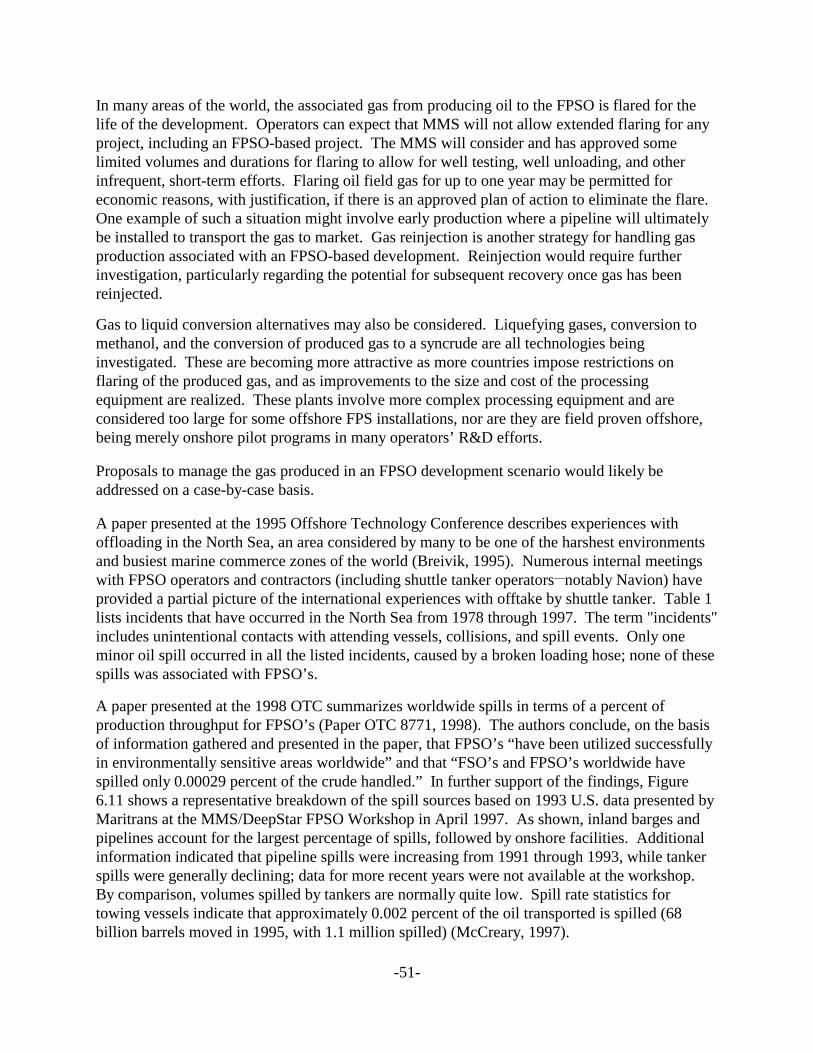
-51-
In many areas of the world, the associated gas from producing oil to the FPSO is flared for thelife of the development. Operators can expect that MMS will not allow extended flaring for anyproject, including an FPSO-based project. The MMS will consider and has approved somelimited volumes and durations for flaring to allow for well testing, well unloading, and otherinfrequent, short-term efforts. Flaring oil field gas for up to one year may be permitted foreconomic reasons, with justification, if there is an approved plan of action to eliminate the flare. One example of such a situation might involve early production where a pipeline will ultimatelybe installed to transport the gas to market. Gas reinjection is another strategy for handling gasproduction associated with an FPSO-based development. Reinjection would require furtherinvestigation, particularly regarding the potential for subsequent recovery once gas has beenreinjected.
Gas to liquid conversion alternatives may also be considered. Liquefying gases, conversion tomethanol, and the conversion of produced gas to a syncrude are all technologies beinginvestigated. These are becoming more attractive as more countries impose restrictions onflaring of the produced gas, and as improvements to the size and cost of the processingequipment are realized. These plants involve more complex processing equipment and areconsidered too large for some offshore FPS installations, nor are they are field proven offshore,being merely onshore pilot programs in many operators’ R&D efforts.
Proposals to manage the gas produced in an FPSO development scenario would likely beaddressed on a case-by-case basis.
A paper presented at the 1995 Offshore Technology Conference describes experiences withoffloading in the North Sea, an area considered by many to be one of the harshest environmentsand busiest marine commerce zones of the world (Breivik, 1995). Numerous internal meetingswith FPSO operators and contractors (including shuttle tanker operators__notably Navion) haveprovided a partial picture of the international experiences with offtake by shuttle tanker. Table 1lists incidents that have occurred in the North Sea from 1978 through 1997. The term "incidents"includes unintentional contacts with attending vessels, collisions, and spill events. Only oneminor oil spill occurred in all the listed incidents, caused by a broken loading hose; none of thesespills was associated with FPSO’s.
A paper presented at the 1998 OTC summarizes worldwide spills in terms of a percent ofproduction throughput for FPSO’s (Paper OTC 8771, 1998). The authors conclude, on the basisof information gathered and presented in the paper, that FPSO’s “have been utilized successfullyin environmentally sensitive areas worldwide” and that “FSO’s and FPSO’s worldwide havespilled only 0.00029 percent of the crude handled.” In further support of the findings, Figure6.11 shows a representative breakdown of the spill sources based on 1993 U.S. data presented byMaritrans at the MMS/DeepStar FPSO Workshop in April 1997. As shown, inland barges andpipelines account for the largest percentage of spills, followed by onshore facilities. Additionalinformation indicated that pipeline spills were increasing from 1991 through 1993, while tankerspills were generally declining; data for more recent years were not available at the workshop. By comparison, volumes spilled by tankers are normally quite low. Spill rate statistics fortowing vessels indicate that approximately 0.002 percent of the oil transported is spilled (68billion barrels moved in 1995, with 1.1 million spilled) (McCreary, 1997).
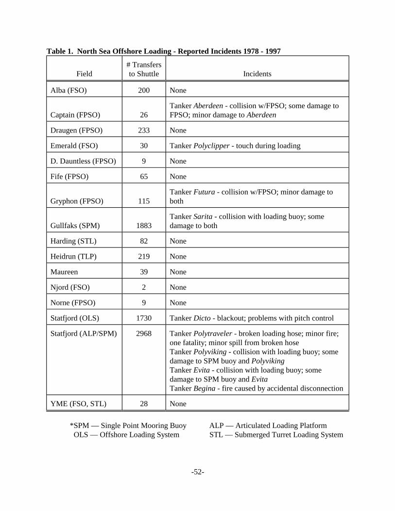
-52-
Table 1. North Sea Offshore Loading - Reported Incidents 1978 - 1997
Field# Transfersto Shuttle Incidents
Alba (FSO) 200 None
Captain (FPSO) 26Tanker Aberdeen - collision w/FPSO; some damage toFPSO; minor damage to Aberdeen
Draugen (FPSO) 233 None
Emerald (FSO) 30 Tanker Polyclipper - touch during loading
D. Dauntless (FPSO) 9 None
Fife (FPSO) 65 None
Gryphon (FPSO) 115Tanker Futura - collision w/FPSO; minor damage toboth
Gullfaks (SPM) 1883Tanker Sarita - collision with loading buoy; somedamage to both
Harding (STL) 82 None
Heidrun (TLP) 219 None
Maureen 39 None
Njord (FSO) 2 None
Norne (FPSO) 9 None
Statfjord (OLS) 1730 Tanker Dicto - blackout; problems with pitch control
Statfjord (ALP/SPM) 2968 Tanker Polytraveler - broken loading hose; minor fire;one fatality; minor spill from broken hoseTanker Polyviking - collision with loading buoy; somedamage to SPM buoy and PolyvikingTanker Evita - collision with loading buoy; somedamage to SPM buoy and EvitaTanker Begina - fire caused by accidental disconnection
YME (FSO, STL) 28 None
*SPM — Single Point Mooring Buoy ALP — Articulated Loading Platform OLS — Offshore Loading System STL — Submerged Turret Loading System
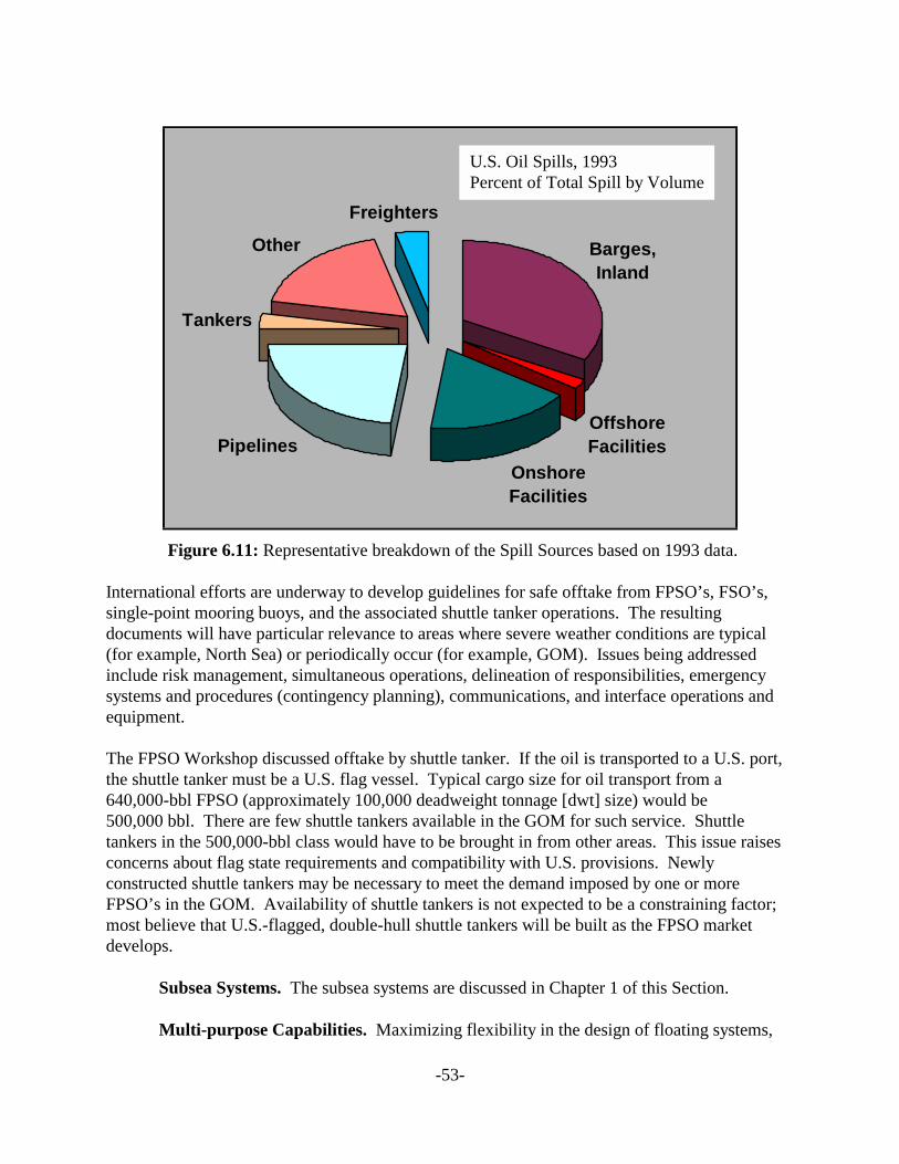
-53-
Barges, Inland
Offshore Facilities
Onshore Facilities
Pipelines
Tankers
Other
Freighters
Figure 6.11: Representative breakdown of the Spill Sources based on 1993 data.
International efforts are underway to develop guidelines for safe offtake from FPSO’s, FSO’s,single-point mooring buoys, and the associated shuttle tanker operations. The resultingdocuments will have particular relevance to areas where severe weather conditions are typical(for example, North Sea) or periodically occur (for example, GOM). Issues being addressedinclude risk management, simultaneous operations, delineation of responsibilities, emergencysystems and procedures (contingency planning), communications, and interface operations andequipment.
The FPSO Workshop discussed offtake by shuttle tanker. If the oil is transported to a U.S. port,the shuttle tanker must be a U.S. flag vessel. Typical cargo size for oil transport from a640,000-bbl FPSO (approximately 100,000 deadweight tonnage [dwt] size) would be500,000 bbl. There are few shuttle tankers available in the GOM for such service. Shuttletankers in the 500,000-bbl class would have to be brought in from other areas. This issue raisesconcerns about flag state requirements and compatibility with U.S. provisions. Newlyconstructed shuttle tankers may be necessary to meet the demand imposed by one or moreFPSO’s in the GOM. Availability of shuttle tankers is not expected to be a constraining factor;most believe that U.S.-flagged, double-hull shuttle tankers will be built as the FPSO marketdevelops.
Subsea Systems. The subsea systems are discussed in Chapter 1 of this Section.
Multi-purpose Capabilities. Maximizing flexibility in the design of floating systems,
U.S. Oil Spills, 1993Percent of Total Spill by Volume

-54-
Statoil has developed a new-built multipurpose shuttle tanker (MST) designed to accommodate awide range of topside production facilities. The MST is easily upgradable or modifiable for theneeded service between field development projects. The requirements of a shuttle tanker areintegrated with a monohull floating production facility to accommodate a range of loading andproduction options. The MST can also serve as a deepwater drillship. A practical example ofthe multiple roles that an MST can have is the new-built vessel West Navion under construction:the 830-ft-long unit will enter drilling service during 2000 as an ultradeepwater drillship (capableof drilling in water up to 10,000 ft deep). Oil storage capability in the MST will beapproximately 500,000 bbl (Statoil, 1997). However, published papers indicate a true combinedfunction drilling and production vessel, that is, a floating production, drilling, storage andoffloading vessel (FPDSO), would require a significantly larger vessel to accommodate bothfunctions simultaneously, for example, about a 270,000-dwt tanker. Simultaneous drilling froman FPSO is an industry goal, but is outside the scope of this paper.
Several dedicated ultradeepwater drillships (water depths greater than 7,500 ft) will enter GOMservice during 1999-2001, all with crude storage capabilities ranging up to 150,000 bbl. Whilethis would represent a small FPSO, the storage capability could be used for extended well testingpurposes, or could serve as the basis for a future conversion to an FPSO or FPU (the limitedstorage capacity providing the ability to remain on production at a reduced rate during short-termupset conditions, for example, shut-in of the export pipeline).
PROCESS DESCRIPTIONS
Construction. All construction work on the FPSO is completed at a shipyard prior totow-out to the offshore site. Most FPSO’s have been built (or converted) in shipyards in theNorth Sea and the Far East; at least two conversions have taken place in Gulf Coast shipyards. Recently, at least one GOM shipyard has indicated plans for expansion to accommodate theFPSO market. Topsides (production facilities, quarters, etc.) are modular and can be built at aseparate facility, then mobilized to the fabrication yard for final system integration and testing.
Deployment. Deployment of an FPSO is dependent on the type of mooring to be usedand can involve separate offloading systems. Since the use of FPSO’s involves subseaproduction technology, the subsea production and mooring (anchoring) equipment would beinstalled prior to mobilizing the FPSO to the location; this could also involve the installation ofthe seafloor and midwater part of the riser system. The Subsea Systems Chapter 1 of Section I ofthis paper describes techniques and equipment used in the installation work. Deploymentactivities (including tow-out) could involve three to four support vessels if the FPSO’spropulsion system has been removed or disabled. Deployment needs are a key consideration inthe turret design.
Maintenance and Inspection. The classification society rules address the types andfrequency of maintenance required. The range of possibilities are onsite maintenance andinspections (ROV, diver) or removal to shore for drydock inspection (requiring a temporaryabandonment of the facilities). The likely scenario would be to design the FPSO for the
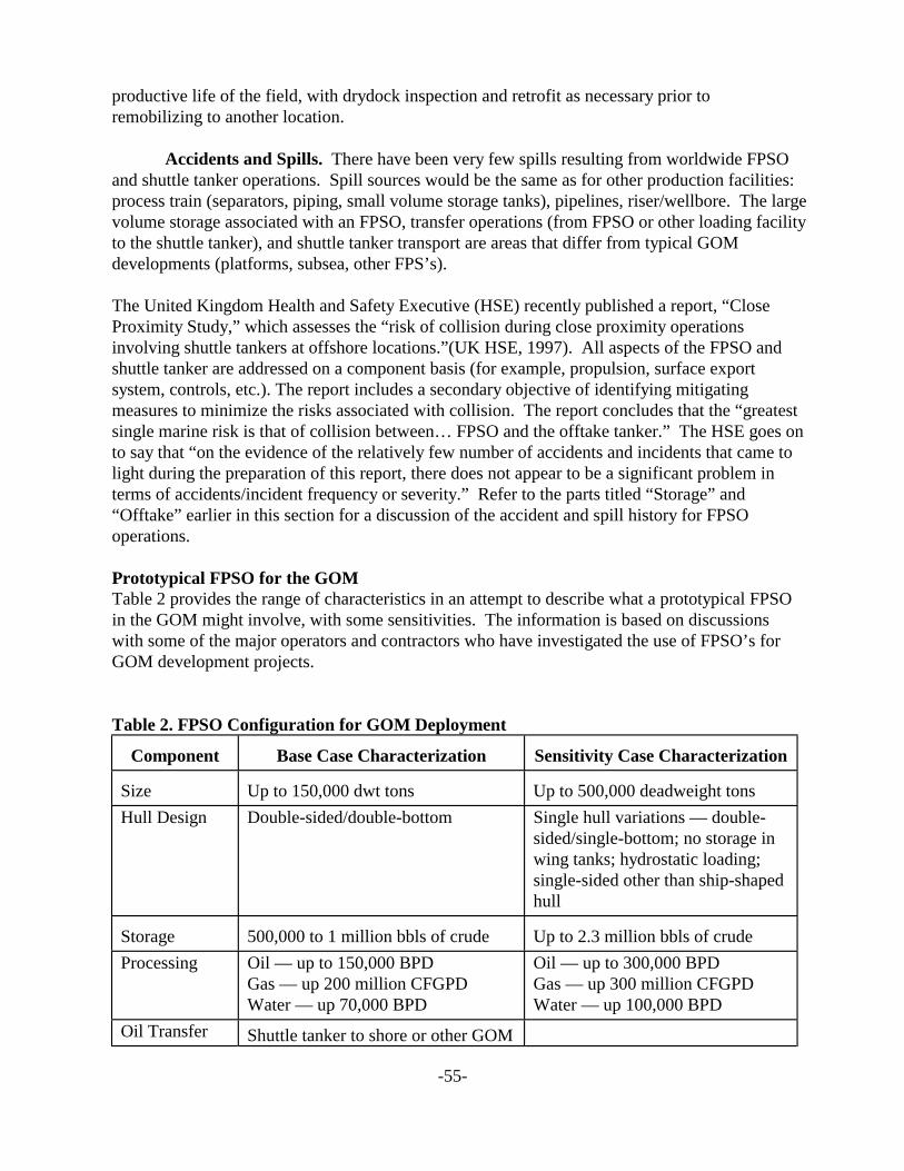
-55-
productive life of the field, with drydock inspection and retrofit as necessary prior toremobilizing to another location.
Accidents and Spills. There have been very few spills resulting from worldwide FPSOand shuttle tanker operations. Spill sources would be the same as for other production facilities:process train (separators, piping, small volume storage tanks), pipelines, riser/wellbore. The largevolume storage associated with an FPSO, transfer operations (from FPSO or other loading facilityto the shuttle tanker), and shuttle tanker transport are areas that differ from typical GOMdevelopments (platforms, subsea, other FPS’s).
The United Kingdom Health and Safety Executive (HSE) recently published a report, “CloseProximity Study,” which assesses the “risk of collision during close proximity operationsinvolving shuttle tankers at offshore locations.”(UK HSE, 1997). All aspects of the FPSO andshuttle tanker are addressed on a component basis (for example, propulsion, surface exportsystem, controls, etc.). The report includes a secondary objective of identifying mitigatingmeasures to minimize the risks associated with collision. The report concludes that the “greatestsingle marine risk is that of collision between… FPSO and the offtake tanker.” The HSE goes onto say that “on the evidence of the relatively few number of accidents and incidents that came tolight during the preparation of this report, there does not appear to be a significant problem interms of accidents/incident frequency or severity.” Refer to the parts titled “Storage” and“Offtake” earlier in this section for a discussion of the accident and spill history for FPSOoperations.
Prototypical FPSO for the GOMTable 2 provides the range of characteristics in an attempt to describe what a prototypical FPSOin the GOM might involve, with some sensitivities. The information is based on discussionswith some of the major operators and contractors who have investigated the use of FPSO’s forGOM development projects.
Table 2. FPSO Configuration for GOM Deployment
Component Base Case Characterization Sensitivity Case Characterization
Size Up to 150,000 dwt tons Up to 500,000 deadweight tons
Hull Design Double-sided/double-bottom Single hull variations — double-sided/single-bottom; no storage inwing tanks; hydrostatic loading;single-sided other than ship-shapedhull
Storage 500,000 to 1 million bbls of crude Up to 2.3 million bbls of crude
Processing Oil — up to 150,000 BPDGas — up 200 million CFGPDWater — up 70,000 BPD
Oil — up to 300,000 BPDGas — up 300 million CFGPDWater — up 100,000 BPD
Oil Transfer Shuttle tanker to shore or other GOM
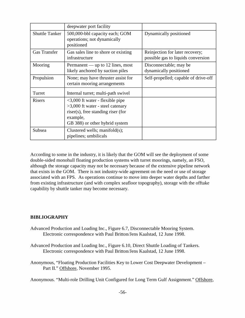
-56-
deepwater port facility
Shuttle Tanker 500,000-bbl capacity each; GOM operations; not dynamicallypositioned
Dynamically positioned
Gas Transfer Gas sales line to shore or existinginfrastructure
Reinjection for later recovery;possible gas to liquids conversion
Mooring Permanent — up to 12 lines, mostlikely anchored by suction piles
Disconnectable; may bedynamically positioned
Propulsion None; may have thruster assist forcertain mooring arrangements
Self-propelled; capable of drive-off
Turret Internal turret; multi-path swivel
Risers <3,000 ft water - flexible pipe>3,000 ft water - steel catenaryriser(s), free standing riser (forexample,GB 388) or other hybrid system
Subsea Clustered wells; manifold(s);pipelines; umbilicals
According to some in the industry, it is likely that the GOM will see the deployment of somedouble-sided monohull floating production systems with turret moorings, namely, an FSO,although the storage capacity may not be necessary because of the extensive pipeline networkthat exists in the GOM. There is not industry-wide agreement on the need or use of storageassociated with an FPS. As operations continue to move into deeper water depths and fartherfrom existing infrastructure (and with complex seafloor topography), storage with the offtakecapability by shuttle tanker may become necessary.
BIBLIOGRAPHY
Advanced Production and Loading Inc., Figure 6.7, Disconnectable Mooring System.Electronic correspondence with Paul Britton/Jens Kaalstad, 12 June 1998.
Advanced Production and Loading Inc., Figure 6.10, Direct Shuttle Loading of Tankers. Electronic correspondence with Paul Britton/Jens Kaalstad, 12 June 1998.
Anonymous, “Floating Production Facilities Key to Lower Cost Deepwater Development –Part II.” Offshore, November 1995.
Anonymous. “Multi-role Drilling Unit Configured for Long Term Gulf Assignment.” Offshore,
-57-
August 1997.
Anonymous, “Today’s World of FPSOs Changes Quickly – Part 1.” World Oil, April 1997.
BP Exploration, Government and Public Affairs Department, “Offshore Loading – Tried andTested.” Brochure.
Breivik, K.G., Statoil. “Experience with Offloading in the North Sea: Development of New CostEfficient Technology for Marine Storage and Production.” Copyright 1995. Paper OTC7723 presented at the 1998 Offshore Technology Conference, Houston, Texas, 1-4 May1995.
Chen, Bill C.M., “Selection of Offloading Configuration for FPSO Vessel.” Offshore, May 1996,pp. 64-8.
Intec Engineering, Inc., Figure 6.1, FPSO Field Development. Electronic correspondence withJoe Key, November 1998.
Konczvald, A., “Working Experience with the OS&T: 1981-1994.” MMS Pacific OCS RegionApril 1998.
Lloyd’s Register, Figure 6.2, Components of an FPSO. Electronic correspondence with AndrewJohnstone, 14 December 1999.
Lloyd’s Register, Figure 6.4, FPSO Turret Mooring Systems. Electronic correspondence withAndrew Johnstone, 14 December 1999.
Lloyd’s Register, Figure 6.6, Turret Components. Electronic correspondence with AndrewJohnstone, 14 December 1999.
Lloyd’s Register Technical Association. “FPSO Classification Accounting for the Variables.”Paper No. 1, Session 1996-7.
Lovie, Peter M., Bluewater Offshore Production Systems Ltd. “Today’s World of FPSOsChanges Quickly – Part 2.” World Oil, May 1997, pp. 95-104.
Minerals Management Service. OCS Report MMS 98-0019, “Floating Production, Storage, andOffloading Systems in the Gulf of Mexico__Proceedings of a Workshop.” Houston, 16 April1997.
Minerals Management Service. OCS Report MMS 98-0019, “Floating Production, Storage, andOffloading Systems in the Gulf of Mexico – Proceedings of a Workshop.” Houston, 16April 1997. Section titled “Marine Transportation and Safety Options.” p. 13.
Modec (U.S.A.), Inc. “Turret Arrangement.” FPSO Technology Overview. Briefing presented
-58-
to MMS, Herndon, Virginia, 19 August 1997.
Mueller, Wayne, “How FPSO Motion Affects Separator Performance, Controls.” Offshore,June 1997, pp. 84, 92.
Navion, Figure 6.8, Asgard Shuttle Tanker – Tandem Offloading Configuration. Electroniccorrespondence with Richard Amato, 20 December 1999.
Navion, Figure 6.9, NKOSSA II Shuttle Tanker – Side-by-Side Offloading Configuration. Electronic correspondence with Richard Amato, 20 December 1999.
Paper OTC 8771, “Reliability of Tanker Based FPSO’s for Deepwater Fields.” Copyright 1998.Paper presented at the 1998 Offshore Technology Conference, Houston, Texas, May 1998.
Petrobras. “Marlim Sul Field – Breaking Barriers in Offshore Oil Production.” PublicationAugust 1997.
PGS Floating Production Inc., Figure 6.3, Ramform Banff FPSO graphic. Electroniccorrespondence with William Pike, 7 April 1999.
Regg, James B., Representative Breakdown of the Spill Sources Based on 1993 Data. Presentationat the FPSO Workshop, 16 April 1997. Published proceedings as MMS-98-0019.
Statoil, “Innovation – Vision.” Brochure, Norne Field FPSO deployment.
Statoil, “Multipurpose Shuttle Tanker: The Flexible Solution for Cost-Efficient FieldDevelopment.” Brochure, 1997.
“Today’s World of FPSOs Changes Quickly – Part 2.” World Oil, May 1997. Figure 6.5, Self-generated graphic based on article.
UK HSE, Offshore Technology Report OTO 97 055, “Close Proximity Study.” October 1997.
Waintraub, L., “Separator Design Must Reflect Varying Motions of FPSO’s.” Offshore August1996, p. 90.
-57-
Section II: Deepwater Facility Operations
After the production system is installed, there are numerous operations that ensure safe- andpollution-free operations and support the continued flow of hydrocarbons. The following aretypical of post-installation operations:
• Commissioning and Startup! Startup could be “cold” or “hot”
• Normal Operations• Production Processing• Chemical Injection• Routine Testing• Maintenance and Repairs
! ROV, routine surface• Emergency Shutdown• Securing Facilities__Extreme Weather Events• Intervention
This paper describes in detail only those activities that differ in deepwater development projects.In many cases the technology and techniques applied to support production activities indeepwater are similar in scope to developments on the Outer Continental Shelf. Deepwater doesadd a level of complexity to the project, particularly subsea developments, since the facilitiesmay be located remote from the control (host) facility and are not readily accessible. Forexample, a workover may require a dedicated riser and control system, as well as a deepwater-capable rig (and all the support that comes with the drilling unit) or specialized interventionvessel. A significant amount of work is necessary for proper planning, simulation (transit andsteady-state), design, testing, and system integration before the deepwater development movesforward.
-58-
Chapter 1: DEEPWATER OPERATIONS
Commissioning and startup. Operations typically begin with systems integration testing (SIT)at a shore base or vendor or manufacturer’s facility. Particularly for subsea projects, the remotetools installation that will be used to make connections (for example, remotely operated vehicle[ROV]) will perform tests simulating the actual installation. Mobilization to and the startup ofinstallation at the offshore location can involve a large number of vessels, including drilling unit,support boats, derrick barge, transport barge and tugs, pipelay vessels, ROV’s, divers, etc. Section I of this paper describes the installation process for each of the various developmentsystems (TLP, spar, subsea, fixed platform, FPS). After installation, a series of final tests of theproduction equipment (on a system basis) are performed to ensure that the equipment isoperating as designed and in accordance with the MMS regulations. Production from the well atthis point will include completion fluids and reservoir fluids. These may be flared/burned,treated, and discharged overboard (in compliance with the provisions of EPA’s NationalPollutant Discharge Elimination System permits), or transported to shore for disposal at anapproved location. The cleanup phase of bringing a well/field on line may typically last two tofive days.
Production Processing. Production processing equipment is generally the same for bothshelf and deepwater developments. The production system may involve several separators, aseries of safety valves, treaters, compressors, pumps, and associated piping. For deepwaterfacilities, the production system may be designed to process higher rates of flow, ranging up to150,000 BOPD, 400 MMcfgpd, and 100,000 BWPD. These could include production frommultiple developments commingled at a common host facility.
The main surface production processing system components might involve crude oil separation,water injection equipment, gas compression, chemical injection, control systems for subseaproduction equipment, and associated piping. The processing system varies little from otherdevelopment concepts (fixed platform serving as a host for subsea, TLP__for example, Mars,etc.). One area that does differ is the need to account for vessel motion that may be induced byenvironmental forces on these floating production facilities. In these conditions, productionseparators require specialized designs.
Liquefied gases and conversion to methanol are technologies being investigated as alternativegas-handling procedures, eliminating flaring, and reinjection. These alternatives are becomingmore attractive as more countries impose restrictions on flaring of the produced gas, andimprovements to the size and cost of the processing equipment are realized. However, theseplants involve more complex processing equipment and are currently considered too large foroffshore installations.
Upsets/Shut insThe surface-piercing facilities, both fixed and floating systems, address process upsets in thesame manner as do conventional development projects. With subsea developments, the well mayremain open during a surface facility upset to allow the line to pressurize (minimizing closing the
-59-
valve against pressure, thus extending the life of the valve and ensuring the valve is operableunder emergency situations). A programmed delay is oftentimes incorporated into the safetysystem design with an operator override. This difference is the result of recognizing the differentfunctional aspects (criteria, operation, responsibilities) of the various safety devices. In all shut-ins, the boarding pipeline shutdown valve is closed.
Chemicals. Produced fluid problems in deepwater are a critical issue (colder seafloortemperatures, produced water, condensates, paraffin, and asphaltene contents in the oil), one thatcan compromise the viability of a development project. To remedy that concern, there is anincreased reliance on the use of chemicals for production assurance. The use of chemicals inoffshore oil production processes is not a new approach. Some of the chemicals used arecorrosion inhibitors; workover/packer fluids (weighted clear fluids__bromides, chlorides, etc.);hydrate and paraffin inhibitors; defoamers; solvents (soaps, acids); glycol; diesel; etc. Thesechemicals are typically used for batch treatments, small-volume continuous injections, andremedial treatments such as workover operations. Material Safety Data Sheets are required forall chemicals used offshore.
Corrosion inhibitors are used to protect carbon-steel components of the production system thatare wetted by the produced fluids. Material selection is a critical factor in the proper design of aproduction system, requiring information about the composition of the produced fluids(compositional analysis). The National Association of Corrosion Engineers (NACE) has severalmaterial selection standards to assist with proper design, including these:
• Corrosion is a 3-phase flow phenomenon (oil, gas, water).• The inhibitors are typically injected at the production tree, downhole, into
manifolds and pipelines, etc.• Example storage: 500-gallon deck-mounted tank.• Delivery would be on the order of 7,500 gallons per year (dependent on the
production;assuming a 50-ppm concentration in the produced water); higherconcentrations may be necessary (100 ppm).
• The volume of corrosion inhibitor injected may increase substantially if there is ahigh volume of produced water, a normal occurrence during the laterproducing years of many fields.
Paraffin inhibitors are used to protect the wellbore, production tree, and pipelines/flowlinesfrom plugging. The injection of these chemical inhibitors is dependent on the composition ofthe produced fluids. Injection can occur continuously at the tree, pipeline, manifold, and othercritical areas while the production stream is hot, and to batch treatments at production startupand shut-ins. The wax content, pour point, and other factors are determined prior to beginningproduction to determine chemical(s) needed, if any, and the best method for treatment. For a10,000-bopd well, the paraffin inhibitor could be injected at a rate of 30,000 gallons per year(enough to ensure a 200-ppm concentration in the produced fluid stream).
-60-
Hydrate inhibition is normally associated with startup and shut-ins (planned or unplanned), thatis, batch treatments. Continuous injection also occurs when there is induced cooling likely dueto chokes and natural cooling of pipelines from cold ambient temperatures at the seafloor. Methanol is one of the most common hydrate inhibitors used, particularly for subsea wells and inarctic regions where rapid cooling of the produced fluid stream (gas and water) can cause hydrateformation. Methanol is injected into the tree and sometimes downhole just above the subsurfacesafety valve while the fluids are hot. Some subsea developments in the deepwater GOM willinject methanol at rates of 20 to 40 percent of the water production rate.
Asphaltene inhibitors are injected in the same manner as the other inhibitors, but on a continuousbasis. Asphaltenes can form in the production system as the pressure declines to near the bubblepoint (where gas is first liberated from solution).
An alternative method of inhibition for paraffins and hydrates, and for remedial work in the eventof plugging, is to circulate “dry oil” through the system; storage volumes between 100 and 1,000bbls of “dry oil” would be integrated into the production system.
Most development projects require one or all of these chemical inhibitors to avoid produced fluidproblems. Several notable projects requiring hydrate inhibitors include Mensa, Morpeth, Arnold,and Troika. There are efforts underway to improve the performance of the inhibiting chemicalsand to reduce the toxicity of the chemicals.
Delivery. Numerous chemicals are delivered to the proper part of the production system throughone or more injection skids located on the platform (production facility, subsea host facility). The injection skid comprises pumps, regulators, accumulators, valving, piping, controls, andinstrumentation to ensure accurate delivery to the production system (volume, location,concentration). Remote subsea development systems (tied to a host-processing facility) have theadded complication of chemical delivery and distribution through a control umbilical. (Refer toSection I, Chapter 1, “Subsea Systems” for a description of an umbilical.)
Transport. Dry (bulk) chemical will likely be transferred to the offshore platform (productionplatform or host facility) from a supply vessel; if in sacks, the dry chemical would likely beplaced on a pallet and secured prior to transport. Dry chemical via bulk could be either airliftedfrom the supply vessel storage or transferred via portable bulk storage tanks. As an alternative,the dry chemical could be transported by helicopter (for example, sling load).
Liquid oil field chemicals will be transferred to the offshore production facility by DOT-approved transporter tanks (approximately 500 gal each), portable tote tanks, drums (individuallyor several on a pallet), or offloaded by pumping from the supply vessel’s storage tank to theplatform storage tank(s).
Storage. The size and location of chemical storage facilities vary depending on the amount andtype of treatment used. Continuous treatments typically involve small volume injections andmay be used for inhibiting corrosion and produced fluid problems under normal operations. Batch treatments will involve larger volume deliveries over a short time period (hours) to prevent
-61-
paraffin and hydrate formation during the cool-down that occurs when production flow is shut in.Three general storage systems have been used for methanol storage on the shelf and deepwaterfacilities in the GOM:
• portable tote tanks, stored in a predesignated chemical storage location with appropriate fire protection and safety equipment;
• deck-mounted storage tank(s) with similar safety provisions;• subsea methanol storage caisson.
Typical storage capacity for methanol would range from less than 100 to 3,000 barrels,depending on the number of wells requiring injection, the hydrate formation potential, waterproduction, and water depth. Other chemicals will be stored in the portable tanks, tote tanks,or drums with volumes normally less than 20 barrels each. The move into deeper water and theuse of multiple subsea well clusters (including multiple wells per cluster) will require the useof larger umbilicals for the distribution of chemicals for flow assurance. This may necessitatethe use of a subsea chemical distribution system where a single riser transports the chemical tothe seafloor. From there, chemicals would be pumped to the individual trees and pipeline asneeded. Such a system has been installed in the North Sea for the Foinaven FPSOdevelopment. Efforts are underway to improve subsea chemical distribution system design(miniaturize electronic modules, improve control pod design and reliability, standardizeequipment); much of the effort is directed at taking advantage of ROV technology to assistwith controls and repairs (freeing up the more expensive intervention vessels and drilling rigs). A significant challenge in design is properly considering the effect that the chemicals have onpumps and other distribution system equipment. Failure to do so can lead to costly repairs anddowntime that can be detrimental to a subsea project. The costs and risks associated with afailure (plugging the lines, downtime, intervention) must be balanced against the use ofexisting technology, that is, a large, long multitube umbilical.
Well Testing. As part of Phase I of the DeepStar effort, several reports were preparedto summarize routine well testing, extended well testing, and what is meant by each. Flowtesting is done to confirm the producibility of the reservoir and to locate any boundary effectsthat could limit long-term production. In some instances, an extended well test may benecessary to confirm the development potential. A well test could last for several days to amonth. For an extended test, the actual producing time (well flowing) is typically less thanone-half the total test time. Significant data are gathered about the system from the pressurebuild-up stage of a well test. Oil recovered as part of the well test will be stored and reinjected,burned, or transported to shore for sales or disposal; gas is normally flared during the test. TheMMS has limits for the duration of allowable flaring and burning operations.
Inspection and Maintenance. Facilities and pipelines require periodic inspections toensure there is no external damage or hazards that will affect the system integrity. Unlike theshallow-water shelf platform and subsea completions where diver access is possible, thedeepwater requires the use of ROV’s for surveys and some repairs. For floating systems suchas the TLP, the survey would examine the tendons as well as the hull and production riser. Periodic seafloor surveys may also be conducted to confirm wellbore integrity (that there is no
-62-
pressure communication from shallow pressured zones or the wellbore to the seafloor). Inspections of other systems would investigate the mooring system components as well as theproduction components (trees if subsea, pipelines, risers, umbilical, manifold, etc.).
Many of the components on subsea equipment are modular, with built-in redundancy toexpedite retrievals in the event of a failure. Mobilization of a drilling rig or specializedintervention vessel would be required for intervention into any of the subsea systems. If theproduction equipment is surface-based, the maintenance, retrieval, and repair would be similarin scope to the conventional fixed platforms.
Intervention. Intervention into a wellbore may be done for recompletion, workover,and well control purposes. Some of the new generation deepwater facilities do notincorporate the ability to install a drilling rig on the deck, so intervention must be completedwith a mobile drilling rig (semisubmersible or drillship) or a specialized intervention vessel. Using a drilling rig would be similar to mobilizing for a drilling operation, except the lengthof time at location would be much less (10 to 30 days, depending on the complexity of theintervention).
Intervention to regain control of a well is more complex for subsea wells; there are alsosignificant well control challenges for deepwater in general. An addendum to this section,“Deepwater Blowouts,” summarizes some of the risks, blowout scenarios, and practicalsolutions that the offshore industry and MMS are investigating. Industry efforts are underwayby the well control experts (consultants, contractors, oil companies, trade groups) to improvethe understanding of needs, processes, and existing capabilities. One notable effort is theIADC/OOC Deep Water Well Control Task Force, addressing well planning, well controlprocedures, equipment, emergency response, and training. The IADC/OOC described itsfindings and recommendations in a late 1998 report. The MMS participated in this effort atthe steering committee level.
Extreme Weather Operations. Securing wells and evacuating a facility in advanceof an extreme weather event is not unique to the deepwater. Operating experience from over3,000 platforms in the Gulf of Mexico over a period of many years has demonstrated thesafety of evacuation procedures for severe weather conditions. Criteria and models forshutdown of operations and an orderly evacuation for an approaching hurricane have been inplace in the GOM for over 30 years. As activities move farther from shore, however, it maybecome safer to not evacuate the facility, since helicopter operations may become inherentlymore risky due to the greater flight times and distances associated with remote offshoreoperations. Severe weather conditions will also increase the risks associated with helicopteroperations. The precedent for leaving a facility manned during severe weather is establishedin North Sea and other operating basins.
Part of the pre-installation efforts, testing, and the actual operating experience (under normalconditions and in response to emergency situations) is to formulate the exact time needed tosecure the wells and production facility, and abandon as necessary. A company will develop a
-63-
site-specific curtailment, securing, and evacuation plan that will vary in complexity andformality by operator and type of activity. In general terms, these are all intended to makesure the facility (or well) is secured in advance of a pending storm or developing emergency.The operating procedures developed during the engineering, design, and manufacturing phasesof the project, coupled with the results (recommended actions) from hazard analysesperformed, will be used to develop the emergency action or curtailment plans.
For a severe weather event such as a hurricane, emergency curtailment plans would addressthe criteria and structured procedures for suspending operations and ultimately securing thewellbore(s) prior to weather conditions that could exceed the design operating limitations ofthe drilling or production unit. For drilling operations, the plan might also address proceduresfor disconnecting and moving the drilling unit off location after the well has been secured,should the environmental conditions exceed the floating drilling unit's capability to maintainstation. Curtailment of operations consists of various stages of "alerts" indicating thedeterioration of meteorological, oceanographic, or wellbore conditions. Higher alert levelsrequire increased monitoring, the curtailment of lengthy wellbore operations and, if conditionswarrant, the eventual securing of the well. If conditions improve, operations could resume,based on the limitations established in the contingency plan for the known environmentalconditions.
Evacuation and production curtailment must consider a combination of factors, includingmeteorological monitoring, weather forecasting, well status (drilling, producing, etc.), and thetype and mechanics of wellbore operations. These factors are analyzed onsite through adecisionmaking process that involves onsite facility managers. The emphasis is on makingreal-time, situation-specific decisions and forecasting based on available information.
Ensuring adequate time to suspend operations and secure the well safely and efficiently is akey component of the planning effort. Time requirements are reviewed and analyzed asenvironmental conditions and the types of wellbore operations change. Extensive monitoringof the weather is conducted to ensure early warning of potential and impending hazardoussituations. Clearly defined responsibilities for the facility personnel are part of the successfulimplementation of the emergency response effort.
-64-
Chapter 2: DEEPWATER BLOWOUTS
The oil industry’s experience base in deepwater well control is limited. Current U.S. Gulf ofMexico exploratory drilling is taking place in excess of 7,000 ft of water. With deepwaterwell production rates achieving in excess of 20,000 BOPD and 100 MMscfd, the OCSprogram can ill afford a deepwater blowout with unsustained flow at these rates. A deepwaterblowout of this magnitude in the U.S. Gulf of Mexico could easily turn out to be a potentialshowstopper for the OCS program if the industry and MMS do not come together as a wholeto prevent such an incident.
Deepwater Well Control Difficulties• No single company has the solution.• Capping and controlling well flow at the seabed.• Fighting the fire at the surface.• Rig, riser, and associated deepwater drilling equipment availability are limited.• Research into a solution will be expensive.• Real test will come if a deepwater blowout occurs.
Risks• Spill potential from oil and condensate migrating from the seafloor through the water
column.• Fire potential from natural gas reaching its flashpoint when liberated at the water
interface.• Blowouts could be mitigated by low-formation strength and natural well bridging.• High productivity (rates) and flowing bottomhole pressures could limit natural well
bridging.• Stuck drillpipe will result if the well bridges.• Underground blowout risk will be substantial.• Surface blowouts should be unsustained unless flow up the drill pipe is restricted.• Broached blowouts will result if there is casing failure.• Gas hydrate plugging of choke lines.• Deeper water depths will add a significant hydrostatic backpressure at the mudline as
long as drill pipe remains unsheared.• Risks lower during completion and workover operations.
Deepwater Blowout Scenarios• Sheared drill pipe blowout followed by an underground blowout below the casing shoe
∙ Worst case scenario.∙ Drill pipe may drop or still be landed within the subsea blowout preventer.∙ Pressure builds up suddenly on the annulus and ruptures the casing or casing shoe.∙ Well blows out again, this time underground.∙ Possible mudline broaching with shallow casing failure.
-65-
• Drill pipe blowout∙ Common U. S. Gulf of Mexico OCS example.∙ Flow is through the drill bit and bottomhole assembly.∙ Drill pipe kicks if well bridges.∙ High shut-in and rapid pressure buildup in the drill pipe can lead to drill pipe failure.∙ Only option at this point is to close shear rams.∙ Intervention is complicated.
• An underground blowout that bridges, resulting in a drill pipe kick.∙ Hydrostatic drill pipe pressure balances with underground-flowing bottomhole pressure.∙ Mud level drops in drill pipe.∙ Well bridges, shutting off underground flow.∙ Drill pipe kicks.∙ Severe hydraulic hammer occurs at the surface when mud that remained in the drill pipe is rapidly pushed to the surface by the kick.∙ Upper and lower kelly cock valves and standpipe gate valves are unable to close or cut out.∙ Well blows out drill pipe at mud pump.
Potential Solutions• Plugging the blowout from the existing rig
∙ The use of a reactive gel mixture that would solidify quickly could mean that the rig itself would carry enough chemicals on the deck to kill the blowout. The traditional dynamic kill method, which will require pumping at a very high rate,
and injecting a massive volume of fluids with very powerful pumps cannot be used.∙ Advantage of having a tremendous hydrostatic column (several thousand ft of water) exerting pressure on the formation, choking down the flow of oil.∙ Dramatic advantage of oil and condensate traveling a great distance away from the rig before reaching the flash point, at which the explosive natural gas drops out of solution.∙ Should natural gas collect under the rig, a catastrophe is possible.
• Using an alternative rig to drill a relief well∙ Means more pollution, since time is needed to mobilize the alternative rig or suitable equipment (specifically BOP stack and marine drilling riser) to location and drill the relief well; time is dependent on the location of a suitable rig and the operation that must be terminated (for example, it may be necessary for a working rig to run casing before it can be released to drill a relief well, and mobilization time may require resupply); may be some logistical problems involved in mobilizing personnel and equipment on location to drill a relief well.∙ Scarcity of rigs, drilling risers, and associated deepwater drilling equipment to drill a relief well; may not be necessary unless the rig drilling the blowing well has been damaged.
-66-
∙ Formal agreement is needed by operators to use a compatible rig that will be able to shut down its operations and move on location to drill the relief well.∙ Blowout contingency and relief well intervention plans are needed to improve an operator’s response time to minimize loss and additional risks.
• Mechanical shutoff for a subsea blowout is possible under some conditions asdemonstrated in a recent event offshore Italy (≈ 2,000 ft water depth.)
BIBLIOGRAPHY
Flak, L., Boots & Coots. “Ultra-Deepwater Blowouts – How Could One Happen?”Offshore, January 1997, pp.61-2.
IADC/OOC Deepwater Well Control Task Force. Deepwater Well Control Guideline,1998.
Kruse, B.J., Minerals Management Service. “Deepwater Well Control: Where’s the Fire?”Offshore, September 1997.
Lyons, B., P. Strong, and L. Ebb, “Italian Wildcat First Deepwater Subsea Well Kill.”Offshore, November 1999.
Regg, J. “Regulation of Floating Drilling Unit Operations in the Beaufort and Chukchi SeaOuter Continental Shelf. IADC/SPE 23922 Minerals Management Service, 1992.
-67-
Section III: Transportation--Related Issues Associated With Deepwater Development
OVERVIEW
This section concerns transportation-related issues that may result in impacts to air quality,water quality, and the seafloor during deepwater oil and gas exploration, development, andproduction. The ability to transport product has always been an important factor in thesuccessful development of a gas or oil field, both onshore and offshore. For transportingoffshore production, the method chosen by most producers has historically been pipelines. The technology involved in transporting product from offshore gas and oil fields located in theshallower waters of the Gulf of Mexico Outer Continental Shelf (the shelf) has evolved to thelevel of the routine and commonplace. Much of the same technology will be employed in thedeeper waters beyond the edge of the continental slope (the slope), but there are notabledifferences between the operating environments of shallow water and deepwater thatchallenge the technology. Some significant differences between shallow water and deepwaterareas are the remoteness, that is, the distance from onshore support facilities; the water depthitself, which renders conventional vessel mooring systems unusable; the colder temperature ofthe deepwater: and the seafloor topography. The produced fluids from deepwater gas or oilwells flowing into a riser or pipeline that is at the same temperature as the cold watersurrounding it tend to form gas hydrates, solid crystalline substances composed ofhydrocarbon gas combined with water, and paraffin, a waxy solid associated with hydrocarbonliquids. Unless some action is taken to prevent or remediate the formation of hydrates and theaccumulation of paraffin, the amount of these substances within the riser or pipeline willincrease and the amount of fluid flow through the pipe will become restricted and couldeventually be reduced to zero.
Unlike the gradual sloping typical of the shelf seafloor, the seafloor beyond the slope isextremely irregular. This means that suitable routes for proposed pipelines are fewer andmore difficult to choose. An uneven seafloor could result in unacceptably long lengths ofunsupported pipeline, referred to by pipeline designers as “spanning,” which in turn could leadto pipe failure from bending stress early in the life of the line.
Numerous papers have been published that highlight changes that have faced deepwaterpipeline projects and ongoing development. This section relies heavily upon publishedmaterials from technical meetings and trade journals, production company deepwateroperations plans, and personal communications with independent contractors to describe thetechnical aspects of transportation activities. No recommendations are made for anyparticular plan or project; only current practices and procedures are presented. This methodallows open discussions to review systems, projects, and procedures, and to arrive at a betteroverall understanding of proposed concepts and installations.
-68-
Only 25 years ago the water depth at the edge of the continental shelf, 200 meters (656 ft) wasconsidered deepwater. Few rigs at the time had the capability to drill beyond that water depthand there was little certainty of finding oil on the continental slope. Then, about 15 years ago,a large number of discoveries made in the “flex trend” (600 to 1,600 ft water depth range)sparked interest in drilling at the edge of the Continental Shelf and on the slope. The largenumber of 100 million-barrel fields discovered beyond the 1,000-ft depth contour, continuedsuccesses in sustained production rates, and technology applications have extended the reachof offshore exploration, production, and pipelining into unprecedented water depths in theU.S. Gulf of Mexico.
The four issues to be covered in this section are
- Pipeline Installation Methods- Spanning- Methods for Maintaining Flow Assurance - Alternative Transportation Options
-69-
Chapter 1: PIPELINE INSTALLATION METHODS
S-lay Method by Conventionally Moored Lay Barges. In this section, the term“conventionally moored” means that the location or position of the installation vessel (laybarge) is maintained through anchors, associated anchor chains, and/or cables.
The traditional method for installing offshore pipelines in relatively shallow water iscommonly referred to as the S-Lay method because the profile of the pipe as it moves in ahorizontal plane from the welding and inspection stations on the lay barge across the stern ofthe lay barge and onto the ocean floor forms an elongated “S.”
As the pipeline moves across the stern of the lay barge and before it reaches the ocean floor,the pipe is supported by a truss-like circular structure equipped with rollers and known as astinger. The purpose of the stinger in the S-lay configuration is to control the deflection of thepipe in the over-bend region above the pipeline inflection point in order to return the angle ofthe pipeline at the surface to the horizontal. The curvature radius of the stinger corresponds toat least the maximum bending stress. To avoid a bending moment peak at the last roller, thepipe must lift off smoothly from the stinger well ahead of the lower end of the stinger.
In extremely deep water the angle of the pipe becomes so steep that the required stinger lengthmay not be feasible. Deeper water depths will result in a steeper lift-off angle of thesuspended pipe span at the stinger tip. This will require the stinger to be longer and/or morecurved to accommodate the greater arc of reverse curvature in the overbend region. Accordingly, greater stinger buoyancy and/or structural strength will be necessary to supportthe increased weight of the suspended pipe span.
Water Depth Limits. The practical water depth limit for a large, conventionally moored laybarge that uses the S-lay method is about 1,000 ft, based on a ratio of anchor line length towater depth of about five to one. Therefore, construction of pipelines by conventionallymoored lay barges, if used in conjunction with the development of deepwater oil or gasdiscoveries in the Gulf of Mexico, will probably be limited to those portions of the pipelineroutes located in water depths less than 1,000 ft.
Anchoring. Smaller lay barges, in the 400 ft long by 100 ft wide size range, typically requireeight anchors each weighing 30,000 lbs, and a larger barge operating in 1,000 ft of watertypically requires 12 anchors (3 anchors per quarter), each weighing 50,000 lbs or more.
In general, the larger the vessel, that is, the greater the target area presented to wind, wave,and current forces, and the heavier the vessel, the higher the holding requirements will be forthe mooring system. The rated holding capacity of an anchor system is a function of theweight and size of the anchor and the tensile strength of the chain or cable that secures theanchor to the vessel. An important factor to be considered when there is a choice to be madebetween a conventionally moored lay barge and a lay barge that uses other means, such asdynamic positioning, to remain on station is the matter of handling the anchors. To deploy
-70-
and recover the anchors of a lay barge operating in 1,000 ft of water, two anchor-handlingvessels with a horsepower rating of 8,000-10,000 each would be required, and there is ashortage of such vessels. On the other hand, a smaller lay barge operating in shallower waterrequires only one 3,000-5,000 hp anchor-handling vessel.
The number of anchor relocations per mile of offshore pipeline constructed will be dependentupon the size of the lay barge, the water depth, ocean floor conditions in the vicinity of thepipeline installation, and the amount of anchor line that can be stored, deployed, and retrievedby the lay barge. Assuming a lay barge is operating in 1,000 ft of water and is following theaccepted practice of deploying an amount of anchor line equal to five times the water depth,the anchors would have to be relocated after each 2,000 ft of pipeline installed.
Pipeline Burial. Minerals Management Service regulations at 30 CFR 250.1003(a)(1) require,with some exceptions, that pipelines installed in water depths of less than 200 ft be buried to adepth of at least 3 ft. The purpose of this requirement is to protect the pipeline from theexternal damage that could result from anchors and fishing gear, and to minimize interferencewith the operations of other users of the OCS. For deepwater pipelines, burial issues are apossible concern only for those pipelines that terminate onshore or at shallow-water hostfacilities.
The burial of a pipeline is carried out during the construction process and is usuallyaccomplished by either a plow or a jet sled towed along the seafloor by the lay barge. Whether a plow or jet sled is used, the distance of the device from the lay barge is adjusted toposition the plow or jet sled just ahead of the point where the pipe contacts the seafloor (thetouchdown point). Through the action of high-pressure water jets, a jet sled creates a trench inthe seafloor into which the pipeline settles. The jet sled, which generally creates moretemporary turbidity in the water column than a plowing device, has an operational advantageover a plow. The area of seafloor disturbed by the pipeline burial process is typically justslightly wider than the outside diameter of the pipeline, for example, a trench approximately15 inches wide by 3 ft deep for a 12-inch pipeline.
S-Lay Method by Dynamically Positioned Lay Barges. In this section the term“dynamically positioned” means that the location or position of the lay barge is maintained bythe vessel’s very specialized propulsion and station-keeping system which, instead of or inaddition to the conventional propeller-rudder system at the stern, employs a system of hull-mounted thrusters near the bow, at midship, and at the stern. When in the station-keepingmode, these thrusters, which have the capability to rotate 360o in a horizontal plane, arecontrolled by a shipboard computer system that usually interfaces with a satellite-basedgeographic positioning system.
Water Depth Limits. Dynamically positioned lay barges can be used in water depths asshallow as 100 ft, but generally they are not used in water less than 200 ft deep, dependingupon pipe size, the nature of the job, and the location. Dynamically positioned lay bargesoutfitted with the equipment necessary to install reel pipe are sometimes used in shallowwater.

-71-
Air Emissions. The impact on air quality is one of the most significant differences betweenusing a dynamically positioned lay barge and a conventionally moored lay barge to construct apipeline. In the case of a conventionally moored vessel, the hydrocarbon-fuel-consumingprime movers that drive the propulsion system are typically shut down or operating atminimum speed, fuel consumption, and pollutant emission levels while the vessel is not underway, that is, while the vessel is engaged in pipeline installation activity. The probablerequirement for tug assistance to move from station to station during an installation project andthe requirement for the services of anchor-handling vessels to deploy, retrieve, and re-deployanchors contribute to the pollutant emission levels. Contrast this to a dynamically positionedlay barge which, in order to remain on station during a pipeline installation, must constantlyoperate its prime movers, which drive the propulsion system.
Examples. Some examples of deepwater pipelines installed by the S-lay method from adynamically positioned vessel (the Allseas ship Lorelay) are the 25-mile long, 14-inch gas and12-inch oil export pipelines constructed from Shell Offshore Inc.’s Ram Powell tension legplatform at Viosca Knoll (VK) Block 956 to VK 817, and from VK 956 to Main Pass (MP)Block 289, respectively. The water depth along these routes ranges from 3,218 ft at VK 956 to670 ft at VK 817 and 338 ft at MP 289. The Lorelay also installed three 6-inch gas pipelines inwater approximately 5,400 ft deep between three subsea wells in Mississippi Canyon (MC)Block 687 and a subsea manifold in MC 685 (Shell’s Mensa project).
J-Lay Method by Conventionally Moored Lay Barges. A comparatively new methodfor installing offshore pipelines in deeper water is the J-lay method. The method is so-namedbecause the configuration of the pipe as it is being assembled resembles a “J.” Lengths of linepipe are joined to each other by welding or other means while supported in a vertical or near-vertical position by a tower and, as more pipe lengths are added to the string, the string islowered to the ocean floor. The J-lay method is inherently slower than the S-lay method and istherefore more costly.
The J-curve pipe-laying technique represents a logical extension of the industry’s capability intodeepwater. The J-lay method offers an alternative to the conventional lay barge in that thestinger requirements for deepwater are greatly reduced. The purpose of a stinger in the J-layconfigurations is to change the angle at the top of the pipeline to a vertical orientation. Theorientation of the pipeline at the surface does not have a large over-bend region and thus resultsin relatively small horizontal and vertical reactions on the stinger. The method is attractive asthe bending stresses are low, the horizontal force required for stationkeeping is within thecapability of dynamic positioning systems, and the use of modular towers allows derrick bargesand moderately sized support vessels to be equipped for pipeline installations (van der Heijden,1992; McKeehan, 1991).
-72-
Water Depth Limits. As previously discussed under the S-lay method, the maximum operatingwater depth in which a conventionally moored lay barge can operate is a function of itsanchoring capabilities. Generally speaking, this is about 1,000 ft, and conventionally mooredlay barges are not normally used for J-lay pipeline installations in this water depth because ofthe required tension on anchors and the pipe-bending stress. The J-lay method is difficult touse in water depths as shallow as 200 - 500 ft because of limited pipe angle and the bendingstress imposed on the pipe.
Anchoring. The number of anchors used by a conventionally moored lay barge engaged in a J-lay operation is very similar to the number of anchors used by a conventionally moored laybarge engaged in an S-lay operation, which would be 8 to 12 anchors, depending on lay bargesize. The relationship between the size of a vessel and the size of the anchors required forholding the vessel on-station is not a function of the pipeline installation method being usedbut, as previously discussed under the S-lay method, a function of the size of the lay barge. Stationkeeping requirements would be very similar to those required for a conventional laybarge using the S-lay method.
Similarly, the number of anchor relocations per mile of pipeline constructed is not a functionof the installation method being used, but is related to the size of the lay barge, the waterdepth, and the amount of anchor line that can be stored, deployed, and retrieved by the laybarge. The number of anchor relocations per mile of pipeline installed by a conventionallymoored lay barge employing the J-lay method would be very similar to the number ofrelocations required for a conventionally moored lay barge employing the S-lay method.
The number of anchor-handling vessels associated with a J-lay pipeline installation by aconventionally moored lay barge would be essentially the same as for a similar size barge usingthe S-lay method: from one vessel rated at 3,000 to 5,000 hp for a smaller lay barge operatingin shallow water, to two vessels rated at 8,000 to 10,000 hp for a lay barge operating in 1,000 ftof water.
J-Lay Method by Dynamically Positioned Lay Barges. The minimum water depthat which dynamically positioned lay barges are believed to have an economic advantage overconventionally moored lay barges is estimated to be about 600 ft because the minimum radiusof pipeline bend must be between 80° and 90° in 600 ft.
Air Emissions. See the discussion on the S-lay method of pipeline installation for thedifferences in the impacts on air quality between a conventionally moored lay barge and adynamically positioned lay barge. These discussions apply as well to the installation of apipeline by the J-lay method. In either installation method a dynamically positioned lay bargewill typically consume more fuel and therefore emit more air pollutants per mile of pipelineinstalled than a conventionally moored lay barge. There are two other factors that help toequalize the differences in the air quality impacts: (1) conventionally moored lay bargestypically require the assistance of other vessels to move from station to station and to deployand recover anchors, and (2) dynamically positioned lay barges typically work in deeperwater, that is, farther offshore and, therefore, have less potential to impact onshore air qualityadversely.
-73-
Examples. Two examples of deepwater pipelines constructed by the J-lay method from adynamically positioned installation vessel are the two 12-inch export lines that transportproduction from Shell Offshore Inc.’s tension leg platform (TLP), (Auger [2,850 ft of water inGarden Banks Block 426] [GB 426]), one a 71-mile-long oil line between GB 426 and EugeneIsland Block 331 (water depth 243 ft), and the other, a 35-mile-long gas line between GB 426and Vermilion Block 397 (water depth 380 ft). McDermott’s dynamically positioned derrickbarge DB 50, which had been outfitted with a portable J-lay, installed both lines. This vesselalso installed 40 miles each of a 14-inch and an 18-inch pipeline to transport gas and oil,respectively, from Shell’s Mars TLP at Mississippi Canyon Block 807 (in 2,950 ft of water) toWest Delta Block 143 (in 369 ft of water).
Bottom-towed Pipeline. A less commonly used method of constructing offshorepipelines is the method of onshore fabrication whereby the pipeline assembly process, that is,the welding, inspection, joint-coating, and anode installation normally carried out on a laybarge immediately prior to the pipeline going into the water, is performed at a fabricationfacility located onshore. The assembled pipe is then towed from the onshore location to itsdesignated position by seagoing vessels. The pipeline is towed near the seafloor along a routethat was presurveyed to identify any potential hazards. The assembled pipe can be towedeither as an individual pipeline or as a bundle of several pipelines. This method of installationis particularly well-suited to pipe-in-pipe flowline assemblies, which can be more efficientlyfabricated onshore, and which have thermal insulation in the annular space between the innerand outer pipes. Such insulated pipe-in-pipe flowline assemblies are necessary to maintain thetemperature of the produced fluids during transport through the very cold water of the deepGulf of Mexico. A limitation of this installation method is the increased risk that the pipelinecould be damaged during the tow through contact with a subsea obstruction. Such damagecould result in potentially catastrophic consequences if the integrity of the outer pipe werecompromised, resulting in the exposure of the thermal insulation to the subsea environment.
Example. An example of a pipeline installation using the bottom-tow method is BP Amoco’sproject that installed dual 10-inch oil pipelines during the summer and fall of 1997 betweenthe subsea production manifold at their Troika Field development in Green Canyon (GC)Block 200 (GC 200) and the host platform, Shell Offshore Inc.’s Bullwinkle (GC 65, PlatformA). The water depth along the route varies from 2,700 ft at GC 200 to approximately 1,400 ftat GC 65. The 10.75-inch outside diameter (O.D.) oil lines are encapsulated within a 3-inchthick shell of polyurethane foam insulation, and this assembly is installed within a 24-inchO.D. pipe; the annular space between the outer pipe and the foam insulation is filled withpressurized nitrogen. The pipelines were towed offshore from the fabrication facility on theMatagorda Peninsula on the Texas coast in four sections, each 7 miles long. The tow routeused by BP Amoco followed parts of a route that Enserch Exploration, Inc., had previouslysurveyed and used for bottom-towing several pipelines installed between GB Block 388 andEugene Island Block 315, and between Mississippi Canyon Block 441 and Ewing Bank Block482.
-74-
Chapter 2: SPANNING
The importance of accurate, high-resolution geophysical surveying increases in areas withirregular seafloor. High-resolution geophysical surveying is an important component ofoffshore facilities and pipeline siting. The irregular seafloor conditions in the deepwater Gulfof Mexico can be challenging for pipeline routing and for platform installation. Therefore, itis important to identify areas where significant lengths of pipeline may go unsupported and toidentify local slopes that could affect platform stability. Conventional methods of single-beam bathymetry data collecting may not provide the data resolution and seafloor coveragenecessary for performing detailed pipeline span and structure stability analyses. Recentadvances in surveying techniques have significantly improved the capabilities for accuratelydefining seafloor conditions. One of the most important new advancements has been thedevelopment of swath bathymetry. This technology more accurately defines seafloorconditions by collecting data across the entire survey swath, the size of which can range from80 ft to nearly 6,600 ft, rather than a fairly narrow area underneath the survey vessel ortowfish. This added capability provides the resolution required to determine areas wherepipeline spans may occur. Several methods are available for collecting swath data; sourcesmay be towed near the seafloor (deep tow) or higher up in the water column (shallow tow), ormay be mounted on the hull of the vessel (hull mounted) (Mairs, 1993; Palmer 1994).
Using the marine surveys and geophysical analysis, the operator should choose a route thatminimizes pipeline length, avoids sea bottom geologic structures and obstructions that mightcause excessive pipe spanning, and avoids areas of unstable seafloor and areas containingprotected benthic communities. As part of the assessment of the hydrodynamic stability of themarine pipelines, the behavior of the seabed soils must also be considered. The effect of thepipeline-soil interaction, which may or may not result in subsequent burial, must beconsidered. Results of the laboratory analysis of the soil cores taken along the surveyed routeof the proposed pipeline should be presented in the pipeline route survey reports (Bryndum,1995; Davis, 1995; Oryx, 1997). These route survey reports are reviewed during the pipelineapplication approval process to ensure that the potential for spanning and for the massmovement of seafloor sediments and other phenomena indicative of seafloor instability hasbeen properly considered during route selection and pipeline design.
-75-
Chapter 3: METHODS FOR MAINTAINING FLOW
Gas hydrate formation during deepwater drilling is a well recognized and potentiallyhazardous operational problem in water depths greater than 1,000 ft (300 m). Seabedconditions of high pressure and low temperature become conducive to gas hydrate formationin deepwater. Gas hydrates are ice-like crystalline solids formed by low molecular weighthydrocarbon gas molecules (mostly methane) combining with water. The formation of gashydrates is potentially hazardous because hydrates can restrict or even completely block fluidflow in a pipeline, resulting in a possible overpressure condition. The interaction between thewater and gas is physical in nature and is not a chemical bond. Gas hydrates are formed andremain stable over a limited range of temperatures and pressures. They exist in a number ofcrystal structure types depending upon gas composition (Ebeltoft, 1997; Schofield, 1997;Shell, 1997; Makogon, 1996; Furlow, 1998).
Chemical Inhibition. Hydrate prevention is normally accomplished through the useof methanol, ethylene glycol, or tri-ethylene glycol as inhibitors, and the use of insulatedflowlines and risers. Chemical injection is sometimes provided both at the wellhead and at alocation within the well just above the subsurface safety valve. Wells that have the potentialfor hydrate formation can be treated with either continuous chemical injection or intermittentor “batch” injection. In many cases, batch treatment is sufficient to maintain well flow. Insuch cases, it is necessary only to inject the inhibitor at well startup, and the well will continueflowing without the need for further treatment. In the event that a hydrate plug should form ina well that is not being injected with a chemical, the remediation process would be todepressurize the flowlines and inject the chemical. Hydrate formation within a gas sales linecan be eliminated by dehydrating the gas with a glycol dehydrating system prior to input ofgas into the sales line. In the future, molecular sieve and membrane processes may also beoptions for dehydrating gas. Monitoring of the dewpoint downstream of the dehydrationtower should take place on a continuous basis. In the event that the dehydration equipment isbypassed because it may be temporarily out of service, a chemical could be injected to preventthe formation of hydrates if the gas purchaser agrees to this arrangement beforehand (Gomes,1996).
Solvent Injection. Hydrocarbon flows that contain paraffin or asphaltenes mayocclude pipelines, as these substances, which have relatively low melting points, formdeposits on the interior walls of the pipe. To ensure product flow under these conditions, ananalysis should be made to determine the cloud point and hydrate formation point duringnormal production temperatures and pressures. To mitigate the formation of paraffin orhydrate depositions, wells should be configured with a chemical injection system consisting oftwo independent chemical lines and individual injection ports. If, despite treatment within thewell, it still becomes necessary to inhibit the formation of paraffin in a pipeline, this can beaccomplished through the injection of a solvent such as diesel fuel into the pipeline(Marathon, 1997).
-76-
Pigging. Pigging is a term used to describe a mechanical method of displacing aliquid in a pipeline or to clean accumulated paraffin from the interior of the pipeline. Paraffin is a waxy substance associated with some types of liquid hydrocarbon production. The physical properties of paraffin are dependent on the composition of the associated crudeoil and temperature and pressure. At atmospheric pressure, paraffin is typically a semisolid attemperatures above about 100 °F and will solidify at about 50 °F. Paraffin deposits will forminside pipelines that transport liquid hydrocarbons and, if some remedial action, such aspigging, is not taken, the deposited paraffin will eventually completely block all fluid flowthrough the line completely.
The pigging method involves moving a pipeline pig through the pipeline to be cleaned. Pipeline pigs are available in various shapes and are made of various materials, depending onthe pigging task to be accomplished. A pipeline pig can be a disc or a spherical or cylindricaldevice made of a pliable material such as neoprene rubber and having an outside diameternearly equal to the inside diameter of the pipeline to be cleaned. The movement of the pigthrough the pipeline is accomplished by applying pressure from gas or a liquid such as oil orwater to the back or upstream end of the pig. The pig fits inside the pipe closely enough toform a seal against the applied pressure. The applied pressure then causes the pig to moveforward through the pipe. As the pig travels through the pipe, it scrapes the inside of the pipeand sweeps any accumulated contaminants or liquids ahead of it. In deepwater operations,pigging will be used to remove any paraffin deposition in the flowlines as a normal part ofproduction operations. Routine pigging will be required of oil sales lines at frequenciesdetermined by production rates and operating temperatures. The frequency of pigging couldrange from several times a week to monthly or longer, depending on the nature of the producedfluid. Some specially instrumented pipeline pigs, known as “smart pigs,” are capable ofdetecting areas of internal corrosion in a pipeline, and some are also capable of locating leaks. As an aid to paraffin removal, pig traps, devices built into pipelines to allow launching(insertion) or recovery (removal) of pipeline pigs, should be designed to facilitate coil tubingentry to allow washing (dissolving) paraffin and hydrate plugs.
Heating and Insulation. To date, approximately 50 percent of the deepwater fields aredeveloped by use of subsea completions. The produced hydrocarbon fluids are typicallyconveyed via multiphase flowlines and pipelines to an existing shallow-water host facility. Theflowlines operate in a low ambient temperature, high-external pressure environment, which isconducive to the formation of paraffin deposits and/or hydrates. The leading strategy tomitigate these deleterious effects is to minimize heat loss from the system by use of insulation.Since the experience base for such deepwater insulated flowlines is limited, three majorcategories for insulation systems should be examined: pipe-in-pipe systems, integrated towedflowline bundles, and nonjacketed systems. All systems should find a balance between thehigh cost of the insulation, the intended operability of the system, and the acceptable risk level.
Long distance production of multiphase wellstream fluids (oil, gas, condensate, and water) canbe achieved with an effective insulated flowline. Such a system minimizes the costs, revenueloss, and risks from the following: hydrate formation during steady state or transient flowingconditions; paraffin accumulation on the inner pipe wall that can result in flowline plugging or
-77-
flow rate reductions; adverse fluid viscosity effects at low temperatures, effects that lead toreduced hydraulic performance or to difficulties restarting a cooled system after a short shut in;and the additional surface processing facilities required to heat produced fluids to aid in theseparation processes.
The overall aim of the concepts giving impetus to the development of new, technically advancedsystems for thermal insulation of subsea pipelines is to be able to meet future demands related topipelines laid in increasingly greater water depths and operating at higher product temperatures,lower ambient temperatures, and greater pressures. Simultaneously with the development ofhigh efficiency insulating systems, the stringent requirements for the integrity of field joints (thewelded connections that join lengths of line pipe together, so-named because they are typicallymade in the field aboard the lay barge) must be maintained despite the restricted time availablein the field for these operations. Any system must offer joints with properties similar to those ofa normal pipeline system.
Based on future deepwater installations, design criteria should require pipelines that can besafely placed on the seabed in water depths of 400 m or more. The temperature of theproduced oil and gas can be expected to be a maximum of 110 °C; therefore, the systemshould be based on a 120 °C maximum operating temperature. It is also desirable for thedesign of the system to fit all the different laying methods, including reel-lay, which imposesstringent flexibility requirements on the system. Calculations show that the external casting isexposed to more than 2 percent elongation when reel-laid.
Even for thick and well sealed insulating systems, the corrosion protection for the steel surfacemust be adequate. Many pipeline systems use fusion bonded epoxy as corrosion protectionbecause of its outstanding properties at elevated temperatures. Insulating systems should alsobe designed with three longitudinal barriers made of relatively high compressive strengthmaterial installed around the circumference of the inner pipe at a spacing of 120o center tocenter to reduce the loss in thermal insulation in the event that the pipe is exposed to impactsthat compromise the integrity of the outer pipe or coating and thereby cause water ingress. Inaddition to the longitudinal barriers, additional barriers that encircle the inner pipe may also beintegrated into the insulation with a frequency of up to 12 per pipe joint. In addition todividing the thermal insulation into 36 separate segments, such a barrier system also supportsthe weight of the outer pipe, thereby keeping the inner pipe centralized within the outer pipeand protecting the insulating material from the compressive forces of the outer pipe. Pipe-in-pipe systems should be designed with clearances between the outside diameter of thelongitudinal barriers and centralizers and the inside diameter of the outer pipe to allow freemovement axially between the outer and inner pipes.
Prefabricated shells of epoxy foam may be glued on the pipe surface with polyurethane adhesive.The same polyurethane may be used for the longitudinal and perpendicular barriers. Foam shellscan also be made with different densities, and both the thermal and mechanical properties will beinfluenced by this parameter. To be able to withstand the hydrostatic pressure at a water depth of1,300 ft and the other stresses during laying at this depth, efforts must be made to maximize themechanical strength. Testing reveals that maximum compressive and flexural strength for epoxyfoam can be achieved at a density of approximately 3 ppg (Aaboe, 1988; Tucker, 1996).
-78-
Chapter 4: ALTERNATIVE TRANSPORTATION OPTIONS
An extensive network of pipelines in the Gulf of Mexico provides the most viable andpreferred method for transporting large quantities of liquid hydrocarbons produced fromshallow water development projects. Few pipelines have been extended beyond the shelfbreak to capture deepwater production; where this has occurred, the pipeline is associated witha production hub. Examples of these hub facilities include the Auger, Mars, and Ursa TLP’s,and Genesis and Hoover Spars. Deepwater projects provide new transportation challenges,particularly those projects that push the water depth boundaries and those that are remote fromexisting infrastructure. Future deepwater pipelines are likely to be limited by technicalconcerns and cost challenges. The principal technical difficulties for pipelines includepressure, cold temperatures (increasing the potential for produced fluid problems such ashydrates and paraffin), complex seafloor bathymetry, high currents, and pipeline repairmethods. The challenges facing deepwater development projects provide the framework fordiscussing the use of alternative techniques for transporting both oil and gas to market. Thefocus for this chapter will be on the following transportation options:
• Shuttle Tankers for transporting oil;• Gas Conversion and subsequent transportation by tank vessel.
Shuttle Tanker Transport of Oil. Shuttle tankers are already discussed in Section 1,Chapter 6 of this report as they relate to offloading an FPSO. Included in that chapter are adescription of the various shuttle tanker offtake configurations, typical sizes for shuttletankers, and statistical information that summarizes a substantial part of the worldwideexperience of offloading from hydrocarbon production facilities in the North Sea. Pleaserefer to that chapter for the detailed information pertaining to shuttle tanker transport of oil. It should be noted that offloading does occur from production facilities other than the FPSO,and this could be a consideration for remote deepwater GOM developments. This is referredto as direct shuttle loading, and would employ continuous offtake to shuttle tankers. Anexample of direct shuttle loading is the Heidrun development in the North Sea (summarizedin Section 1, Chapter 6 of this report).
Shuttle tanker operations in the GOM could be limited by water depth restrictions at coastal orinland ports. Possible offloading refinery ports could be Corpus Christi, Freeport, Houston,Lake Charles, the lower Mississippi River, or the Louisiana Offshore Oil Port (LOOP) in theGrand Isle Area. A 100,000-DWT shuttle tanker that has a cargo capacity of about 500,000barrels would have a draft of 40 ft, about the deepest draft that can be accommodated at a GOMport. Depending on the size of the shuttle tanker, production rates at the facility, and storagecapabilities, offloading would likely occur at least once per week from each facility employingshuttle tanker transport for oil.
In addition to the traditional tank ship configurations for shuttle tankers, options underconsideration for transporting oil to port include an articulated tug barge and a two-piecetanker. The two-piece tanker approach consists of an interchangeable cargo unit and a self-
-79-
contained engine and steering unit. In both the articulated tug barge and the two-piece tankerconfigurations, the two units would fit together and travel to and from offshore as a singlevessel. Upon arrival at either the offshore location for loading or the onshore terminal foroffloading, the engine unit could exchange the storage unit with a second cargo unit.
Gas Conversion and Transportation. One of the major issues facing deepwaterdevelopment is the disposition of produced natural gas. The MMS has stated publicly thatflaring will not be allowed on the OCS, and has further mandated that reinjection of producedgas would not be permitted unless there are plans for future recovery. Production systemssuch as an FPSO or non-storage floating production systems that employ shuttle tankers forthe transport of oil would require the installation of a pipeline to transport gas to shore. Majordeepwater gas discoveries that occur more than 70 miles from infrastructure could remainundeveloped because of the technical and economic challenges. (Note: 70 miles is considereda practical limit on the basis of the record-setting distance for Shell’s Mensa subseadevelopment located in the Mississippi Canyon area of the GOM; Mensa is a subseadevelopment.)
There are several options under consideration for handling gas production associated with amajor deepwater development project. All involve conversion of produced gas to a liquid tofacilitate its transport. Three of these conversions are:
• Gas-to-liquefied natural gas (LNG);• Gas-to-methanol;• Gas-to-liquid (GTL).
The main drivers for the offshore use of any of these gas conversion technologies can begrouped broadly into four main categories: safety, space available, operational reliability, andcost. Technology is rapidly evolving to address issues regarding these four main drivers. Thisevolution could result in adaptation of onshore gas conversion technology to offshore fielddevelopments. One safety issue common among the various conversion processes identifiedabove is the day-to-day handling of catalysts in an offshore environment. Handling mostcatalysts used for gas conversion is not expected to present an increased hazard over levelrepresented by the handling of production chemicals. Procedures must be established to ensuresafety and environmental protection (both human and marine environments). The use of anoxygen-based catalyst system for offshore gas conversion may be unsafe because of theexplosion potential of that catalyst. There are acceptable alternatives to the use of oxygen-based catalysts, particularly the Syntroleum air-based catalyst. So, this does not appear torepresent a major hurdle for gas conversion.
Liquefied Natural Gas. The liquefied natural gas (LNG) process is a maturetechnology for exploiting remote gas. Its commercial application dates back to 1964 when thefirst liquefaction plant was built in Algeria; the resulting LNG production was exported toEngland and France. At present, there are nine LNG production complexes in operation andfour are under construction worldwide. None of the complexes installed is located offshore.
-80-
Over the past 20 years, tremendous technology advances in LNG plant configuration,equipment design, and materials of construction applications have been recorded, resulting inmore than 50 percent reduction in overall cost for an LNG plant. There are four LNG receivingterminals in the United States: Everett, Massachusetts; Cove Point, Maryland; Elba Island,Georgia; and Lake Charles, Louisiana. Despite the improvements, the LNG process is drivenby the availability of a market for the product.
Methanol. Methanol is currently produced worldwide in the amount of about twenty-six million metric tons per year, making this a technically and commercially viable technology. It should be noted that this technology has seen commercial application only as onshore plants. Industry considers methanol conversion to be one of the best potential technologies foraddressing concerns about bringing natural gas to market in deepwater and areas remote frominfrastructure. There are numerous studies investigating the feasibility and design ofconverting produced natural gas to methanol at offshore installations. Other processes beingtested show promise of further lowering that cost. Market prices for methanol generally rangefrom $100 to $170 per ton.
From a technology viewpoint, a methanol plant with a conventional fired reformer box is notacceptable for an offshore environment for reasons of safety, energy efficiency, and weight andspace requirements. The gas heated reformer (GHR), as offered with certain variations byseveral licensors, can be designed to overcome these difficulties. The GHR process is split intotwo stages. In the primary reforming stage, gas is partially reformed or converted to methanolby using the heat exchange to provide required heat. A secondary reformer where oxygen isintroduced and both partial combustion and further reforming take place follows this.
As an example, Id and BHP Petroleum of Australia have been collaborating for several yearson the use of methanol technology as one option of using remote offshore gas. Using the gasheated reformer concept, BHP Petroleum is designing an FPSO that will accommodate a gasconversion plant capable of producing 2,500 tons per day of methanol.
Like LNG, the feasibility of using methanol conversion for addressing the gas disposition issueplant is primarily driven by market considerations (demand).
Gas-To-Liquid. The gas-to-liquid (GTL) process involves commercially maturetechnology that is attracting increased attention. Fischer-Tropsch (F-T) synthesis is the majorprocess involved in GTL conversion. The technology is licensed under names such as ShellMiddle Distillate Synthesis (SMDS), Exxon AGC-21, Synthol, Syntroleum, and GasCat. Twocompanies, Statoil and Sasol, have formed a GTL alliance and expect to have a commercialunit ready for use in 2001. The GTL unit proposed by Statoil and Sasoil is to be deployed aspart of an FPSO-based development for a small Norwegian field. This would represent the firstoffshore deployment of a GTL plant. (OTC 10767, “Solution Gas Utilization”, J. V.Wagner/Flour Daniels Canada Inc, pg. 4, 1999)
-81-
Unlike the LNG process, which requires a dedicated vessel to transport LNG, the liquidsresulting from GTL processes are easily transported in conventional tankers and barges. Thebasic F-T process consists of two steps: natural gas is combined with steam, air, or oxygen toproduce “syngas” which, through synthesis, is then converted to liquid hydrocarbons uponcontact with a catalyst, typically one that is iron or cobalt based. Apart from other advantages,the F-T derived middle distillates contain no sulfur or metals and are virtually free ofaromatics, thus making the distillates an extremely clean-burning fuel. Consequently, F-Tbased fuels command premium prices in those geographic regions where air quality regulationsrequire reduced pollutant emissions from automotive and other sources.
Part of the GTL process involves the removal of carbon dioxide from the produced gas streamto a predetermined level for protection of the transport system from corrosion or freezing.
Environmental Interface and Issues. The operation of reactors using advancedcatalysts has for years been established in refinery and other onshore industries. Operating thistype of equipment offshore in confined spaces is going to be challenging because of weight,heat generated, and size of components. Some concerns have been expressed about catalysthandling offshore and there is no doubt that this is one of the major "new" areas to beaddressed environmentally.
Operating components of the technologies, as well as temperatures and pressures, are generallymoderate and with limited requirements for specialized materials, with a few exceptions. Forexample, the LNG system operates with high pressure and low temperatures. The reactors usedin the GTL process are exothermic (high temperatures) in their operation, and cooling is ofprime importance. Hence, appropriate back-up systems and automated shut-down sequencesmust be built into the operation to maximize safety of operation, given the high pressures andheat.
Some regeneration may be possible onsite, dependent upon the specific type of reactor andspace availability. Most spent catalyst will probably be replaced and returned to shore foracceptable reprocessing, or disposal in an environmentally safe manner. Thus, environmentalaspects of operations are consistent with existing air and fluid emissions. The challenge issafety and, along with operational controls such as back-up systems and automated shut-downsequences, the use of suitable protective handling procedures such as protective clothing, eyemasks and dust masks will be required.
-82-
BIBLIOGRAPHY
Aaboe, S., “A High Performance Thermal Insulation Coating for Subsea Pipelines.” Copyright1988. Paper OTC 5746 presented at the 1988 Offshore Technology Conference, Houston,1989. Texas, 2-5 May 1988.
Anonymous, “Caribbean LNG Project Marks Progress; LNG Tanker Launched,” Oil & GasJournal, Volume 95, No. 42, 20 October 1997, pp. 52-3.
Anonymous, “Concrete Deemed Best Option for LNG Floater Hull,” Oil & Gas Journal, Volume95, No. 45, 10 November 1997, p. 37.
Anonymous, “The Methanol Option,” Offshore, May 1996, p. 7.
Bryndum, M.B., and C. Bonde, “Long Free Spans Exposed to Current and Waves: Model Tests.”Copyright 1995. Paper OTC 6153 presented at the 1995 Offshore Technology Conference,Houston, Texas, 1-4 May 1995.
Davis, S.W., and M.A. Sawyer, “Garden Banks 388 Deepwater Pipeline Span Avoidance.”Copyright 1995. Paper OTC 7861 presented at the 1995 Offshore Technology Conference,Houston, Texas, 1-4 May 1995.
Ebeltoft, Hege, and M.Yousif, “Hydrate Control During Deepwater Drilling: Overview and NewDrilling Fluids Formulations.” SPE 38567, San Antonio, Texas, 5-8 October 1997.
Furlow, William, “Despite Limits, Synthetic Fluids Still Best Bet for Deep Water.” Offshore,January 1998.
Gomes, M.G.F.M., and F.B. Pereira, “Solutions and Procedures to Assure the Flow in DeepwaterConditions.” Copyright 1996. Paper OTC 8229 presented at the 1996 Offshore TechnologyConference, Houston, Texas, 6-9 May 1996.
Mairs, H.L., and E.C. Clukey, “Assessment of Detailed Seafloor Mapping Techniques for PipelineSpan Analysis and Platform Setting.” Copyright 1993. Paper OTC 7117 presented at theOffshore Technology Conference, Houston, Texas, 3-6 May 1993.
Maklie, M.M., “Design Advanced for Large Scale Economic, Floating LNG Plant.” Oil & GasJournal, Volume 95, No. 26, 30 June 1997, pp. 66-9.
Makogon, Y.F., “Formation of Hydrates in Shut-Down Pipelines in Offshore Conditions.”Copyright 1996. Paper OTC 8235 presented at the 1996 Offshore TechnologyConference, Houston, Texas, 6-9 May 1996.
-83-
McKeehan, D.S., “J-Curve Pipeline Installation Practical Issues.” Copyright 1991. Paper OTC6730 presented at the 1991 Offshore Technology Conference, Houston, Texas, 6-9 May1991.
Oryx Energy Company, “Geophysical Hazard Study.” Proprietary field study, 23-30 August 1997.
Palmer, A.C., “Deepwater Pipelines: Improving State of the Art.” Copyright 1994. Paper OTC7541 presented at the 1994 Offshore Technology Conference, Houston, Texas, 2-5 May1994.
Schofield, T.R., and A. Judzis, “Stabilization of In-Situ Hydrates Enhances Drilling Performanceand Rig Safety.” SPE 38568, San Antonio, Texas, 5-8 October 1997.
Singleton, A.H., “Advances Make Gas-to-Liquids Process Competitive for Remote Locations.”Oil & Gas Journal, Volume 95, No. 31, 4 August 1997, pp. 68-72.
Tucker, R.N., and P.R. Hayes, “Insulated Flowlines Technology for Deepwater.” Copyright 1996.Paper OTC 8247 presented at the 1996 Offshore Technology Conference, Houston, Texas,6-9 May 1996.
van der Heijden, Harry, “Installation of an Internally Clad Pipeline Using the J-lay Method.”Copyright 1992. Paper OTC 7016 presented at the 1992 Offshore Technology Conference,Houston, Texas, 4-7 May 1992.
-84-
Appendix A: Scenario for Deepwater Environmental Assessment
General Qualifiers• Deepwater is considered greater than 1,000 ft.• Ultradeepwater is considered 7,000 ft for drilling, 5,000 ft for development.• Average development cycle time for deepwater projects is 7.5 years1 (discovery to first oil);
efforts are underway by operators to reduce the cycle time.• Deepwater is driven by oil discoveries, as reported at the Energy Daily workshop “Setting Up
Shop in the Ultra-Deep Gulf of Mexico” (2/5/98); the top 20 discoveries in deepwater are65 percent oil; this is indicative of selective hunting by the GOM operators (oil first). Thereare some major gas plays in the deepwater GOM, as demonstrated by the Mensadevelopment in 5,300 ft of water, which will also be developed.
Assumptions• Oil price stable around $16 to $20 per barrel; sustained lower prices ($12 to $16 range) would
have a filtering effect on the diversity of operators involved in deepwater activities (smalleroperators would likely delay or cancel drilling and development efforts).
• No major accidents (blowouts) or political decisions that would curtail deepwater activities.• No “show stoppers,” that is, unmitigated challenges (drilling/production/environmental
barriers).
Drilling Activities (exploratory and development wells)• There have been 1,128 wells2 drilled (by December 1999) in the deepwater areas of the GOM
from both mobile and platform rigs (Table 1).• Drilling to date has been concentrated in the Green Canyon, Mississippi Canyon, Viosca Knoll,
and Garden Banks areas (90 percent of the deepwater wells to date).• Expected increase in Western GOM activities (EB, GB, KC, AC) began in 1998; could account
for 30-35 percent of deepwater GOM wells drilled during next 10 years.• Historic data3 show that the ratio of exploration to development wells (E/D) is approximately 4
for the GOM (4 exploration wells for every development well drilled).• Table 2 summarizes the projected drilling activity through 2007; expressed as a range (low to
high), assuming the historic E/D ratio does not change significantly, that is, E/D=4.• Configurations for the deepwater wells are approximated by the following ranges:
Depth• 20 percent of wells > 20,000 ft deep below mudline (BML);• 60 percent of wells between 8,000 and 20,000 ft deep (BML); average depth is
14,000 ft;• 20 percent of wells < 8,000 ft deep (BML); average depth is 6,000 ft.
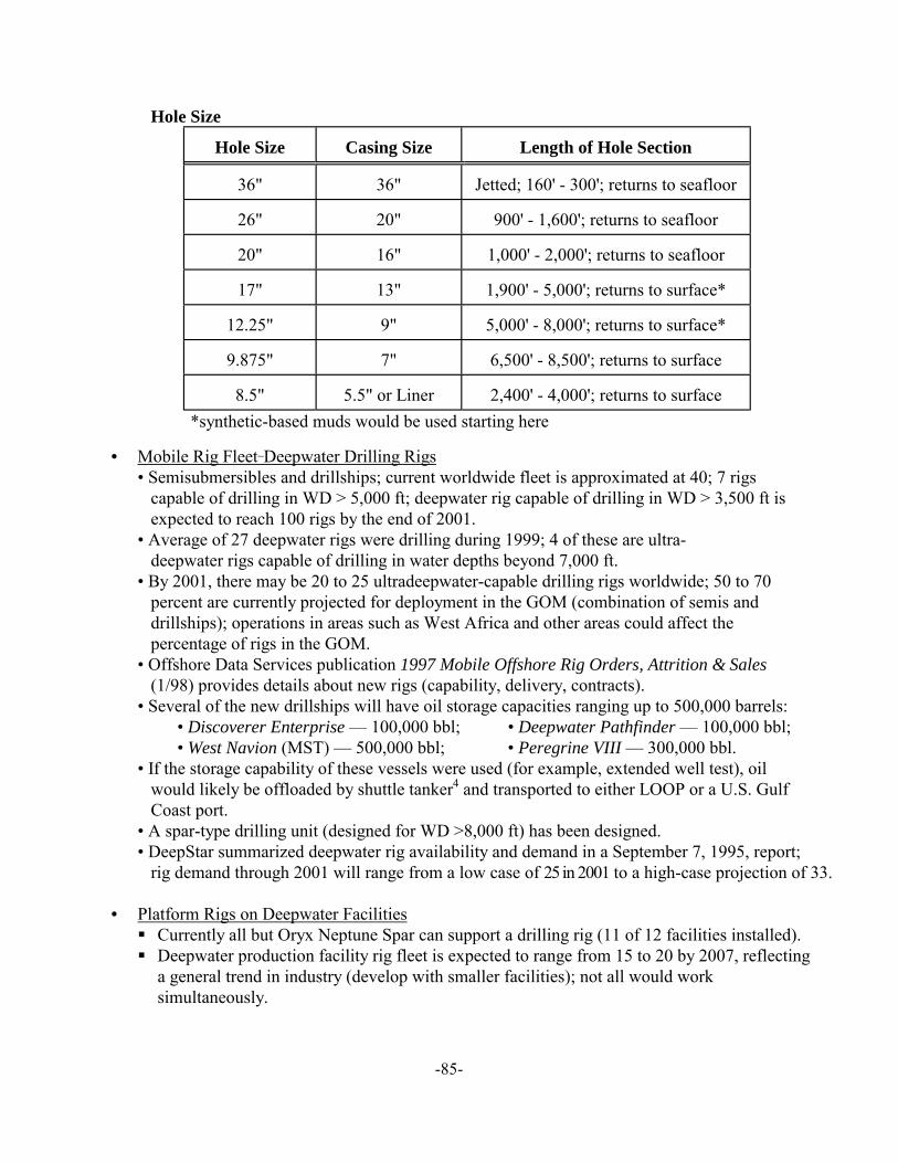
-85-
Hole Size
Hole Size Casing Size Length of Hole Section
36" 36" Jetted; 160' - 300'; returns to seafloor
26" 20" 900' - 1,600'; returns to seafloor
20" 16" 1,000' - 2,000'; returns to seafloor
17" 13" 1,900' - 5,000'; returns to surface*
12.25" 9" 5,000' - 8,000'; returns to surface*
9.875" 7" 6,500' - 8,500'; returns to surface
8.5" 5.5" or Liner 2,400' - 4,000'; returns to surface
*synthetic-based muds would be used starting here
• Mobile Rig Fleet_Deepwater Drilling Rigs• Semisubmersibles and drillships; current worldwide fleet is approximated at 40; 7 rigs
capable of drilling in WD > 5,000 ft; deepwater rig capable of drilling in WD > 3,500 ft isexpected to reach 100 rigs by the end of 2001.
• Average of 27 deepwater rigs were drilling during 1999; 4 of these are ultra-deepwater rigs capable of drilling in water depths beyond 7,000 ft.
• By 2001, there may be 20 to 25 ultradeepwater-capable drilling rigs worldwide; 50 to 70percent are currently projected for deployment in the GOM (combination of semis anddrillships); operations in areas such as West Africa and other areas could affect thepercentage of rigs in the GOM.
• Offshore Data Services publication 1997 Mobile Offshore Rig Orders, Attrition & Sales(1/98) provides details about new rigs (capability, delivery, contracts).
• Several of the new drillships will have oil storage capacities ranging up to 500,000 barrels:• Discoverer Enterprise — 100,000 bbl; • Deepwater Pathfinder — 100,000 bbl;• West Navion (MST) — 500,000 bbl; • Peregrine VIII — 300,000 bbl.
• If the storage capability of these vessels were used (for example, extended well test), oilwould likely be offloaded by shuttle tanker4 and transported to either LOOP or a U.S. GulfCoast port.
• A spar-type drilling unit (designed for WD >8,000 ft) has been designed.• DeepStar summarized deepwater rig availability and demand in a September 7, 1995, report;
rig demand through 2001 will range from a low case of 25 in 2001 to a high-case projection of 33.
• Platform Rigs on Deepwater Facilities! Currently all but Oryx Neptune Spar can support a drilling rig (11 of 12 facilities installed).! Deepwater production facility rig fleet is expected to range from 15 to 20 by 2007, reflecting
a general trend in industry (develop with smaller facilities); not all would worksimultaneously.
-86-
Existing Deepwater Production Infrastructure• As of January 1, 1998, there were 23 deepwater producing fields (Table 3):
! 6 fixed platforms, 6 floating facilities, 11 subsea developments tied back to host.! >50 percent are concentrated around the Mississippi River delta (GC, MC, VK areas).
• Existing Major Hubs/Hosts5 (may not be an exhaustive list):! WD 143! ST 300 Cougar)! EW 873! GB 426 (Auger)! GC 18
! WD 152! GC 65 (Bullwinkle)! MC 807 (Mars)! VK 956 (Ram-Powell)! MP 252
! SS 332! SS 349 (Mahogany)! VK 989 (Pompano)! GC 6! GB 189
Future Facilities/Activities• There are 63 discoveries either under construction or at the planning or evaluation stage of
development; here is the area breakout for these discoveries/developments:! MC __ 22! GC __ 13! GB __ 11
! EW __ 6 ! VK __ 4! EB __ 3
! DC __ 1! AT __ 1
• 50 to 60 deepwater projects are likely to be under development or producing by 2007 (highcase of 90). These will range from small subsea developments to large, multiwelldevelopments associated with the different floating production systems, fixed platforms, andsubsea facilities.
• Table 4 lists the range of projects by year:! 50 to 70 subsea tiebacks to host.! 3 to 8 fixed facilities (compliant towers, conventional jackets).! 15 to 35 floating systems (TLP’s, Spars, FPUs’); water depths between 1,000 ft and
7,000 ft.! 2 to 5 FPSO’s are projected to be installed in GC/GB/MC areas (WD > 3,000 ft),
beginning in 2001, each supported by 500,000-bbl shuttle tankers (1-2 per FPSO)6
! Years 2003 to 2007 — 65/35 split (subsea to other systems).• Expect 10 to 15 discoveries announced per year through 2007• Several innovative designs for production facilities will be introduced to the GOM during
the next decade (variations of spars, TLP’s, mini-TLP’s, etc.); there is also expected to bethe application of existing systems and technology beyond their current rated capabilities(based on experience, evaluations, and analysis).
• Additional (possible/projected) hub/host facilities and outpost7 developments (1998-2010):! GB 260 (Baldpate)! AC 26 (Hoover)! MC 85 (King)! MC 809 (Ursa)! 2 others in GB/EB area! 2 in Atwater area
! VK 786 (Petronius)! GC 65 (Bullwinkle)! MC 711 (Gomez)! GC 205 (Genesis)! 2 in Alaminos Canyon area! 1 in Keathley Canyon
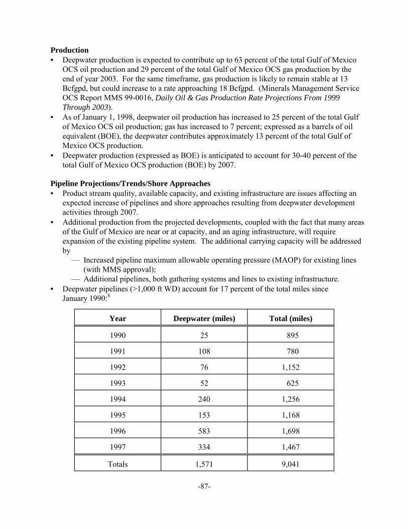
-87-
Production• Deepwater production is expected to contribute up to 63 percent of the total Gulf of Mexico
OCS oil production and 29 percent of the total Gulf of Mexico OCS gas production by theend of year 2003. For the same timeframe, gas production is likely to remain stable at 13Bcfgpd, but could increase to a rate approaching 18 Bcfgpd. (Minerals Management ServiceOCS Report MMS 99-0016, Daily Oil & Gas Production Rate Projections From 1999Through 2003).
• As of January 1, 1998, deepwater oil production has increased to 25 percent of the total Gulfof Mexico OCS oil production; gas has increased to 7 percent; expressed as a barrels of oilequivalent (BOE), the deepwater contributes approximately 13 percent of the total Gulf ofMexico OCS production.
• Deepwater production (expressed as BOE) is anticipated to account for 30-40 percent of thetotal Gulf of Mexico OCS production (BOE) by 2007.
Pipeline Projections/Trends/Shore Approaches• Product stream quality, available capacity, and existing infrastructure are issues affecting an
expected increase of pipelines and shore approaches resulting from deepwater developmentactivities through 2007.
• Additional production from the projected developments, coupled with the fact that many areasof the Gulf of Mexico are near or at capacity, and an aging infrastructure, will requireexpansion of the existing pipeline system. The additional carrying capacity will be addressedby
— Increased pipeline maximum allowable operating pressure (MAOP) for existing lines(with MMS approval);
— Additional pipelines, both gathering systems and lines to existing infrastructure.• Deepwater pipelines (>1,000 ft WD) account for 17 percent of the total miles since
January 1990:8
Year Deepwater (miles) Total (miles)
1990 25 895
1991 108 780
1992 76 1,152
1993 52 625
1994 240 1,256
1995 153 1,168
1996 583 1,698
1997 334 1,467
Totals 1,571 9,041
-88-
• Deepwater pipeline “miles installed” is expected to range between 300 and 500 miles peryear through 2007.9 Pre-1996 low number of pipeline miles was due to operatorinstallation on a project-specific need. Other reasons for the low number of pipeline milesprior to 1996 include replacement of outdated lines with new, larger lines (same corridors)and equipment constraints (available equipment is limited). Beginning 1996, the increasednumber of deepwater development projects and the shift to installations by operators(instead of transmission companies) is assumed to be the reason for a steady increase inmiles of pipeline installed.
• Several notable oil and gas pipeline systems (gathering and transmission lines) with shoreapproaches can be projected, based on the number of expected development projects duringthe next decade, including:
! from the Main Pass area (servicing Viosca Knoll, northern Mississippi Canyon);! from the Garden Banks area (could be more than one);! from the Green Canyon and southern Mississippi Canyon areas;! Diana/Hoover oil line (from Alaminos Canyon Block 25)__shore approach at Texas City! from the Western GOM (servicing East Breaks, Alaminos Canyon, Garden Banks, and
Keathley Canyon)These systems will likely be built with excess capacity to allow for additional field tie-ins.
Alternate Transportation• Two to three FPSO’s operating in the GOM would each be supported by as many as two
500,000-barrel shuttle tankers; assumed operation would be processing 100,000 BOPD withoffloading occurring approximately every five days.
• Oil would be transported to LOOP or one of five Gulf Coast ports such as Lake Charles.10
Abandonment Strategies11
Delayed abandonment of major facilities is likely as additional fields are tied into infrastructure;some of these will become hosts or production hubs (refer to list under “Future Facilities” above),while others will continue to produce as infill drilling starts up throughout the life of the field. Listed below are the likely abandonment strategies for deepwater developments:• Subsea
! Wells — plug in accordance with 30 CFR 250, Subpart G.! Pipeline and umbilical — decommission (cleaned and capped), leave on seafloor.! Subsea production tree — retrieve.! Well jumpers — retrieve.! Seafloor structures (manifold, template) — abandon in place or retrieve.
• TLP! Hull — remove from field for salvage or reuse.! Mooring — remove for salvage.! Tendon piles — remove or abandon in place.! Wells — plug in accordance with 30 CFR 250, Subpart G.! Production riser — remove to shore for salvage.! Pipeline — decommission (cleaned and capped), leave on seafloor.
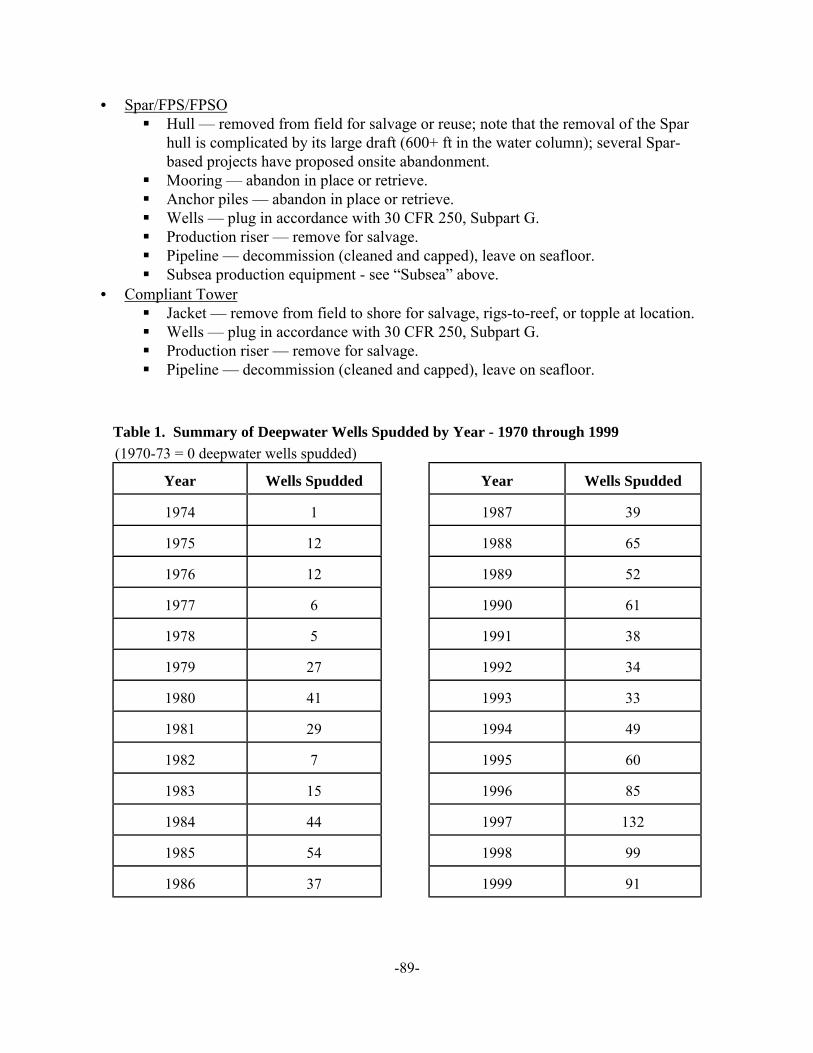
-89-
• Spar/FPS/FPSO! Hull — removed from field for salvage or reuse; note that the removal of the Spar
hull is complicated by its large draft (600+ ft in the water column); several Spar-based projects have proposed onsite abandonment.
! Mooring — abandon in place or retrieve.! Anchor piles — abandon in place or retrieve.! Wells — plug in accordance with 30 CFR 250, Subpart G.! Production riser — remove for salvage.! Pipeline — decommission (cleaned and capped), leave on seafloor.! Subsea production equipment - see “Subsea” above.
• Compliant Tower! Jacket — remove from field to shore for salvage, rigs-to-reef, or topple at location.! Wells — plug in accordance with 30 CFR 250, Subpart G.! Production riser — remove for salvage.! Pipeline — decommission (cleaned and capped), leave on seafloor.
Table 1. Summary of Deepwater Wells Spudded by Year - 1970 through 1999
(1970-73 = 0 deepwater wells spudded)
Year Wells Spudded Year Wells Spudded
1974 1 1987 39
1975 12 1988 65
1976 12 1989 52
1977 6 1990 61
1978 5 1991 38
1979 27 1992 34
1980 41 1993 33
1981 29 1994 49
1982 7 1995 60
1983 15 1996 85
1984 44 1997 132
1985 54 1998 99
1986 37 1999 91
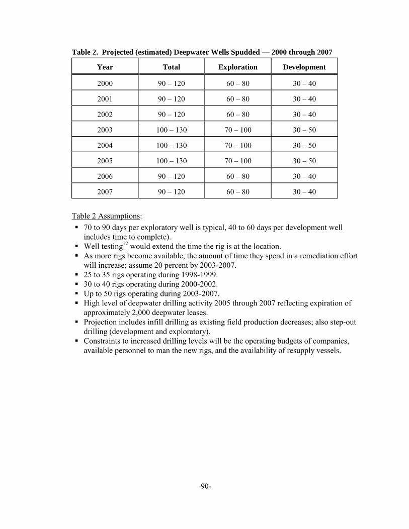
-90-
Table 2. Projected (estimated) Deepwater Wells Spudded — 2000 through 2007
Year Total Exploration Development
2000 90 – 120 60 – 80 30 – 40
2001 90 – 120 60 – 80 30 – 40
2002 90 – 120 60 – 80 30 – 40
2003 100 – 130 70 – 100 30 – 50
2004 100 – 130 70 – 100 30 – 50
2005 100 – 130 70 – 100 30 – 50
2006 90 – 120 60 – 80 30 – 40
2007 90 – 120 60 – 80 30 – 40
Table 2 Assumptions:
! 70 to 90 days per exploratory well is typical, 40 to 60 days per development wellincludes time to complete).
! Well testing12 would extend the time the rig is at the location.! As more rigs become available, the amount of time they spend in a remediation effort
will increase; assume 20 percent by 2003-2007.! 25 to 35 rigs operating during 1998-1999.! 30 to 40 rigs operating during 2000-2002.! Up to 50 rigs operating during 2003-2007.! High level of deepwater drilling activity 2005 through 2007 reflecting expiration of
approximately 2,000 deepwater leases.! Projection includes infill drilling as existing field production decreases; also step-out
drilling (development and exploratory).! Constraints to increased drilling levels will be the operating budgets of companies,
available personnel to man the new rigs, and the availability of resupply vessels.
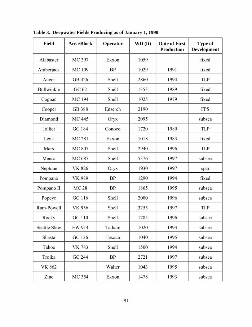
-91-
Table 3. Deepwater Fields Producing as of January 1, 1998
Field Area/Block Operator WD (ft) Date of FirstProduction
Type ofDevelopment
Alabaster MC 397 Exxon 1059 fixed
Amberjack MC 109 BP 1029 1991 fixed
Auger GB 426 Shell 2860 1994 TLP
Bullwinkle GC 62 Shell 1353 1989 fixed
Cognac MC 194 Shell 1025 1979 fixed
Cooper GB 388 Enserch 2190 FPS
Diamond MC 445 Oryx 2095 subsea
Jolliet GC 184 Conoco 1720 1989 TLP
Lena MC 281 Exxon 1018 1983 fixed
Mars MC 807 Shell 2940 1996 TLP
Mensa MC 687 Shell 5376 1997 subsea
Neptune VK 826 Oryx 1930 1997 spar
Pompano VK 989 BP 1290 1994 fixed
Pompano II MC 28 BP 1865 1995 subsea
Popeye GC 116 Shell 2000 1996 subsea
Ram-Powell VK 956 Shell 3255 1997 TLP
Rocky GC 110 Shell 1785 1996 subsea
Seattle Slew EW 914 Tatham 1020 1993 subsea
Shasta GC 136 Texaco 1040 1995 subsea
Tahoe VK 783 Shell 1500 1994 subsea
Troika GC 244 BP 2721 1997 subsea
VK 862 Walter 1043 1995 subsea
Zinc MC 354 Exxon 1478 1993 subsea
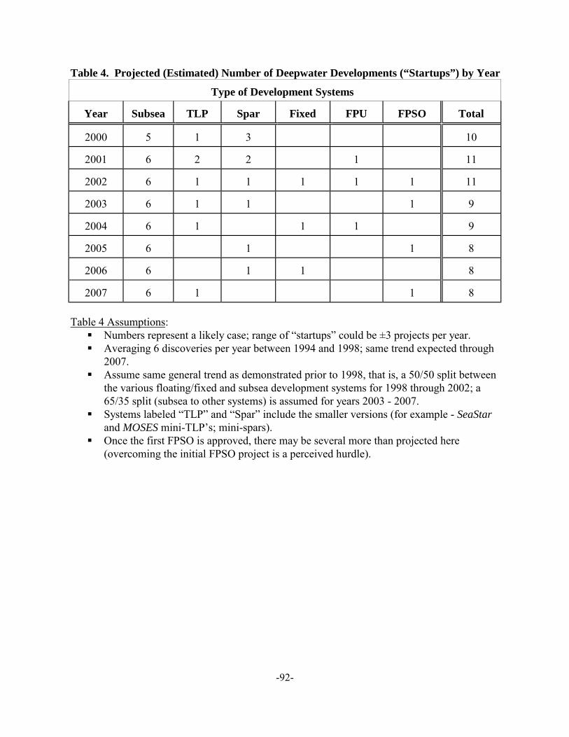
-92-
Table 4. Projected (Estimated) Number of Deepwater Developments (“Startups”) by Year
Type of Development Systems
Year Subsea TLP Spar Fixed FPU FPSO Total
2000 5 1 3 10
2001 6 2 2 1 11
2002 6 1 1 1 1 1 11
2003 6 1 1 1 9
2004 6 1 1 1 9
2005 6 1 1 8
2006 6 1 1 8
2007 6 1 1 8
Table 4 Assumptions:! Numbers represent a likely case; range of “startups” could be ±3 projects per year.! Averaging 6 discoveries per year between 1994 and 1998; same trend expected through
2007.! Assume same general trend as demonstrated prior to 1998, that is, a 50/50 split between
the various floating/fixed and subsea development systems for 1998 through 2002; a65/35 split (subsea to other systems) is assumed for years 2003 - 2007.
! Systems labeled “TLP” and “Spar” include the smaller versions (for example - SeaStarand MOSES mini-TLP’s; mini-spars).
! Once the first FPSO is approved, there may be several more than projected here(overcoming the initial FPSO project is a perceived hurdle).
-93-
Endnotes
1 Cycle time is strongly dependent on infrastructure and equipment and technology; 7.5years now are likely because of the lack of these prior to the mid- to late 1990's. As developmentprojects move into deeper water (for example, Mensa), this cycle time may be reduced to 3-4years (or more) as technology and techniques are proved successful.
2 The number of wells drilled does not distinguish sidetracks out of the existing wellboreas separate wells (for purposes of this report, only a separate surface (seafloor) location would beconsidered a separate well).
3 Statistical information provided by Shell for all operators in GOM, WD > 1,500 ft: 338exploratory wells, 85 development wells (Shell-specific: 92 exploratory, 46 development); MMSdata indicate 2:1 ratio (exploratory to development), but the accuracy of data in our TIMS systemis suspect as it relates to the well type flag.
4 Expected day rate for these new drillships would likely prevent them from operating asa transport vessel, as would Jones Act considerations (U.S. flag requirements). Another limitingfactor is the draft of these vessels; at 45 to 48 ft, they would not be able to enter U.S. Gulf Coastports.
5 Major hub/host does not imply that all remote subsea developments tie back to thesefacilities. There are many host facilities that have been designated for subsea developments;these are typically close to the subsea well(s) and may be owned by the company or a partner inthe subsea project. The difference here is recognition of those facilities that could require majorupgrades (increased capacity for processing) or will support several subsea development projects. Many of the hubs will require little increased capacity since the timing of bringing a subsea wellinto production would be linked to a need to offset declining production at the facility.
6 Details about FPSO’s can be found in Section I, Chapter 6 of this paper.
7 Outpost development as used here is a major development project that is remote fromexisting infrastructure. Such a project is likely to open opportunities for other developmentprojects in the vicinity (40-mile radius). Two examples are Exxon’s Diana/Hoover (EB/AC) andShell’s Mensa (MC).
8Reference paper “Regulatory Issues and Deepwater Production” (Alvarado, MMS),presented at the 1998 Deepwater Pipeline Conference, New Orleans.
9Existing system capacity could be expanded by installing additional compressor orbooster stations; however, this is not expected to change the projection.
10 Refer to USCG Deepwater, Port Study, Office of Maritime Safety, Security,Environmental Petroleum, PB 94-124054.
11 Abandonment strategies are extracted from Deepwater Operation Plans; addressed byoperators as options; an operator must obtain MMS approval of the abandonment strategy.
-94-
12 A distinction is made between extended well testing and early production. As part ofMMS’s interaction with DeepStar in Phase II, well testing in the GOM was described as follows:
Extended well testing is an engineering tool that would likely be conducted from thefloating drilling unit to evaluate the reservoir’s productivity (flow characteristics, etc., and wouldlikely involve a single well. Such a test also provides an opportunity to obtain information thatwould be used to design the production facilities. A typical extended well test might last for twoweeks to two months, of which the well would flow hydrocarbons only a few days. The wellwould be shut in for the remainder of the test to measure the reservoir’s response to production.
Early production is the first phase of continuous production, conducted at a small scale(1-3 wells) and designed to demonstrate long-term reservoir productivity. Information from earlyproduction would be used for decisions about sizing the full development system facilities. Theearly production phase could also be used to generate revenues while the full-phase productionequipment is readied for installation. Early production could last from two months to two years.