Embed Size (px)
Citation preview
48 Int. J. Mechatronics and Automation, Vol. 3, No. 1, 2013
Copyright © 2013 Inderscience Enterprises Ltd.
A reconfigurable modular fixture design for meso-milling
Gelareh Namdar*, Chen Liu, James K. Mills and Beno Benhabib Department of Mechanical and Industrial Engineering, University of Toronto, Toronto, Ontario, M5S 3G8, Canada E-mail: [email protected] E-mail: [email protected] E-mail: [email protected] E-mail: [email protected] *Corresponding author
Abstract: A reconfigurable, intelligent modular fixture with embedded sensing capabilities is critical to improving the adaptability and efficiency of meso-milling machines for yielding micro-size features. The primary goals in designing such a fixture are: 1) to locate a large group of similar workpieces with minimal setup changes; 2) to sense the location of a workpiece placed on the fixture; 3) to provide feedback in regard to ongoing proper workholding of a workpiece during machining. We consider two specific issues to address these goals. First, designing a set of modular fixture components with desired stiffness and accuracy. Second, employing miniaturised and accurate embedded sensors.
Keywords: meso-milling; reconfigurable intelligent fixtures; embedded sensors.
Reference to this paper should be made as follows: Namdar, G., Liu, C., Mills, J.K. and Benhabib, B. (2013) ‘A reconfigurable modular fixture design for meso-milling’, Int. J. Mechatronics and Automation, Vol. 3, No. 1, pp.48–57.
Biographical notes: Gelareh Namdar received her Master’s in Mechanical Engineering from the University of Toronto. Her research focused on conceptual design of reconfigurable, intelligent fixtures with embedded sensors for meso-milling at the Computer Integrated Manufacturing Laboratory. She is currently working in the automotive industry with a focus on problem solving and risk management.
Chen Liu graduated from Mechanical Engineering from the University of Toronto in 2010 with BASc degree. From 2010 to 2011, her research focused on modular fixture designs at the Computer Integrated Manufacturing Laboratory. Her current research is focused on deep learning, pattern recognition and computer vision.
James K. Mills is with the Department of Mechanical Engineering, University of Toronto. His recent research interests include: control of multi-robots, design and control of high speed machines, 3D MEMS robotic assembly and micro-scale biological task automation. He has published over 400 papers and supervised over 60 Masters and PhD students and a number of Post-Doctoral Fellows and research engineers. He has been an Invited Visiting Professor at the Centre for Artificial Intelligence and Robotics in Bangalore, India, a Visiting Professor at the Hong Kong University of Science and Technology, Chinese University of Hong Kong and the City University, Hong Kong.
Beno Benhabib is a Professor of Mechanical and Industrial Engineering at the University of Toronto since 1986. He is also cross-appointed to the Institute of Biomedical and Biomaterials Engineering at the University of Toronto. His research interests include autonomous systems, design and mathematical analysis of modular and multi-arm robots; machine vision; robotic sensors; supervisory control of manufacturing systems; and computer aided design of machine tools.
1 Introduction
During the past decade, the global demand for meso-scale production, in applications such as in-vivo biomedical
devices, portable electronics, and precision tools has increased (Luo et al., 2005). Meso-scale parts (0.5 to 5 mm in size) are expected to have sub-micron accuracies. A
A reconfigurable modular fixture design for meso-milling 49
fixturing system for meso-milling would, thus, require an accuracy level an order of magnitude better than that of the machine itself.
Currently, most commercial meso-milling systems use either simple locating/clamping systems or standard dedicated fixture devices. This approach can satisfy the basic functional requirements of a meso-milling machine. However, using dedicated fixtures leads to several limitations, including prohibitive cost of fixtures and long lead-times, especially for one-of-a-kind and small batch-sized parts, and lack of intelligence in terms of sensing. The main motivation behind this research is, thus, to design a reconfigurable fixture with embedded sensors that improves the adaptability and efficiency of meso-milling machines through workholding modularity. Thus, it is desirable that the proposed fixturing system can locate the workpieces rapidly, repeatably, and with sufficient accuracy.
The modularity, stiffness as well as load capacity of such fixtures are important characteristics since they cause limitations on the locating accuracy and suitability for different parts. Thus, there is an immediate need for the development of intelligent, meso-scale, modular fixtures. In this work, we aim to present a conceptual design of a new intelligent reconfigurable fixturing system incorporated with smart-material sensors from both mechanical design and sensor design perspectives.
The concept of the fixture modularity was first developed in the 1960s for the machine-tool manufacturing industry. These fixtures consisted of kits of standard modular components (i.e., locators, V-blocks, and clamps) assembled and reconfigured manually on a baseplate in order to locate and hold different sizes of workpiece, mostly for one-of-a-kind and small batch production. There was no feedback information provided (Gallien and Hammer, 1984). The available non-programmable fixtures consisted of the passive modular components, designed to be manually/automatically (i.e., by a robot) configured on a T-slot or a hole-type baseplate.
In 1986, Colbert et al. developed an automatic modular fixturing system including a baseplate, tool point units, and clamps, for the machining of prismatic workpieces (Colbert et al., 1986; Colbert, 1985). The fixture was capable of being loaded and unloaded by a robot and also sense the existence of the workpiece for initiating an automatic clamping sequence and then releasing the workpiece after it is machined. The tool point unit was equipped with a microswitch activated by the motion of the tool point when in contact with the workpiece.
In 1989, Chan et al. (1990) developed a modular programmable fixturing system for the automatic assembly of regular-sized parts including a horizontal locator, a variable-height vertical locator, a variable-wide V-block, a universal clamp, and a hole-type baseplate. All the components were flexible in the sense that they could be used for workpieces with different sizes and geometries. All fixture components were also embedded with optical
sensors. The component/baseplate interface was also standardised.
Currently, most of the commercial meso-milling systems use standardised, off-the-shelf fixture devices. This approach can satisfy the basic functional requirements of a meso-milling machine and reduce the fabrication cost of the specialised fixture. However, having a standardised system would lead to several limitations on the shape of the workpiece, and would reduce the usage efficiency and machinability of the workpieces.
Although meso-milling machines focus on different scales of components compared to the conventional milling machines, their fixturing principles are similar. As mentioned above, commercialised micro-milling systems, such as the one by Makino, Kern and Microlution have integrated the standard kinematic coupling base with tool chuck as a workholding system for their micro-milling machines. This method is also a common approach adopted by meso-milling researchers in academia. Honegger et al. (2006) describe a fixturing system used in the microfactory developed in UIUC as a pallet system that is incorporated with a kinematic coupling base. Sensors are placed underneath the base to perform direct measuring during operations.
In order to innovate upon the state-of-the-art technology and address one of the immediate needs of meso-scale machining, a new intelligent reconfigurable fixturing system incorporated with smart-material sensors is presented herein. The work will be presented with respect to two aspects of our research in the area:
1 mechanical design
2 sensor design.
One can note that, with respect to the first aspect, our goal has been to first establish the basic locating units and, thus, clamp design at the meso-scale level is not within the scope of this paper. We consider our proposed fixturing system as an intelligent one since it incorporates the basic building-block of intelligence in terms of sensing and closed-loop feedback control as previously discussed in Chan et al. (1990). Furthermore, the system is integrated with in-house designed hardware (circuitry for sensors) and control software.
2 Conceptual mechanical design
Traditional dowel-based system is selected as the (hole-based) baseplate concept for the meso-milling workholding system, considering the following primary requirements for the proposed design:
• Fixture components shall assist to locate workpieces and immobilise workpieces.
• The fixture shall be durable, resist shock and wear forces introduced during loading, locating and machining.
• Repeatability of locating shall be achieved at all times.
50 G. Namdar et al.
• The fixture shall tolerate small variations in tolerances of workpieces and not negatively affect the machining of the workpiece.
One can note that, general specifications for the meso-milling fixturing system with embedded sensors would also include the following:
• the fixture should be able to fix workpieces with 3D sculpted surfaces
• the workpiece dimensions could be in the range of 0.5 mm to 5 mm
• the positioning accuracy could be less than 0.1 micron
• the fixture components should be reconfigurable by robot with sensors embedded to detect the presence of workpiece.
Based on the above requirement, the proposed system includes: side locators, rest buttons, and V-blocks. Clamps are omitted in this initial attempt.
2.1 Locators
The proposed locator design is presented in Figure 1. The metal inner core uses alloy steel, which is partially coated with the insulating material and electrode. A polymeric sensor (piezoresistive) material is moulded around the neck area of the structural component. The circumference of the piezoresistive sensor is naturally larger than the metal structure core. When the workpiece is placed against the locator, piezoresistive material is compressed. Namely, the workpiece would be pushed against the piezoresistive material until it is stopped by the structural core. The structural core is a bone-shaped metal pillar, which is coated with electrode and insulating material. The piezoresistive sensor is moulded around the circumference of the pillar. The compressed piezoresistive sensor can, thus, be used for detecting the presence and proper locating of the workpiece, which will be further detailed in Section 4.
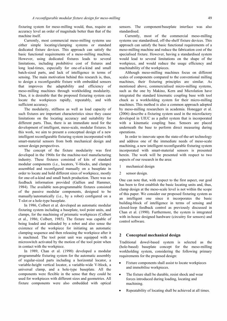
Figure 1 Design of side locator
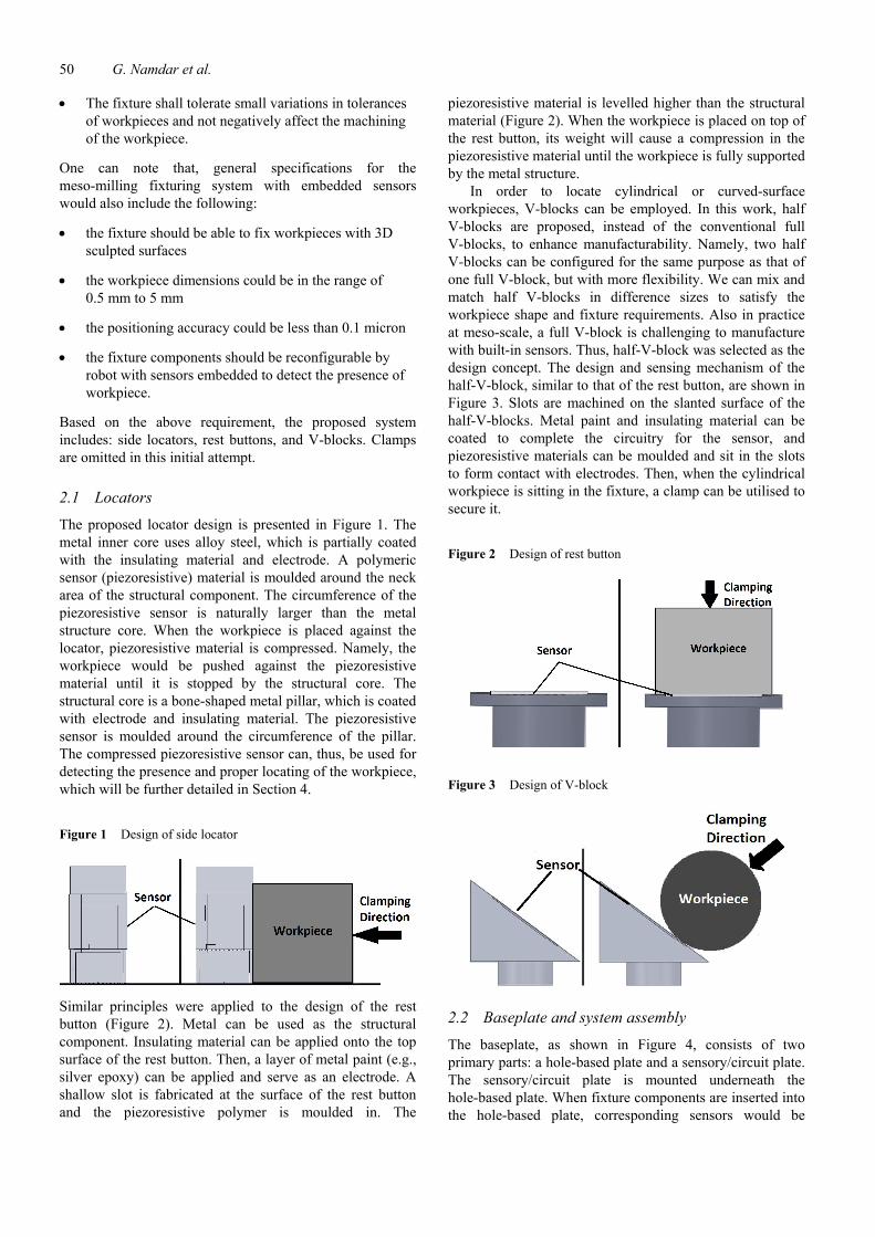
Similar principles were applied to the design of the rest button (Figure 2). Metal can be used as the structural component. Insulating material can be applied onto the top surface of the rest button. Then, a layer of metal paint (e.g., silver epoxy) can be applied and serve as an electrode. A shallow slot is fabricated at the surface of the rest button and the piezoresistive polymer is moulded in. The
piezoresistive material is levelled higher than the structural material (Figure 2). When the workpiece is placed on top of the rest button, its weight will cause a compression in the piezoresistive material until the workpiece is fully supported by the metal structure.
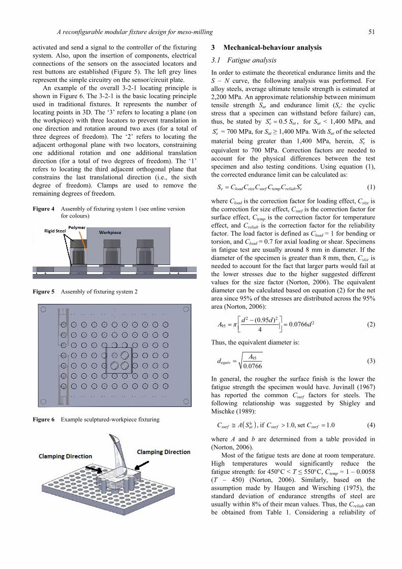
In order to locate cylindrical or curved-surface workpieces, V-blocks can be employed. In this work, half V-blocks are proposed, instead of the conventional full V-blocks, to enhance manufacturability. Namely, two half V-blocks can be configured for the same purpose as that of one full V-block, but with more flexibility. We can mix and match half V-blocks in difference sizes to satisfy the workpiece shape and fixture requirements. Also in practice at meso-scale, a full V-block is challenging to manufacture with built-in sensors. Thus, half-V-block was selected as the design concept. The design and sensing mechanism of the half-V-block, similar to that of the rest button, are shown in Figure 3. Slots are machined on the slanted surface of the half-V-blocks. Metal paint and insulating material can be coated to complete the circuitry for the sensor, and piezoresistive materials can be moulded and sit in the slots to form contact with electrodes. Then, when the cylindrical workpiece is sitting in the fixture, a clamp can be utilised to secure it.
Figure 2 Design of rest button
Figure 3 Design of V-block
2.2 Baseplate and system assembly
The baseplate, as shown in Figure 4, consists of two primary parts: a hole-based plate and a sensory/circuit plate. The sensory/circuit plate is mounted underneath the hole-based plate. When fixture components are inserted into the hole-based plate, corresponding sensors would be
A reconfigurable modular fixture design for meso-milling 51
activated and send a signal to the controller of the fixturing system. Also, upon the insertion of components, electrical connections of the sensors on the associated locators and rest buttons are established (Figure 5). The left grey lines represent the simple circuitry on the sensor/circuit plate.
An example of the overall 3-2-1 locating principle is shown in Figure 6. The 3-2-1 is the basic locating principle used in traditional fixtures. It represents the number of locating points in 3D. The ‘3’ refers to locating a plane (on the workpiece) with three locators to prevent translation in one direction and rotation around two axes (for a total of three degrees of freedom). The ‘2’ refers to locating the adjacent orthogonal plane with two locators, constraining one additional rotation and one additional translation direction (for a total of two degrees of freedom). The ‘1’ refers to locating the third adjacent orthogonal plane that constrains the last translational direction (i.e., the sixth degree of freedom). Clamps are used to remove the remaining degrees of freedom.
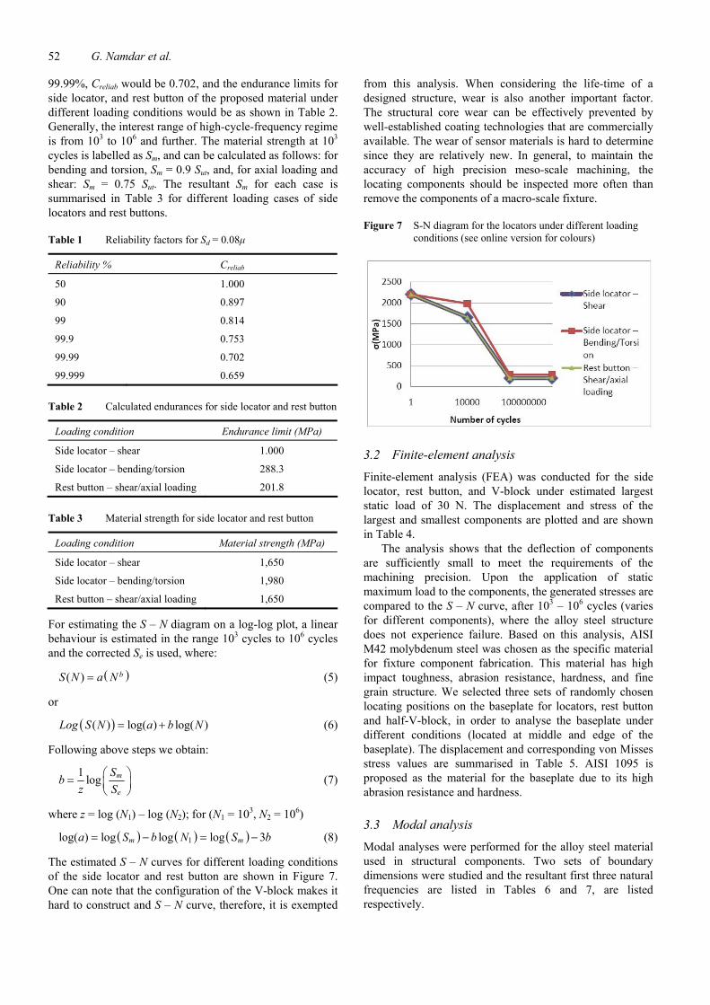
Figure 4 Assembly of fixturing system 1 (see online version for colours)
Figure 5 Assembly of fixturing system 2
Figure 6 Example sculptured-workpiece fixturing
3 Mechanical-behaviour analysis
3.1 Fatigue analysis
In order to estimate the theoretical endurance limits and the S – N curve, the following analysis was performed. For alloy steels, average ultimate tensile strength is estimated at 2,200 MPa. An approximate relationship between minimum tensile strength Sut and endurance limit (Se: the cyclic stress that a specimen can withstand before failure) can, thus, be stated by 0.5 ,e utS S′ = for Sut < 1,400 MPa, and
eS ′ = 700 MPa, for Sut ≥ 1,400 MPa. With Sut of the selected material being greater than 1,400 MPa, herein, eS ′ is equivalent to 700 MPa. Correction factors are needed to account for the physical differences between the test specimen and also testing conditions. Using equation (1), the corrected endurance limit can be calculated as:
e load size surf temp reliab eS C C C C C S ′= (1)
where Cload is the correction factor for loading effect, Csize is the correction for size effect, Csurf is the correction factor for surface effect, Ctemp is the correction factor for temperature effect, and Creliab is the correction factor for the reliability factor. The load factor is defined as Cload = 1 for bending or torsion, and Cload = 0.7 for axial loading or shear. Specimens in fatigue test are usually around 8 mm in diameter. If the diameter of the specimen is greater than 8 mm, then, Csize is needed to account for the fact that larger parts would fail at the lower stresses due to the higher suggested different values for the size factor (Norton, 2006). The equivalent diameter can be calculated based on equation (2) for the net area since 95% of the stresses are distributed across the 95% area (Norton, 2006):
2 22
95(0.95 ) 0.0766
4d dA π d−⎡ ⎤
= =⎢ ⎥⎣ ⎦ (2)
Thus, the equivalent diameter is:
95
0.0766equivAd = (3)
In general, the rougher the surface finish is the lower the fatigue strength the specimen would have. Juvinall (1967) has reported the common Csurf factors for steels. The following relationship was suggested by Shigley and Mischke (1989):
( ) , if 1.0, set 1.0bsurf surf surfutC A S C C≅ > = (4)
where A and b are determined from a table provided in (Norton, 2006).
Most of the fatigue tests are done at room temperature. High temperatures would significantly reduce the fatigue strength: for 450°C < T ≤ 550°C, Ctemp = 1 – 0.0058 (T – 450) (Norton, 2006). Similarly, based on the assumption made by Haugen and Wirsching (1975), the standard deviation of endurance strengths of steel are usually within 8% of their mean values. Thus, the Creliab can be obtained from Table 1. Considering a reliability of
52 G. Namdar et al.
99.99%, Creliab would be 0.702, and the endurance limits for side locator, and rest button of the proposed material under different loading conditions would be as shown in Table 2. Generally, the interest range of high-cycle-frequency regime is from 103 to 106 and further. The material strength at 103 cycles is labelled as Sm, and can be calculated as follows: for bending and torsion, Sm = 0.9 Sut, and, for axial loading and shear: Sm = 0.75 Sut. The resultant Sm for each case is summarised in Table 3 for different loading cases of side locators and rest buttons.
Table 1 Reliability factors for Sd = 0.08μ
Reliability % Creliab
50 1.000
90 0.897
99 0.814
99.9 0.753
99.99 0.702
99.999 0.659
Table 2 Calculated endurances for side locator and rest button
Loading condition Endurance limit (MPa)
Side locator – shear 1.000
Side locator – bending/torsion 288.3
Rest button – shear/axial loading 201.8
Table 3 Material strength for side locator and rest button
Loading condition Material strength (MPa)
Side locator – shear 1,650
Side locator – bending/torsion 1,980
Rest button – shear/axial loading 1,650
For estimating the S – N diagram on a log-log plot, a linear behaviour is estimated in the range 103 cycles to 106 cycles and the corrected Se is used, where:
( )( ) bS N a N= (5)
or
( )( ) log( ) log( )Log S N a b N= + (6)
Following above steps we obtain:
1 log m
e
Sbz S
⎛ ⎞= ⎜ ⎟⎝ ⎠
(7)
where z = log (N1) – log (N2); for (N1 = 103, N2 = 106)
( ) ( ) ( )1log( ) log log log 3m ma S b N S b= − = − (8)
The estimated S – N curves for different loading conditions of the side locator and rest button are shown in Figure 7. One can note that the configuration of the V-block makes it hard to construct and S – N curve, therefore, it is exempted
from this analysis. When considering the life-time of a designed structure, wear is also another important factor. The structural core wear can be effectively prevented by well-established coating technologies that are commercially available. The wear of sensor materials is hard to determine since they are relatively new. In general, to maintain the accuracy of high precision meso-scale machining, the locating components should be inspected more often than remove the components of a macro-scale fixture.
Figure 7 S-N diagram for the locators under different loading conditions (see online version for colours)
3.2 Finite-element analysis
Finite-element analysis (FEA) was conducted for the side locator, rest button, and V-block under estimated largest static load of 30 N. The displacement and stress of the largest and smallest components are plotted and are shown in Table 4.
The analysis shows that the deflection of components are sufficiently small to meet the requirements of the machining precision. Upon the application of static maximum load to the components, the generated stresses are compared to the S – N curve, after 103 – 106 cycles (varies for different components), where the alloy steel structure does not experience failure. Based on this analysis, AISI M42 molybdenum steel was chosen as the specific material for fixture component fabrication. This material has high impact toughness, abrasion resistance, hardness, and fine grain structure. We selected three sets of randomly chosen locating positions on the baseplate for locators, rest button and half-V-block, in order to analyse the baseplate under different conditions (located at middle and edge of the baseplate). The displacement and corresponding von Misses stress values are summarised in Table 5. AISI 1095 is proposed as the material for the baseplate due to its high abrasion resistance and hardness.
3.3 Modal analysis
Modal analyses were performed for the alloy steel material used in structural components. Two sets of boundary dimensions were studied and the resultant first three natural frequencies are listed in Tables 6 and 7, are listed respectively.
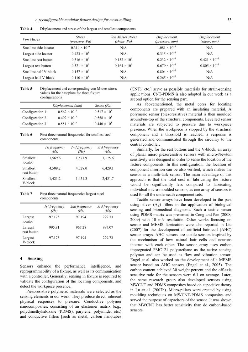
A reconfigurable modular fixture design for meso-milling 53
Table 4 Displacement and stress of the largest and smallest components
Von Misses Stress (pressure, Pa)
Von Misses stress (shear, Pa)
Displacement (pressure, mm)
Displacement (shear, mm)
Smallest side locator 0.314 × 10¹⁰ N/A 1.081 × 10⁻³ N/A Largest side locator 0.423 × 10⁸ N/A 0.315 × 10⁻³ N/A Smallest rest button 0.516 × 10⁹ 0.152 × 10⁹ 0.232 × 10⁻³ 0.421 × 10⁻⁵ Largest rest button 0.521 × 10⁹ 0.164 × 10⁹ 0.679 × 10⁻³ 0.805 × 10⁻⁵ Smallest half-V-block 0.157 × 10⁹ N/A 0.804 × 10⁻⁵ N/A Largest half-V-block 0.110 × 10⁸ N/A 0.265 × 10⁻⁵ N/A
Table 5 Displacement and corresponding von Misses stress
values for the baseplate for three fixture configurations
Displacement (mm) Stress (Pa)
Configuration 1 0.562 × 10⁻³ 0.517 × 10⁸ Configuration 2 0.492 × 10⁻³ 0.558 × 10⁸ Configuration 3 0.551 × 10⁻³ 0.440 × 10⁸
Table 6 First three natural frequencies for smallest steel components
1st frequency (Hz)
2nd frequency (Hz)
3rd frequency (Hz)
Smallest locator
1,569.6 1,571.9 3,175.6
Smallest rest button
4,509.2 4,528.0 6,429.1
Smallest V-block
1,421.2 1,451.3 2,451.7
Table 7 First three natural frequencies largest steel components
1st frequency (Hz)
2nd frequency (Hz)
3rd frequency (Hz)
Largest locator
97.175 97.194 229.73
Largest rest button
995.81 967.28 987.07
Largest V-block
97.175 97.194 229.73
4 Sensing
Sensors enhance the performance, intelligence, and reprogrammability of a fixture, as well as its communication with a controller. Generally, sensing in fixture is required to validate the configuration of the locating components, and detect the workpiece presence.
Piezoresistive polymeric materials were selected as the sensing elements in our work. They produce direct, inherent physical responses to pressure. Conductive polymer nanocomposites, consisting of an elastomer matrix (e.g., polydimethylsiloxane (PDMS), parylene, polyimide, etc.) and conductive fillers [such as metal, carbon nanotubes
(CNT), etc.] serve as possible materials for strain-sensing applications. CNT-PDMS is also adapted in our work as a second option for the sensing part.
As abovementioned, the metal cores for locating components are prepared with an insulating material. A polymeric sensor (piezoresistive) material is then moulded around/on-top of the structural components. Levelled sensor materials are subjected to pressure due to workpiece presence. When the workpiece is stopped by the structural component and a threshold is reached, a response is generated and communicated through the circuitry to the central controller.
Similarly, for the rest buttons and the V-block, an array of planar micro piezoresistive sensors with micro-Newton sensitivity was designed in order to sense the location of the fixture components. In this configuration, the location of component insertion can be also verified, which makes the sensor as a multi-task sensor. The main advantage of this approach is that the total cost of fabricating the fixture would be significantly less compared to fabricating individual micro-moulded sensors, as one array of sensors is used for all the underneath component sets.
Tactile sensor arrays have been developed in the past using silver (Ag) fillers in the application of biological sensing and biomedical diagnosis. Such a tactile sensor using PDMS matrix was presented in Cong and Pan (2008, 2009) with 10 mN resolution. Other works focusing on sensor and MEMS fabrication were also reported in Liu (2007) for the development of artificial hair cell (AHC) sensor arrays. AHC sensors are tactile sensors inspired by the mechanism of how natural hair cells and neurons interact with each other. The sensor array uses carbon impregnated PMC121 polyurethane as the active sensing polymer and can be used as flow and vibration sensor. Engel et al. also worked on the development of a MEMS sensor based on AHC sensors (Engel et al., 2005). The carbon content achieved 30 weight percent and the off-axis sensitive ratio for the sensors were 6.1 on average. Later, the same research group also developed sensors using MWCNT and PDMS composites based on capacitive theory in Lu et al. (2007b). Micro-pillars were created by using moulding techniques on MWCNT-PDMS composites and served the purpose of capacitors of the sensor. It was shown that MWCNT has better sensitivity than do carbon-based sensors.
54 G. Namdar et al.
As presented in Lu et al. (2007a), an array of tactile sensors with a carbon polydimethylsiloxane (CPDMS) composite was produced. The dimensions of each active piezoresistor were 50 μm × 30 μm × 8 μm with a mushroom-shaped electrode. When the pressure was applied to the active piezoresistor, the carbon black particles would be dispersed and result in changing the resistance. The array showed a minimum detectable resistance change when force was greater than 50 μN. Using the aforementioned idea, Lu’s design was adapted in our work. In order to obtain improvement over the original design, it was desirable to change the composite material from CPDMS to CNTPDMS since the average gauge factor of CNT-PDMS is twice as CPDMS (Lu et al., 2007b). In addition, in order to reduce the fabrication complexity, the mushroom electrode was removed. Note that since the smallest detectable force is 50 μN, if a workpiece weight is less than 50 μN clamps forces can be used to trigger the sensor detection. In addition, a larger material stalk (to increase the weight) can be used to achieve the detectable required force (machining the small part on the bigger stalk and break it off).
5 Experiments
5.1 Preparation
CNTs-PDMS is a relatively new composite material and related experimental and theoretical fundamentals are not yet well-established. Thus, some preliminary characterisations for the composites were required before proceeding with sensor design. PDMS is non-conductive. The conductive behaviour of such composites is fully dependent on the CNTs filler and the interaction between CNTs within the PDMS matrix (to create conductive network), related to the weight ratio of the CNTs present in the composite, as well as the thickness (distance from one measurement surface to another) of the sample material.
The brand of the PDMS in our work was Sylgard 184, manufactured by Dow Corning Chemicals (Midland, MI). This PDMS has a density of 1.03 g/cm3, electrical conductivity of 8.3 × 10⁻¹⁵ S/cm and viscosity of 3,900 cp. Multi-wall carbon nanotubes (MWCNT) used in the experiments were supplied by CheapTubes Inc. (Brattleboro, VT). The MWCNTs have a reported diameter between 30-50 nm, an average length of 10–30 μm and a purity level of > 95 wt.%. The MWCNTs also have an electrical conductivity > 102 S/cm and a specific surface area > 110 m2/g. Sylgard 184 silicone elastomer base and curing agent were mixed with a 10:1 weight ratio initially. Then, the MWCNT were added and mixed mechanically to reach the desired filler concentration (8, 12, and 16 wt.%).
5.2 Sensor characterisation
The CNT-PDMS was placed in a vacuum chamber for 30 min at 25 mm Hg in order to remove air bubbles introduced during the mixing process. Sample composites were prepared using compression moulding technique.
A rectangular mould (23 × 15mm2 with two different thicknesses: 1 and 2 mm) was used for the preparation of samples for compressive piezoresistance characterisations. After weighing, mixing and degassing, the liquid CNT-PDMS was poured into the mould. Then, the material was compression moulded in a Carver heated press (model 4386, Carver Inc, Wabash IN) at 90°C at a pressure of 0.5 metric tons for cross-linking process to occur.
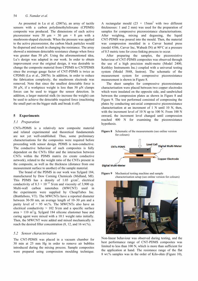
After preparing the samples, the piezoresistive behaviour of CNT-PDMS composites was observed through the use of a high precision multi-metre (Model 2400, Keithley Instruments Inc.) coupled with a universal testing system (Model 5848, Instron). The schematic of the measurement system for compressive piezoresistance measurement is shown in Figure 8.
The sheet samples for compressive piezoresistance characterisation were placed between two copper electrodes which were insulated on the opposite side, and sandwiched between the compression plates as shown in Figure 8 and Figure 9. The test performed consisted of compressing the plates by conducting uni-axial compressive piezoresistance characterisation at an increment of 1 N until 10 N, then, with the increment level of 10 N up to 100 N. From 100 N onward, the increment level changed until compression reached 400 N for examining the piezoresistance hypothesis.
Figure 8 Schematic of the measurements (see online version for colours)
Figure 9 Mechanical testing machine and sample characterisation setup (see online version for colours)
Non-linear behaviour was observed during testing, and the best performance range of CNT-PDMS composites was limited to less than 100 N, which is more than sufficient for the application at hand. The resistance range of the flat 8 wt.% samples was in the order of Kilo-ohm (Figure 10),
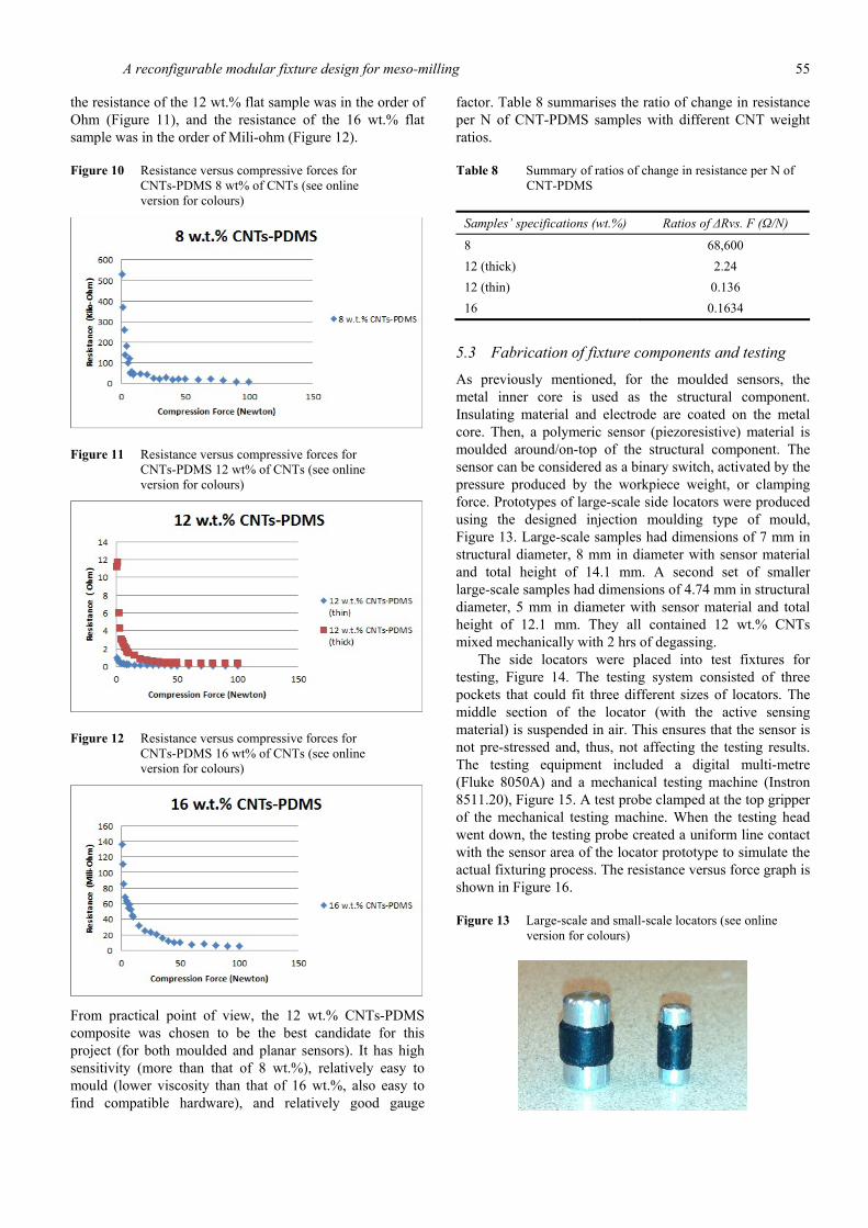
A reconfigurable modular fixture design for meso-milling 55
the resistance of the 12 wt.% flat sample was in the order of Ohm (Figure 11), and the resistance of the 16 wt.% flat sample was in the order of Mili-ohm (Figure 12).
Figure 10 Resistance versus compressive forces for CNTs-PDMS 8 wt% of CNTs (see online version for colours)
Figure 11 Resistance versus compressive forces for CNTs-PDMS 12 wt% of CNTs (see online version for colours)
Figure 12 Resistance versus compressive forces for CNTs-PDMS 16 wt% of CNTs (see online version for colours)
From practical point of view, the 12 wt.% CNTs-PDMS composite was chosen to be the best candidate for this project (for both moulded and planar sensors). It has high sensitivity (more than that of 8 wt.%), relatively easy to mould (lower viscosity than that of 16 wt.%, also easy to find compatible hardware), and relatively good gauge
factor. Table 8 summarises the ratio of change in resistance per N of CNT-PDMS samples with different CNT weight ratios.
Table 8 Summary of ratios of change in resistance per N of CNT-PDMS
Samples’ specifications (wt.%) Ratios of ΔRvs. F (Ω/N)
8 68,600 12 (thick) 2.24 12 (thin) 0.136 16 0.1634
5.3 Fabrication of fixture components and testing
As previously mentioned, for the moulded sensors, the metal inner core is used as the structural component. Insulating material and electrode are coated on the metal core. Then, a polymeric sensor (piezoresistive) material is moulded around/on-top of the structural component. The sensor can be considered as a binary switch, activated by the pressure produced by the workpiece weight, or clamping force. Prototypes of large-scale side locators were produced using the designed injection moulding type of mould, Figure 13. Large-scale samples had dimensions of 7 mm in structural diameter, 8 mm in diameter with sensor material and total height of 14.1 mm. A second set of smaller large-scale samples had dimensions of 4.74 mm in structural diameter, 5 mm in diameter with sensor material and total height of 12.1 mm. They all contained 12 wt.% CNTs mixed mechanically with 2 hrs of degassing.
The side locators were placed into test fixtures for testing, Figure 14. The testing system consisted of three pockets that could fit three different sizes of locators. The middle section of the locator (with the active sensing material) is suspended in air. This ensures that the sensor is not pre-stressed and, thus, not affecting the testing results. The testing equipment included a digital multi-metre (Fluke 8050A) and a mechanical testing machine (Instron 8511.20), Figure 15. A test probe clamped at the top gripper of the mechanical testing machine. When the testing head went down, the testing probe created a uniform line contact with the sensor area of the locator prototype to simulate the actual fixturing process. The resistance versus force graph is shown in Figure 16.
Figure 13 Large-scale and small-scale locators (see online version for colours)
56 G. Namdar et al.
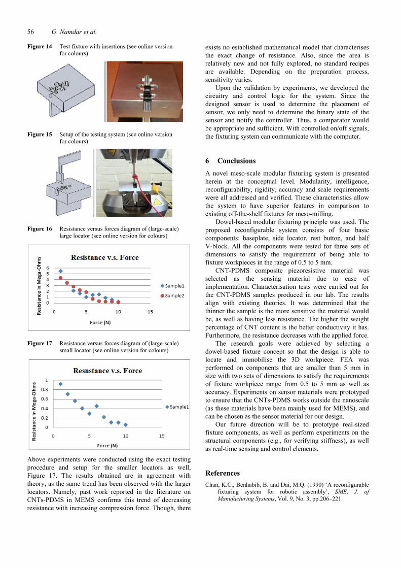
Figure 14 Test fixture with insertions (see online version for colours)
Figure 15 Setup of the testing system (see online version for colours)
Figure 16 Resistance versus forces diagram of (large-scale) large locator (see online version for colours)
Figure 17 Resistance versus forces diagram of (large-scale) small locator (see online version for colours)
Above experiments were conducted using the exact testing procedure and setup for the smaller locators as well, Figure 17. The results obtained are in agreement with theory, as the same trend has been observed with the larger locators. Namely, past work reported in the literature on CNTs-PDMS in MEMS confirms this trend of decreasing resistance with increasing compression force. Though, there
exists no established mathematical model that characterises the exact change of resistance. Also, since the area is relatively new and not fully explored, no standard recipes are available. Depending on the preparation process, sensitivity varies.
Upon the validation by experiments, we developed the circuitry and control logic for the system. Since the designed sensor is used to determine the placement of sensor, we only need to determine the binary state of the sensor and notify the controller. Thus, a comparator would be appropriate and sufficient. With controlled on/off signals, the fixturing system can communicate with the computer.
6 Conclusions
A novel meso-scale modular fixturing system is presented herein at the conceptual level. Modularity, intelligence, reconfigurability, rigidity, accuracy and scale requirements were all addressed and verified. These characteristics allow the system to have superior features in comparison to existing off-the-shelf fixtures for meso-milling.
Dowel-based modular fixturing principle was used. The proposed reconfigurable system consists of four basic components: baseplate, side locator, rest button, and half V-block. All the components were tested for three sets of dimensions to satisfy the requirement of being able to fixture workpieces in the range of 0.5 to 5 mm.
CNT-PDMS composite piezoresistive material was selected as the sensing material due to ease of implementation. Characterisation tests were carried out for the CNT-PDMS samples produced in our lab. The results align with existing theories. It was determined that the thinner the sample is the more sensitive the material would be, as well as having less resistance. The higher the weight percentage of CNT content is the better conductivity it has. Furthermore, the resistance decreases with the applied force.
The research goals were achieved by selecting a dowel-based fixture concept so that the design is able to locate and immobilise the 3D workpiece. FEA was performed on components that are smaller than 5 mm in size with two sets of dimensions to satisfy the requirements of fixture workpiece range from 0.5 to 5 mm as well as accuracy. Experiments on sensor materials were prototyped to ensure that the CNTs-PDMS works outside the nanoscale (as these materials have been mainly used for MEMS), and can be chosen as the sensor material for our design.
Our future direction will be to prototype real-sized fixture components, as well as perform experiments on the structural components (e.g., for verifying stiffness), as well as real-time sensing and control elements.
References Chan, K.C., Benhabib, B. and Dai, M.Q. (1990) ‘A reconfigurable
fixturing system for robotic assembly’, SME, J. of Manufacturing Systems, Vol. 9, No. 3, pp.206–221.
A reconfigurable modular fixture design for meso-milling 57
Colbert, J.L. (1985) Workholding Technology in Flexible Manufacturing and the Design of a Modular Fixturing System, MSc thesis, Rensselaer Polytechnic Institute, Troy, New York, August.
Colbert, J.L., Menassa, R. and DeVries, W.R. (1986) ‘A modular fixture for prismatic parts in an FMS’, SME, NAMRIC, pp.597–602.
Cong, H. and Pan, T. (2008) ‘Photopatternable conductive PDMS materials for microfabrication’, Adv. Funct. Mater., Vol. 18, No. 13, pp.1912–1921.
Cong, H. and Pan, T. (2009) ‘Microfabrication of conductive PDMS on flexible substrates for biomedical applications’, IEEE NEMS Conf. 2009, Shenzhen, China, January.
Engel, J.M., Chen, J., Bullen, D. and Liu, C. (2005) ‘Polyurethane rubber as a MEMS material: characterization and demonstration of an all-polymer two-axis artificial haircell flow sensor’, IEEE International Conference on MEMS, pp.279–282.
Gallien, D. and Hammer, H. (1984) ‘Efficient and cost effective use of modular fixture kits at the machine site’, TZ fur Metallbeatbeitung, Vol. 77, No. 5, pp.3–8.
Haugen, E.B. and Wirsching, P.H. (1975) ‘Probabilistic design’, Machine Design, Vol. 47, No. 12, pp.10–14.
Honegger, A.E., Langstaff, G.Q., Phillip, A.G., VanRavenswaay, T.D., Kapoor, S.G. and DeVor, R. (2006) ‘Development of an automated microfactory: part 1 – microfactory architecture and sub-systems development’, Transactions of NAMRIC/SME, Vol. 34, pp.333–340.
Juvinall, R.C. (1967) Stress, Strain and Strength, McGraw-Hall, New York, Figure 12.6, p.234.
Liu, C. (2007) ‘Micromachined biomimetic artificial haircell sensors’, Bioinspir. Biomim., Vol. 2, No. 4, pp.S162–S169.
Lu, J., Lu, M., Bermak, A. and Lee, Y.K. (2007a) ‘Study of piezoresistance effect of carbon nanotube-PDMS composite materials for nanosensors’, IEEE-NANO Conference, pp.1240–1243.
Lu, M., Bermak, A. and Lee, Y.K. (2007b) ‘Fabrication technology of piezoresistive conductive PDMS for micro fingerprint sensors’, IEEE 20th International Conference on MEMS, pp.251–254.
Luo, X., Cheng, C., Webb, D. and Wardle, F. (2005) ‘Design of ultraprecision machine tools with applications to the manufacture of miniature and micro components’, Journal of Materials Processing Technology, Vol. 167, p.521.
MicroManufacturing – Micromilling [online] http://www.micromanufacturing.net/didactico/Desarollo/ micromilling/.
Norton, R.L. (2006) Machine Design An Integrated Approach, 3rd ed., pp.326–327, Pearson Prentice Hall Pearson Education, Inc. Upper Saddle River NJ 07458, USA.
Shigley, J.E. and Mischke, C.R. (1989) Mechanical Engineering Design, 5th ed., p.283, Mc-Graw-Hill, New York.