Embed Size (px)
Citation preview
A real time SAR processor implementation with FPGA
C. Lesnik, A. Kawalec & P. Serafin Institute of Radioelectronics, Military University of Technology, Poland
Abstract
Great numerical complexity is a characteristic of synthetic aperture radar (SAR) image synthesis algorithms that poses a particularly serious problem for real-time application. Advances in the operating speed and density of the field programmable gate arrays (FPGA) have allowed many high-end signal processing applications to be solved in commercially available hardware. A real-time SAR image processor was designed and implemented with the commercial off the shelf (COTS) hardware. The hardware was based on the Xilinx Virtex 5 FPGA devices. Under the assumption of squinted SAR geometry and range migration effect present the SAR image synthesis algorithm was developed and implemented. The results of the processor tests conducted with simulated and real raw SAR signals are presented in the paper. Keywords: SAR, radar, real-time processing, FPGA, COTS.
1 Introduction
Airborne radar systems constitute the essential part of radio-electronic terrain imaging and recognition systems. Their primary advantage is the insensitivity to the time of the day or atmospheric conditions. However the images obtained by radar characterises much lower than in the photographic case resolution. In the radar imaging two resolutions can be distinguished: the range resolution called also the fast-time resolution and the azimuth or the slow-time resolution. If the task of achieving the high range resolution is relatively easy - it is realized by using sounding signals with internal frequency or phase modulation or manipulation, the high azimuth resolution is much harder to achieve. It
Computational Methods and Experimental Measurements XV 435
www.witpress.com, ISSN 1743-355X (on-line) WIT Transactions on Modelling and Simulation, Vol 51, © 2011 WIT Press
doi:10.2495/CMEM110381
requires specific and refined method of image synthesis called Synthetic Aperture Radar (SAR). This technique proved to be very useful in both civil and military applications. One of the many applications is the employment of a SAR sensor onboard Unmanned Aerial Vehicle (UAV) for an immediate terrain monitoring for industrial, military, antiterrorist and crisis management purposes. The specific nature of those areas of the practical use of a radar system requires the image synthesis to be performed in the real-time. The process of the radar image synthesis can be reduced to the two-dimensional matched filtration problem both in range and azimuth domains. There are a variety of different algorithms implementing this function such as Range-Doppler (RDA), Chirp Scaling (CSA), Omega-K, SPECAN or Time Domain Correlation (TDC) Algorithms. The last one is also called “the naive” algorithm. This one was described for example by Cumming and Wong [1] and Wang [2]. Those algorithms differ in accuracy and computational complexity. In this work the authors made an attempt at a real-time hardware implementation of the time domain matched filtration algorithm, which is often used as a reference algorithm due to its accuracy, and yet the one that has the greatest requirements for computational power among the SAR algorithms.
2 The algorithm description
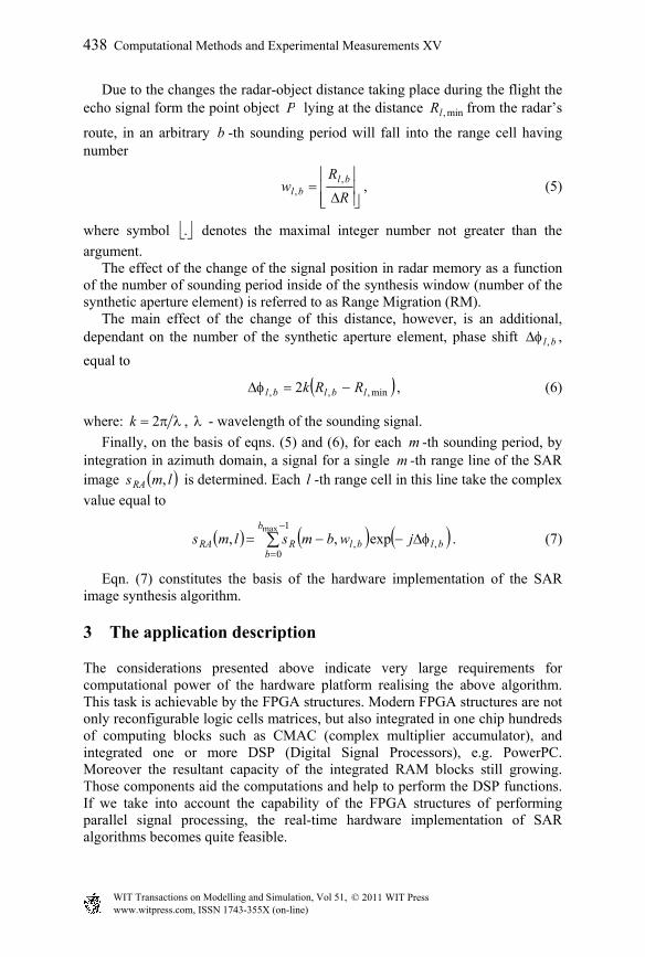
For the considerations as well as for the practical implementation an assumption of strip-map mode of the SAR sensor was made. The geometry of the system during the observation of a single point object is presented in fig. 1.
dm-(bmax-1) m-b m m+1
Rl,min
Rmin
Rmin
Rl,b
lR wl,bR
P
Figure 1: Side-looking SAR in stripmap mode with single point target.
436 Computational Methods and Experimental Measurements XV
www.witpress.com, ISSN 1743-355X (on-line) WIT Transactions on Modelling and Simulation, Vol 51, © 2011 WIT Press
The radars carrier (a plane or a UAV) is moving with a constant velocity along a straight line at a constant height H. The distance d between the two consecutive radar positions in which the radar emits the sounding impulses with the pulse repetition frequency PRF is given by
PRF
d
. (1)
The raw SAR signal ts received in consecutive observations is sampled and
denoted as a series of samples ls , where l - is a number of a sample. The size
of the range cell R , resulting from the sampling operation is equal to
s
s
f
cctR
22 , (2)
where: c - speed of light, st - sampling time interval and sf - sampling
frequency. A the first stage of raw SAR signal processing the matched filtration in range is performed, as a result of which we obtain for each m -th sounding and for each l -th range cell discrete signal lmsR , . As a reference signal for the matched
filtration in range the sounding impulse replica is used. The second and the main stage of SAR signal processing is matched filtration in azimuth, implemented in time domain. This operation is also called SAR image synthesis. It is performed in a synthesis window having azimuthal size equal to maxb , expressed in the number of sounding periods. The size of the
synthesis window is also the length of the synthetic aperture. For each m -th sounding period the length of synthesis window is defined in the limits from
1max bm to m the sounding.
The nature of the pulsed radar assumes some minimal range of reception
min .R
For an exemplary point object P (fig. 1), laying in the l -th range cell the minimal distance radar - object min,lR can be defined as
RlRRl minmin, . (3)
The distance between the radar and the point object in an arbitrary b -th sounding period inside the synthesis window is equal to
2
max2min,, 2
1
db
bRR lbl . (4)
Computational Methods and Experimental Measurements XV 437
www.witpress.com, ISSN 1743-355X (on-line) WIT Transactions on Modelling and Simulation, Vol 51, © 2011 WIT Press
Due to the changes the radar-object distance taking place during the flight the echo signal form the point object P lying at the distance min,lR from the radar’s
route, in an arbitrary b -th sounding period will fall into the range cell having number
R
Rw
blbl
,, , (5)
where symbol . denotes the maximal integer number not greater than the
argument. The effect of the change of the signal position in radar memory as a function of the number of sounding period inside of the synthesis window (number of the synthetic aperture element) is referred to as Range Migration (RM). The main effect of the change of this distance, however, is an additional, dependant on the number of the synthetic aperture element, phase shift bl , ,
equal to
min,,, 2 lblbl RRk , (6)
where: 2k , - wavelength of the sounding signal.
Finally, on the basis of eqns. (5) and (6), for each m -th sounding period, by integration in azimuth domain, a signal for a single m -th range line of the SAR image lmsRA , is determined. Each l -th range cell in this line take the complex
value equal to
1
0,,
maxexp,,
b
bblblRRA jwbmslms . (7)
Eqn. (7) constitutes the basis of the hardware implementation of the SAR image synthesis algorithm.
3 The application description
The considerations presented above indicate very large requirements for computational power of the hardware platform realising the above algorithm. This task is achievable by the FPGA structures. Modern FPGA structures are not only reconfigurable logic cells matrices, but also integrated in one chip hundreds of computing blocks such as CMAC (complex multiplier accumulator), and integrated one or more DSP (Digital Signal Processors), e.g. PowerPC. Moreover the resultant capacity of the integrated RAM blocks still growing. Those components aid the computations and help to perform the DSP functions. If we take into account the capability of the FPGA structures of performing parallel signal processing, the real-time hardware implementation of SAR algorithms becomes quite feasible.
438 Computational Methods and Experimental Measurements XV
www.witpress.com, ISSN 1743-355X (on-line) WIT Transactions on Modelling and Simulation, Vol 51, © 2011 WIT Press
Due to the experimental nature of the project, the decision was made on the purchase of the COTS (Commercial Off-The-Shelf) FPGA modules and the dedicated software enabling development of a specialised signal processing system with the use of PC. Hardware platform was build on the basis of Sundance DSP/FPGA functional modules utilising Xilinx FPGA Virtex-5 SX95T chips and Texas Instruments C6455 DSP. The following module types were used:
1. SMT362 – 1 piece; DSP/FPGA module containing 2 C6455 digital signal processors and Virtex-4 FX FPGA,
2. SMT351T – 2 pieces.; a module containing Virtex-5 SX95T FPGA and (external to FPGA chip) 2 GB of DDR2SDRAM memory.
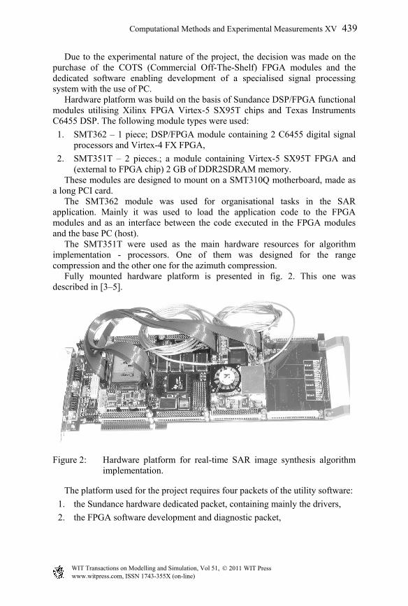
These modules are designed to mount on a SMT310Q motherboard, made as a long PCI card. The SMT362 module was used for organisational tasks in the SAR application. Mainly it was used to load the application code to the FPGA modules and as an interface between the code executed in the FPGA modules and the base PC (host). The SMT351T were used as the main hardware resources for algorithm implementation - processors. One of them was designed for the range compression and the other one for the azimuth compression. Fully mounted hardware platform is presented in fig. 2. This one was described in [3–5].
Figure 2: Hardware platform for real-time SAR image synthesis algorithm implementation.
The platform used for the project requires four packets of the utility software:
1. the Sundance hardware dedicated packet, containing mainly the drivers,
2. the FPGA software development and diagnostic packet,
Computational Methods and Experimental Measurements XV 439
www.witpress.com, ISSN 1743-355X (on-line) WIT Transactions on Modelling and Simulation, Vol 51, © 2011 WIT Press
3. the Code Composer Studio packet designed for the development and diagnostic of the DSP C6000 series processors software,
4. the 3L Diamond packet, aiding the development of applications combining the C written software for the DSP and VHDL written software for the FPGA.
4 Research results
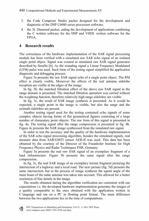
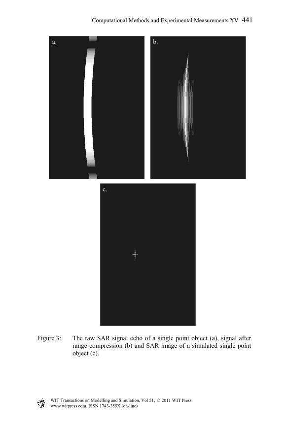
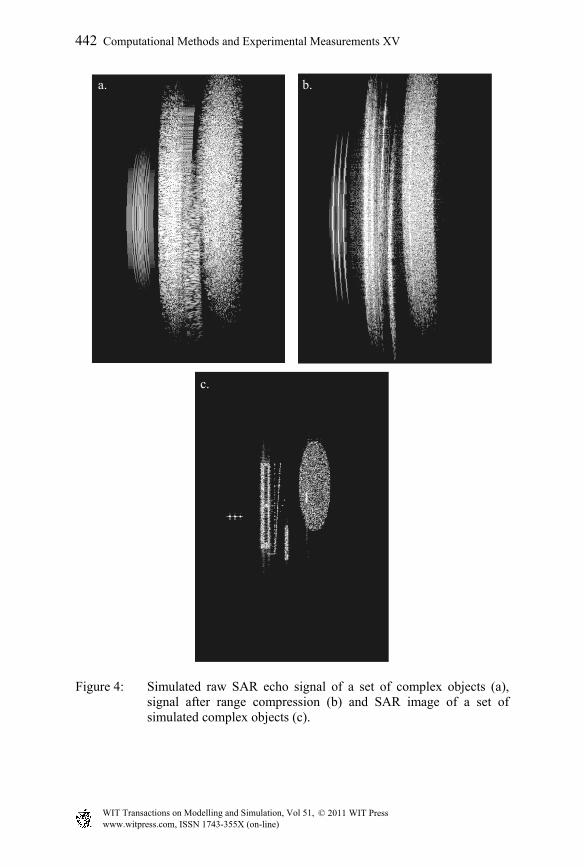
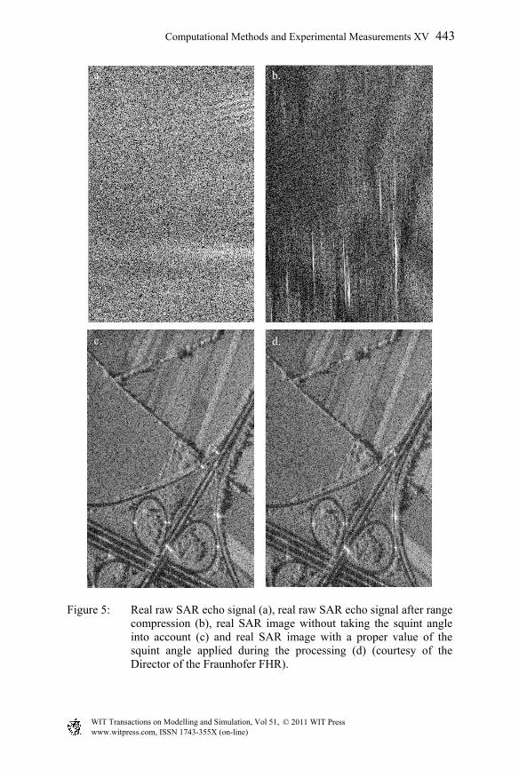
The correctness of the hardware implementation of the SAR signal processing module has been verified with a simulated raw SAR echo signal of an isolated single point object. Signal was created in simulated raw SAR signal generator described by Serafin [6]. As the sounding signal a Linear Frequency Modulated (LFM) pulse was used. Such form of the testing signal simplified the application diagnostic and debugging process. Figure 3a presents the raw SAR signal echo of a single point object. The RM effect is clearly visible. Moreover the effects of the real antenna sidelobe reception are visible at the edges of the image. In fig. 3b, the matched filtration effect of the above raw SAR signal in the range domain is presented. The matched filtration operation was carried without the weighting function, therefore relatively high range sidelobes are visible. In fig. 3c, the result of SAR image synthesis is presented. As it would be expected, a single point in the image is visible, but also the range and the azimuth sidelobes are present. Another testing signal used for the testing contained echo signals of some complex objects having forms of flat geometrical figures consisting of a large number of elementary point objects. The raw form of this signal is presented in fig. 4a. The testing signal after the range compression is presented in fig. 4b. Figure 4c presents the SAR image synthesised from the simulated raw signal. In order to test the accuracy and the quality of the hardware implementation of the SAR echo signal processing algorithm, besides the simulated signals, real measure data from SAR/GMTI sensor AER-II was used. This data has been obtained by the courtesy of the Director of the Fraunhofer Institute for High Frequency Physics and Radar Techniques FHR, Germany. Figure 5a presents the real raw SAR signal of an exemplary fragment of a land infrastructure. Figure 5b presents the same signal after the range compression. In fig. 5c, the real SAR image of an exemplary terrain fragment picturing the intersection of a highway and a local road. The next picture (fig. 5d) presents the same intersection, but in the process of image synthesis the squint angle of the main beam of the radar antenna was taken into account. This allowed for a better resolution of fine details in the image. The results obtained during the algorithm verification are consistent with our expectations i.e. the developed hardware implementation generates the images of a quality comparable to the ones obtained with the application written in C language and ran on a PC in floating point format. The main difference between the two applications lies in the time of computations.
440 Computational Methods and Experimental Measurements XV
www.witpress.com, ISSN 1743-355X (on-line) WIT Transactions on Modelling and Simulation, Vol 51, © 2011 WIT Press
a. b.
c.
Figure 3: The raw SAR signal echo of a single point object (a), signal after range compression (b) and SAR image of a simulated single point object (c).
Computational Methods and Experimental Measurements XV 441
www.witpress.com, ISSN 1743-355X (on-line) WIT Transactions on Modelling and Simulation, Vol 51, © 2011 WIT Press
a. b.
c.
Figure 4: Simulated raw SAR echo signal of a set of complex objects (a), signal after range compression (b) and SAR image of a set of simulated complex objects (c).
442 Computational Methods and Experimental Measurements XV
www.witpress.com, ISSN 1743-355X (on-line) WIT Transactions on Modelling and Simulation, Vol 51, © 2011 WIT Press
a. b.
c. d.
Figure 5: Real raw SAR echo signal (a), real raw SAR echo signal after range compression (b), real SAR image without taking the squint angle into account (c) and real SAR image with a proper value of the squint angle applied during the processing (d) (courtesy of the Director of the Fraunhofer FHR).
Computational Methods and Experimental Measurements XV 443
www.witpress.com, ISSN 1743-355X (on-line) WIT Transactions on Modelling and Simulation, Vol 51, © 2011 WIT Press
5 Conclusions
The hardware implemented in FPGA modules SAR image synthesis algorithm proved to be able to generate SAR image of a width of about 0.5 km in the real time, with the PRF of an order of a few hundreds of Hertz. Those values are acceptable for the SAR sensors mounted onboard UAV’s. We should, however, mention that the implemented algorithm is very computationally demanding, and its current implementation is the first one without any optimisations. Despite very high complexity of the implemented algorithm, the report from the resultant code generation indicates on a relatively low degree of the logical FPGA resources occupied by the application (about 30%), with the exception of the block memory (RAMB) whose usage exceeds 90%. Presented research results of the hardware implementation of the SAR image synthesis module confirmed the feasibility of single FPGA implementation of the algorithm. This leads to creation of compact and low energy consuming applications working in the real time, especially attractive for the UAV applications.
Acknowledgement
This work was supported by the Polish Ministry of Science and Higher Education from sources for science in the years 2009-2011 under project OR00006909.
References
[1] Cumming, I.G. & Wong, F.H., Digital Processing of Synthetic Aperture Radar Data. Algorithms and Implementation, Artech House: London and Boston, 2005.
[2] Wang, Bu-Chin, Digital Signal Processing Techniques and Applications in Radar Image Processing, John Wiley & Sons: Hoboken, USA, 2008.
[3] SMT310Q User Manual, version 2.1, Sundance Multiprocessor Technology Ltd. 2005.
[4] SMT351T User Guide, version 1.0.6, Sundance Multiprocessor Technology Ltd. 2008.
[5] User Manual for SMT362, version 2.2, Sundance Multiprocessor Technology Ltd. 2009.
[6] Serafin, P., Institute of Radioelectronics Technical Report, Warsaw, 2009, (in Polish).
444 Computational Methods and Experimental Measurements XV
www.witpress.com, ISSN 1743-355X (on-line) WIT Transactions on Modelling and Simulation, Vol 51, © 2011 WIT Press