Embed Size (px)
Citation preview
A quick introduction to SpatiaLite Topology
*** D R A F T ***
OGC-SFS GeometriesAs you already know, the standard representation of Geometries supported by any existing Spatial DBMS is based on the following SFS classes (non-topological):
• (MULTI)POINT • (MULTI)LINESTRING • (MULTI)POLYGON • GEOMETRYCOLLECTION
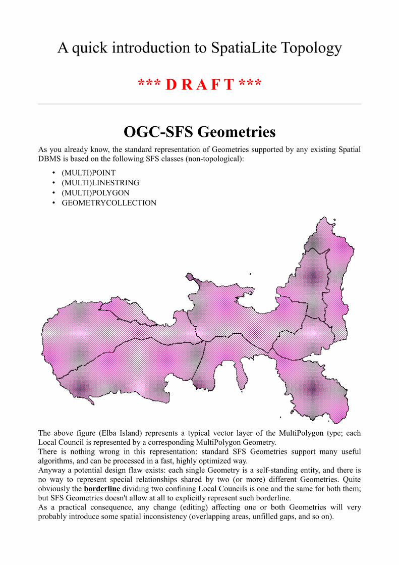
The above figure (Elba Island) represents a typical vector layer of the MultiPolygon type; each Local Council is represented by a corresponding MultiPolygon Geometry.There is nothing wrong in this representation: standard SFS Geometries support many useful algorithms, and can be processed in a fast, highly optimized way.Anyway a potential design flaw exists: each single Geometry is a self-standing entity, and there is no way to represent special relationships shared by two (or more) different Geometries. Quite obviously the borderline dividing two confining Local Councils is one and the same for both them; but SFS Geometries doesn't allow at all to explicitly represent such borderline.As a practical consequence, any change (editing) affecting one or both Geometries will very probably introduce some spatial inconsistency (overlapping areas, unfilled gaps, and so on).
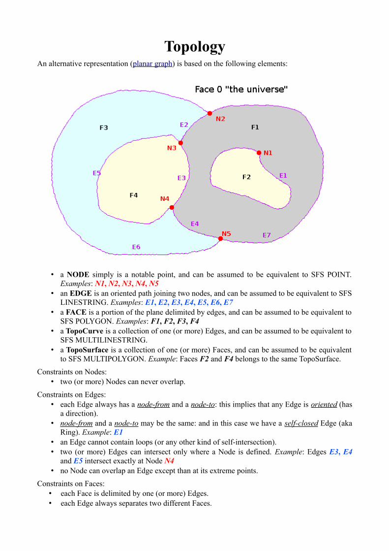
TopologyAn alternative representation (planar graph) is based on the following elements:
• a NODE simply is a notable point, and can be assumed to be equivalent to SFS POINT. Examples: N1, N2, N3, N4, N5
• an EDGE is an oriented path joining two nodes, and can be assumed to be equivalent to SFS LINESTRING. Examples: E1, E2, E3, E4, E5, E6, E7
• a FACE is a portion of the plane delimited by edges, and can be assumed to be equivalent to SFS POLYGON. Examples: F1, F2, F3, F4
• a TopoCurve is a collection of one (or more) Edges, and can be assumed to be equivalent to SFS MULTILINESTRING.
• a TopoSurface is a collection of one (or more) Faces, and can be assumed to be equivalent to SFS MULTIPOLYGON. Example: Faces F2 and F4 belongs to the same TopoSurface.
Constraints on Nodes:• two (or more) Nodes can never overlap.
Constraints on Edges:• each Edge always has a node-from and a node-to: this implies that any Edge is oriented (has
a direction).• node-from and a node-to may be the same: and in this case we have a self-closed Edge (aka
Ring). Example: E1 • an Edge cannot contain loops (or any other kind of self-intersection).• two (or more) Edges can intersect only where a Node is defined. Example: Edges E3, E4
and E5 intersect exactly at Node N4 • no Node can overlap an Edge except than at its extreme points.
Constraints on Faces:• each Face is delimited by one (or more) Edges.• each Edge always separates two different Faces.
The Universe: Face 0• a fictitious Face 0 (aka “The Universe”) is silently assumed to exist; Face 0 covers the
whole plane where no other Face is explicitly defined.• as a consequence, any Edge surely always divides two different Faces:
◦ e.g. the Edge E3 separates the Faces F1 and F4◦ whilst Edge E6 separates Face F3 and the universal Face 0.
Representation of Faces:• as already stated, each Face is delimited by a set of Edges: Example: Face F3 is delimited by
Edges E2, E5, E4 and E6 • a Face can be delimited by a single Edge: Example: Face F2 is delimited by Edge E1 • a Face must always have an exterior boundary; but can legitimately have one (or more)
interior boundaries (aka holes) at the same time. Example: Face F1 is delimited by Edges E1, E2, E3 and E7
• Edges E2, E3 and E7 represent the exterior boundary • Edge E1 represents an interior boundary (i.e. a hole).
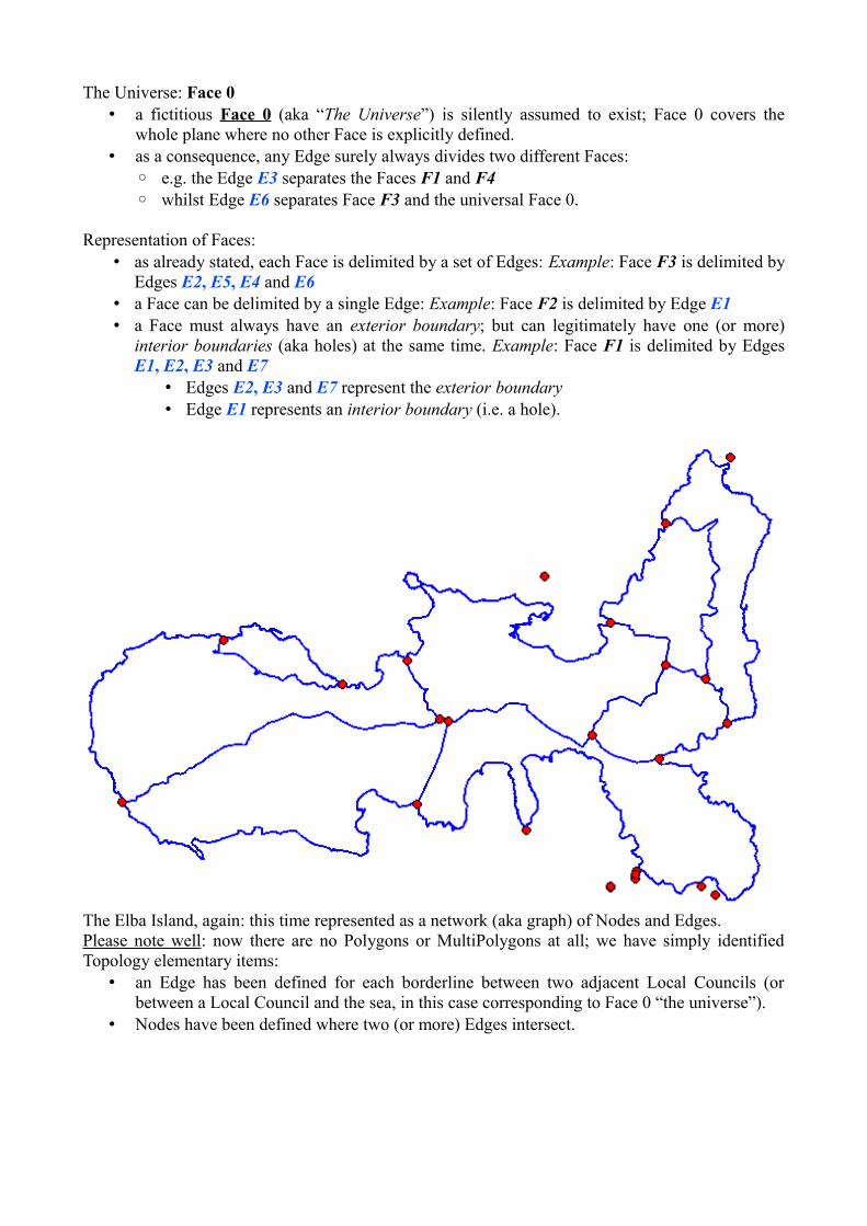
The Elba Island, again: this time represented as a network (aka graph) of Nodes and Edges. Please note well: now there are no Polygons or MultiPolygons at all; we have simply identified Topology elementary items:
• an Edge has been defined for each borderline between two adjacent Local Councils (or between a Local Council and the sea, in this case corresponding to Face 0 “the universe”).
• Nodes have been defined where two (or more) Edges intersect.
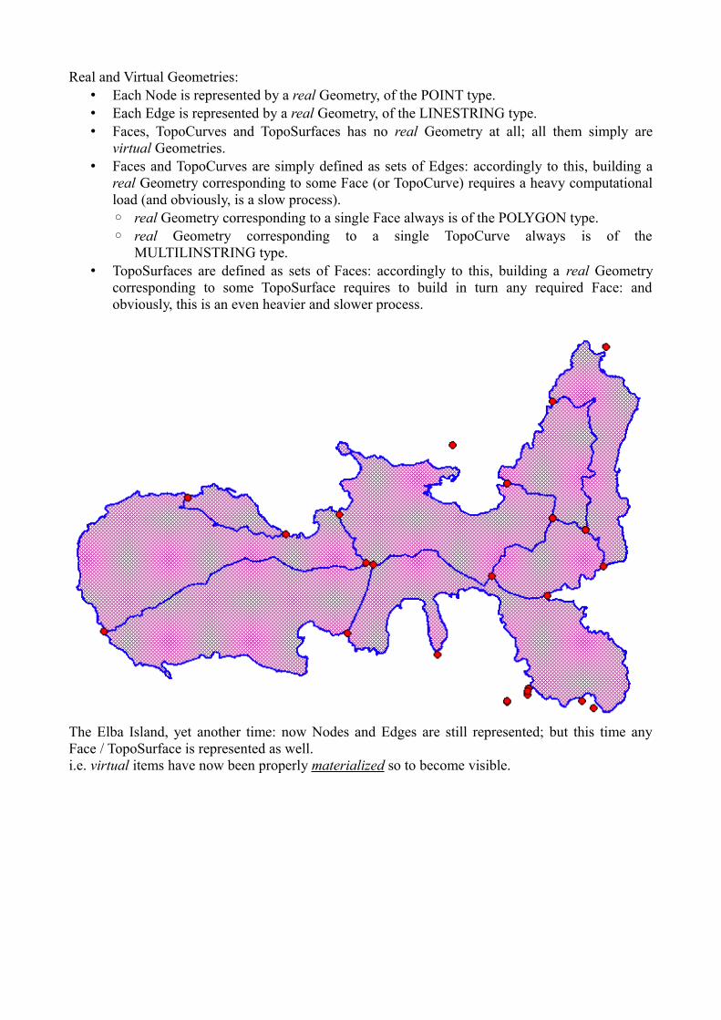
Real and Virtual Geometries:• Each Node is represented by a real Geometry, of the POINT type.• Each Edge is represented by a real Geometry, of the LINESTRING type.• Faces, TopoCurves and TopoSurfaces has no real Geometry at all; all them simply are
virtual Geometries.• Faces and TopoCurves are simply defined as sets of Edges: accordingly to this, building a
real Geometry corresponding to some Face (or TopoCurve) requires a heavy computational load (and obviously, is a slow process).◦ real Geometry corresponding to a single Face always is of the POLYGON type.◦ real Geometry corresponding to a single TopoCurve always is of the
MULTILINSTRING type.• TopoSurfaces are defined as sets of Faces: accordingly to this, building a real Geometry
corresponding to some TopoSurface requires to build in turn any required Face: and obviously, this is an even heavier and slower process.
The Elba Island, yet another time: now Nodes and Edges are still represented; but this time any Face / TopoSurface is represented as well.i.e. virtual items have now been properly materialized so to become visible.
Pros and Cons in using Topology:• Pros :
◦ any special spatial relationship is clearly and unambiguously defined. ◦ Editing/modifying the borderline between two different Local Councils now requires
editing the corresponding Edge (and, may be, some Node). ◦ such change will surely affect both Local Councils at the same time, thus preserving a
strong spatial consistency.• Cons:
◦ high-level objects (Faces, TopoCurves and TopoSurfaces) simply are virtual.◦ materializing the real representation for virtual objects is a heavy (and slow) task. ◦ very few GIS tools support Topological editing; notably, not the most widely used ones.
Topology support implemented in SpatiaLite 3.0.xSpatiaLite is an unsophisticated, easy to be used and light-weight Spatial DBMS mainly intended for personal (Desktop) usage.So don't expect too much, a complete and comprehensive implementation of Topology is not yet available (at least, not for the current release … may well be in the future, who knows).
The initial goals of this first Topology support are not at all too much ambitious, and are simply limited to support the following very basic tasks:
• storing a full Topology (based on Nodes, Edges, Faces, TopoCurves and TopoSurfaces) within a DB-file
• supporting a minimal set of validation tools useful to check for sanity and consistency.• reconstructing classic SFS Geometries (MULTILINESTRINGs and MULTIPOLYGONs)
starting from their corresponding topological representations.
A practical tutorialYou can download a SpatiaLite DB containing a full Topology sample (Local Councils of Italy) from this URL: http://www.gaia-gis.it/gaia-sins/italy-topo.7z This DB is compressed (7-Zip) and has a size of about 15.5 MB: once you've downloaded (and uncompressed) the DB-file you can directly open it using the latest spatialite_gui-1.5.0
Copyright disclaimer:the original dataset [Italian Local Councils Administrative Boundaries] is produced by ISTAT [Italian Census Agency] and is kindly released under a CC-BY open data license. The DB itself containing rearranged data is released under CC-BY terms as well.Author: Alessandro Furieri (2012)
http://creativecommons.org/licenses/by/3.0/deed.en
As you can immediately notice, this DB doesn't contains any Geometry Table at all: don't be fooled by this quick first glance; this one actually is a Spatial DBMS, after all.
Let us go to explore in further depth the general DB layout, table by table and view by view ...
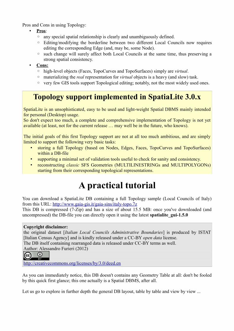
regionsa plain Table, simply containing ids and names for Italy's Regions; not very interesting.
countiesyet another plain Table representing Italy's Counties; not at all exciting.This time we have a Foreign Key referencing regions, but there isn't the slightest trace of Geometry.
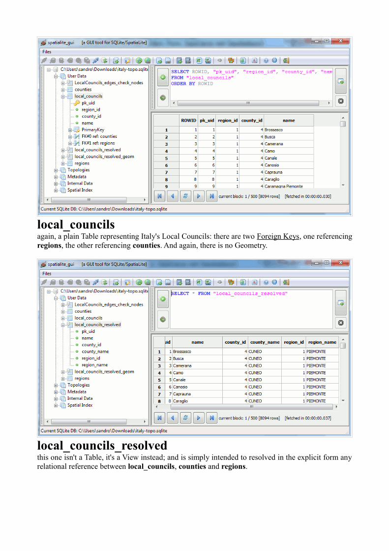
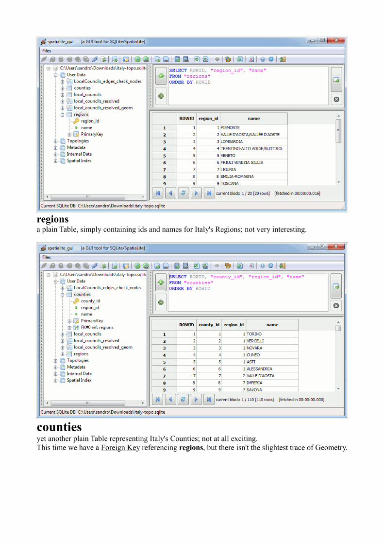
local_councilsagain, a plain Table representing Italy's Local Councils: there are two Foreign Keys, one referencing regions, the other referencing counties. And again, there is no Geometry.
local_councils_resolvedthis one isn't a Table, it's a View instead; and is simply intended to resolved in the explicit form any relational reference between local_councils, counties and regions.
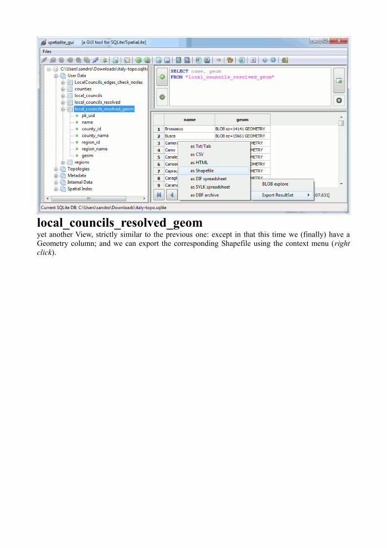
local_councils_resolved_geomyet another View, strictly similar to the previous one: except in that this time we (finally) have a Geometry column; and we can export the corresponding Shapefile using the context menu (right click).
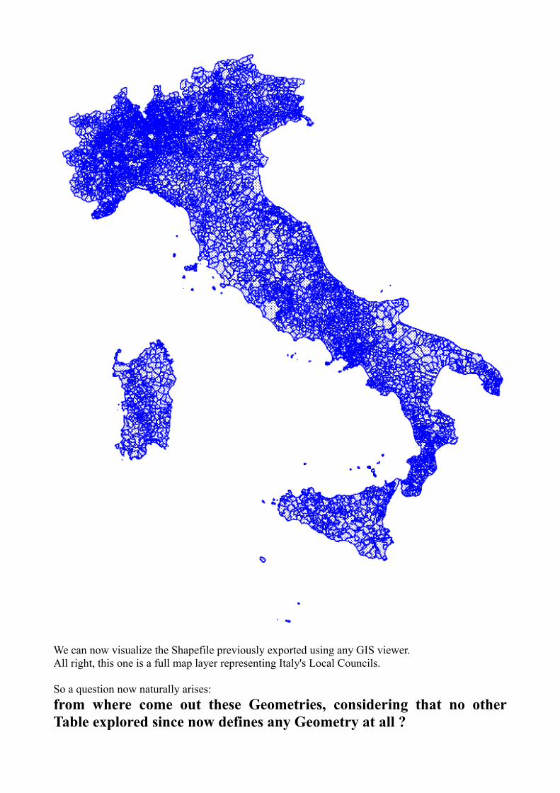
We can now visualize the Shapefile previously exported using any GIS viewer.All right, this one is a full map layer representing Italy's Local Councils.
So a question now naturally arises: from where come out these Geometries, considering that no other Table explored since now defines any Geometry at all ?
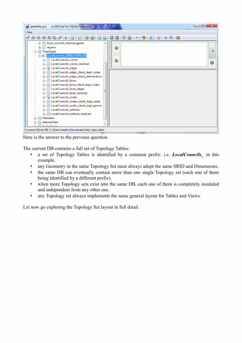
Here is the answer to the previous question.
The current DB contains a full set of Topology Tables:• a set of Topology Tables is identified by a common prefix: i.e. LocalCouncils_ in this
example.• any Geometry in the same Topology Set must always adopt the same SRID and Dimensions.• the same DB can eventually contain more than one single Topology set (each one of them
being identified by a different prefix). • when more Topology sets exist into the same DB, each one of them is completely insulated
and independent from any other one.• any Topology set always implements the same general layout for Tables and Views.
Let now go exploring the Topology Set layout in full detail.
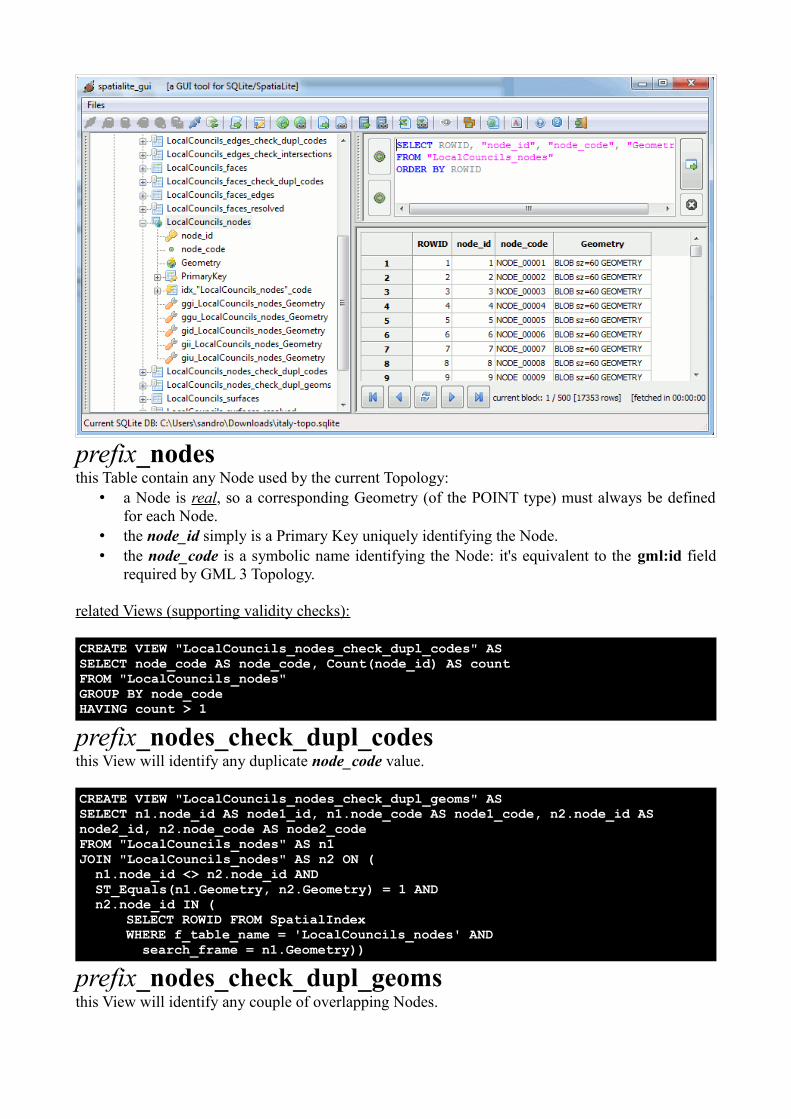
prefix_nodesthis Table contain any Node used by the current Topology:
• a Node is real, so a corresponding Geometry (of the POINT type) must always be defined for each Node.
• the node_id simply is a Primary Key uniquely identifying the Node.• the node_code is a symbolic name identifying the Node: it's equivalent to the gml:id field
required by GML 3 Topology.
related Views (supporting validity checks):
CREATE VIEW "LocalCouncils_nodes_check_dupl_codes" ASSELECT node_code AS node_code, Count(node_id) AS countFROM "LocalCouncils_nodes"GROUP BY node_codeHAVING count > 1
prefix_nodes_check_dupl_codesthis View will identify any duplicate node_code value.
CREATE VIEW "LocalCouncils_nodes_check_dupl_geoms" ASSELECT n1.node_id AS node1_id, n1.node_code AS node1_code, n2.node_id AS node2_id, n2.node_code AS node2_codeFROM "LocalCouncils_nodes" AS n1JOIN "LocalCouncils_nodes" AS n2 ON ( n1.node_id <> n2.node_id AND ST_Equals(n1.Geometry, n2.Geometry) = 1 AND n2.node_id IN (
SELECT ROWID FROM SpatialIndexWHERE f_table_name = 'LocalCouncils_nodes' AND search_frame = n1.Geometry))
prefix_nodes_check_dupl_geomsthis View will identify any couple of overlapping Nodes.
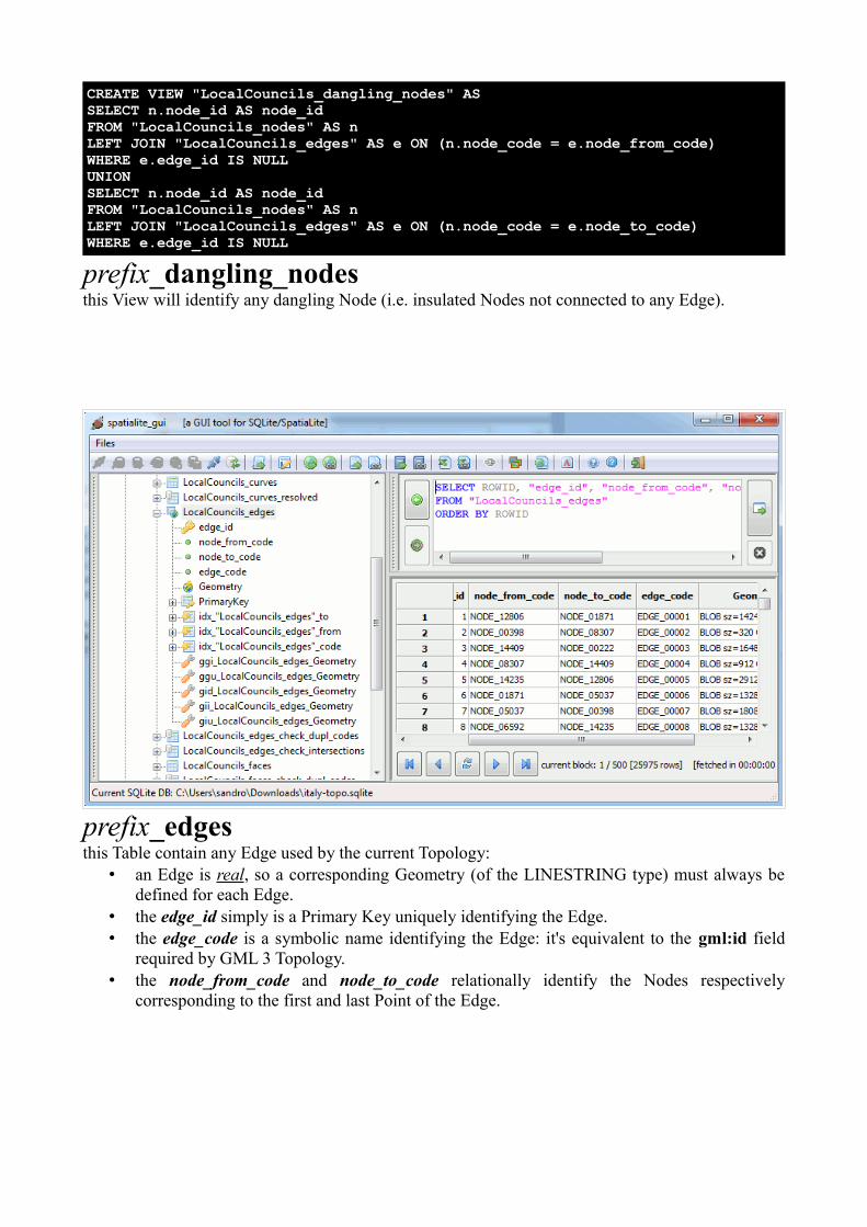
CREATE VIEW "LocalCouncils_dangling_nodes" ASSELECT n.node_id AS node_idFROM "LocalCouncils_nodes" AS nLEFT JOIN "LocalCouncils_edges" AS e ON (n.node_code = e.node_from_code)WHERE e.edge_id IS NULLUNIONSELECT n.node_id AS node_idFROM "LocalCouncils_nodes" AS nLEFT JOIN "LocalCouncils_edges" AS e ON (n.node_code = e.node_to_code)WHERE e.edge_id IS NULL
prefix_dangling_nodesthis View will identify any dangling Node (i.e. insulated Nodes not connected to any Edge).
prefix_edgesthis Table contain any Edge used by the current Topology:
• an Edge is real, so a corresponding Geometry (of the LINESTRING type) must always be defined for each Edge.
• the edge_id simply is a Primary Key uniquely identifying the Edge.• the edge_code is a symbolic name identifying the Edge: it's equivalent to the gml:id field
required by GML 3 Topology.• the node_from_code and node_to_code relationally identify the Nodes respectively
corresponding to the first and last Point of the Edge.
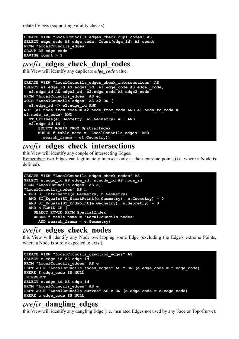
related Views (supporting validity checks):
CREATE VIEW "LocalCouncils_edges_check_dupl_codes" ASSELECT edge_code AS edge_code, Count(edge_id) AS countFROM "LocalCouncils_edges"GROUP BY edge_codeHAVING count > 1
prefix_edges_check_dupl_codesthis View will identify any duplicate edge_code value.
CREATE VIEW "LocalCouncils_edges_check_intersections" ASSELECT e1.edge_id AS edge1_id, e1.edge_code AS edge1_code, e2.edge_id AS edge2_id, e2.edge_code AS edge2_codeFROM "LocalCouncils_edges" AS e1JOIN "LocalCouncils_edges" AS e2 ON ( e1.edge_id <> e2.edge_id ANDNOT (e1.node_from_code = e2.node_from_code AND e1.node_to_code = e2.node_to_code) AND ST_Crosses(e1.Geometry, e2.Geometry) = 1 AND e2.edge_id IN (
SELECT ROWID FROM SpatialIndexWHERE f_table_name = 'LocalCouncils_edges' AND search_frame = e1.Geometry))
prefix_edges_check_intersectionsthis View will identify any couple of intersecting Edges.Remember: two Edges can legitimately intersect only at their extreme points (i.e. where a Node is defined).
CREATE VIEW "LocalCouncils_edges_check_nodes" ASSELECT e.edge_id AS edge_id, n.node_id AS node_idFROM "LocalCouncils_edges" AS e, "LocalCouncils_nodes" AS nWHERE ST_Intersects(e.Geometry, n.Geometry) AND ST_Equals(ST_StartPoint(e.Geometry), n.Geometry) = 0 AND ST_Equals(ST_EndPoint(e.Geometry), n.Geometry) = 0 AND n.ROWID IN ( SELECT ROWID FROM SpatialIndex WHERE f_table_name = 'LocalCouncils_nodes' AND search_frame = e.Geometry)
prefix_edges_check_nodesthis View will identify any Node overlapping some Edge (excluding the Edge's extreme Points, where a Node is surely expected to exist).
CREATE VIEW "LocalCouncils_dangling_edges" ASSELECT e.edge_id AS edge_idFROM "LocalCouncils_edges" AS eLEFT JOIN "LocalCouncils_faces_edges" AS f ON (e.edge_code = f.edge_code)WHERE f.edge_code IS NULLINTERSECTSELECT e.edge_id AS edge_idFROM "LocalCouncils_edges" AS eLEFT JOIN "LocalCouncils_curves" AS c ON (e.edge_code = c.edge_code)WHERE c.edge_code IS NULL
prefix_dangling_edgesthis View will identify any dangling Edge (i.e. insulated Edges not used by any Face or TopoCurve).
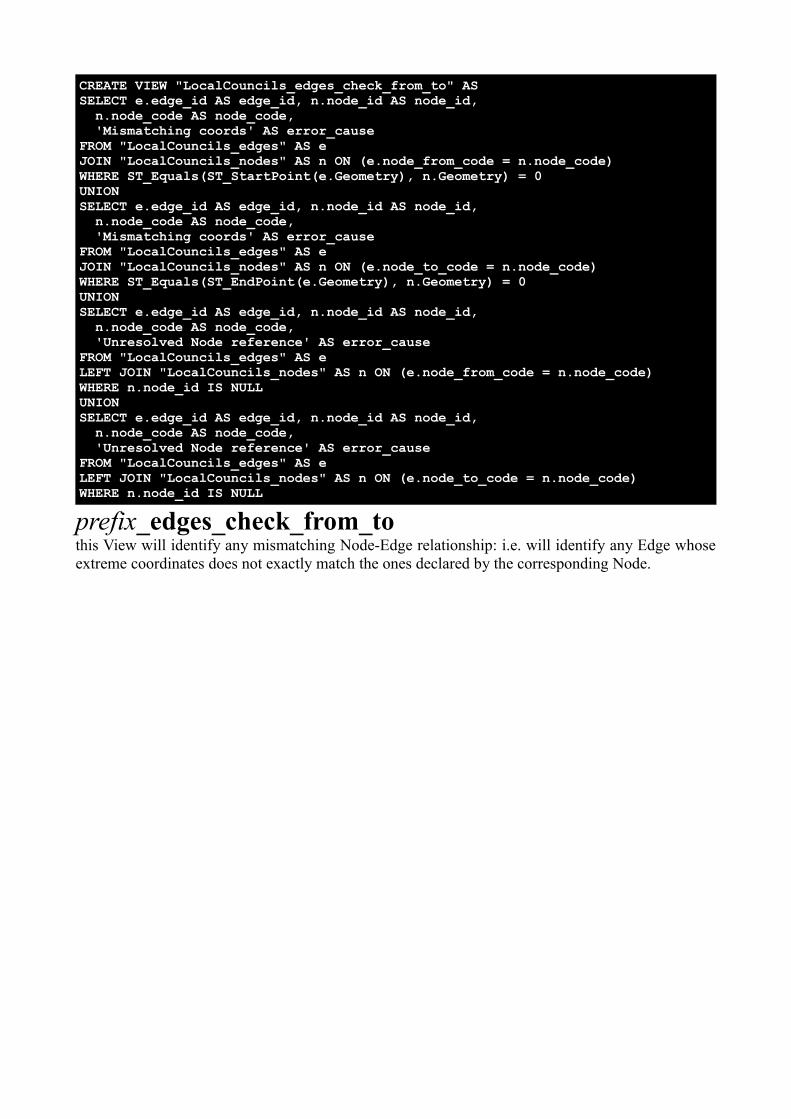
CREATE VIEW "LocalCouncils_edges_check_from_to" ASSELECT e.edge_id AS edge_id, n.node_id AS node_id, n.node_code AS node_code, 'Mismatching coords' AS error_causeFROM "LocalCouncils_edges" AS eJOIN "LocalCouncils_nodes" AS n ON (e.node_from_code = n.node_code)WHERE ST_Equals(ST_StartPoint(e.Geometry), n.Geometry) = 0UNIONSELECT e.edge_id AS edge_id, n.node_id AS node_id, n.node_code AS node_code, 'Mismatching coords' AS error_causeFROM "LocalCouncils_edges" AS eJOIN "LocalCouncils_nodes" AS n ON (e.node_to_code = n.node_code)WHERE ST_Equals(ST_EndPoint(e.Geometry), n.Geometry) = 0UNIONSELECT e.edge_id AS edge_id, n.node_id AS node_id, n.node_code AS node_code, 'Unresolved Node reference' AS error_causeFROM "LocalCouncils_edges" AS eLEFT JOIN "LocalCouncils_nodes" AS n ON (e.node_from_code = n.node_code)WHERE n.node_id IS NULLUNIONSELECT e.edge_id AS edge_id, n.node_id AS node_id, n.node_code AS node_code, 'Unresolved Node reference' AS error_causeFROM "LocalCouncils_edges" AS eLEFT JOIN "LocalCouncils_nodes" AS n ON (e.node_to_code = n.node_code)WHERE n.node_id IS NULL
prefix_edges_check_from_tothis View will identify any mismatching Node-Edge relationship: i.e. will identify any Edge whose extreme coordinates does not exactly match the ones declared by the corresponding Node.
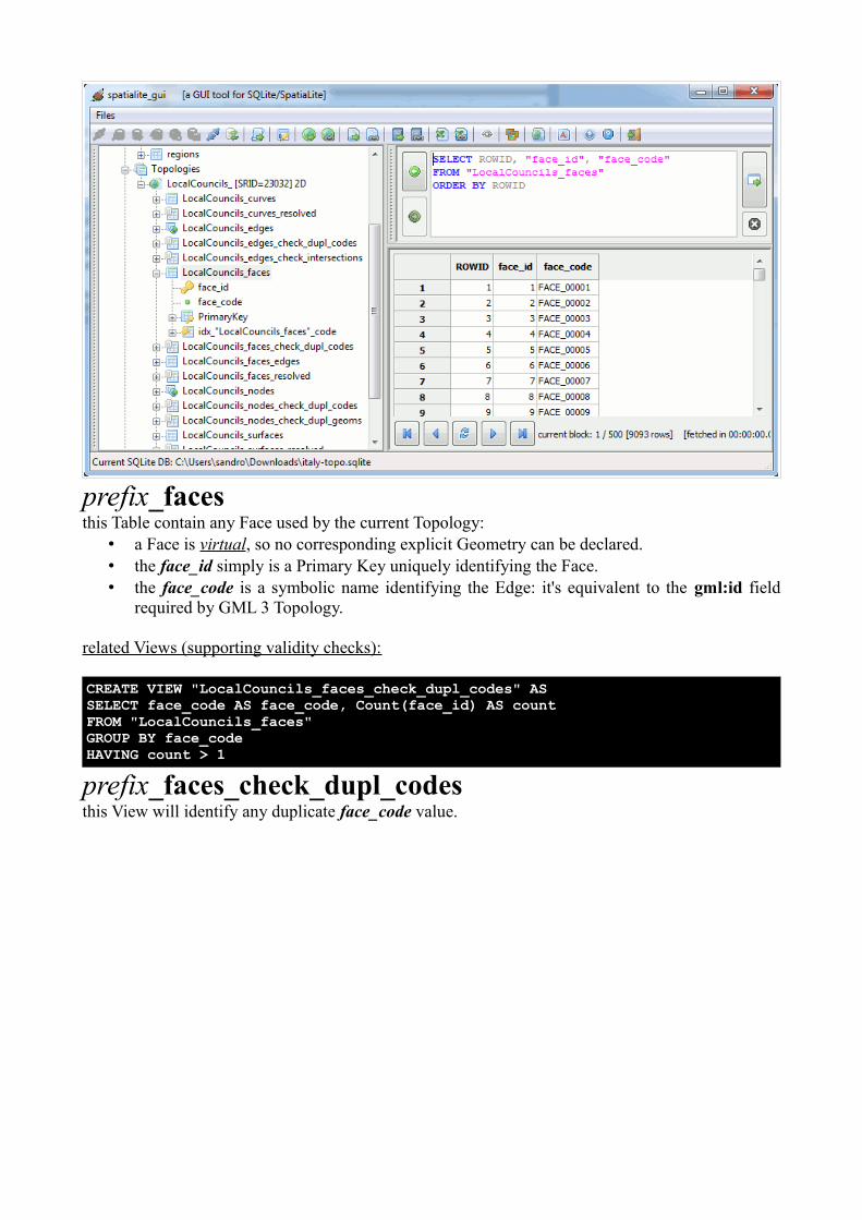
prefix_facesthis Table contain any Face used by the current Topology:
• a Face is virtual, so no corresponding explicit Geometry can be declared.• the face_id simply is a Primary Key uniquely identifying the Face.• the face_code is a symbolic name identifying the Edge: it's equivalent to the gml:id field
required by GML 3 Topology.
related Views (supporting validity checks):
CREATE VIEW "LocalCouncils_faces_check_dupl_codes" ASSELECT face_code AS face_code, Count(face_id) AS countFROM "LocalCouncils_faces"GROUP BY face_codeHAVING count > 1
prefix_faces_check_dupl_codesthis View will identify any duplicate face_code value.
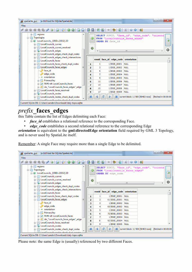
prefix_faces_edgesthis Table contain the list of Edges delimiting each Face:
• face_id establishes a relational reference to the corresponding Face.• edge_code establishes a second relational reference to the corresponding Edge
orientation is equivalent to the gml:directedEdge orientation field required by GML 3 Topology, and is never used by SpatiaLite itself.
Remember: A single Face may require more than a single Edge to be delimited.
Please note: the same Edge is (usually) referenced by two different Faces.
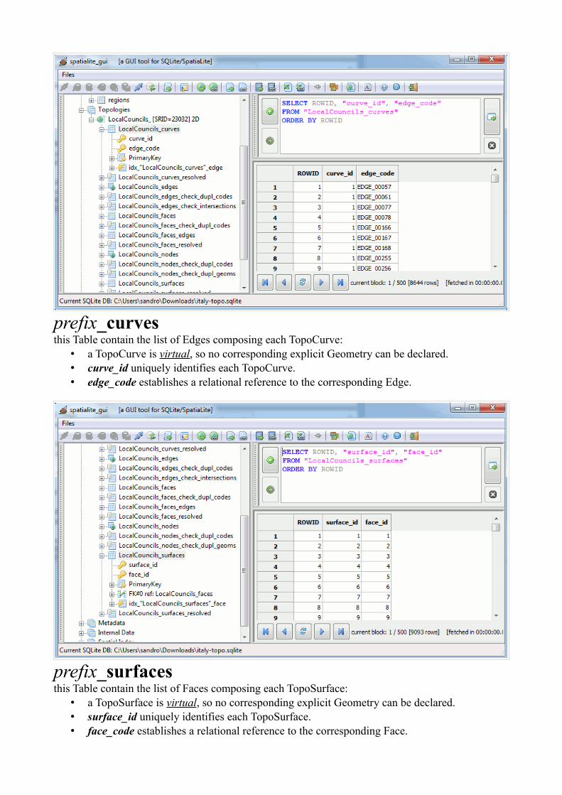
prefix_curvesthis Table contain the list of Edges composing each TopoCurve:
• a TopoCurve is virtual, so no corresponding explicit Geometry can be declared.• curve_id uniquely identifies each TopoCurve.• edge_code establishes a relational reference to the corresponding Edge.
prefix_surfacesthis Table contain the list of Faces composing each TopoSurface:
• a TopoSurface is virtual, so no corresponding explicit Geometry can be declared.• surface_id uniquely identifies each TopoSurface.• face_code establishes a relational reference to the corresponding Face.
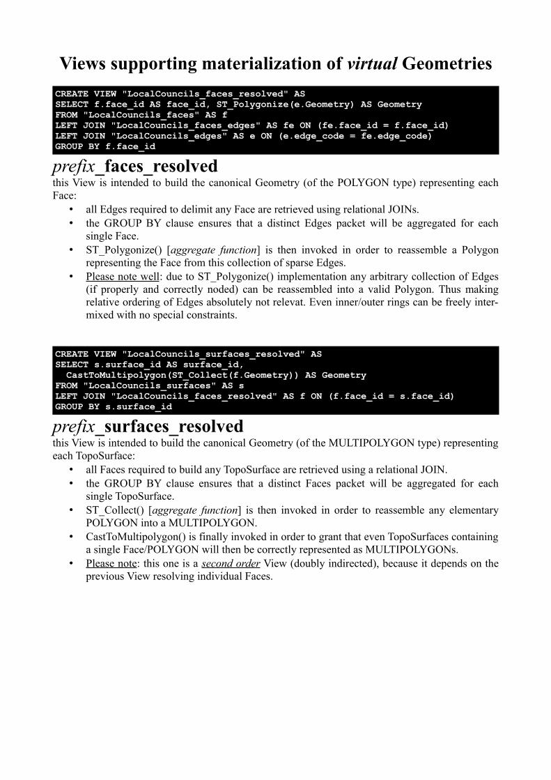
Views supporting materialization of virtual GeometriesCREATE VIEW "LocalCouncils_faces_resolved" ASSELECT f.face_id AS face_id, ST_Polygonize(e.Geometry) AS GeometryFROM "LocalCouncils_faces" AS fLEFT JOIN "LocalCouncils_faces_edges" AS fe ON (fe.face_id = f.face_id)LEFT JOIN "LocalCouncils_edges" AS e ON (e.edge_code = fe.edge_code)GROUP BY f.face_id
prefix_faces_resolvedthis View is intended to build the canonical Geometry (of the POLYGON type) representing each Face:
• all Edges required to delimit any Face are retrieved using relational JOINs.• the GROUP BY clause ensures that a distinct Edges packet will be aggregated for each
single Face.• ST_Polygonize() [aggregate function] is then invoked in order to reassemble a Polygon
representing the Face from this collection of sparse Edges.• Please note well : due to ST_Polygonize() implementation any arbitrary collection of Edges
(if properly and correctly noded) can be reassembled into a valid Polygon. Thus making relative ordering of Edges absolutely not relevat. Even inner/outer rings can be freely inter-mixed with no special constraints.
CREATE VIEW "LocalCouncils_surfaces_resolved" ASSELECT s.surface_id AS surface_id, CastToMultipolygon(ST_Collect(f.Geometry)) AS GeometryFROM "LocalCouncils_surfaces" AS sLEFT JOIN "LocalCouncils_faces_resolved" AS f ON (f.face_id = s.face_id)GROUP BY s.surface_id
prefix_surfaces_resolvedthis View is intended to build the canonical Geometry (of the MULTIPOLYGON type) representing each TopoSurface:
• all Faces required to build any TopoSurface are retrieved using a relational JOIN.• the GROUP BY clause ensures that a distinct Faces packet will be aggregated for each
single TopoSurface.• ST_Collect() [aggregate function] is then invoked in order to reassemble any elementary
POLYGON into a MULTIPOLYGON.• CastToMultipolygon() is finally invoked in order to grant that even TopoSurfaces containing
a single Face/POLYGON will then be correctly represented as MULTIPOLYGONs.• Please note : this one is a second order View (doubly indirected), because it depends on the
previous View resolving individual Faces.
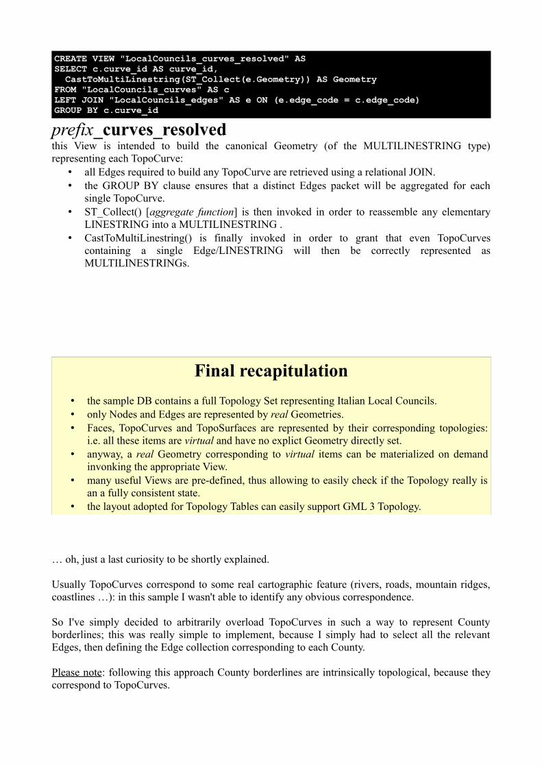
CREATE VIEW "LocalCouncils_curves_resolved" ASSELECT c.curve_id AS curve_id, CastToMultiLinestring(ST_Collect(e.Geometry)) AS GeometryFROM "LocalCouncils_curves" AS cLEFT JOIN "LocalCouncils_edges" AS e ON (e.edge_code = c.edge_code)GROUP BY c.curve_id
prefix_curves_resolvedthis View is intended to build the canonical Geometry (of the MULTILINESTRING type) representing each TopoCurve:
• all Edges required to build any TopoCurve are retrieved using a relational JOIN.• the GROUP BY clause ensures that a distinct Edges packet will be aggregated for each
single TopoCurve.• ST_Collect() [aggregate function] is then invoked in order to reassemble any elementary
LINESTRING into a MULTILINESTRING .• CastToMultiLinestring() is finally invoked in order to grant that even TopoCurves
containing a single Edge/LINESTRING will then be correctly represented as MULTILINESTRINGs.
Final recapitulation• the sample DB contains a full Topology Set representing Italian Local Councils.• only Nodes and Edges are represented by real Geometries.• Faces, TopoCurves and TopoSurfaces are represented by their corresponding topologies:
i.e. all these items are virtual and have no explict Geometry directly set.• anyway, a real Geometry corresponding to virtual items can be materialized on demand
invonking the appropriate View.• many useful Views are pre-defined, thus allowing to easily check if the Topology really is
an a fully consistent state.• the layout adopted for Topology Tables can easily support GML 3 Topology.
… oh, just a last curiosity to be shortly explained.
Usually TopoCurves correspond to some real cartographic feature (rivers, roads, mountain ridges, coastlines …): in this sample I wasn't able to identify any obvious correspondence.
So I've simply decided to arbitrarily overload TopoCurves in such a way to represent County borderlines; this was really simple to implement, because I simply had to select all the relevant Edges, then defining the Edge collection corresponding to each County.
Please note: following this approach County borderlines are intrinsically topological, because they correspond to TopoCurves.
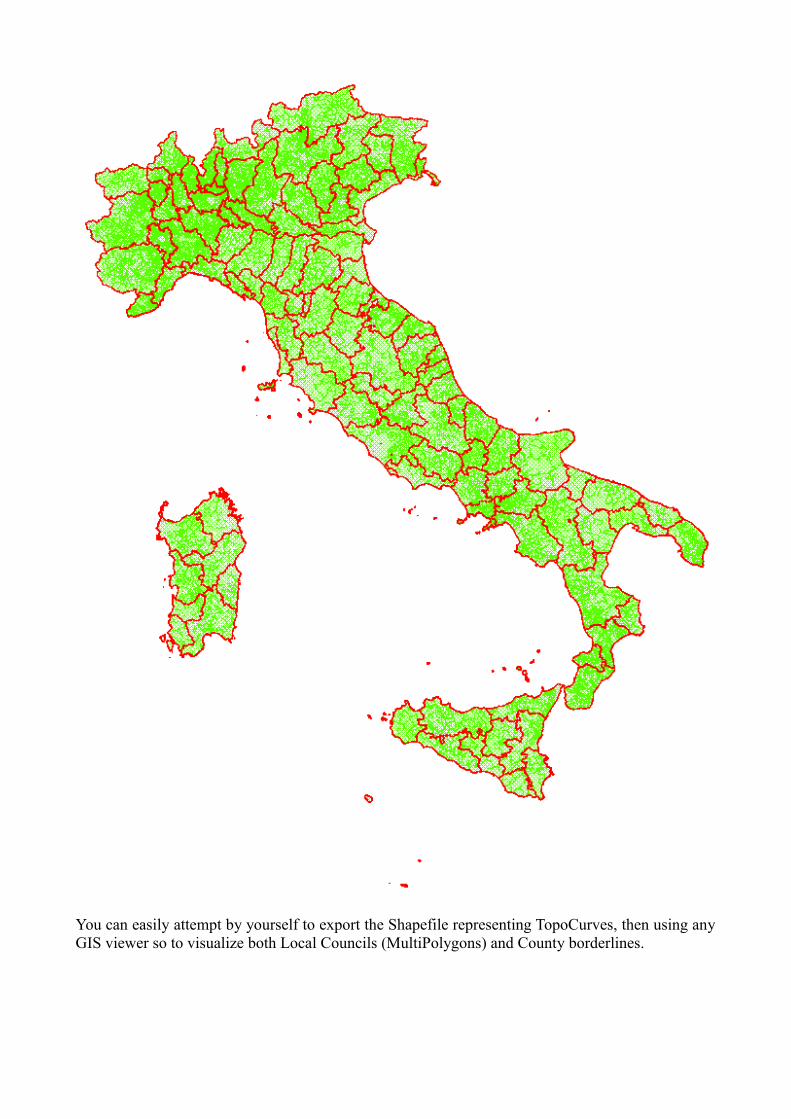
You can easily attempt by yourself to export the Shapefile representing TopoCurves, then using any GIS viewer so to visualize both Local Councils (MultiPolygons) and County borderlines.