Embed Size (px)
Citation preview

A Prototype Silicon Compiler in Prolog04
William BushGino Cheng
Partrick C. McGeerAlvin M. Despain
DTICELECTVJUL 281989
B
Report No. UCB/CSD 88/476
December 1988
Computer Science Division (EECS)University of CaliforniaBerkeley, California 94720
Sfor pubi , 89 7 27 096D• &-t ualwdto
A Prototype Silicon Compiler in Prolog
William R. BushGino Cheng
Patrick C. McGeerAlvin M. Despain
The Advanced Silicon Compiler in Prolog (ASP) is a full-range hardware synthesis sys-tem based on Prolog. It produces VLSI masks from instruction set architecture specificationswritten in Prolog. The system is composed of several hierarchical components that spanbehavioral, circuit, and geometric synthesis. This report describes the prototype ASP systemand its major components.
ACKNOWLEDGEMENT
This research was sponsored by the Defense Advanced Research Projects Agency (DoD), Arpa OrderNo. 6501, and monitored by the Office of Naval Research under Contract No. N00014-88-K-0579.
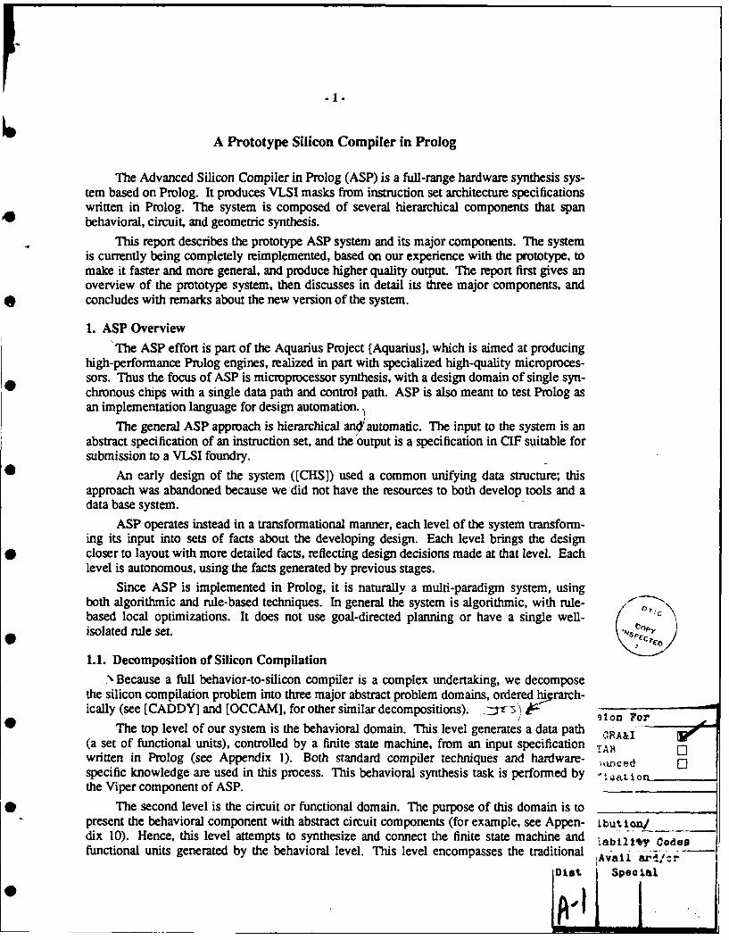
-1-
A Prototype Silicon Compiler in Prolog
The Advanced Silicon Compiler in Prolog (ASP) is a full-range hardware synthesis sys-tem based on Prolog. It produces VLSI masks from instruction set architecture specificationswritten in Prolog. The system is composed of several hierarchical components that spanbehavioral, circuit, and geometric synthesis.
This report describes the prototype ASP system and its major components. The systemis currently being completely reimplemented, based on our experience with the prototype, tomake it faster and more general, and produce higher quality output. The report first gives anoverview of the prototype system, then discusses in detail its three major components, andconcludes with remarks about the new version of the system.
1. ASP Overview
The ASP effort is part of the Aquarius Project [Aquarius], which is aimed at producinghigh-performance Prolog engines, realized in part with specialized high-quality microproces-sors. Thus the focus of ASP is microprocessor synthesis, with a design domain of single syn-chronous chips with a single data path and control path. ASP is also meant to test Prolog asan implementation language for design automation.
The general ASP approach is hierarchical an4'automatic. The input to the system is anabstract specification of an instruction set, and the output is a specification in CIF suitable forsubmission to a VLSI foundry.
An early design of the system ([CHS]) used a common unifying data structure; thisapproach was abandoned because we did not have the resources to both develop tools and adata base system.
ASP operates instead in a transformational manner, each level of the system transform-ing its input into sets of facts about the developing design. Each level brings the designcloser to layout with more detailed facts, reflecting design decisions made at that level. Eachlevel is autonomous, using the facts generated by previous stages.
Since ASP is implemented in Prolog, it is naturally a multi-paradigm system, usingboth algorithmic and rule-based techniques. In general the system is algorithmic, with rule-based local optimizations. It does not use goal-directed planning or have a single well- [ C
isolated rule set.
1.1. Decomposition of Silicon Compilation
:, Because a full behavior-to-silicon compiler is a complex undertaking, we decomposethe silicon compilation problem into three major abstract problem domains, ordered hicrarch-ically (see [CADDY] and [OCCAM], for other similar decompositions). 3 1 on For
The top level of our system is the behavioral domain. This level generates a data path GRA-I(a set of functional units), controlled by a finite state machine, from an input specification TARwritten in Prolog (see Appendix 1). Both standard compiler techniques and hardware- ninced [1specific knowledge are used in this process. This behavioral synthesis task is performed by ua tothe Viper component of ASP.
The second level is the circuit or functional domain. The purpose of this domain is topresent the behavioral component with abstract circuit components (for example, see Appen- tbut on/dix 10). Hence, this level attempts to synthesize and connect the finite state machine and abl odesfunctional units generated by the behavioral level. This level encompasses the traditional Laility Cad -
Dit Spec
0
.2-
tasks of state assignment, logic synthesis, module generation, transistor sizing, placement,and routing. The core of this level is module generation, which is done by the Topolog com-ponent. We also have a CMOS PLA generator and a channel router.
The third level is the geometric domain. The purpose of this domain is to present theprograms of the functional domain with idealized geometric elements, in the form of asticks-and-elements virtual-grid abstraction of actual mask layers (for an example, seeAppendix 13). This domain encompasses the traditional tasks of compaction and device-level simulation. These tasks are accomplished by the Sticks-Pack component of ASP. SeeAppendices 14, 15, and 16 for example layout.
Clearly there is some interaction between the levels. No layout generator can ignore theconstraints inherent in technology, such as, for example, the richer connectivity of two layersof metal compared to a single layer. Similarly, the data path constructor can only use func-tional units that the module generator can generate.
1.2. ViperViper generates structural hardware descriptions from instruction-set level
specifications written in standard Prolog. It performs two basic functions. It translates Pro-log constructs into hardware equivalents, and it creates and allocates hardware resourceswhile satisfying various constraints.
Viper uses a combination of compiler analysis and hardware knowledge. Algorithmiccompiler techniques -- dependency gnalysis, register allocation, and dependency-basedscheduling - are used to produce a basic design with constraints. Hardware specific heuris-tics and knowledge about the characteristics of functional units are then used to generate adesign within the constraints.
Viper operates in four phases: register allocation, translation of the Prolog specificationinto an RTL-based form, data path construction, and structural description generation.
The first phase operates on an input specification written in Prolog and constrained to a 0style illustrated in Appendix 1. First, the microprocessor must be a finite state machine asindicated by the first clause. Second, the model of memory is assumed to be external to themicroprocessor, and is realized in Prolog with assert and retract. The first phase transformsan input specification into an equivalent Prolog program in , 'i'-1 variable references havebeen replaced by assertions involving global data structures tht m dxel registers. As with theoriginal specification, the transformed specification can be execumed directly by a Prolog •interpreter. It also transforms assert and retract into memory references, while providing asystem-defined memory interface.
The second phase converts Prolog goals to register transfers, assigns transfers to FSMstates, and produces a state transition table. The operations appearing in transfers are Prologoperators, such as '+', and are not yet bound to functional unit operations. The schedule oftransfers is maximally parallel, based only on dependencies between values and not onresource constraints.
The third phase produces a constrained data path, mapping abstract operators to func-tional units and minimizing the connections between units. If the system cannot find anavailable functional unit it tries to extend the functionality of an existing one, for example byconverting a register used in an increment expression into a counter (providing enabling con-ditions are met).
40

-3-
Knowledge about functional units is packaged in a library, which also serves as theinterface to lower synthesis levels. Each member of the library contains knowledge, in theform of Prolog assertions, about when and how it should be synthesized. This approach issimilar in spirit to [BUD], but is not object-oriented in implementation. Each library memberalso contains the logic equations and other information necessary for it to be realized as a cir-cuit.
The fourth phase generates a structural description containing a connected data path andcontrol path. Appendix 8 presents the data path derived from the specification in Appendix 1,consisting of named instances of functional unit types along with connected input and outputbuses and control signals. Functional unit implementation is deferred to Topolog. Appendix9 presents the finite state machine control path.
1.3. Topolog
Topolog is the module generator, layout engine, and circuit database manager. It takesin a description of a circuit to be generated, constraints on the bounding box, and a set ofports, and outputs a sticks-based layout description which can be converted to a fabricatableform by the mask-level design environment, Sticks-Pack.
Topolog combines the functions of a module generator and layout engine in an attemptto solve, in combination, problems specific to each. In particular, the availability of a layoutengine permits the module generators to specify a module as a collection of functional blocksrather than pieces of geometry, which significantly simplifies the problem of specifying com-ponents of a module. The module generator is freed from most concerns of geometry, rout-ing and placement, secure that the layout engine will solve the routing and placement prob-lem. Similarly, the collection of circuit elements into modules provides valuable informationto those automated placement tools which either implicitly or explicitly partition a circuitinto connected subcircuits.
Topolog is designed around the basic abstraction of a block. A block represents a prim-itive circuit element. A block has a p-side and an n-side. Topolog's basic function is togroup blocks into rows, and to route signals between the blocks. A single routing channelruns between the p- and n-side of any row; a power bar runs above the p-side of every row,and a ground bar runs beneath the n-side of every row. Odd rows are flipped about the hor-izontal axis so that power and ground bars may be shared between rows. Topolog can bethought of as a standard cell layout program, but since blocks can be anything which has thecharacteristics mentioned here, it is more accurate to describe Topolog as a gate matrix stylelayout engine.
Topolog has a six stage pipeline. After inputs are parsed, a preliminary generation ofall the blocks is done. The blocks are then grouped into rows, and placed within rows. Dur-ing this placement phase, compound blocks are expanded into their primitive componentblocks. Detailed generation of blocks is done; the blocks are fleshed out into a sticks-and-elements description, and the pins for channel routing are defined. The channel is thenrouted. Finally the package is output. An example is shown in Appendix 16, which is a bitslice derived from the data path description in Appendix 8. Our existing logic blocks are alldesigned by the Uehara-Van Cleemput procedure [UVC]. The UVC algorithm has beenshown to derive near-minimal-width single-diffusion-strip static CMOS arrays.
Topolog supports four types of blocks: static CMOS and-or-invert gates, dominoCMOS gates, pass gates and transmission gates. Topolog is designed to support any circuitstyle or technology that can be expressed in the style described above. The terms p-side and

.4-
n-side refer to p- and n-diffusion regions, reflecting our primary concern with CMOS technol-ogy; however, there is no reason, in principle, to use these regions specifically for these pur-poses. One can imagine, for example, using Topolog for NMOS designs using the p-side forthe complementary device. The addition of a new circuit type is easy, due to Prolog'sclause-based programming style. The library routines have so far proved powerful enough tomake the addition of new circuit types almost automatic: the addition of domino CMOSrequired only 30 lines of new Prolog code.
1.4. Sticks-Pack
The Sticks-Pack environment consists of a technology independent compactor thatcreates spaced layout and simulation files from sticks-and-elements descriptions, a joiner thatjoins together cells generated by the compactor, and a simulator that simulates sticks-basedcells.
The Sticks-Pack compactor takes a cell defined in the sticks-and-elements representa-tion used by Topolog (see Appendix 13), and creates a mask level representation for the cell.A new compaction technique is employed which is both algorithmic and rule based. An algo-rithm similar to zone refining is used to perform a rough spacing of the elements. Floor andceiling profiles for each layer of material are maintained. Elements from the ceiling aremoved directly across the molten region to the floor, where spacing requirements are calcu-lated, and diagonal constraints are noted. Rules are used to shift the elements to better fittheir environment. For each cell, a connectivity file containing nodal connectivity, resistivityand capacitance information is generated for the switch-level simulator and for the Spice cir-cuit simulator. The Sticks-Pack compactor is relatively technology independent; it supportsan arbitrary number of layers, and elements such as transistors and contacts are defined froma set of primitives. A design rule file and a set of technology dependent rules are specifiedfor each technology.
Large layouts in Sticks-Pack are realized by joining small cells together. Leaf cells(cells of the lowest level consisting of transistors and wires) are compacted individually andconstitute the building blocks for larger modules. Previous tilers have either pitchmatched orriver routed cells. The joiner program connects signals between cells by either pitchmatchingor river routing, whichever is more area efficient. The joiner operates in the physical domainrather than the virtual grid domain for tighter results. This also allows cells of various virtualgrid heights and widths to be joined.
1.5. Other Components
We have a boolean equation generator that takes the finite state machine descriptionproduced by Viper and does state assignment and generates the equations used by our CMOSPLA generator (see Appendix 11), which then creates AND-OR sticks-and-elements PLAsfrom those boolean equations.
We have a left-edge-first channel router for connecting the major blocks of the system,primarily the data path and control path.
In an effort to improve the performance of our designs, we have investigated transistorsizing with a Prolog-based transistor sizer named Most [Most], which runs standalone.
1.6. The Use of Prolog
The use of Prolog for both specification and implementation arose from experienceusing and implementing Prolog in both a compiler and a new execution engine. Our
-5-
experience with Prolog in ASP has in general been positive.
1.6.1. The Use of Prolog for Implementation
We have observed several benefits in using Prolog for implementation.
(1) Prolog's database properties have aided the production and processing of information.The relations that the system generates are much better expressed in that form than inthe usual compiler hash table structures. Prolog itself is therefore the database managerfor our low-level Sticks-Pack cell design environment, which gives us a simple solutionto what is, for most systems, a major part of the silicon compiler design and implemen-tation effort.
(2) Prolog's rule-based environment has made heuristics easy to implement. Most of thesystem is in fact algorithmic, and a general heuristic approach has been avoided, butheuristics are used in a few local contexts.
(3) Prolog's unification of the concepts of data and procedure call lets us use modulelibraries in a natural way; it also leads to a simple mechanism for user-programmabilityof (for example) our module generator.
On the other hand, without a sophisticated debugger, Prolog, with its failure and back-tracking semantics, has been hard to debug. Similarly, Prolog code is hard to modify withoutcareful redesign.
1.6.2. The Use of Prolog for Specification
Prolog is used for specification because of its logical basis and declarative nature [Pro-log]. Specifications are executable in Prolog, and thus can be simulated without a simulator.Since Prolog does not have explicit hardware constructs, both hardware structures and paral-lelism information must be derived by the system. The microprocessor focus of the systemhas allowed us to ignore some specification issues -- we are not concerned with thespecification or synthesis of multichip, asynchronous, bit serial, or analog designs. For clar-ity and implementation simplicity we require Prolog specifications to be determinate (withoutbacktracking); we only implement determinate FSM's.
Specification in Prolog has turned out well so far, for a number of reasons [Viper].
(1) Control in Prolog is simple (ignoring backtracking), and maps easily into hardware.The user's conceptualization and the system's realization are similar.
(2) The derivation of information (such as concurrency constraints and register bindings)that in another language might be explicit has not been difficult.
(3) Clauses tend to be short and well modularized, lending themselves to easy translation.
(4) Prolog's simple structure and syntax facilitate automatic generation of Prologspecifications.
2. ViperViper is the high-level synthesis component of the Advanced Silicon in Prolog (ASP)
system ([ASP]). This section summarizes the organization of Viper, and then presents theoperation of individual Viper stages in detail (some of which appeared in [Viper]).

-6-
2.1. OrganizationViper performs the same basic tasks that other synthesis systems do. It translates
specifications into an intermediate representation, schedules operations, allocates registers,creates functional units, binds operations to functional units, and creates interconnect. Inorder, the detailed tasks it performs are:
(1) realization of Prolog variables as architected registers,
(2) translation of Prolog goals into an intermediate representation containing registertransfer operations and control information,
(3) dependency analysis,(4) scheduling of operations, 0
(5) global analysis of data path resource needs,
(6) functional unit allocation and binding of critical operations to functional units,
(7) binding of the remaining operations and creation of interconnect,(8) data path construction, and
(9) control path construction.
These tasks are grouped into four stages.
(1) Stage one consists of task 1. The model of storage in an input specification is changedfrom using write-once Prolog variables to global write-many registers.
(2) Stage two consists of tasks 2, 3, and 4. These are essentially bookkeeping activities that •translate Prolog into a tractable intermediate form.
(3) Stage three consists of tasks 5, 6, and 7. This is the critical stage in which a data path offunctional units is allocated (including, for example, ALUs) and operations in thespecification (such as + and -) are mapped onto (bound to) functional units.
(4) Stage four consists of tasks 8 and 9. These again are bookkeeping tasks, which translatethe internal design generated by Viper into a form usable by lower synthesis levels.
Viper performs two additional tasks that are needed to create proper input to the avail-able lower level ASP tools, but that are not part of high-level synthesis. The control pathdefinition is translated into PLA logic equations, and topological constraints are added to thedata path definition.
2.2. Hardware Specification using Prolog
The microprocessor specification domain of ASP makes standard Prolog [Prolog] a rea-sonable choice as a specification language. Multiple asynchronous finite state machines,explicit parallelism, and detailed off-chip interface descriptions need not be supported.Instead, concurrency information can be derived by the system, and standard interfaces 0(design frames) can be supplied. The result has been to put considerable responsibility forthe final quality of the design on the ASP system.
The specification domain is also constrained by ASP's pragmatic purpose (and reasonfor existence) as a synthesis system. Specifications must be effectively realizable inhardware.
0

.7.
2.3. Instruction Set Level Specification
ASP takes as its input, specifications that define the operation of microprocessorinstructions. Individual instruction-specific clauses are contained in a recursive instruction-executing definition.
For example, consider a simple example, a fragment of a microprocessor specification.
SMI(AC, PC) :-fetch(PC, P1, OP, X),execute(OP, X, AC, A, P1, P),SMI(A, P).
SM(_, 9.
This is a definition of a Von Neumann machine, the SM1 (Simple Machine 1), which has twoexplicit registers, an accumulator (AC) and a program counter (PC). The machine is com-posed of a fetch cycle and an execute cycle, which are recursively evaluated until one fails.
The fetch cycle is defined as a clause that retrieves an instruction from memory andincrements the PC.
fetch(PC, P1, OP, X)mem(PC, OP, X),P1 is PC + 1.
An add instruction is defined with an execute clause.
execute(add, X, AC, A, PC, PC) :-!,mem(X, T),A is T + AC.
A complete specification of this simple machine appears in Appendix I. From this example afew observations can be made.
First, the specification is abstract. Bit widths and values, explicit concurrency, timing,and hardware entities (such as buses) are not present. Nonetheless, the basic specification iscomplete, without detail, in that it is an executable Prolog program, which provides a com-plete high-level simulation of the microprocessor.
Second, some details can be derived, such as concurrency from dependency analysis.Other details, such as bit widths, can be declared in auxiliary assertions, but default valuesare provided (32-bit data paths, for example).
Third, simulation at this level is also abstract. To execute the above specification inProlog, abstract memory must be defined.' For example, the facts
1Memory could be defined in other ways. For example, each clause could have two additional variables, onebound to the state of memory when the clause is entered, and another bound to the state of memory on exit.Memory could be represented as a structure containing all valid addresses. This model of state is used in sometheories of program semantics. It is logically clean but practically inefficient.

-8-
mem(1000, load, 2000).mem(lO01, add, 2001).
mem(1002, stor, 2002).mem(1003, halt, 9.mem(2000, 2).mem(2001, 3).
define a program and its data. Starting at location 1000, the SMI adds two numbers, 2 and 3,and stores the result in location 2002. Actual binary images of programs must be simulatedat a lower level.
Fourth, no particular level of abstraction is enforced. Memory and its referencing are,for example, quite abstractly defined, while the realization of the AC and PC variables (asregisters) is obvious. Various stages of ASP synthesis will define, or require the definition of,many specific details.
Fifth, only a semantic subset of Prolog is supported. Backtracking must be avoided,since we do not want to implement non-deterministic finite state machines. We also do notimplement truly recursive hardware.
2.4. Register-Based Transformation
The first stage of high-level synthesis in ASP introduces register-like storage into Pro-log specifications. State in a basic Prolog specification is contained in Prolog variables, whilestate in a machine is held in registers that are global value holders. The first stage moves all Sstate - all value storage - into global assertions. It performs a source to source transforma-tion, producing a new specification, equivalent in functionality to the original one, in whichregister value assertions are used to store values instead of Prolog variables.
2.4.1. Register Conversion
In detail, values are stored in assertions of the form 0
<register-name>(<register-value>).
and are referenced by set and access goals. 2 Prolog variables carry values (and can be thoughtof as buses) but do not store them.
For example, the add clause above beccomes "
execute(add) :- !,access(regX, X),mem(X, T),access(regAC, AC),A isT+AC,set(regAC, A).
Prolog's tail-recursive single-assignment style, evident in the SMI definition clause ofthe example microprocessor specification, is the main motive for introducing registers at this
'The access and set goals are defined asaccessX, Y) :- Z =.. IX, Y], Z.
andseg(X, Y) :- abolish(X, 1), Z =.. IX, YJ, assert(Z).
S

-9-
point in synthesis. Since Prolog does not have destructive assignment, the variables in a Pro-log program are equivalent to arcs in a data flow graph representation of it; the process ofassigning registers to variables is essentially data flow optimization of storage. ASP need notinitially translate the specification into a data flow graph, as, for example, the CMU-DA sys-tem does ([CMU-DA]). Because some analysis is needed to remove tail-recursive storagefrom specifications, and because specifications are already in data flow form, register alloca-tion is done first. In addition, making registers visible through source to source transforma-tion permits the user to analyze the transformation.
Conversion operates in two phases. The analysis phase associates registers with vari-ables, optimizing by sharing. The transformation phase uses the analysis information to gen-erate a new register-based specification.
2.4.2. The Variable Analyzer
The analyzer assigns registers to all Prolog variables in a specification. Different vari-ables are made to share the same register under two basic circumstances, argument passingand value assignment.
40 Argument passing almost always causes sharing. In the original specification, valuesare passed between a goal and its matching clause head via argument variables. The analyzerpreserves this result by assigning the same register to variables in the same positions in invo-cation and head. Thus in
... g(A, B),..
and
g(X, Y)
A and X share one register, and B and Y share another. In the transformed specification,assigning a value to A's register makes the value available to X.
One case where argument passing may not cause sharing involves unification. Considerthe general execute goal from above,
... execute(jump, X, ... P),...
and the jump instruction clause (which sets the PC),
execute(jump, ADR, ... ADR).
The X and P variables should not be assigned the same registers.
A special case of argument passing is tail recursion; different variables in the sameclause are assigned the same registers. The clause head variables (representing the values ofthe current loop iteration) share the storage of the variables in the recursive invocation(representing the values of the next iteration).
Value assignment often causes sharing. In particular, the destination variable and onesource variable of an is operator can be assigned the same register when the old source valueis not used after the new destination value is computed. Sometimes the analyzer has a choiceof source variables. Consistency with tail-recursive argument sharing usually drives the
3This sharing is correct only if the next iteration values are defined after all uses of the current-iterationvalues.

- 10-
choice.
The analyzer takes a goal as its input argument, and analyzes the (depth-first) transitiveclosure of clauses reachable from that initial goal. It generates a database of relations con-taining variable and register information.
2.4.3. The Register Transformer
The transformer produces new Prolog clauses, adding access and set goals, and remov-ing variables from clause heads and associated goal invocations.
Not all variable arguments can be removed. For example, constants appear in clauseheads for clause selection, and the variables in corresponding goals must be retained. Con-sider the execute clauses in the example specification; the halt, add, and load symbols mustbe retained, with the corresponding goal in the SMI clause becoming execute(OP). Thesecontrol flow variables will later be mapped into next state selection logic in the control path.
Variables must also be retained when they return values from facts. For example, theinstruction memory location
mem(1000, load, 2000). 0
when referenced by
... mem(PC, OP, ADR),...
with PC bound to 1000, retrieves the load operator and the operand 2000. The memory refer-ence is transformed into
... access(regPC, PC),mem(PC, OP, ADR),set(regOP, OP),set(regADR, ADR) ....
An appendix shows part of the analysis data base for the microprocessor example. Itcontains the facts that the analyzer generates for the fetch clause. The nameBindings associ-ate variable names with variable positions in clause heads; the indexBindings relate indices tostorage information; and the storage bindings bind classes of storage to registers. Note thatPC and P1 are assigned to the same register.
2.4.4. Register-Based Constructs
The memory example above illustrates a problem with introducing registers into aspecification, that of mixed levels of detail. At this point, after variables have been con-verted, all registers should be defined. The memory system, however, is still abstract.Memory address and data registers, in particular, are needed.
Returning to the add clause at the beginning of this section, with memory registers itshould become
- 11 -
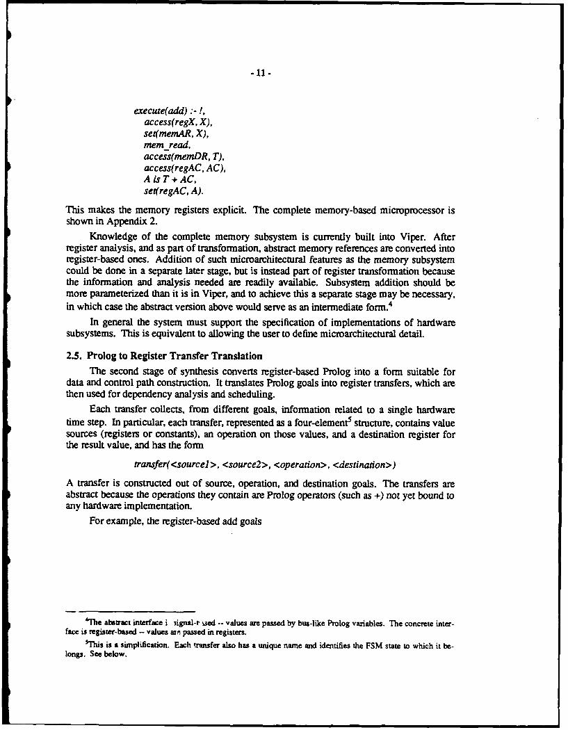
execute(add) :-!,access(regX, X),set(memAR, X),meme read,access(memDR, T),access(regAC, AC),A is T + AC,set(regAC, A).
This makes the memory registers explicit. The complete memory-based microprocessor isshown in Appendix 2.
Knowledge of the complete memory subsystem is currently built into Viper. Afterregister analysis, and as part of transformation, abstract memory references are converted intoregister-based ones. Addition of such microarchitectural features as the memory subsystemcould be done in a separate later stage, but is instead part of register transformation becausethe information and analysis needed are readily available. Subsystem addition should bemore parameterized than it is in Viper, and to achieve this a separate stage may be necessary,in which case the abstract version above would serve as an intermediate form.4
In general the system must support the specification of implementations of hardwaresubsystems. This is equivalent to allowing the user to define microarchitectural detail.
2.5. Prolog to Register Transfer Translation
The second stage of synthesis converts register-based Prolog into a form suitable fordata and control path construction. It translates Prolog goals into register transfers, which arethen used for dependency analysis and scheduling.
Each transfer collects, from different goals, information related to a single hardwaretime step. In particular, each transfer, represented as a four-element5 structure, contains valuesources (registers or constants), an operation on those values, and a destination register forthe result value, and has the form
transfer(<sourcel>, <source2>, <operation>, <destination>)
A transfer is constructed out of source, operation, and destination goals. The transfers areabstract because the operations they contain are Prolog operators (such as +) not yet bound toany hardware implementation.
For example, the register-based add goals
*'he abstract interface i signal-t ised -- values are passed by bus-like Prolog variables. The concrete inter-
face is register-based - values an passed in registers.5 his is a simplification. Each transfer also has a unique name and identifies the FSM state to which it be-
longs. See below.

- 12-
access(regX, X),set(memAR, X),mem read,access(memDR, T),access(regAC, AC),AisT+AC,set(regAC, A).
are converted into the sequence
transfer(regX, none, none, memAR)transfer(none, none, memread, none)transfer(memDR, regAC, +, regAC)
A transfer is constructed out of source, operation, and destination goals; as individualgoals are processed information about them is recorded.
Abstract transfers fit between register-based Prolog and synthesized hardware. Sinceregisters have been allocated by this stage, and ASP does not currently synthesize pipelinecomputations, atomic register transfers are appropriate units for analysis and hardware gen-eration. Dependencies between transfers constrain scheduling, and resources must be allo-cated on the basis of transfers.
This stage also generates a control flow graph, which divides abstract transfers into acollection of basic block linear sequences; each basic block is realized as a state of a finitestate machine. Clause selection is the fundamental conditional construct in Prolog, and mapsstraightforwardly into finite state machine transitions when the control path is constructed.
The relations produced by this stage are a complete representation of the specification.They could serve as input to a simulator that evaluated the control flow graph and associatedtransfers.
2.5.1. Transfer Analysis
This stage scans Prolog specifications, converting each goal into part of an abstracttransfer operation. Each transfer operation is associated with a basic block of transfers.
Each transfer is stored in a relation and has the form
transfer(<identfier>, <block>,<sourcel>, <source2>, <operation>, <destination>).
The identifier is generated by the system and uniquely identifies the transfer.
Prolog goals divide into three classes: sources, operations, and destinations. When asource or operation goal is processed, information about it is recorded. When a destinationgoal is encountered, the relevant source and operation information is retrieved and the com-plete transfer constructed. All source goals are access goals. Destination goals are set goalsand certain computation goals, such as comparisons, that affect control. Prolog variables areused to connect the pieces of goal information. For example, the add goals

- 13-
access(memDR, T),access(regAC, AC),AisT+AC,set(regAC, A).
are represented by the fragments
srcVar(memDR, T).srcVar(re gAC, AC).expVars(T, AC, +, A).dstVar(regAC, A).
By following the chain of Prolog variables back from the dstVar entry, the operation andsource registers can be found and assembled into a single transfer.
The data base of fragments for the example processor can be found in Appendix 3. Thecomplete set of transfers is in Appendix 4.
2.5.2. Control Flow Analysis
As the analyzer processes goals it also accumulates state transition information. It onlyrecords transitions that alter normal linear control flow. These transitions can be conditionalor unconditional.
Consider the simple processor example. It consists of a case dispatch to a collection ofinstruction-specific goals. The dispatch is a conditional transition; the return from a case armis an unconditional one.
Unconditional branches are stored as
branch(<from-block>, uncond, <to-block>).
Conditional branches have the form
branch(<from-block>, cond, <test>).
where <test> is the source of the value that will drive the dispatch. Each arm is stored as
case(<from-block>, <value>, <to-block>).
For example, the execute dispatch example is represented as
branch(blockl, cond, regOP).
and
case(blockl, add, block3).case(block), load, block4).
and the end of the case arms appear as
branch(block3, uncond, block 1).branch(block4, uncond, block1).
From these relations a controlling finite state machine can be constructed.

- 14.
The relations produced by this stage are a complete representation of the specification.They could serve as input to a simulator that evaluated transfer, branch and case entries.
The branch relations for the example processor are in Appendix 4, along with thetransfers.
2.6. Transfer Scheduling
After the system generates abstract transfers it schedules them. It assigns time steps totransfers in an as-soon-as-possible manner, with concurrency limited only by inter-transferdependencies. The data path construction stage has the capability to modify this schedule,based on resource constraints discovered in that stage.
Dependency is defined to be the conflicting use of any register or restricted resource(such as memory). Most inter-transfer dependencies are explicit, involving register uses, andare much like dependencies between variables in software. Dependencies can be implicit,however, because some actions cause side effects. For example, a memory read loads thememory data register, use of memory data requires waiting for the read to complete. Thesystem allows for the definition of implicit dependencies between operations and registers.
The concurrent schedule is easily generated. Transfers are scanned in the order inwhich they were created -- in the serial order of the original Prolog goals. A transfer isassigned to the time step immediately following that of the latest transfer upon which itdepends. Part of the memory subsystem definition includes assertions specifying its implicitdependencies, such as
implicitDependent(mem, memAR).&mplicitDependent(memDR, mem).
To aid the designer, and guide later rescheduling, the stage also creates a dependencydata base. It records dependencies between pairs of transfers and the resources involved.
Appendix 5 contains the dependency data base for the example processor, Appendix 6contains its schedule. Note that the cycle numbers assigned to transfers are relative within ablock - the first cycle of any block is cycle 1.
2.7. Data Path Generation
The third synthesis stage defines data paths based on the requirements of abstracttransfers and their associated schedule. It generates both static information (symbolic func-tional units and bus connectivity) and dynamic information (functional unit use and bus use).
For example, the add transfer and schedule fragment
transfer(op8, blockS, memDR, regAC, +, regAC).cycle(op8, block, 3).
produce the data path elements
elementType(memDR, register).elementType(regAC, register).elementType(dpalu, alu).elementFn(dpalu, add).
and the dynamic binding

- 15-
elementUse(dpalu. add, op8 , block3, 3).
In addition, the buses
busSrc(busl, memDR).busDst(busl, dpaluPortl).busSrc(bus2, regAC).busDst(bus2, dpaluP ort2).busSrc(bus3, dpalu).busDst(bus3, regAC).
are created, as well as the bus bindings
busUse(busl, memDR, dpaluPortl, op8, block3, 3).busUse(bus2, regAC, dpaluPort2, op8, block3, 3).busUse(bus3, dpalu, regAC, opS, block3, 3).
The stage allocates functional units based on the requirements of each time step, creat-ing enough units to execute all operations assigned to that step. It also creates enough busesand connections.
The complete data path data base for the example processor is found in Appendix 7.
2.7.1. Functional Unit Allocation*0 Information generated by the system about functional units can be divided into two
categories, static and dynamic. Static information defines data path structure. Dynamicinformation is time step dependent and binds the operations of abstract transfers to data pathelements.
An operation in a transfer is a Prolog operator (such as +). A functional unit has a type(ALU, for example) and a set of functions it performs (such as add and subtract). Every Pro-log operator the system can process has at least one associated functional unit type and func-tion.
To allocate functional units, the system first scans all transfers, noting all the operationsthat the designs will have to support. It notes operations that can be treated as special cases(such as adding 1 to a register), and operations that are performed in parallel. It then usesheuristics to select an efficient set of functional units. It next it binds individual operations intransfers to specific functional units, and then creates and schedules buses.
2.7.2. ConnectivityBuses are created and scheduled in a manner similar to functional units. The system
produces both static structural information and dynamic binding information. It uses existingbus resources when possible. It considers buses to be bidirectional, but connections (multi-plexers and decoders) to be unidirectional.
Given a collection of functional units and a schedule, the system attempts to generateonly the connectivity necessary to implement that schedule. It examines in turn each timestep's transfers. For each transfer, if its associated registers and functional unit are connectedby buses unused in that time step, those buses are used. Alternatively, if unused buses existbut are not connected to the relevant functional units, the necessary connections are created.Finally, if unused buses are needed they are created and connected.

•16-
To keep the prototype system simple, it does not modify the functional unit scheduleduring bus creation. Also, the number of buses is not constrained, nor is bus regularity (con-necting all registers to the same buses, for example) a factor considered by the system.
2.8. A Structural Description MechanismAfter data path generation, the data path and control path are completely defined. The
information exists, however, in several incrementally generated relations. The final act ofhigh-level synthesis translates that information into a structural hardware description 6 that thelower levels of the ASP system can use. This translation collects various elements from vari-ous relations and packages them into a sequence of data path element declarations and a finitestate machine definition, in both of which all interconnections are explicit and named. Prologstructures and lists are used to package this information.
2.8.1. The Data Path
Instances of element types are created and given names. In addition (unlike variabledefinition), the connectivity between elements must be established.
A structural data path element has a type, a name, and four lists of connections -- inputsfrom other data path elements, outputs to data path elements, inputs from the control path,and outputs to the control path.
In detail, each element declaration has the form
functionalUnit(<type>, <name>,[<list-of-data-input-signals>],[<list-of-data-output-signals>],[<list-of-control-input-signals>J,[<list-of-control-output-signals>]).
The lists of signals indicate connections to be made with other parts of the design. For exam-ple,
functionalUnit(alu, dpalu,[bus], bus2J, [bus3J,[dpaluFn dpaluCinJ, [dpaluSign, dpaluCout).
creates an ALU and binds it to dpalu. SFor every control input signal mentioned in an element statement, a declaration of the
form
controlln(<signal>, <default-input>, [<list-of-inputs>]).
is required. Control input signals are connected to and driven by the control path. This •declaration defines the signal's default value and other possible values it can have. Thenumber of values defines the bit width of the signal. For example,
controlln(dpaluFn, pass, [add, .1).
would appear with the ALU element definition above. S
6A structural description explicitly represents connections between hardware elements. The OCCAM toCMOS project ([OCCAM]) uses DDL as an intermediate form, similar in function to our structural descriptionmechanism; DDL is not, however, strictly structural.
. 17-
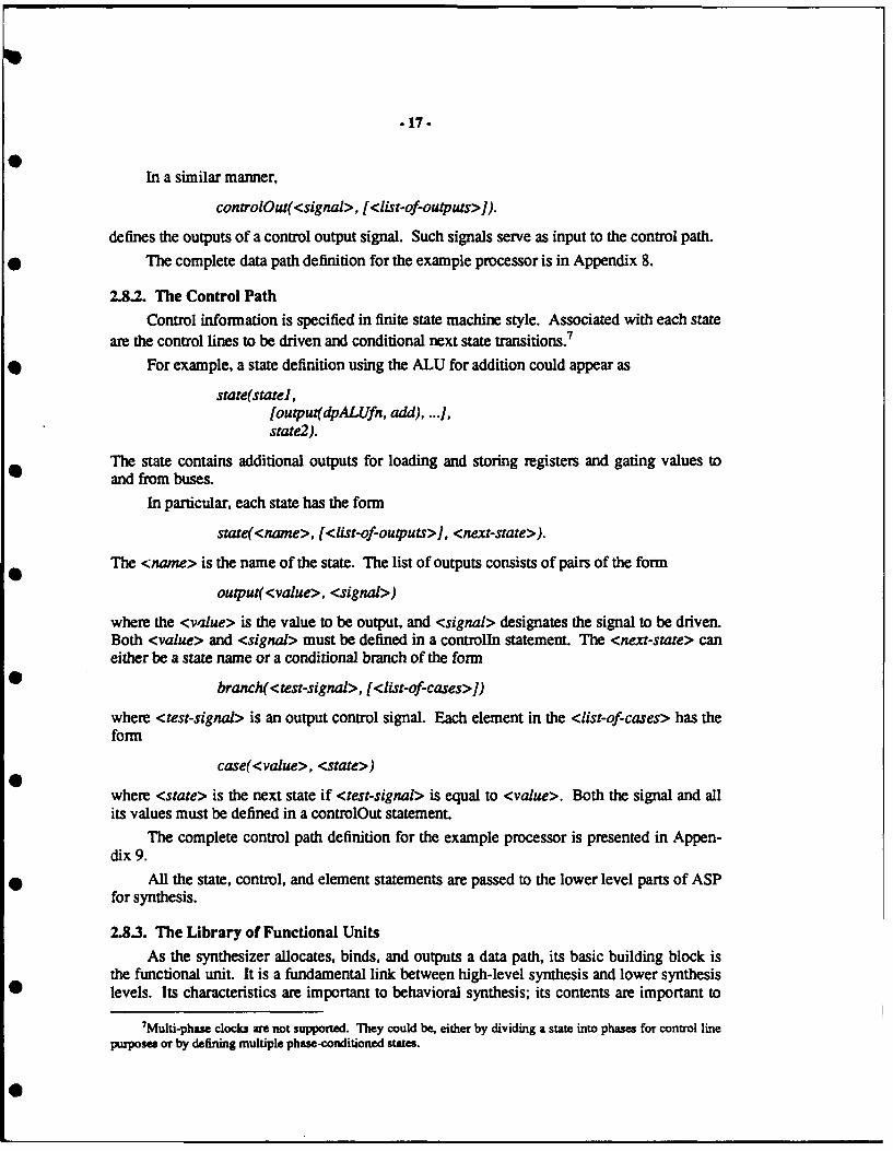
In a similar manner,
controlOut( <signal>, [<list-of-outputs>j).
defines the outputs of a control output signal. Such signals serve as input to the control path.The complete data path definition for the example processor is in Appendix 8.
2.8.2. The Control Path
Control information is specified in finite state machine style. Associated with each stateare the control lines to be driven and conditional next state transitions.7
For example, a state definition using the ALU for addition could appear as
state(statel,[output(dpALUfn, add), .... ,state2).
The state contains additional outputs for loading and storing registers and gating values toand from buses.
In particular, each state has the form
state(<name>, [<list-of-outputs>J, <next-state>).
The <name> is the name of the state. The list of outputs consists of pairs of the form
output(<value>, <signal>)
where the <value> is the value to be output, and <signal> designates the signal to be driven.Both <value> and <signal> must be defined in a controlln statement. The <next-state> caneither be a state name or a conditional branch of the form
branch( <test-signal>, [<list-of-cases>J)
where <test-signal> is an output control signal. Each element in the <list-of-cases> has theform
case(<value>, <state>)
where <state> is the next state if <test-signal> is equal to <value>. Both the signal and allits values must be defined in a controlOut statement.
The complete control path definition for the example processor is presented in Appen-dix 9.
All the state, control, and element statements are passed to the lower level parts of ASPfor synthesis.
2.8.3. The Library of Functional UnitsAs the synthesizer allocates, binds, and outputs a data path, its basic building block is
the functional unit. It is a fundamental link between high-level synthesis and lower synthesislevels. Its characteristics are important to behavioral synthesis; its contents are important to
7Multi-phase clocks are not supported. They could be, either by dividing a state into phases for control linepurposes or by defining multiple phase-conditioned states.
* 18 -
logic and geometrical synthesis. In ASP those characteristics and contents are collected in alibrary of functional units.
The characteristics of a functional unit are its type and the functions it implements. Itscontents are logic equations used by the ASP module generator. From the behavioral point ofview the purpose of a functional unit's characteristics is to guide functional unit selection.
The library also contains implementation details about functional units, in particular thecontrol signal bit patterns used to stimulate specific functions; this information is used by thePLA equation generator. Not all information about functional units is contained in thelibrary; the heuristics that allocate functional units contain knowledge about some functionalunit types, and knowledge about topology is contained in the topology constraint layer dis-cussed below.
The library of functional units can be found in Appendix lOa. The corresponding logicequations used by the lower level module generator can be found in Appendix lob. (This isnot the complete library, but only that part needed for the example processor.)
2.8.4. Lower Level Interfaces
Two lower level interfaces are not strictly part of the Viper system, but they are neces-sary to interface with the rest of ASP, and interact with the library of functional units.
One interface generates and/or logic equations for the ASP PLA generator from controlpath state statements. Enable signals for individual control path outputs are accumulated byscanning all the state statements, and converted into logic equations for specific control bits.Common and and or terms are eliminated from the equations. The equations for the exampleprocessor are shown in Appendix 11.
The. other interface generates topological constraints for the data path module generator,indicating how control and data lines should be placed. Signal lines are also decomposedinto individual bit lines that can be connected to the PLA. The topologically constrained datapath for the example processor is found in Appendix 12.
3. Topolog
Topolog is the module generator and layout engine for ASP. It takes as input a circuitdescription and constraints, and outputs sticks-based layout.
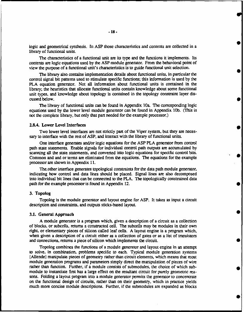
3.1. General Approach •
A module generator is a program which, given a description of a circuit as a collectionof blocks, or subcells, returns a constructed cell. The subcells may be modules in their ownright, or elementary pieces of silicon called leaf cells. A layout engine is a program which,when given a description of a circuit either as a collection of gates or as a list of transistorsand connections, returns a piece of silicon which implements the circuit. S
Topolog combines the functions of a module generator and layout engine in an attemptto solve, in combination, problems specific to each. Typical module generation systems[Allende] manipulate pieces of geometry rather than circuit elements, which means that mostmodule generation programs and parameters simply direct the manipulation of pieces of wirerather than function. Further, if a module consists of submodules, the choice of which sub-module to instantiate first has a large effect on the resultant circuit for purely geometric rea-sons. Folding a layout program into a module generator permits the generator to concentrateon the functional design of circuits, rather than on their geometry, which in practice yieldsmuch more concise module descriptions. Further, if the submodules are expanded as blocks
.19-
and jointly placed and routed, the second problem disappears.
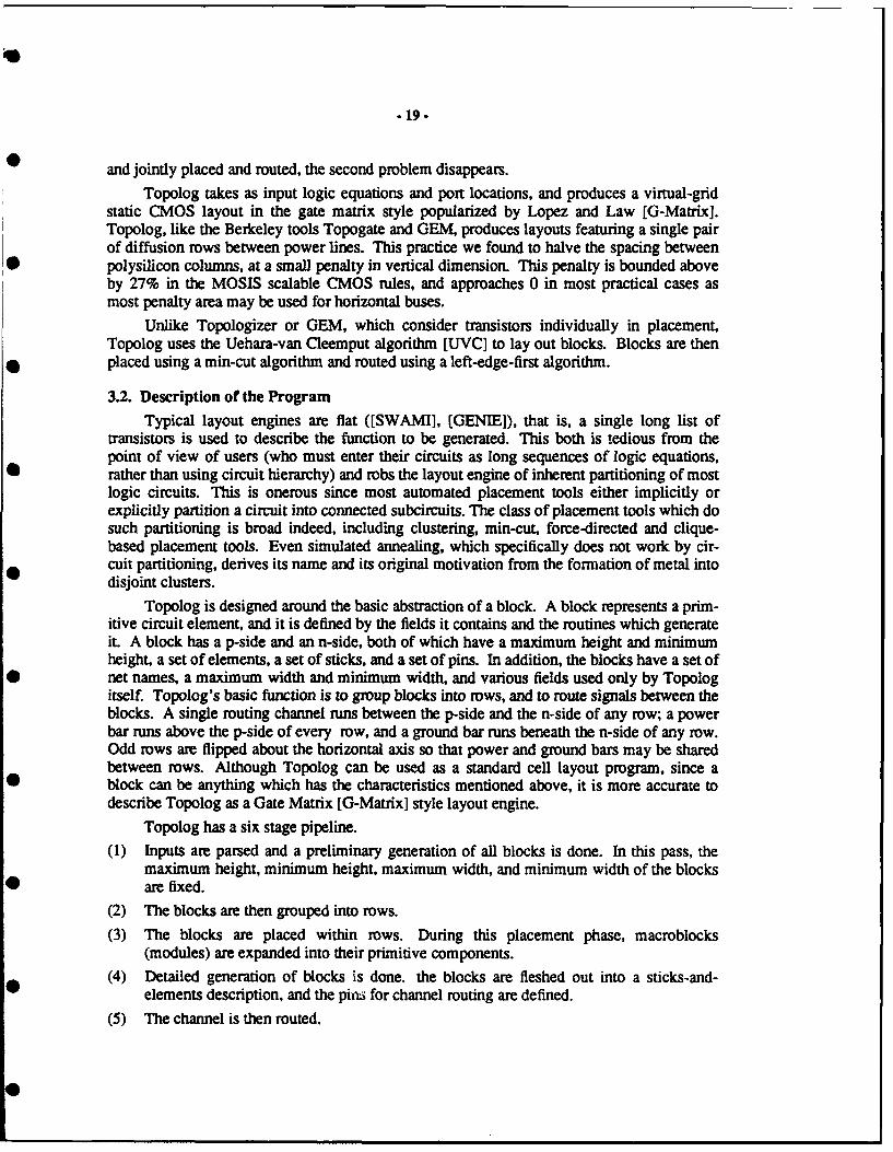
Topolog takes as input logic equations and port locations, and produces a virtual-gridstatic CMOS layout in the gate matrix style popularized by Lopez and Law [G-Matrix].Topolog, like the Berkeley tools Topogate and GEM, produces layouts featuring a single pairof diffusion rows between power lines. This practice we found to halve the spacing betweenpolysilicon columns, at a small penalty in vertical dimension. This penalty is bounded aboveby 27% in the MOSIS scalable CMOS rules, and approaches 0 in most practical cases asmost penalty area may be used for horizontal buses.
Unlike Topologizer or GEM, which consider transistors individually in placement,Topolog uses the Uehara-van Cleemput algorithm [UVC] to lay out blocks. Blocks are thenplaced using a min-cut algorithm and routed using a left-edge-first algorithm.
3.2. Description of the Program
Typical layout engines are flat ([SWAMI], [GENIED), that is, a single long list oftransistors is used to describe the function to be generated. This both is tedious from thepoint of view of users (who must enter their circuits as long sequences of logic equations,rather than using circuit hierarchy) and robs the layout engine of inherent partitioning of mostlogic circuits. This is onerous since most automated placement tools either implicitly orexplicitly partition a circuit into connected subcircuits. The class of placement tools which dosuch partitioning is broad indeed, including clustering, min-cut, force-directed and clique-based placement tools. Even simulated annealing, which specifically does not work by cir-cuit partitioning, derives its name and its original motivation from the formation of metal intodisjoint clusters.
Topolog is designed around the basic abstraction of a block. A block represents a prim-itive circuit element, and it is defined by the fields it contains and the routines which generateit. A block has a p-side and an n-side, both of which have a maximum height and minimumheight, a set of elements, a set of sticks, and a set of pins. In addition, the blocks have a set ofnet names, a maximum width and minimum width, and various fields used only by Topologitself. Topolog's basic function is to group blocks into rows, and to route signals between theblocks. A single routing channel runs between the p-side and the n-side of any row; a powerbar runs above the p-side of every row, and a ground bar runs beneath the n-side of any row.Odd rows are flipped about the horizontal axis so that power and ground bars may be sharedbetween rows. Although Topolog can be used as a standard cell layout program, since ablock can be anything which has the characteristics mentioned above, it is more accurate todescribe Topolog as a Gate Matrix [G-Matrix] style layout engine.
Topolog has a six stage pipeline.
(1) Inputs are parsed and a preliminary generation of all blocks is done. In this pass, themaximum height, minimum height, maximum width, and minimum width of the blocksare fixed.
(2) The blocks are then grouped into rows.
(3) The blocks are placed within rows. During this placement phase, macroblocks(modules) are expanded into their primitive components.
(4) Detailed generation of blocks is done. the blocks are fleshed out into a sticks-and-elements description, and the pins for channel routing are defined.
(5) The channel is then routed.

- 20-
(6) Finally, the complete circuit is converted to a sticks form and the package is output.An abbreviated Topolog pipeline is available when only one row needs to be placed.
This abbreviated pipeline omits placement into rows and vertical channel routing.
3.3. Description of the Algorithms
Topolog is a package consisting of ten modules and about 3000 lines of Prolog code.Of the ten modules, six implement algorithms used in the package, one is a rule-basedmodule to connect the outputs of logic functions formed in the wells to buses in the channelbetween the wells, one generates the sticks description from the internal data structures, oneforms the declarations and generic routines for the data structures used, and one is used tosimulate the extensions to the Prolog language that we found were required to implement thealgorithms we wished to use.
Topolog first reads in and parses a set of facts in Prolog's database which describe theblocks to be laid out. The parsed blocks are then passed to the Uehara-van Cleemput pack-age, which determines transistor order and separation zones within the blocks. The blocksare then passed to the placement routine, which separates them into rows using a min-cutalgorithm modified to consider block size when determining the cut. Once placed, the logicspecifications with transistor placement are translated into a pair of diffusion strips for eachblock. Metal routing is then done over the strips using a left-edge-first channel router. A sim-ple router is all that is required, since pins are on only one edge of the channel.
This routing must be dense, since it is a prime determinant of the vertical pitch of theblock. Further, vias must be minimized, since they contribute heavily to parasitic capaci-tance in the wells. Finally, diffusion must be used as little as possible for routing, since it ishighly capacitive.
The channel router therefore uses metal-I for horizontal routing, and vertical routingwhere the proposed vertical run does not cross a horizontal metal line. Metal-2 is used forvertical routing but not horizontal routing, since it requires a double contact to go down todiffusion. Diffusion is used for other vertical runs.
Once the wells are routed, a rule-based program is invoked to route the output of thegate from the p-well and the n-well into the channel. This program first attempts to ensurethat no track must be added to either well to route the output of the gate into metal-2, asrequired. Its second function is to ensure that the same column is used by both the p-side andthe n-side to route the output to the channel 8 0
The horizontal channels are then routed, again using the simple left-edge first router.The assignment of numbers to rows is then made, and the entire package is output.
3.4. Input FormatThe Topolog input format is a collection of logic equations, each having one of the fol-
lowing forms:
$Once the outputs are routed, the full internal coverage of metal-2 in each row of blocks is known. Channelsare defined for routing between channels. A modified left-edge-first router is used to run lines between the rows,attempting to minimize channel density in the horizontal channels.
-21 -
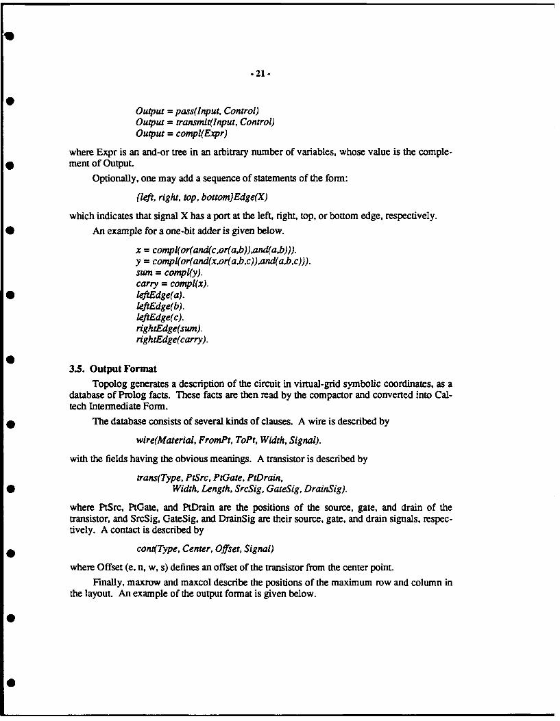
Output = pass(Input, Control)Output = transmit(Input, Control)
Output = compl(Expr)
where Expr is an and-or tree in an arbitrary number of variables, whose value is the comple-ment of Output.
Optionally, one may add a sequence of statements of the form:
(left, right, top, bottom}Edge(X)
which indicates that signal X has a port at the left, right, top, or bottom edge, respectively.
*0 An example for a one-bit adder is given below.
x = compl(or(and(c,or(a,b)),and(a,b))).y = compl(or(and(x,or(a,b,c)),and(a2b,c))).sum = compl(y).carry = compl(x).leftEdge(a).leftEdge(b).leftEdge(c).rightEdge(sum).rightEdge(carry).
3.5. Output FormatTopolog generates a description of the circuit in virtual-grid symbolic coordinates, as a
database of Prolog facts. These facts are then read by the compactor and converted into Cal-tech Intermediate Form.
The database consists of several kinds of clauses. A wire is described by
wire(Material, FromPt, ToPt, Width, Signal).
with the fields having the obvious meanings. A transistor is described by
trans(Type, PtSrc, PtGate, PtDrain,Width, Length, SrcSig, GateSig, DrainSig).
where PtSrc, PtGate, and PtDrain are the positions of the source, gate, and drain of thetransistor, and SrcSig, GateSig, and DrainSig are their source, gate, and drain signals, respec-tively. A contact is described by
cont(Type, Center, Offset, Signal)
where Offset (e, n, w, s) defines an offset of the transistor from the center point.Finally, maxrow and maxcol describe the positions of the maximum row and column in
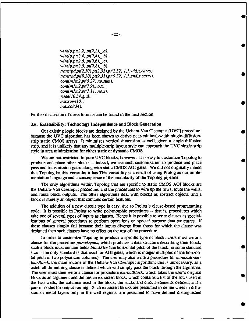
the layout. An example of the output format is given below.
- 22 -
wire(p,pt(2,2),pt(9,2),_,a).wire(p,pt(2,4),pt(9,4),_,b).wire(p,pt(2,6),pt(9,6),_,c).wire(p,p(2,8),pt(9,8),_,b).trans(pdpt(2,30) pt(2,31),pt(2,32),1 ,J ,vdd,x,carry).trans(ndpt(9,30),pt(9,31),pt(9,32),1,1,gnd,x,carry). 0cont(mlm2 pt(5,27),no,sum).cont(m lm2,pt(7,9),no,x).con(mlm2 pt(7,11),no,x).node(1O,34 ,gnd).maxrow( O).maxcol(34).
Further discussion of these formats can be found in the next section.
3.6. Extensibility: Technology Independence and Block Generation
Our existing logic blocks are designed by the Uehara-Van Cleemput [UVC] procedure,because the UVC algorithm has been shown to derive near-minimal-width single-diffusion-strip static CMOS arrays. It minimizes vertical dimension as well, given a single diffusionstrip, and it is unlikely that any multiple-strip layout style can approach the UVC single-stripstyle in area minimization for either static or dynamic CMOS.
We are not restricted to pure UVC blocks, however. It is easy to customize Topolog toproduce and place other blocks -- indeed, we use such customization to produce and placepass and transmission gates along with static CMOS AOI gates. We did not originally intendthat Topolog be this versatile; it has This versatility is a result of using Prolog as our imple-mentation language and a consequence of the modularity of the Topolog pipeline.
The only algorithms within Topolog that are specific to static CMOS AOI blocks arethe Uehara-Van Cleemput procedure, and the procedures to wire up the rows, route the wells,and route block outputs. The other algorithms deal with blocks as abstract objects, and ablock is merely an object that contains certain features.
The addition of a new circuit type is easy, due to Prolog's clause-based programmingstyle. It is possible in Prolog to write polymorphic procedures -- that is, procedures whichtake one of several types of inputs as clauses. Hence it is possible to write clauses as special-izations of general procedures to perform operations on special purpose data structures. Ifthese clauses simply fail because their inputs diverge from those for which the clause wasdesigned then such clauses have no effect on the rest of the procedure.
In order to customize Topolog to produce a specific type of block, users must write aclause for the procedure parselnputs, which produces a data structure describing their block;such a block must contain fields blockSize (the horizontal pitch of the block, in some standard 0size -- the only standard is that used for AOI gates, which is integer multiples of the horizon-tal pitch of two polysilicon columns). The user may also write a procedure for minimalinter-laceBlock, the main routine of the Uehara-Van Cleemput algorithm; this is unnecessary, as acatch-all do-nothing clause is defined which will simply pass the block through the algorithm.The user must then write a clause for procedure extractBlock, which takes the user's originalblock as an argument and defines an extracted block, which contains a list of the rows used in 0the two wells, the columns used in the block, the sticks and circuit elements defined, and apair of nodes for output routing. Such extracted blocks are presumed to define wires in diffu-sion or metal layers only in the well regions, are presumed to have defined distinguished
0:
-23-
wires for Vdd (at the top of the block) and GND (at the bottom of the block), and arepresumed to have obeyed the constraints given by the horizontalWire and verticalWire pro-cedures; unless modified, these are horizontalWire(metail), verticalWire(metal2); the staticCMOS extractedBlock procedure assumes this restriction.
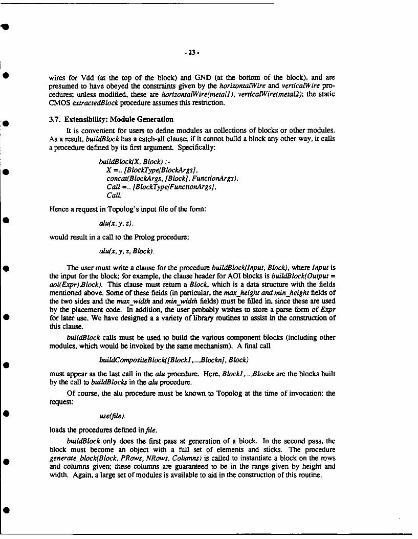
3.7. Extensibility: Module Generation
It is convenient for users to define modules as collections of blocks or other modules.As a result, buildBlock has a catch-all clause; if it cannot build a block any other way, it callsa procedure defined by its first argument. Specifically:
buildBlock(X, Block) :-X =.. [BlockType/BlockArgs],concat(BlockArgs, [Block], FunctionArgs),Call =.. [BlockType/FunctionArgsJ,Call.
Hence a request in Topolog's input file of the form:
alu(x, y, z).
would result in a call to the Prolog procedure:
alu(x, y, z, Block).
The user must write a clause for the procedure buildBlock(Input, Block), where Input isthe input for the block; for example, the clause header for AOI blocks is buildBlock(Output =aoi(Expr),Block). This clause must return a Block, which is a data structure with the fieldsmentioned above. Some of these fields (in particular, the max height and min_height fields ofthe two sides and the max-width and min width fields) must be filled in, since these are usedby the placement code. In addition, the user probably wishes to store a parse form of Exprfor later use. We have designed a a variety of library routines to assist in the construction ofthis clause.
buildElock calls must be used to build the various component blocks (including othermodules, which would be invoked by the same mechanism). A final call
buildC ompositeBlock([Blockl,...,Blockn], Block)
must appear as the last call in the alu procedure. Here, Blockl,... .Blockn are the blocks builtby the call to buildBlocks in the alu procedure.
Of course, the alu procedure must be known to Topolog at the time of invocation; therequest:
use(file).
loads the procedures defined infile.
buildBlock only does the first pass at generation of a block. In the second pass, theblock must become an object with a full set of elements and sticks. The proceduregenerateblock(Block, PRows, NRows, Columns) is called to instantiate a block on the rowsand columns given; these columns are guaranteed to be in the range given by height andwidth. Again, a large set of modules is available to aid in the construction of this routine.
.24.
No other clauses are required for module construction, since the placement routinesbreak modules into their component parts before the blocks are actually generated; hencegenerateBlock clauses need only be supplied for primitive blocks.
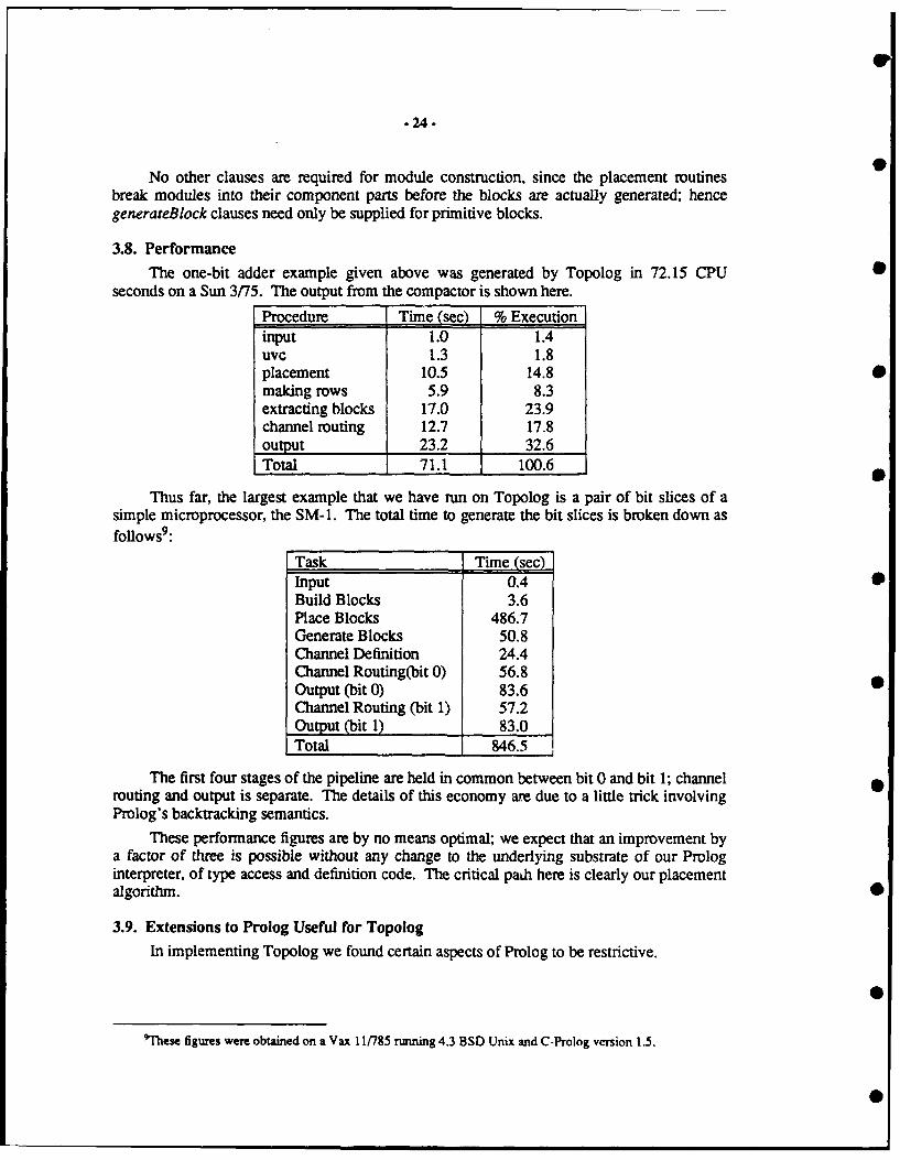
3.8. PerformanceThe one-bit adder example given above was generated by Topolog in 72.15 CPU 0
seconds on a Sun 3/75. The output from the compactor is shown here.
Procedure Time (see) % Executioninput 1.0 1.4uvc 1.3 1.8placement 10.5 14.8 0making rows 5.9 8.3extracting blocks 17.0 23.9channel routing 12.7 17.8output 23.2 32.6Total 71.1 100.6
Thus far, the largest example that we have run on Topolog is a pair of bit slices of asimple microprocessor, the SM-1. The total time to generate the bit slices is broken down asfoUows9:
Task Time (sec)Input 0.4 0Build Blocks 3.6Place Blocks 486.7Generate Blocks 50.8Channel Definition 24.4Channel Routing(bit 0) 56.8Output (bit 0) 83.6Channel Routing (bit 1) 57.2Output (bit 1) 83.0Total 846.5
The first four stages of the pipeline are held in common between bit 0 and bit 1; channelrouting and output is separate. The details of this economy are due to a little trick involvingProlog's backtracking semantics.
These performance fiures are by no means optimal; we expect that an improvement bya factor of three is possible without any change to the underlying substrate of our Prologinterpreter, of type access and definition code. The critical path here is clearly our placementalgorithm.
3.9. Extensions to Prolog Useful for TopologIn implementing Topolog we found certain aspects of Prolog to be restrictive.
'These figures were obtained on a Vax 11785 running 4.3 BSD Unix and C-Prolog version 1.5.
- • m i

-25-
3.9.1. Structural Replacement
The major problem we encountered was the assign-once nature of Prolog. TheKernighan-Lin min-cut algorithm works by exchanging blocks across a partition; in order forthe algorithm to function, then, each block must contain a component which indicates whichside of the partition a block is currently on. Further, in order for the cost of an exchange to becomputed quickly and accurately, each net must contain a list of the blocks it is incident uponand each block must contain the list of nets incident upon it. When a block is moved acrossthe partition, the component indicating which side it is on must be changed. This requiresgenerating a new block. This block is contained in some set of nets, each of which must beregenerated. These nets in turn are contained in some set of blocks, each of which must beregenerated. Potentially, this may continue until each block and each net has been regen-erated, all to adjust one field in one block.
The solution we adopted simulates multiple assignment in an assign-once language. Ineach component of a data structure, instead of storing the actual value we store a value struc-ture, the first field of which is the value of the component, and the second an unbound vari-able. The value of the component is set by the following code:
setVal(U, X)var(U), !,U = valStruct(X, .
setVal(valStruct(_, U), X)setVal(U, X).
and the value is accessed by the following code:
accessVal(valStruct(U, X), U)var(X),
accessVal(valStruct(_, X), Y)accessVal(X, Y).
Broadly, setVal chases recursively through the valStructs until it reaches an unboundvariable, which it sets to the valStruct of the new value and an unbound variable; accessValchases through the valStructs until it finds one with an unbound variable as the second argu-ment; it then returns the first argument of the valStruct.
The effect of this storage method is the provision of multiple assignment in a single-assignment language, and it permits the efficient implementation of standard CAD algorithmsin Prolog. There are two principal costs of this method. First, assignment or access to astructure component becomes an O(n) rather than an 0(1) operation, where n is the numberof assignments to the component. In practice, this is not too onerous a cost; measurements onTopolog have shown that the median depth of a valStruct is 1, and the mean slightly over I;the maximum in our programs has been 5.
The second disadvantage is that unification cannot be used to build or access structuresthat contain vaIStructs, since unification will not return the value of a component but rather avaIStruct. Since we prefer the use of the field macro described above, it was easy to writeaccessField and setField, a straightforward combination of the field macro with the two pro-cedures described above.
We would prefer a weak form of destructive assignment, which we call structuralreplacement, over value structures. In particular, as we have shown [rplacarg], in a

-26-
networked data structure (a data structure in which some node is shared by two or more othernodes), modification of the data structure without structural replacement can cost up to O(logn), where n is the number of nodes in the data structure, no matter how the data structure isstored. Since we can generate one node in a single data structure for each step of any algo-rithm, the performance penalty is bounded below by O(log n) for any algorithm implementedwithout structural replacement.
The form of the structural replacement operator that we prefer is simple. We would likean operator that would replace transparently only arguments of structures (since the lack of adestructive assignment operator for atomic variables is not only benign, but, given the logicalvariable, necessary for any reasonable semantics of a Prolog program), and whose workwould be undone on backtrack, since we feel that any operation not undone on backtrack isdestructive of Prolog semantics. The SICStus Prolog setarg operator meets these require-ments [SICStus].
3.9.2. Arrays
Multidimensional arrays are required for some of the algorithms used within Topolog,and hence we sought a method of array implementation. Once the value structure and datastructure code above were in place, implementation of array code became relatively straight-forward. An array is merely a structure of size equal to the number of elements of the array,and a small associated data structure which maps a given index vector to an array element.The difficulties in implementing arrays in Prolog have traditionally been a desire to avoidrecopying the entire array when any element is changed; this is precisely the purpose of set-Val and accessVal, and hence this difficulty is solved for us.
3.9.3. Circular Data Structures
Topolog manipulates both circuit elements (blocks) and their connections (nets). Eachnet contains a list of all blocks incident upon the net, and each block contains a list of all netsincident upon it, giving rise to a circular data structure.
In C-Prolog, however, every attempt to create this structure resulted in an infinite loopin the unification routine; eventually, we gave up, and stored only the net names in theblocks, and looked up the actual nets in a balanced tree sorted by net name -- a cost of Q(logn) for each (logical) pointer traversal.
3.9.4. Data Types
Unification is used in Prolog to create and access data structures. When programs aresmall, or the data structures that they create or access are small, or each data structure is usedonly within a single module, this is straightforward. We found, however, that the most con-venient way to program Topolog was to create a single data structure, the block, with a largenumber of fields; each module selectively filled in fields of the block. This organizationmeant that whenever a field was added to the block definition (a common occurrence in pro-gram development), the field had to be added in every clause where the block structureappeared, an onerous task, and one that led to the introduction of many bugs.
The solution we adopted was to add a typedef procedure, called when a file is loaded.typedef takes a structure as its argument, and defines a clause in the procedure makeStruct,which builds an instance of the data structure and clauses in the procedure field, which inturn, when given an instance of a data structure and the name of a field within the structure,returns the value of that field. Once typedef was implemented, data structures proved easy tomodify, and a major difficulty in programming was removed, field proved to be the

-27-
procedure most called in Topolog; almost 600 lines of code directly reference it. Sixteenmajor data types are defined in Topolog, with the number of fields varying from 2 to 19.These data types are often widely shared among various procedures.
4. Sticks-Pack
In this section we present Sticks-Pack (SP), a design environment for VLSI circuit lay-out generation written exclusively in Prolog. Not only does Prolog provide a relational data-base for VLSI objects, it also provides a syntax well suited for expressing both algorithmsand rules. Although SP is a component of ASP, it can also be used by human designers. TheSP environment consists of a technology independent compactor that creates spaced layoutand simulation data files from symbolic sticks, a joiner that joins together cells generated bythe compactor, and a switch level simulator.
4.1. The System
Current layout systems are composed of programs that have been written independentlyof each other. This often results in a duplication of work and a need for conversion programs.The programs within the SP system have been designed to work together. For example,while spacing the elements from a cell file, the compactor saves all the elements on theborder of the cell into a border file for the joiner. The joiner can then space cells properlywithout again searching through each cell for border elements. This is in contrast to othersystems where the program that compacts cells is written independently of the program thatjoins cells.
Previous approaches to integrated VLSI design environments were generally basedupon conventional programming languages using custom data managers with strict data for-mats ([OCT], (Symbolic-IC]). Objects in these data managers can only be generated througha fixed data field. For example, many databases group wires by layer. To find wires of thesame layer, one simply calls a generator that returns instances of wires that are of the queriedlayer. However, if one wants to find all the wires of an electrical node, one cannot simplycall a generator to generate the wires of the node. One must first generate the wires by layerand then filter out the wires that are not of the desired node [OCT]. By using the relationaldatabase inherent in Prolog, SP allows generation of objects by any arbitrary number of datafields. Furthermore, individual data fields may be represented by objects. This allowsspecific fields to be parameterized. For example, the W/L ratio of an output transistor in acell can be expressed as a parameter and modified without any knowledge of the location ofthe transistor. This gives the CAD designer a simple but powerful method of accessing data.
Topolog generates male and female single tier cells (cells composed of one p-strip andone n-strip). These cells are individually compacted by the SP compactor, joined so that then-well from the male cell and the n-well from the female cell share a ground rail, and thenarrayed by the joiner.
4.2. The Compactor
The SP compactor takes a cell defined in the Sticks In Prolog (SIP) language andcreates a mask level representation for the cell using a new compaction technique that is bothalgorithmic and rule based. An algorithm similar to zone refining [Zone] is used to perform arough spacing of the elements. For each compaction pass, a floor and ceiling profile for eachlayer of material is maintained. In zone refining each element is moved from the ceilingprofile to an optimum site on the floor. The SP compactor moves elements directly across the'molten region' to the floor, where spacing requirements are satisfied, and diagonal
-28-
constraints are noted. Rules are then employed to shift elements for a better fit within theirenvironment. By resolving diagonal constraints after the horizontal and vertical compactionpasses have completed, the compactor can relieve each constraint by adding space in eitherthe vertical or the horizontal direction, whichever costs less. By treating each layout elementas an object, the compactor can easily interpret new layout objects such as bipolar transistorelements to suit mixed technology processes.
For each cell, a connectivity file containing nodal connectivity, resistivity and capaci-tance information is generated for the simulator and for Spice. The SP compactor is rela-tively technology independent. A design rule file and a set of technology dependent rules arespecified for each technology.
4.3. The Joiner
Large layouts in SP are realized by joining small cells together with the joiner. Leafcells (cells of the lowest level consisting only of transistors and wires) are compacted indivi-dually and are the building blocks for larger modules. There are two methods for joiningcells, pitchmatching and river routing. Pitchmatching causes expansion in one axis, whileriver routing causes expansion in the other. Previous tilers have either exclusively pitch-matched or river routed cells together [V-Grid]. The joiner program connects signalsbetween a given pair of cells by either pitchmatching or river routing, whichever is more areaefficient. Directional constraints can override the joiner (that is, if a horizontal constraint isplaced, the joiner will river route all signals joined vertically, and pitchmatch all signalsjoined horizontally). The joiner operates in the physical domain rather than the virtual griddomain for tighter results. This also allows cells of various virtual grid heights and widths tobe joined.
4.4. The Simulator
The built-in switch level simulator simulates the operation of cells compacted by thecompactor or cells joined by the joiner. The simulator asserts given input values at the inputnodes and propagates those values to all the other nodes throughout the circuit. Feedbackpaths are noted and their nodal values are saved for calculation of the next state. The simula-tor is unique in that it makes extensive use of Prolog backtracking for determining the valueof nodes within a circuit.
4.5. The Design Environment
There are many characteristics of CAD elements that make them difficult to represent ina database [CAD-DBI, [VLSI-DB]. Each element has many features that associate it withother elements. For example, a wire may be related to other wires by node, by layer, and bylocation. A CAD tool should be able to select elements by any features as well as assign newfeatures and relations.
A VLSI database must:" Provide a method for representing objects and structures as well as relations between
objects.
• Provide an abstraction to allow the user to access data efficiently without burdening theuser with details of operation.
" Interface well with the programming environment. The programming language must bepowerful enough to manipulate data efficiently.
• • • • m | | |0

-29-
The relational database inherent in Prolog is well suited for meeting these requirements.
4.5.1. Prolog as a Database
To model the many complex CAD structures as well as the relationships between struc-tures, many CAD environments use object oriented databases. CAD elements, whether theybe geometry for a compactor, transition states for a simulator, or logic expressions for a logicminimizer, can all be expressed in terms of objects. Relationships between the elements canbe expressed in terms of groups. For example, elements in a cell can be grouped by node orby location as well as by layer. Current object oriented databases for CAD have strict setrelations [OCT]. For exaiile, many databases categorize wires by layer but not location.To find wires of the same layer, one simply calls a generator that returns instances of wiresthat are of the queried layer. But to find wires of the same grid, one cannot simply generatewires based upon the grid information, but must generate wires by layer and filter out thewires that are not of a common grid. Data in Prolog can be linked by both structure andvalue. Thus the procedure for generating all wires on the metal-I layer is the same as theprocedure for generating all wires on row 5, or all wires of node vdd, or all wires of row 5and node vdd in metal-l. Data can also be stored in structures (such as binary trees or sortedlists) for faster access. These constructs provide the ASP Prolog database with a flexible syn-tax. Elements ranging from behavioral descriptions to logic equations to an ALU layout areall directly expressed in and referenced through Prolog.
4.5.2. Sticks in Prolog
Sticks in Prolog (SIP) is a grid based sticks representation in Prolog that supportshierarchy and parameterized elements. Module generators or human designers generate SIPfiles which are converted to mask geometry by the Sticks-Pack compactor. In SIP, VLSI ele-ments are modeled as facts. Attributes for the elements are represented as atoms within thefacts. There are four types of facts in SIP:
wire(Layer, pt(XJ, YI), pt(X2, Y2), Width, Net).cont(Type, pi(X), YI), Offset, Net).transistor (Type, pt(SXJ, SYI), pt(GX2, GY2), pt(DX3, DY3),
Width, Length, Nets, Netg, Netd).pin(Layer, pt(XJ, YI), Element).
Layer can be one of the atoms ml, m2, p, pd, nd. These represent the physical layers ofthe element (metal-l, metal-2, poly, p-diffusion, and n-diffusion).
Contact types can be one of the atoms mlm2, mlpd, mind, mip (metal-l-to-metal-2,metal-l-to-p-diff, metal-l-to-n-diff, metal-l-to-poly). Contact offsets can be one of theatoms nw, nn, ne, ee, se, ss, sw, ww, nof (northwest, north, northeast, east, southeast, south,southwest, west, none).
Width, Length, and X and Y coordinates are integers. pt(X, Y) represents a point loca-tion at (X, Y). The Net field is an atom that is the node name of the element, representing itsconnectivity. Elements of the same node are electrically connected. Nodal information issupplied by the cell generator or can be extracted by a net extractor.
Transistors have 3 point locations, one for the source, one for the gate, and one for thedrain. They also have three nodes, one for each terminal.
The Element field for pins contains the element that the pin is attached to.
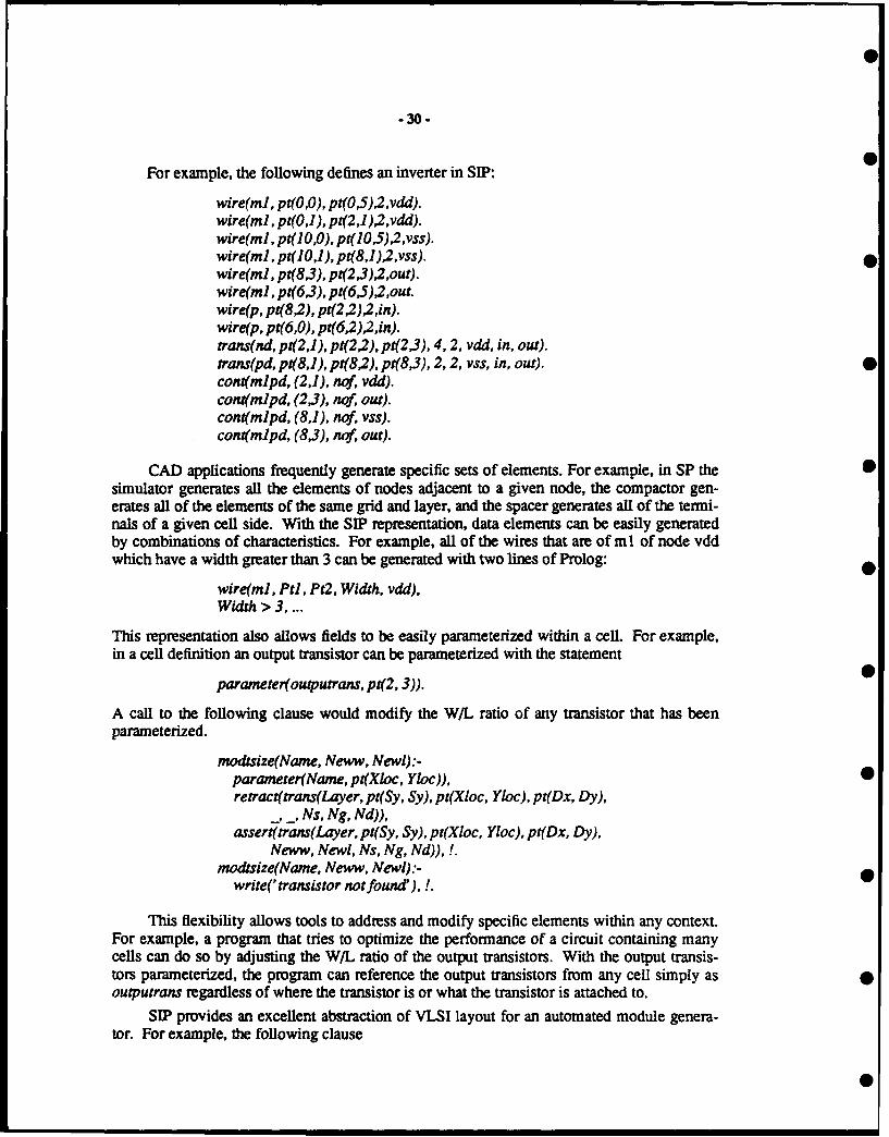
-30-
For example, the following defines an inverter in SIP:
wire(mJ, pt(O,O), pt(O5)2,vdd).wire(ml, pt(O,1), pt(2,1)2,vdd).wire(ml, pt(O,O), pt(10,5),2,vss).wire(m1, pt(O,1), pt(8,1),2,vss).wire(mJ, pt(8,3), pt(2,3)2,out).wire(ml, pt(6,3), pt(6,5) 2,out.wire(p, pt(8,2), pt(22)2,in).wire(p, pt(6,O), pt(6,2),2,in).trans(nd, pt(2,1), pt(2 2). pt(2,3), 4, 2, vdd, in, out).trans(pd, pt(8,1), pt(8,2), pt(8,3), 2, 2, vss, in, out).conl(mlpd, (2,1), no, vdd).con(mlpd, (23), nof, out).cont(mlpd, (8,1), nof, vss).cont(mlpd, (8,3), no, out).
CAD applications frequently generate specific sets of elements. For example, in SP thesimulator generates all the elements of nodes adjacent to a given node, the compactor gen-erates all of the elements of the same grid and layer, and the spacer generates all of the termi-nals of a given cell side. With the SIP representation, data elements can be easily generatedby combinations of characteristics. For example, all of the wires that are of ml of node vddwhich have a width greater than 3 can be generated with two lines of Prolog:
wire(ml, Pt), Pt2, Width, vdd),Width > 3, ...
This representation also allows fields to be easily parameterized within a cell. For example,in a cell definition an output transistor can be parameterized with the statement
parameter(outputrans, pt(2, 3)).
A call to the following clause would modify the W/L ratio of any transistor that has beenparameterized.
modtsize(Narne, Neww, Newl):-parameter(Name, pt(Xloc, Yloc)),retract(trans(Layer, pt(Sy, Sy), pt(Xloc, Yloc), pt(Dx, Dy),
.. ,Ns, Ng, Nd)),assert(trans(Layer, pt(Sy, Sy), pt(Xloc, Yloc), pt(Dx, Dy),
Neww, Newl, Ns, Ng, Nd)), !.modtsize(Nane, Neww, Newl).'-
write(' transistor not found'),!.
This flexibility allows tools to address and modify specific elements within any context.For example, a program that tries to optimize the performance of a circuit containing manycells can do so by adjusting the W/L ratio of the output transistors. With the output transis-tors parameterized, the program can reference the output transistors from any cell simply asoutputrans regardless of where the transistor is or what the transistor is attached to.
SIP provides an excellent abstraction of VLSI layout for an automated module genera-tor. For example, the following clause

-31.
makeinvert(Vddgrid, Vssgrid, Ingrid, Outgrid, Pw, Pl, Nw, NI):-Pdgrid is Vddgrid - 1,Ndgrid is Vssgrid + 1,assert(wire(ml, pt(2, Vddgrid), pt(2 , Pdgrid), 1, unk)),assert(wire(mJ, pt(2, Vssgrid), pt(2, Ndgrid), 1, unk)),
* assert(wire(ml, pt(1, Vddgrid), pt(5, Vddgrid), 1, unk)),assert(wire(ml, pt(1, Vssgrid), pt(5, Vssgrid), 1, unk)),assert(wire(m1, pt(4, Pdgrid), pt(4, Ndgrid), 1, unk)),assert(wire(ml, pt(4, Outgrid), pt(5, Outgrid), 1, unk)),assert(wire(p, pt(3, Pdgrid), pt(3, Ndgrid), 1, unk)),assert(wire(p, pt(O, Ingrid), pt(3, Ingrid), 1, unk)),assert(cont(mld, pt(2, Pdgrid), nof, unk)),assert(cont(mld, pt(2 , Ndgrid), nof, unk)),assert(cont(mld, pt(4, Pdgrid), nof, unk)),assert(cont(mld, pt(4, Pdgrid), nof, unk)),assert(trans(pd, pt(l, Pdgrid), pt(2, Pdgrid), pt(3, Pdgrid),
* Pw, PLunk, unk, unk)),assert(trans(nd, pt(1, Ndgrid), pt(2, Ndgrid), pt(3, Ndgrid),
Nw, Nlunk, unk, unk)), !.
will generate an arbitrarily sized inverter with variable input and output locations. Nodalinformation is deduced by the extractor. ROMs, PLAs, and other modular layout styles canbe generated in a similar fashion.
4.5.3. Language and Data Integration in PrologMost CAD applications rest upon a database substrate. They do not, however, rest uni-
formly on the substrate. The line defining the facilities of the CAD data manager would, inan ideal world, be drawn differently for each application. In the real world of separate data-
* bases and application programs the capabilities of the CAD data manager must be definedonce, and not vary by application.
In the Prolog world, the line between database and application is hazy, and often tran-sparent. In Prolog there is no syntactic or semantic difference between a procedure call and adatabase query.
* Design rules specify the distances between elements. In the compactor these rules areexpressed as facts, such as
space(poly, pd, 2).space(poly, nd, 2).space(pd, nd, 2).
The order in which the layers appear does not matter (for instance, the poly to pd spacing isthe same as pd to poly spacing). A simple procedure referencing the space facts will makethem order independent.
0
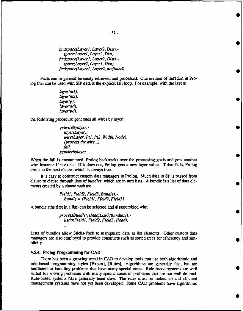
.32 -
findspace(Layerl, Layer2, Dist) :-space(Layerl, Layer2, Dist).
findspace(Layerl, Layer2, Dist) :-space(Layer2, Layer], DisO.
findspace(Layerl, Layer2, notfound).
Facts can in general be easily retrieved and processed. One method of iteration in Pro-log that can be used with SIP data is the explicit fail loop. For example, with the layers
layer(ml ).layer(m2).layer(p).layer(nd).layer(pd).
the following procedure generates all wires by layer
getwirebylayer:-layer(Layer),wire(Layer, Ptl, Pt2, Width, Node),(process the wire...)fail.
getwirebylayer.
When the fail is encountered, Prolog backtracks over the processing goals and gets anotherwire instance if it exists. If it does not, Prolog gets a new layer value. If that fails, Prologdrops to the next clause, which is always true.
It is easy to construct custom data managers in Prolog. Much data in SP is passed fromclause to clause through lists of bundles, which are in turn lists. A bundle is a list of data ele-ments created by a clause such as:
Field), Field2, Field3, Bundle):-Bundle = [Field], Field2, Field3J.
A bundle (the first in a list) can be selected and disassembled with
processBundle([HeadListOfBundles]):-listio(Fieldl, Field2, Field3, Head),
Lists of bundles allow Sticks-Pack to manipulate data as list elements. Other custom datamanagers are also employed to provide constructs such as sorted trees for efficiency and sim-plicity.
4.5.4. Prolog Programming for CADThere has been a growing trend in CAD to develop tools that use both algorithmic and
rule-based programming styles [Expert], [Rules]. Algorithms are generally fast, but areinefficient at handling problems that have many special cases. Rule-based systems are wellsuited for solving problems with many special cases or problems that are not well defined.Rule-based systems have generally been slow. The rules must be looked up and efficientmanagement systems have not yet been developed. Some CAD problems have algorithmic

-33 -
solutions (such as simulation), but most are computationally expensive (such as routing andlogic minimization), and can be solved by a host of approximation techniques, includingrule-based heurisics.
Prolog provides an environment for both algorithmic and rule-based programmingstyles. Its clausal nature allows rules to be easily updated or modified. Algorithms can beexpressed quickly and easily, which makes Prolog an ideal language for rapid prototyping.
A current philosophy in CAD systems is to develop CAD tools that are 'technologyindependent' or 'technology insensitive'. Tools have been developed with informationregarding technology expressed as a set of parameters, with the data for a certain technologyloaded from a technology file. Because of this, the tools have not been able to utilize fullybenefits that certain technologies have to offer. For example, in the automatic generation ofrandom logic metal-1 to metal-2 vias are expensive in area. In certain technologies, the areaof diffusion between two series transistors is an ideal site for the via as metal-I and metal-2are both routable to the site and the spacing between the transistors is about the same as thesize of the via. Such a condition is difficult to express algorithmically and is very technologydependent, but would be useful in minimizing area. The SP compactor supplements its set oftechnology parameters with a set of rules that allow the compactor to compact cells moretightly.
4.5.5. Prolog Programming Methodology Employed by Sticks-Pack
Three basic formats for Prolog clauses are employed by SP:Deterministic Clauses. These clauses work to achieve a certain value or state without
failing.
Filtering Clauses. These clauses, given a set of data elements, interpret each elementdifferently depending upon the values of certain data fields. If-then and case constructs canbe expressed through these clauses.
Generator Clauses. These clauses generate an element or set of elements throughbacktracking.
An example of a deterministic clause is the mindist procedure. It finds the minimumspacing distance between two objects of specified layer and width. The space procedurereturns the minimum spacing distance between two layers, and the width procedure deter-mines the minimum width of a layer.
mindist(Layerl, Width], Layer2, Width2, Distbetwnobjcts):-space(Layerl, Layer2, Distance),width(Layerl, Widthspacel),Widthmodl is Widthl*Widthspacel,width(Layer2, Widthspace2),Widthmod2 is Width2*Widthspace2,Distbetwnobjcts is Widthmodl + Widthmod2 + Distance.
An example of filtering clauses is the checkconstr procedure. It determines how tospace two elements. Each clause filters out a certain condition. If the elements are on thesame row, the spacing is irrelevant. If the elements are contacts, they cannot be stacked uponeach other and must be spaced accordingly. If the elements are not contacts and are of thesame node, the spacing does not matter. Otherwise the elements must be spaced.

-34 -
checkconstr(Layerl, Width), Node], Row], Layer2, Width2, Node2)Rowl=Row2.
checkconstr(Layerl, Width), Node], Rowl, Layer2, Width2, Node2)contacts(Layer), Layer2), ...
checkconstr(Layerl, Width), Node), Row), Layer2, Width2, Node2)Nodel =Node2.
checkconstr(Layerl, Width), Node), Row], Layer2, Width2, Node2)
An example of generator clauses is the makebox procedure. It creates boxes from vari-ous elements, first processing wires, followed by contacts and transistors.
makebox:-wire(Layer, pt(X), Y)), pt(X2, Y2), Wid, Node),
fail.makebox :-
cont(Type, pt(Row, Y), Oset, 9,
fail.makebox:-
trans(Type, pt(Sx, Sy), pt(Gx, Gy), pt(Dx, Dy), W, L, Sn, Gn, Dn),
fail.
makebox.
All of the procedures in SP employ a combination of these three basic formats.
5. The New Version of ASP 0The new version of ASP currently being completed is aimed at solving three problems
with the prototype: generality, maintainability, and speed.
Generality was a problem with the prototype system because it was not designed to sup-port complex designs. In particular, input specifications were constrained to have a singleloop and a single case dispatch. Furthermore, the system could only generate data paths in 0which all bit slices were identical. These limitations required new Prolog translation codeand a new data path generator.
Maintainability was a problem because some of the code would not port from C-Prologto Quintus Prolog, which was necessary to take advantage of Quintus garbage collection. Inparticular, the Topolog module generator had to be replaced because of this problem.
Execution speed was a problem in general with the lower level tools, which had to dealwith thousands of geometric elements, and were orders of magnitude slower than equivalentC programs. In particular, we have rewritten the compactor to use lists instead of assert andretract, in a successful effort to improve its performance.
In addition to addressing the above problems, the reimplementation also caused achange in the system's structure. In the prototype system behavioral and boolean synthesis 0were combined. In the current system they have been split, which clarifies the separate issuesraised at each level.
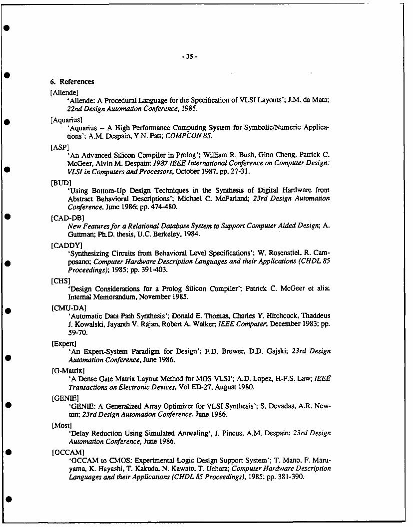
-35-
6. References
[Allende]'Allende: A Procedural Language for the Specification of VLSI Layouts'; J.M. da Mata;22nd Design Automation Conference, 1985.
[Aquarius]'Aquarius - A High Performance Computing System for Symbolic/Numeric Applica-tions'; A.M. Despain, Y.N. Patt; COMPCON 85.
[ASP]'An Advanced Silicon Compiler in Prolog'; William R. Bush, Gino Cheng, Patrick C.McGeer, Alvin M. Despain; 1987 IEEE International Conference on Computer Design:VLSI in Computers and Processors, October 1987, pp. 27-3 1.
[BUD]'Using Bottom-Up Design Techniques in the Synthesis of Digital Hardware fromAbstract Behavioral Descriptions'; Michael C. McFarland; 23rd Design AutomationConference, June 1986; pp. 474-480.
[CAD-DB]New Features for a Relational Database System to Support Computer Aided Design; A.Guttman; Ph.D. thesis, U.C. Berkeley, 1984.
[CADDY]'Synthesizing Circuits from Behavioral Level Specifications'; W. Rosenstiel, R. Cam-posano; Computer Hardware Description Languages and their Applications (CHDL 85Proceedings); 1985; pp. 391-403.
[CHS]'Design Considerations for a Prolog Silicon Compiler'; Patrick C. McGeer et alia;Internal Memorandum, November 1985.
[CMU-DA]'Automatic Data Path Synthesis'; Donald E. Thomas, Charles Y. Hitchcock, ThaddeusJ. Kowalski, Jayanth V. Rajan, Robert A. Walker, IEEE Computer, December 1983; pp.59-70.
[Expert]'An Expert-System Paradigm for Design'; F.D. Brewer, D.D. Gajski; 23rd DesignAutomation Conference, June 1986.
[G-Matrix]'A Dense Gate Matrix Layout Method for MOS VLSI'; A.D. Lopez, H-F.S. Law; IEEETransactions on Electronic Devices, Vol ED-27, August 1980.
[GENIE]'GENIE: A Generalized Array Optimizer for VLSI Synthesis'; S. Devadas, A.R. New-ton; 23rd Design Automation Conference, June 1986.
[Most]'Delay Reduction Using Simulated Annealing', J. Pincus, A.M. Despain; 23rd DesignAutomation Conference, June 1986.
[OCCAMI'OCCAM to CMOS: Experimental Logic Design Support System'; T. Mano, F. Maru-yama, K. Hayashi, T. Kakuda, N. Kawato, T. Uehara; Computer Hardware DescriptionLanguages and their Applications (CHDL 85 Proceedings), 1985; pp. 381-390.
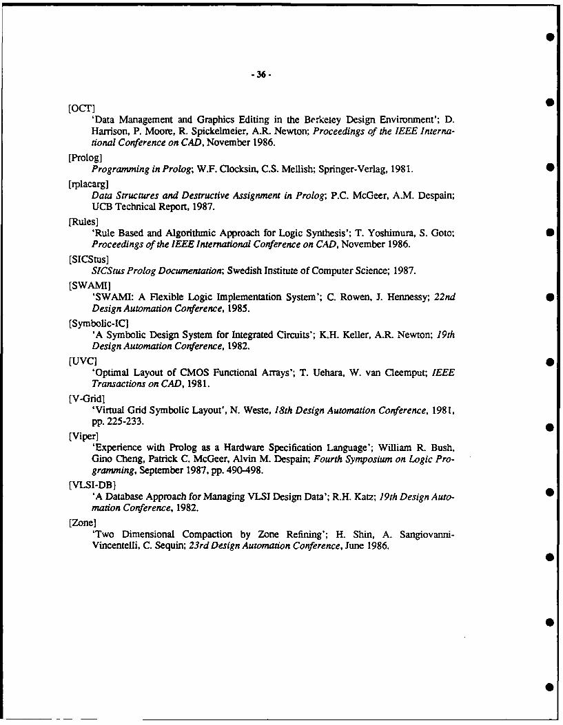
.36-
[OCr] 0'Data Management and Graphics Editing in the Berkeley Design Environment'; D.Harrison, P. Moore, R. Spickelmeier, A.R. Newton; Proceedings of the IEEE Interna-tional Conference on CAD, November 1986.
[Prolog]Programming in Prolog; W.F. Clocksin, C.S. Mellish; Springer-Verlag, 1981.
[rplacarg]Data Structures and Destructive Assignment in Prolog; P.C. McGeer, A.M. Despain;UCB Technical Report, 1987.
[Rules]'Rule Based and Algorithmic Approach for Logic Synthesis'; T. Yoshimura, S. Goto; SProceedings of the IEEE International Conference on CAD, November 1986.
[SICStus]SlCStus Prolog Documentation; Swedish Institute of Computer Science; 1987.
[SWAMI]'SWAMI: A Flexible Logic Implementation System'; C. Rowen, J. Hennessy; 22nd 0Design Automation Conference, 1985.
[Symbolic-IC]'A Symbolic Design System for Integrated Circuits'; K.H. Keller, A.R. Newton; 19thDesign Automation Conference, 1982.
[UVC] 0'Optimal Layout of CMOS Functional Arrays'; T. Uehara, W. van Cleemput; IEEETransactions on CAD, 1981.
[V-Grid]'Virtual Grid Symbolic Layout', N. Weste, 18th Design Automation Conference, 1981,pp. 225-233.
[Viper]'Experience with Prolog as a Hardware Specification Language'; William R. Bush,Gino Cheng, Patrick C. McGeer, Alvin M. Despain; Fourth Symposium on Logic Pro-gramming, September 1987, pp. 490-498.
[VLSI-DBI'A Database Approach for Managing VLSI Design Data'; R.H. Katz; 19th Design Auto-mation Conference, 1982.
[Zone]'Two Dimensional Compaction by Zone Refining'; H. Shin, A. Sangiovanni-Vincentelli, C. Sequin; 23rd Design Automation Conference, June 1986.

- 37 -
% main tail-recursive run clausesial(AC, PC) :-
fetch(PC, P1, OP, X),
ozeaute(OP, X, AC, A, P1, P),
nal(A, P).
SI (_, ).
% instruction fetch clause
fetch(PC, P1, OP, X) :-
&e=(PC, OP, X),P1 is PC + 1.
% instruction-specific execute clauses
execute(halt, , ,, , )fail.
execute(add, X, AC, A, PC, PC)
me-(X, T),
A is T + AC.emecute(stor,X, AC, ACPC, PC)
MM(X, ), !,
retract( mae(X, _) ),
assert( Um(X, AC) ).
execute(stor,X, AC, ACPC, PC)
assert( momn(X, AC) ).exacute(brn ,X, AC, AC, PC, X )
AC < 0, 1.
* execute(brn ,X, AC, AC,PC, PC ).
Appendix 1: A Simple Microprocessor Specification in Prolog
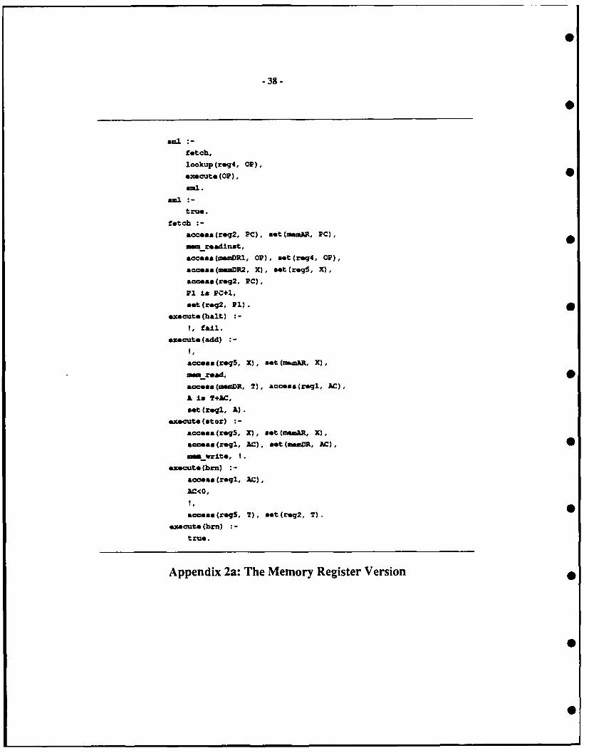
- 38-
fetch,
lookup(reg4, 0OP),
execute (01),
true.
fetch :
acceaa(reg2, PC), set(meaAR, PC),
Metmadinst,
accesz(namDRI, 01'), int(reg4, 01'),
accese(menDR2, X), saitcreg5, X),
access(reg2, PC),
P1 is Pc+l,
set(req2, P1).
execute(balt)
!, fail.
execute(add)
access(req5, X), set (maal, X),
access (vemDR, 2), access (regl, AC),
A is T+AC,
set(zeq., A).
execute(etor) :
acceas(reg5, X), aet (memAR, X),
a~a(regi, AC), act (wma, AC),0
MORwrite, 1 .
execute (br) :-
acceas(regi, AC),
AC(O,
access(reqS, T), zet(req2, T).0
execute (brn)-
true.
Appendix 2a: The Memory Register Version
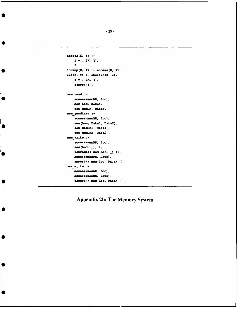
- 39 -
access(X, Y)
z -.. EX, Y],
Z.* lookup(X, Y) :-access(X, Y).
Bet(Z, Y) :-abolish(X, 1),
Z -.. [X, Y],
assert (Z).
=se read :
access (memAR, Lac),
mem(Loc, Data),
set (mmR, Data).
matreadinst :-
access (mAR. Lac),
mam(Lac. Datal, Data2),
set (in=RI, Datal),
set (auDR2, Data2).
ma write :-
access (msaR, Lac),
mac, J, ?,* ~retract(( mem(LeC,)))
access (manDR, Data),
assert(( mem(Loc, Data)).
matwrite :
access (msaiR, Lec),
access(m.DR, Data),* assert(( mem(Loa, Data)))
Appendix 2b: The Memory System

arcVar (req2, van).
aroVar (med=, var2) .
: rcVr (aakmDR2, var3)..rcVar(r~g2, van).
&roVan (reg5, war5).
*roVar (reqi. war7).*raVar (regs, vax9).
aroVar (Lvgi, vanlo).-
arcVar (roqi, varll).
arcVancregS, vanl2).
.xpVara (val,1, +, var4).
.xPVara (var6, var7, +, van).
exvvars (varfl, 0, < none).
dot Var (amiRvanl).
dotVar (n~q4, var2).
dat Van (roq5.var3).
datVan (req2, van4).
dat Van (=MM, vaz5) .
dat Van(regi, warS).dat Var(msmR, var9).dot Var (mioM, vanlO).
dst Van(re2, var32).
Appendix 3: Transfer Fragments
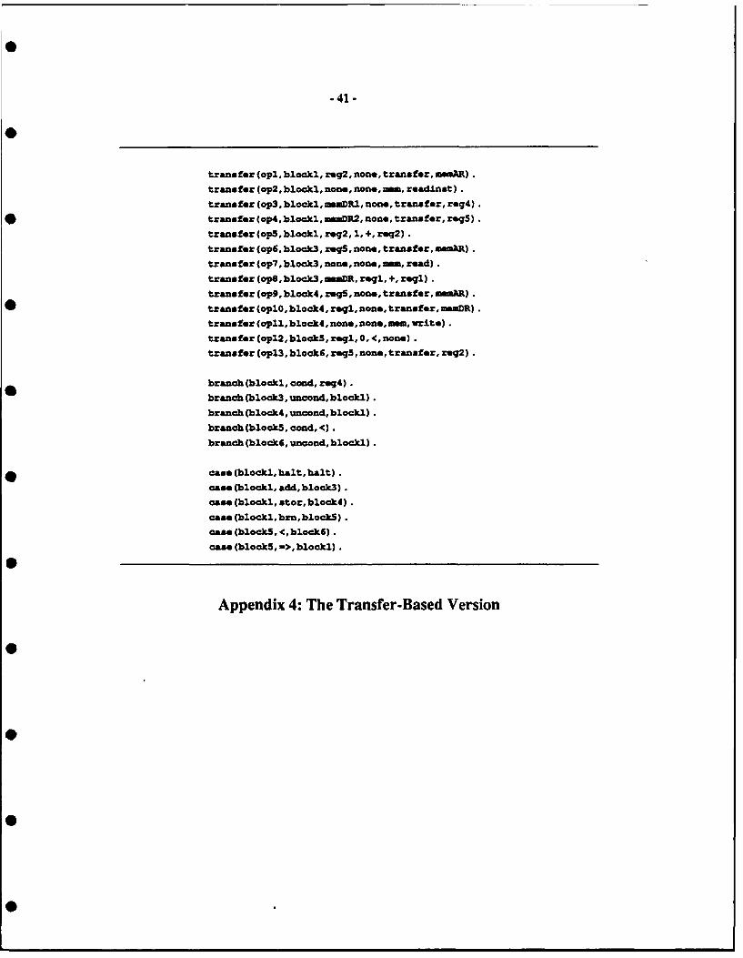
-41-
transfer (opl,blockl, reg2, non,transfer,amImR).
transfer (op2,blockl,none, non.,a, readinst).
transfer (op3, blocki,mDRI, zon., transfer, reg4).
* transfer (op4,blockl,maoDR2,nane,transfer, reg5).
transfer(op5,blockl,reg2,1,+,reg2).
transfur(ap6,block3, r=g5,non,tranfr,~m).transfer (op?, block3, none, none,ama, read).transfer (ope,block3,inaDR, reqi, +, reg).transfer (op9, black4, rinS, none,transfer, maR).
* ~transfer (oplO, block4, rei, noe, transfer,mizaDR).transfer (opl, black4, none, none,am, write).
transfer (opl2,block5,zr, , <, non.).trasfer (opl3, blockE, ringS,none, transfer, req2).
branch (blockl, cond, reg4).branch (block3, uncond, blocki).
branch (block4, uncond, blocki).
branch (blockS, ced, <).
branch (block6, uncond, blocki).
* case (blcckl, halt, halt).case (blocki, add, block3).case (blocki, stor,blcck4).case (blocki, bin,blackS).case (blockS, 4 blockE).case (blockS, ->, blockl).
Appendix 4: The Transfer-Based Version

-42 -
±oplioitDependent (m, .mAK).
±uplicitDependent (mnR, mm).implictDependent (meaDRi, mm).
impliitDepend-nt (MUR2, M- mm.
dependent (op5, opi. reg).
dependent (op2, opl, mm, =mAR) .dependent (op3. op2,mR1, mwm).
dependent (op4, op2,=ewR2 ,mm).dependent (op7, op6,mmum sAR).
dependent (op3 * op7, aemOR, mm).
dependent (opll, op9, am, moMA) .
Appendix 5: The Dependency Data Base 0
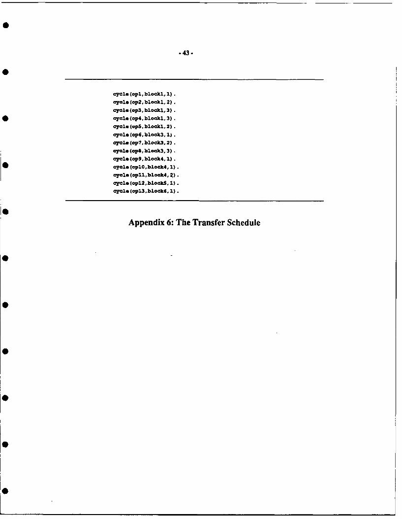
-43.
cycle (opl, blockl, 1).
cycle Cop2, blocki, 2).
cycle (op3 , blocki, 3).* cycle (op4,blockl, 3).
cycle (opS,blockl, 2).
cycle (op6,block3, 1).
cycle (op7. block3, 2).
cycle (ope,block3, 3).
cycle (op9Fblock4. 1).
* cycle (oplO,block4, 1).
cycle (opll~block4. 2).cycle (opl2,block5, 1).cycle (opl3,block6. 1).
Appendix 6: The Transfer Schedule

.44.
aement~yp. (reg2, e).elemantTyp. (aiuR, reg) .G1GeMentTYPe (uaM, aMaty) .oemtType (muDR, reg) .*limntype(req4,-ra).
ole.at~yp (roq5, reg).*ioemntTyp. (regi, re).eimntTyp. (addri, add.:).eiemnt~ype (buai, bus).
eiamnt~ype (bum2, bus).
elecoatType (bu. 3, bus).
eieamntft (mm, read) .aiemnti (e, write).*eemntln (adderi, add).eiemcntln(adderli c).
elemantUse (am,read, biocki, 2, ep2 ).elemegitfte (mem, read, block3, 2, op7 ) .elemtUse (e, write,bieck4, 2, api1).
elemantUse(reg2, arc, biocki, 1, pi).
eleamiltUse (meaR,dat,biocLI, 1, api).elietUse (mmDR, arc, biocki, 3, op3).
ciementUag (reg4, dat, biocki, 3, op3).
elemantgse (imDR, src,biockl, 3, op4).elementUse (reg,dst,blocki, 3, op4).
elementUse (adderi, inc,blockl, 2, op5).0
elematUse (reg2, sad, biecki,2, op5 ).
eleasatUse (rq5, ago, bock3,12, op6).
eimmntse (aemaR, dst,biock3, 1, apE).
elatUse (adderi, add, blockS, 3, opS).
eimatUae (in.DR, src,biack3, 3, apg).elementUae (regi, sad, block3, 3, op).
eilinentUse(reg5,arc,block4, i,op9).
eloeatUse (sM, dat,blook4, 1, ap9).
elamotUme (regi, arc, biock4, 1, oplO) .elementUse (amUR, dat,block4, 1, aplO).
eiemntUse(reg5,src,biack6, i,opl3).
eleamuntUse (reg2,dat,biock6, 1, api3).
elenmeatTest (sign, blackS, regi, reglsiqn, opi2).
eleantTest Cswitch, biacki, req4, reg4out, non.).
Appendix 7a: The Data Path Data Base -- Units

bu&Sra (busi, r~g2).
bu&Sra (bual, uemDR).
busSra (bu&2,mmDR).
* buxSro (bu*2, addrl).
buzSro (bmal, r~g5).
busSrc (bus2,ro~gl).
buzSra(bu*3, adderi).
busoat (bumi, moA).
* busDat (bual, req4).bunout (bu&2, r~g5).
buaDat (buzladdriporti).
buaDat (bu*2, reg2).
buaDat (buo2, addariport2).
buaDat (bu&3, reqi) .
*buaDat (bum2, mM
buaDat (bual, rog2).
busUas (bual, rmq2, mmAaR, biock, 1, api).
busUse(bua,ma",req4,biackl,3, op3).
buasa. (bu2,mDR, req5,blocki, 3, op4).
bu&Us.(bual, reg2, addriporti,biocki, 2, op5 ).
buzUse (buo2,-d ade, r"2 , bock, 2, opS).
busUme (bual, regS,ummAR, biook3, 1, apE).
ba*m. (busi, mOnR.addariporti, biock3, 3, opS).
busUm (bua2, rei, adderiport2, blook3, 3, opS).
* ~busUs.(bua3, adderi, rei, blook3, 3, opS).
busUm.(bual, r~g5,amUm,bock4, 1, op9).busUse(bu2,reqi,inuDR,biack4, 1, oplO).
busUm.(bumi, reS, r*g, biockE, 1, pi3).
0 Appendix 7b: The Data Path Data Base -- Buses
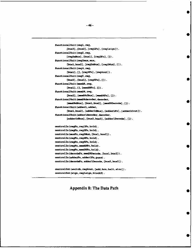
-46.
functionalflnit (regi, rog.
[bus3J, (buz2], treqlln], [zeglaigri]).
functJionalUnit (rog2, reg,[rmg2mu*u], (buslh, reg2Fu], ]).
functionalunit (req2u, Ix
Pbual,bu*2j * (reg2mBus] * (reqaNwc], (]).
funotionalUnit (req4, req.
Vbusl], C], (req4Fn], rq4outj).functionalunit (regs, req.
(bus2] *(bush], (reg5Un] * C).functionalUnit (mmR, req.
[busi], C], CmeuARrn], ]).functionalUnit (msDR, req,
(bus2], (~mRd~us], (mumDR~n], C]).functionalUnit (nmiDRdscoder, decoder,
[CamuDMdus], Cbusl,bus2],(mamDRDecode], ]).functionalUnIt (adderi, adder,
[busl,bus2], (adderldflus], laddrlln], CaddrlCout]).
functionalUnit (adderldecoder, decode:.
(addarldlus3, Cbus2,bus3], addziDecode], (3).
controln reqln, reqln,hold).
controlln (regft, reg2ft, hold).
controhln (muf, req2Mu,bush, bus2]).
controlln (r~qln, regln, hold).
controlln (zrn, req5lu,hold).
ontroln (vrn,mARia, hold).0
controlln (regin, wooDIn, hold) .
controln(decodein, ainDRDecode, (bush, bus2]).
controlln (adderin, adderlin, pass).
controlln (decodein, adderhoecode, (bus2, bus3]).
controlOut (switch, req~out, (add, brnuhalt, stor]).
controlOut (sign, reqlsign, blockS).
Appendix 8: The Data Path

-47.
%fetch
state CblocklCyclel,[output(aeaAP~n,dat), output(reg2Fn,src)],
* blccklCycle2).
state (blocklCycle2,
(output (adderlDecod., bum2), output (reg2Imx, bus2),
output (adderlln,inc), output (nieml, read), output (req2ft, sad)],
blocklCycle3).
state (blocklCycle3,
*6 (output (ammDDecode, busi), output (msmD1Decode, bua 2),
output (mmR~n, arc), output (req4Fn, dat), output (reg5vn, dat)],
awitch (reg4out,
[case (add, block3Cyclel), case (bin, block5Cyclel),
caxs(hait,haltCyc1*I) * cas(stor,block4Cyclel)D)).
P4add
state (block3Cyclel,
[output (asaI3Pn, dot) , output (reqSln, arc),
block3Cycl*2).
state (block~cycle2,
(output (mmft, read)],
* block3Cyc1e3).
state (block3Cyc1e3,(output (malDecods, busi), output (adderlDecode,bus3),
output (adderlan, add), output (m.DWn, arc), output (reqlfn, sad)],blockiCyclel).
%~ stor* state (block4Cyclel,
[output (mAeaa~n, dat) , output (==DMl, dat) ,
output (reqlln, arc), output (reg57n, arc)],
block4Cycl*2).
state (block4Cycl*2,
* blooklCyclel).
%brn
state (blocksWyclel, (]3switch (reqlaign,
(casim(gezero,blocklCyclel), caae(1tzero,block6Cycle1)])).
at ate (block6Cyclel,
(output (reg2M&i,bual), output (reg2Fn, dat), output (req5ln, arc)],
blockiCyclel).
* Appendix 9: The Control Path

.48-
oplnxapping(' +', add, arlog).
%memory
aignalValum (mafn, read, 1).
.ignalValu.(awarn, write, 3).
%rgister
aiqnalValue(reqin, arc, 0).
nignalValue(regrn, dot, 1).
signa.Walue(regft, sad. 1).
l±b(addr).
twOlorttyp. (adder)
signalvalum (addarin, add, 0).
signalValue(adderin, inc, 1).
%suign bit outputsignalValue(sign. gezoro, 0).
signalValue(aign, ltzero, 1).
Appendix 10a: The Functional Unit Library

-49.
r-q([Xn], (Out], (Load, Clock], _, Block)
build~leck (Refresh -aol (Load) ,8l),
build~lock (Masterm - transmit (Out, Load, Refresh) .32),
* build~lock (Masterm - transmit (Xn, Refresh, Load), B3),
build~lock (Masterout - aol (Mastermn),.3),
buld~iock (Slavein - pass (Masterout, Clock) ,35),
buildfllock (Out - aol (Slavea) ,B),
buildComposte~lock( [Bl,32,B3,34,BS,B6], Block).
* reg(Cln], (Out, Top], (Load, Clock], _, Block)
build[Block (Refresh -aol (Load) .31),
build~lock (Masterm - transmit (Omt,Load, Refresh) .32),
buildilock (Masterin transmit (n, Refresh, Load) ,33),
build~lock (Mastorout - aol (Mast srln),M3),
build~lock (Slaveln - pass (Nasterout, Clock) ,35),
* buildilock (Out - aol.(Slaveln) .36),
buildBlock (Top - aol (Slaveln) ,3),
buildComposite~lock( (31,32,B3,34,35,36,B7], Block).
decoder2 ( (nput], ( Outputl, Output2], (Control], _, Block)-
buildilock (not (Control) - aol (Control), 31),
0 build~lock (Outputl - transmit (Input. Control, not (Control)), B2),
buildilock (Output2 - transmit (Input, not (Control), Control), 33),
bulldCoupsiteBlock( (B1.32,33], Block).
auIx((Xnputl, Xnput2], [Output], (Control], _, Block)
* build~lock(CBar - aoi(not(Control)), 31),
buld~lock (Output-
aol(or( and(Inputl. MBar), and(Xnput2, Control) B) 2),
buildCompositeBlock( (31,32], Block).
adder(WA B], (Sum], Mina], (Cout], Block)
* buildBlock(X - aoi(or(and(Cln,or(1,B)) ,and(A,B))) .31),
build~lock(Y a aoi(or(and(X~or(A,B,Cin)),and(A,B,Cin))),32),
bulld~lock(Sum aoi(Y),B3),
bulld~loak(Cout -aoi(X),84),
buildCooslteBlock( (31,32,33,34], Block).
Appendix 10b: The Logic Equation Library

-0o-
plavaz(state(O)).
plavar(tate(2)).
plavar(stat. (3)).
plavazrgqt()).
plavar(roq4out (1)).
aUa (reg2MxO. adderlynO).
alias (muDpmccOds, rg4FnO).
alias (nwDRflcodO, zeg5FnO).
alias (add~rlecodeO *re93nO).
Appendix 11a: The PLA Equations -- Inputs and Aliases 0
0
0
0

pterm(statebleck3Cyclel, (izw(state(O)),state(l),inv(stata(2)),inv(state(3))]).
pterm(stateblock4Cyalel,Estat. (0), inv(state (1)), state (2) ,inv(state (3))]).
* pterm(statebloaklCyal.2, (izw(stat.(0)) ,inv(stat.(l)),inv(state(2)),
nv (stat. (3) )1).
ptezrm(stateblock3Cycle2, Eirw(state(0)),state(l),state(2) ,inv(state(3))]).
pteru(stateblocklcae3, (state(0),inv(state(l)),inv(state(2)),inv(state(3))]).
pterm(stateblock3Ccl.3, (state (0),state (1),*state (2), ±nv(state (3))]).
pterm(atateblock1Cyale3roq4outadd, jstate (0), ±nv(st ate(1) ),*mv (state (2)),
* inv(stat.(3)) ,roq4out(0),inv(reg4out(l))]).
pterm(statebloak1Cycl.3:.q4outbrn, (stat. (0), inv(state (1)), ±nv(state (2)),
inv(atate(3)),roqdout(0) ,reg4out (1)]).
pt.rm(stateblocklCycle3req4outhalt, Estate (0),*irw(state (2)) ,±iv(state (2)),
mLv (state (3) ) , ±z(rm4out (0)) , nv(reg4out (1) )])pterm(statbockCyole3rq4outtor, (state (0), inv(stat.(l)) , ±w(state (2)),
S 1nv(state(3)),±nv(req4out(O)),req4aut(l)]).
pterm(stateblock6Cclel, (izw(state (0)) ,state (1), inv(state (2)), stat.(3)]).
pterm(stateblock5Cyclelzoqlsiqnqezezo, (stat. (0),stat. (1) ,inv(state (2)),
inv(state (3)) , nv(r~qlsign(0))]).
pterm(stateblock4Cycle2, (state (0), ±nv(state(1) ) , nv(stat.(2)),state (3)]).
* ~~pteza (stateblock5Cyclelreglsignltzezo, (state (0) ,state (1) ,inv(state (2)),inv(&tate (3)) ,reglsign(0)]).
otera (state (0), (statebl.ock2Cyale2, stateblocklCycle3raq4outbrn,
stateblocklCyale3req4outstor, stateblock3Cycle2, *tateblook4CYclel]).
oterm (state (1), (stateblocklCyole3req4outadd, stateblockICycle3reg4outbrn,
* stateblock3Cclel, atateblock3Cycle2, stateblock5Cyolr~qlaiqnlt zero]).
oteza(state (2), (stateblocklCyale3rq4oathalt, stateblockICycl.3reg4outstor,
stateblock3Cclel, atateblook3Cycle2]).
otera tate (3), (stateblock3Cyole3, stateblock4Cycol, stateblock4Cycle2,
stateblock5Cyclelreqlsiqngezero, stateblock5Cyclelreglsignltzero,
stateblock~clel]).
* otera(aa.W1n0, (stateblooklCyclol, stateblock3Cyclel, stateblock4Cyclel]).
otera (reg23tz0, (stateblocklCycle2]).
otera (reg2lrno, stateblocklCyole2, stateblock6Ccyal]).
otera (saeuDDecodeO, EstateblocklCycle3]).
oter. (adderlDecodeO, (stateblock3Cco3]).
otera(meaDnnO, tstateblock4Cycl.1]).
Appendix Ilb: The PLA Equations.-- Product and Or Terms
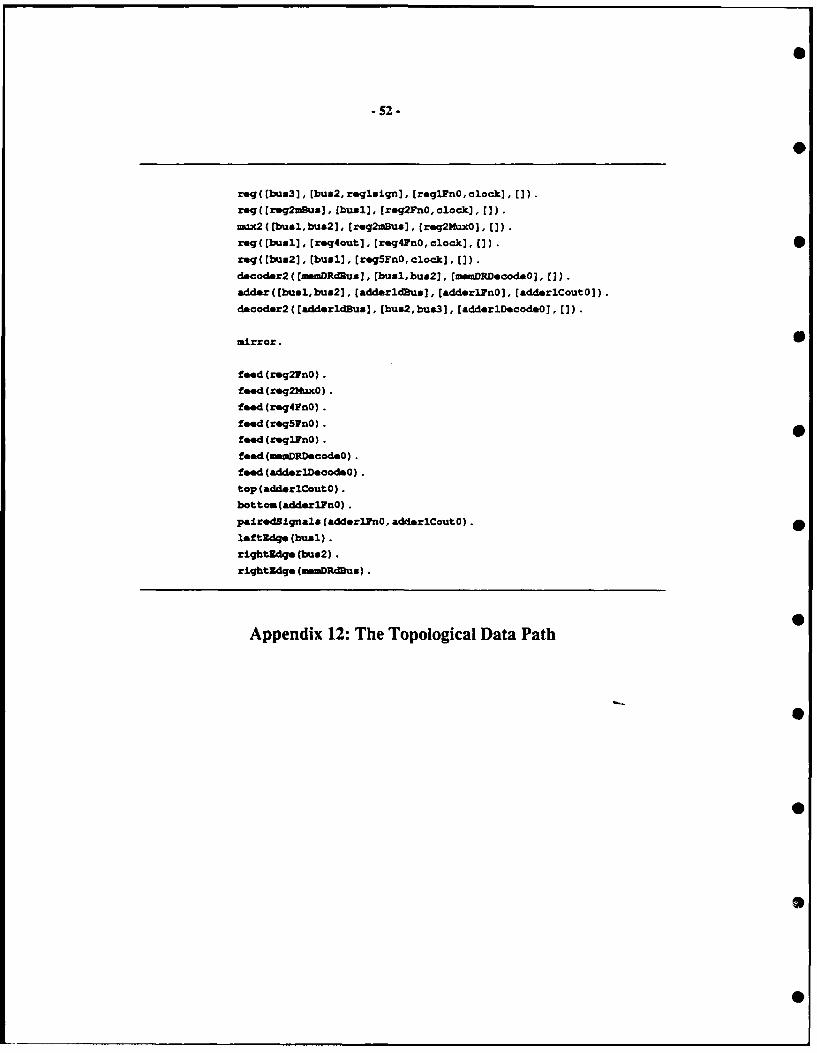
S52.
rzqgEbua3], bus2,roglsicqnJ.[reglFnO,clockJ, [J).req([reg2mBus], [bush, [reg2FnO,clock), [J).iuax2([bual,bus2J, (reg~mBus], (req2Hux0], U).reg([buuh]. Creg4out], Creq4FnO,clock], U).Sreg(fbus2], (busl], (reg5FnO,clock], []).dsaoder2((amDRdBua]. bual,bus2], (memDlDcod.O], (]).,Addr([buxl,bus2], [addrldus], (adderiFflO], (-AddrlCoutO]).
dmcoder2((adderldBus]. (bua2,bus3], [adderlDecodeO], []).
mirror.
food(rg~lnO).
f*"d(r~g2MxO) .
food (xsq4FnO) .
feed (req5FnO).
f**d(rghlnO).
feed (sD.Dscod.O).
feed(adderlDoodsO).
top (adderiCoutO).
botton(adds llnO) .
pairedsignala(adder2PnO, adderICoutO).
leftldq.(busl).
rightidge (bu&2).
rightidge (meDRdRus).
Appendix 12: The Topological Data Path

Js.Se .rkev.DU 16.01% Jobs clisplot Dotes set Sep 12 811231116 log?csfplo Wido 725 -30 16 397?S -- SC.1.1 O'mCrOn 1~£2 In~hou 1(n
- W.I, I. .-- .--- - ------
Appendix 13: The Sticks-Based Data Path Bit Slice
0
j5.Berkel*v.[DUbwh jobsI cilot Dotes Noss sep 14 foset6? Joey
cpOt. W ndol f 296%8 2;10 tt sScale: I WCi is IS.5 inches 4127K
0
Appendix 14: The Compacted Data Path Bit Slice
0
0

o.yPe.E.KUbdwh$J 3ob f gp10! t st S. 12 81,27: 1 M?,etf~ot*V~n.~ S5599 iSUBS -- Sel.;I slcven Is 5.51 InChev (ZSeX)
Apeni 15: The Co pate PLA
it i I 1111 1111 1 1
It I H i It
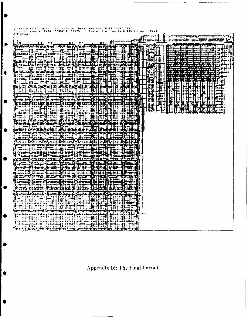
*!*y EDu g nol Jot:S ffolot Date: We *1 18,08:31:37 1997!ot , Co. .05 18's5 0 1 95975 --- Scale: I *-lcron 19 8 55 nce., ( lZ7x
f1-
11 __P
~~~~~~~~~~~~~: z _ _ _ _ _ _ _ _ _ _ _ __ _ _ _ _ _ _ _ _ _ _ _
0Z
# pedx1:TeFnlLyu
oil
NO

SECURITY CLASSIFICATION OF THIS PAGE
REPORT DOCUMENTATION PAGEla. REPORT SECURITY CLASSIFICATION lb. RESTRICTIVE MARKINGS
unclassified2a. SECURITY CLASSIFICATION AUTHORITY 3. DISTRIBUTION/AVAILABILITY OF REPORT
unlimited2b. DECLASSIFICATION/ DOWNGRADING SCHEDULE
4. PERFORMING ORGANIZATION REPORT NUMBER(S) S. MONITORING ORGANIZATION REPORT NUMBER(S)
Contract No. N00014-88-K-0579
6a. NAME OF PERFORMING ORGANIZATION 6b. OFFICE SYMBOL 7a. NAME OF MONITORING ORGANIZATIONThe Regents of the University (If applicable) Office of Naval Researchof California OfficeofNavalResearch
6c. ADDRESS (City, State, and ZIP Code) 7b. ADDRESS (City, State, and ZIP Code)
University of California 800 N. Quincy StreetBerkeley, CA 94720 Arlington, VA 22217-5000
Ba. NAME OF FUNDING/SPONSORING 8b. OFFICE SYMBOL 9. PROCUREMENT INSTRUMENT IDENTIFICATION NUMBERORGANIZATION (If applicable)
DARPA
8. ADDRESS (City, State, and ZIP Code) 10. SOURCE OF FUNDING NUMBERS1400 Wilson Blvd. PROGRAM PROJECT TASK WORK UNIT
Arlington, VA 22209 ELEMENT NO. NO. NO. ACCESSION NO.
11. TITLE (Include Security Classification)
A Prototype Silicon Compiler in Prolog
12. PERSONAL AUTHOR(S)William R. Bush, Gino Cheng, Patrick C.,ItGeer, and Alvin M. Despain
13a. TYPE OF REPORT 13b. TIME COVERED 114. DATE OF REPORT (Year, Month, Day) S. PAGE COUNTtechnical FROM0 7 /01/88TOI1I30!9C * December, 1988 ,
16. SUPPLEMENTARY NOTATION
17. COSATI CODES 18. SUBJECT TERMS (Continue on reverse if necezary and identify by block number)
FIELD GROUP SUB-GROUP
'9. ABSTRACT (Continue on reverse if nrecezary and identify by block number)
The Advanced Silicon Compiler in Prolog (ASP) is a full-range hardware synthesissystem based on Prolog. It produces VLSI masks from instruction set architecturespecifications written in Prolog. The system is composed of several hierarchicalcomponents that span behavioral, circuit, and geometric synthesis. This reportdescribes the prototype ASP system and its major components.
20. DISTRIBUTION /AVAILABILITY OF ABSTRACT 21. ABSTRACT SECURITY CLASSIFICATIONCOUNCASSIFIEDUNLIMITED C SAME AS RPT. 0 DTIC USERS unclassified
22a. NAME OF RESPONSIBLE INDIVIDUAL 22b. TELEPHONE (Include Area Code) 22c. OFFICE SYMBOL
DD FORM 1473, MsA 83 APR edition may be used until exhausted. SECURITY CLASSIFICATION OF THIS PAGEAll other editions are obsolete.