Embed Size (px)
Citation preview
A Proton Magnetic Field ControllerRichard Conley La Force, Gunilla La Force, and Christopher R. Hansen Citation: Review of Scientific Instruments 43, 1695 (1972); doi: 10.1063/1.1685526 View online: http://dx.doi.org/10.1063/1.1685526 View Table of Contents: http://scitation.aip.org/content/aip/journal/rsi/43/11?ver=pdfcov Published by the AIP Publishing Articles you may be interested in Shape of the proton in a uniform magnetic field AIP Conf. Proc. 1261, 135 (2010); 10.1063/1.3479331 Control of protontransfer reactions with external fields J. Chem. Phys. 98, 4548 (1993); 10.1063/1.465016 Measurement and Control of Magnetic Field Homogeneity Rev. Sci. Instrum. 39, 998 (1968); 10.1063/1.1683586 A ProtonControlled Magnetic Field Regulator Rev. Sci. Instrum. 19, 435 (1948); 10.1063/1.1741290 New transistor controlled by magnetic field Phys. Today
This article is copyrighted as indicated in the article. Reuse of AIP content is subject to the terms at: http://scitationnew.aip.org/termsconditions. Downloaded to IP:
131.94.16.10 On: Sun, 21 Dec 2014 18:38:34
THE REVIEW OF SCIENTIFIC INSTRUMENTS VOLUME 43. NUMBER 11 NOVEMBER 1972
A Proton Magnetic Field Controller
RICHARD CONLEY LA FORCE, GUNILLA LA FORCE, AND CHRISTOPHER R. HANSEN
Mayo Foundation, Rochester, Minnesota 55901
(Received 15 May 1972; and in final form, 19 June 1972)
We have designed, constructed, and operated a magnetic field controller that locks the field to a proton nuclear magnetic resonance signal. The frequency of the proton spectrometer is, in turn, locked to a frequency swept synthesizer. The controller operates over ±1000 Oe centered at 3000 Oe. The long term stability is 3X1Q-' Oe.
INTRODUCTION
A number of devices have been described that use the nuclear magnetic resonance signal from protons to either measure or control magnetic field.1- 6 The devices to control field frequently supply a supplementary error signal to an already extant field regulator.7os
We should like to report the design, construction, and operation of a magnetic field controller in which the magnetic field is locked directly to the signal from a proton resonance spectrometer. The spectrometer frequency is, in turn, locked to a crystal controlled, frequency swept synthesizer. This design has produced a field controller with long term stability, excellent linearity, and, because a marginal oscillator is used as the proton spectrometer, a sweep range of ± 1000 Oe about 3000 Oe.
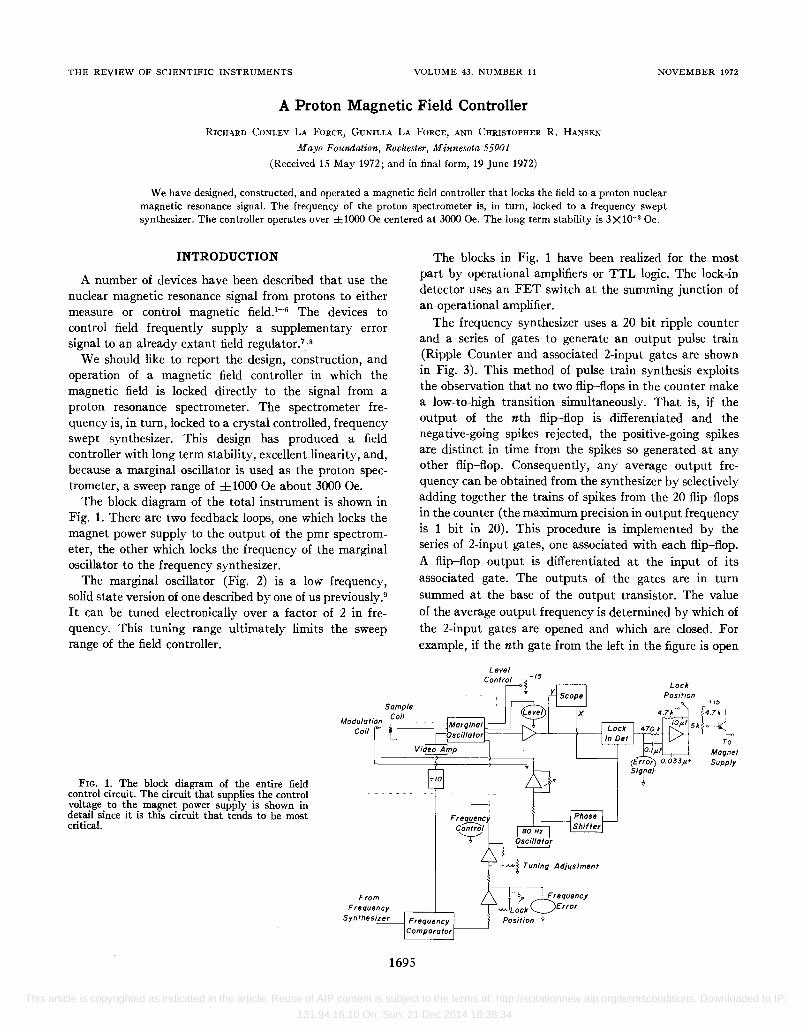
The block diagram of the total instrument is shown in Fig. 1. There are two feedback loops, one which locks the magnet power supply to the output of the pmr spectrometer, the other which locks the frequency of the marginal oscillator to the frequency synthesizer.
The marginal oscillator (Fig. 2) is a low frequency, solid state version of one described by one of us previously.9 It can be tuned electronically over a factor of 2 in frequency. This tuning range ultimately limits the sweep range of the field controller.
FIG. 1. The block diagram of the entire field control circuit. The circuit that supplies the control voltage to the magnet power supply is shown in detail since it is this circuit that tends to be most critical.
Coil
From
1695
The blocks in Fig. 1 have been realized for the most part by operational amplifiers or TTL logic. The lock-in detector uses an FET switch at the summing junction of an operational amplifier.
The frequency synthesizer uses a 20 bit ripple counter and a series of gates to generate an output pulse train (Ripple Counter and associated 2-input gates are shown in Fig. 3). This method of pulse train synthesis exploits the observation that no two flip-flops in the counter make a low-to-high transition simultaneously. That is, if the output of the nth flip-flop is differentiated and the negative-going spikes rejected, the positive-going spikes are distinct in time from the spikes so generated at any other flip-flop. Consequently, any average output frequency can be obtained from the synthesizer by selectively adding together the trains of spikes from the 20 flip-flops in the counter (the maximum precision in output frequency is 1 bit in 20). This procedure is implemented by the series of 2-input gates, one associated with each flip-flop. A flip-flop output is differentiated at the input of its associated gate. The outputs of the gates are in turn summed at the base of the output transistor. The value of the average output frequency is determined by which of the 2-input gates are opened and which are closed. For example, if the nth gate from the left in the figure is open
Level Control
Lock
Magnet Supply
This article is copyrighted as indicated in the article. Reuse of AIP content is subject to the terms at: http://scitationnew.aip.org/termsconditions. Downloaded to IP:
131.94.16.10 On: Sun, 21 Dec 2014 18:38:34

1696 LA FORCE, LA FORCE, AND HANSEN
100 k
10 Frequency Con Irol
10 Video Amp
100 p.hy
10 Level Meter
to Low Pass Audio Amp
and all other closed, the frequency of the output is tn times the frequency of the input. Similarly, if the gates are opened or closed according to a binary fraction with the most significant bit of the fraction associated with the left-most gate in the figure (1 opened, 0 closed), the average value cif the output frequency is just the fraction times the value of the input frequency.
The condition of the 2-input gates (opened or closed) is established by the output of another counter, the up-down counter in Fig. 3. The value of the binary fraction set into the gates can be controlled by toggling this counter, and, indeed, the value of this fraction can be swept continuously and uniformly to either larger or smaller values by applying a pulse train of some low frequency (~60 Hz) to the input of the counter and choosing to count either up or down.
Another binary counter (auxiliary counter) and an associated diode decoding matrix (the unlabeled counter
Oscil/alor
Ripple . .n Counler L1}
0.01
0.1
Panel Swilches
0.1 p.f
10 Level Conlrol
FIG. 2. A schematic diagram of the marginal oscillator. The transistor is either a 2N3819 or 2N3823. The voltage variable diodes are ITT BA163. The sample coil is about 40 turns of number 30 wire wound on a short length of plastic soda straw filled with water relaxed with ferric chloride.
and diode decQding matrix of Fig. 3) are used to establish both the initial setting of the frequency synthesizer, i.e., the initial value of the binary fraction, and its sweep range. The initial setting of the main up-down counter is accomplished by sending a train of ~4 HMz pulses into both the main and auxiliary counters. As the content of the auxiliary counter is decoded by the diode matrix it is reset, but the main counter is not. The diode matrix sequentially decodes binary fractions equal to one of the decimals 0.1, 0.01, 0.001, or 0.0001. How many times each fraction is decoded is selected by a panel switch (lower right-hand corner of Fig. 3). For example, in entering the fraction 0.1234, the diode matrix equai'to 0.1 is decoded once, then that for 0.01 twice, next the one for 0.001 three times, and finally the matrix for 0.0001 four times. Upon decoding 0.0001 for the fourth and last time the circuit terminates the entering procedure. The result of this
Decade Counter
FIG. 3. This circuit of the frequency synthesizer is not shown in complete detail because such detail would tend to obscure the principle. The circuitry that sweeps the value of the output frequency is not shown at all, but rather the synthesizer is shown as it is connected for entering a binary fraction into the up--down counter. The value of the binary fraction is chosen by the decimal counter and the four selector switches shown in the lower right-hand corner of the diagram. The crystal controlled oscillator runs at 4.2576 MHz.
This article is copyrighted as indicated in the article. Reuse of AIP content is subject to the terms at: http://scitationnew.aip.org/termsconditions. Downloaded to IP:
131.94.16.10 On: Sun, 21 Dec 2014 18:38:34

MAGNETIC FIELD CONTROLLER 1697
FIG. 4. This circuit makes the comparison of the frequency of the marginal oscillator (MO) with that of the frequency synthesizer (FS). The insert of error voltage vs frequency of MO indicates the ambiguous nature of the lock point. However, in practice only the interval where the error voltage passes from positive to negative is found and locked to.
MO
Error Voltage
entering procedure is to place in the main counter a binary fraction equal to 0.1234.
By choosing the input frequency to the 20 bit ripple counter to be 4.2576 MHz, i.e., lo of the proton resonance frequency at 10 000 Oe, the decimal fraction selected by the panel switch is equal to the field in Wb/m2 or, alternatively, in oersteds if multiplied by 1Q4.
Other parts of the decoding matrix together with the auxiliary counter are used to set the sweep range. For example, with the sweep range switch set to SO Oe, pulses at a low audio frequency (~60 Hz) into both the main and auxiliary counters advance the field until the diodes decode the auxiliary counter at SO Oe, then the circuit either turns off the pulse train or, if a triangluar sweep is desired, reverses the direction of counting.
Because the output of the frequency synthesizer (FS) is not a train of uniformly spaced pulses, a special circuit is necessary to compare its frequency with that of the marginal oscillator (MO) (Fig. 4). If the average frequencies of the FS and MO are identical, the contents of the two 16 bit counters will be identical at long times. When the content of the FS counter reaches 1 and 15 zeros, the content of the MO counter is entered into a latch which is connected to a digital-to-analog converter (DAC). If at this point the content of the MO counter is also equal to 1 and 15 zeros, there is no output from the DAC. However, if the frequency of the FS and that of the MO differ, an error signal is developed by the DAC which corrects the frequency of the MO. This error signal is in a sense not unique since only a 10 bit DAC is used to convert a 16 bit counter. But the error signal as a function of frequency (Fig. 4) changes sign only when the
Reset
Reset
MSB
L-__ IO_---'B:.../_·t--'.D_A_C_--.J~ Error Voltage to Frequency Control
two frequencies are identical. Our experience is that when the frequency control loop is closed, it is this interval that is always found and locked to.
The marginal oscillator, the level control circuit, the video amplifier, and the divide by 10 counter are all mounted in an aluminum box near the magnet. The sample (Fe+++ relaxed water) containing coil, and the modulation coil are rigidly attached to this box by an rf line made of parallel aluminum ground planes (3.81 X 40.6 cm) shielding two 1.59 mm diam brass rods on 1.27 cm centers. The over-all thickness of the line is 9.5 mm, i.e., it requires 9.5 mm of space in the magnet gap. The brass rods are the rf connections to the sample coil and are insulated from the shield by Lucite spacers. The current to the modulation coils is led in via an unshielded twisted pair. All signal and supply voltage connections are made between the MO box and control chasis via 3 m cables. This length is necessary because the magnet is on wheels to allow access to the sample region.
The frequency synthesizer has been built in one chassis while all other components including the monitoring oscilloscope and the frequency comparator are in another.
The usual regulator circuit in the magnet power supply (Brucker B-MNS 150/40) was bypassed and the control signalled directly to the pass transistors.
DISCUSSION
We have used this controller satisfactorily for two years in conj~nction with an electron spin resonance spectrometer for the study of nitroxide free radicals in biological membranes. The nitroxide signal consists of three lines
This article is copyrighted as indicated in the article. Reuse of AIP content is subject to the terms at: http://scitationnew.aip.org/termsconditions. Downloaded to IP:
131.94.16.10 On: Sun, 21 Dec 2014 18:38:34

1698 LA FORCE, LA FORCE, AND HANSEN
of width about 2 Oe and hyperfine splitting of 16 Oe. Spectra obtained several months apart are completely superimposable. Our estimate is that the long term stability (several hours) of the instrument is better than 3X 10⁻³ Oe, while the short term stability (2 sec time constant) is about 7X 10⁻³ Oe rms. These estimates were obtained by using a resonance line to convert field fluctuations into a noise tracing. We first noted the noise to be negligible off resonance. We then set the spectrometer to the center of a sharp line and from a knowledge of the rate of change of spectrometer output as a function of magnetic field at the line center converted the noise tracing to a field fluctuation.
Any or all detailed schematic drawings for the apparatus may be obtained from the authors.
ACKNOWLEDGMENT
We are pleased to acknowledge partial support of this work by the U. S. Public Health Service, National Institutes of Health, through Grant No. HE 13201.
1 R. J. Higgins and Yung Kwang Chang, Rev. Sci. lnstrum. 39, 522 (1968).
2 L. W. Rupp, Jr., Rev. Sci. lnstrum. 37, 1039 (1966). 3 August H. Maki and Richard J. Volpicelli, Rev. Sci. lnstrum.
36, 325 (1965). 4 W. L. Pierce and J. C. Hicks, Rev. Sci. lnstrum. 36, 202 (1965). 5 Yu-tung Yang and Yun-chao Chen, Rev. Sci. lnstrum. 37, 1274
(1966). 6 B. A. Coles, J. Phys. E 5, 287 (1972). 7 P. H. Foulger, J. S. M. Harvey, and R. H. Munnings, Rev. Sci.
lnstrum. 42, 92 (1971). 8 W. H. Wing, E. R. Carlson, and R. J. Blume, Rev. Sci. lnstrum.
41, 1393 (1970). 9 Richard Conley La Force, Rev. Sci. lnstrum. 32, 1387 (1961).
This article is copyrighted as indicated in the article. Reuse of AIP content is subject to the terms at: http://scitationnew.aip.org/termsconditions. Downloaded to IP:
131.94.16.10 On: Sun, 21 Dec 2014 18:38:34


![High spin rate magnetic controller for nanosatellites...Ovchinnikov et al. [24] have developed a controller that can also be implemented as a two-stage controller. The magnetic fault-tolerant](https://img.pdfslide.us/doc/110x75/5ec2a5ce4421bd21de53e7b2/high-spin-rate-magnetic-controller-for-nanosatellites-ovchinnikov-et-al-24.jpg)