Embed Size (px)
Citation preview

MP 03W0000157
MITRE PRODUCT
A Proposed Constraint Data Analysis Framework
August 2003
Catherine N. Bolczak Linda G. Cain Patricia A. Nussman
Sponsor: Federal Aviation Administration Contract No.: FTFA01-01C-00001 Dept. No.: F045 Project No.: 02033104-81
Approved for public release; distribution unlimited
©2003 The MITRE Corporation.
MITRE Center for Advanced Aviation System Development McLean, Virginia

THIS PAGE INTENTIONALLY LEFT BLANK

MP 03W0000157
MITRE PRODUCT
A Proposed Constraint Data Analysis Framework
August 2003
Catherine N. Bolczak Linda G. Cain Patricia A. Nussman
Approved for public release; distribution unlimited
©2003 The MITRE Corporation. All Rights Reserved. This is the copyright work of The MITRE Corporation and was produced for the U.S. Government under Contract Number DTFA01-01-C-00001 and is subject to Federal Aviation Administration Acquisition Management System Clause 3.5-13, Rights in Data-General, Alt. III and Alt. IV (October 1996). No other use other than that granted to the U.S. Government, under that Clause is authorized without the express written permission of The MITRE Corporation. For further information, please contact The MITRE Corporation, Contracts Office, 7515 Colshire Drive, McLean, VA 22102, (703) 983-6000.
The contents of this document reflect the views of the author and The MITRE Corporation and do not necessarily reflect the views of the Federal Aviation Administration (FAA) or the Department of Transportation (DOT). Neither the FAA nor the DOT makes any warranty or guarantee, expressed or implied, concerning the content or accuracy of these views.
MITRE Center for Advanced Aviation System Development McLean, Virginia

MITRE Department Approval:
Anthony G. Chambliss Program Manager TFM Decision Support System Evolution
MITRE Project Approval:
Frank L. Willingham Outcome Leader ATM Modernization

iii
Abstract
A Traffic Flow Management (TFM) framework for analyzing the operational use of and generating requirements for constraint data has been proposed. Constraint data requirements need to be generated in the context of TFM Modernization (TFM-M), TFM-En Route system engineering coordination via the Domain Integration Plan (DIP), and the future concept of System Wide Information Management (SWIM). The framework identifies a lifecycle for constraint data as it is used operationally, and includes key attributes and exchange needs that should be defined for an instance of constraint data. Initial examples of constraint data analysis and scenario development have been generated by the DIP activity. Further analysis and scenario development, along with requirements and cost/benefit analysis, will contribute to work packages. The work packages will be developed to identify the evolution and phasing of, and generate requirements for, new and integrated capabilities. This framework should be validated, either through formal review and feedback, or as part of the analysis and work package development process.
KEYWORDS: Traffic Flow Management (TFM), TFM Modernization (TFM-M), En Route Automation Modernization (ERAM), Domain Integration Plan (DIP), System Wide Information Management (SWIM), constraint data, adaptation data, work packages.

iv
THIS PAGE INTENTIONALLY LEFT BLANK

v
Acknowledgments
The authors wish to acknowledge the contributions of several persons to the development of this product.
The authors are appreciative of the thorough review and useful comments provided by Ronald Schwarz and Nels Broste of MITRE/CAASD.
We appreciate the diligence and thoroughness of Joan Arnold, Annette Warren Young, and Ellen Friedman of MITRE/CAASD in the preparation and production of this document.

vi
THIS PAGE INTENTIONALLY LEFT BLANK

vii
Table of Contents
Section Page
1. Introduction 1-1 1.1 Background 1-1 1.2 Related Initiatives 1-1 1.3 Timeframes 1-3 1.4 Document Organization 1-4
2. Framework Description 2-1 2.1 Definitions 2-1 2.2 TFM Operational Environment 2-2 2.3 Constraint States 2-3 2.4 Constraint Attributes 2-5 2.5 Scenarios 2-9
3. Framework Application 3-1
4. Constraint Data Catalog 4-1
5. Next Steps 5-1
List of References RE-1
Appendix A. Tools Associated with Constraint Information as Identified in the TFM Functional Audit A-1
Glossary GL-1

viii
List of Figures
Figure Page
1. Constraint Data States and the TFM Operational Environment 2-5
List of Tables
Table Page
2-1. Mapping of Constraint Types and States 2-4
2-2. Constraint Data Definition Attributes 2-6
2-3. Constraint Data Exchange Attributes 2-8
2-4. SWIM Requirements 2-9
3-1. High Level Data Exchange Needs, Domain Integration Plan (DIP) 3-2
3-2. Flight Planning Feedback CONOPS 3-5
4-1. Constraint Data Catalog 4-1
A-1. Tools to Monitor Constraints A-1

ix
Executive Summary
Traffic Flow Management’s (TFM’s) focus is to balance air traffic demand with system capacity to ensure the maximum efficient utilization of the National Airspace System (NAS) and available capacity. This balance is accomplished by anticipating the impact of demand and constraints on NAS resources’ capacity and then responding as needed with flow management initiatives. NAS constraints may be viewed as conditions that restrict or limit both the options for flight planning and execution as well as the options available for conducting TFM initiatives. Because of this, TFM is a major focal point for the consumption, processing, generation, and dissemination of constraint information to support NAS operations.
As TFM and other NAS systems are modernized and evolve to meet future concepts and requirements, there will be the need and opportunity for improving exchange of constraint information. To support this, analysis of the sources and uses of constraint information, in context of operational scenarios, need to be performed. Many of the analyses will be performed as part of extensibility work packages, which will be developed to identify the evolution and phasing of, and generate requirements for, new and integrated capabilities. Extensibility work packages are a mechanism intended to facilitate evolution of domain functional capabilities and architecture beyond the initial TFM-Modernization (TFM-M) baseline. These packages are intended to express domain operational needs and plans through the identification and description of strategic operational requirements. This document describes a framework that has been developed to facilitate the analysis of constraint information and requirements for its operational use.
Constraint data analysis and work packages will be developed in support of the following three initiatives:
• TFM Domain System Engineering and Integration. The TFM domain is undergoing continual change, with ongoing enhancements to the current Enhancement Traffic Management System (ETMS) and its associated systems. In addition, the TFM-M program will result in a reengineered ETMS baseline system that will be flexible, extensible, and will allow new functionality to be more easily incorporated.
• Cross-Domain Integration. There is a need to coordinate system engineering of interfaces, cross-domain functions, and common infrastructure (e.g., adaptation) components among the TFM, En Route and Terminal domains. The first formal effort in this regard is the TFM-En Route Domain Integration Plan (DIP), which began in Spring 2003, in conjunction with the TFM-M and En Route Automation Modernization (ERAM) programs. The DIP will identify opportunities for the

x
programs to influence their designs and requirements, so that they evolve to support better integration and possible sharing of common functionality.
• System Wide Information Management (SWIM). SWIM is a key component of the RTCA Concept of Operations (CONOPS) and the FAA Target System Description (FAA TSD). It is envisioned to provide operational data access, collection, storage, distribution, and integration services. While the SWIM concept has not yet been fully articulated, it is anticipated that service level requirements needed from SWIM, the allocation of functionality between TFM and SWIM, and directory/metadata will need to be defined for constraint data.
It is anticipated that many different organizations will be analyzing constraint information needs from varying perspectives. These include researchers developing concepts and prototyping new capabilities, system engineers generating requirements, and traffic managers and NAS users evaluating concepts and requirements. The framework was developed to facilitate commonality among and to ensure completeness of these efforts. To achieve this, the framework provides definitions of terminology; a description of how constraints are generated and changed over time, the key attributes that need to be captured for constraint information requirements and a description of scenarios to understand how constraint information is used operationally.
The framework comprises:
• Definitions of Terms. The terms “constraints,” “restrictions”, and “status” are frequently used interchangeably and have multiple meanings. The framework considers all of these as constraints and further subdivides constraints into the following categories: Conditions (e.g., weather), Responses to conditions (Restrictions and Initiatives), and Status (informational reports, frequently provided as common situational awareness).
• The TFM Operational Environment. The TFM operational environment as described in the TFM initial Requirements Document (iRD) lays out six major TFM task areas or functions. The task areas or functions include Common Situational Awareness; Flight Data Processing and Scheduling; Monitor Demand and Capacity; Problem Determination and Strategy Development; Strategy Execution and Exit Strategy; and Post Evaluation. The TFM operational environment provides a useful context for the analysis of constraints since the role of constraints varies based on the particular task area or function.
• Constraint States. A number of states describe a constraint’s certainty and operational impact over time. The states are: Static, referring to predefined constraints (e.g., Special Use Airspace (SUA)); Predicted, referring to potential activation of a static constraint or predicted event; Proposed, referring to a response

xi
or set of optional responses (restriction or initiative) that are candidates for addressing the predicted constraint; and Selected, referring to the response that has been implemented. All of the states have an associated definition, schedule, and eligibility. Predicted and Proposed states have an associated probability that they will occur. Selected states have an associated impact that tracks the degree of compliance with the initiative or restriction.
• Constraint Attributes. A comprehensive set of attributes is defined to completely describe an instance of a constraint and its operational use, thus enabling the explicit specification of unambiguous requirements. There are definitional attributes, including constraint identification and parameters such as affected resources, schedules, location, size and eligibility. Other attributes describe required data exchanges, including content, frequency, and participants. Finally, there are more future-oriented attributes that will help define SWIM service level requirements, such as registration, directory, metadata, and data exchange standards.
• Scenarios. Within the context of the TFM operational environment, scenarios provide a means to examine the operational use of constraint information. These scenarios include: background and motivation, assumptions, roles and responsibilities, key events, logical progression of steps and actions, implications, and issues.
The framework will be applied in a number of activities. The TFM-En Route DIP activity has initiated coordination of constraint information requirements, in conjunction with other related areas such as flight plan feedback, adaptation, and implementation of reroutes. In addition to continuing this coordination, next steps include development of work packages to support planning of enhancements beyond the baseline TFM-M capability. In some cases, constraint data analysis will be a part of a larger extensibility work package, such as constraint data supporting flight planning feedback. Others, however, may be more focused on a particular instance of constraint data, independent of its operational use, such as the acquisition of SUA status. These extensibility work packages and analyses will be prioritized in the near term to identify packages that need to be completed in time for the TFM-M JRC 2B decision in early 2005. This framework should be validated, either through formal review and feedback, or as part of the analysis and work package development process.

xii
THIS PAGE INTENTIONALLY LEFT BLANK

1-1
Section 1
Introduction
1.1 Background Traffic Flow Management’s (TFM’s) focus is to balance air traffic demand with system
capacity to ensure the maximum efficient utilization of the National Airspace System (NAS) and available capacity. This balance is accomplished by anticipating the impact of demand and constraints on NAS resources’ capacity and then responding as needed with flow management initiatives. NAS constraints may be viewed as conditions that restrict or limit both the options for flight planning and execution as well as the options available for conducting TFM initiatives. Because of this, TFM is a major focal point for the consumption, processing, generation, and dissemination of constraint information to support NAS operations.
As TFM and other NAS systems are modernized and evolve to meet future concepts and requirements, there will be the need and opportunity for improving exchange of constraint information. To support this, analysis of the types, sources and uses of constraint information, in context of operational scenarios, need to be performed. Many of the analyses will be performed as part of the development of TFM Modernization (TFM-M) extensibility work packages, which will be developed to identify the evolution and phasing of, and generate requirements for, new and integrated capabilities. Extensibility work packages are a mechanism intended to facilitate evolution of domain functional capabilities and architecture beyond the initial TFM-M baseline. These packages are intended to express domain operational needs and plans through the identification and description of strategic operational requirements. Work packages contain a summary statement of “the problem,” background information, and a scope description; and identify the potential activities, impacts, issues, interfaces and associated stakeholders. Work packages also include the cost/schedule/technical change and benefits information in response to the new work package requirement; and funding and schedule priorities.
A more detailed definition of extensibility work package content is a near-term activity outside the scope of this document. The purpose of this document is to provide context and a framework for the analysis of constraint information, which will lead to requirements for its operational use.
1.2 Related Initiatives There are several related initiatives which involve analysis of constraint data needs,
including the following:

1-2
TFM Domain System Engineering and Integration. The TFM domain is undergoing continual change, with ongoing enhancements to the current Enhancement Traffic Management System (ETMS) and its associated systems. In addition, the TFM-M program will result in a reengineered ETMS baseline system that will be flexible, extensible, and will allow new functionality to be more easily incorporated. Within the TFM domain itself, system engineering studies are needed to determine:
• Requirements for constraint data to support trajectory modeling. Currently, the ETMS trajectory modeler does not use altitude and speed restrictions in its algorithms. Some other Air Traffic Manager (ATM) automation systems process restriction data that has been codified and structured from text in Letters of Agreement (LOA) and Standard Operating Procedures (SOP), to generate trajectories that are more likely to match the route flown.
• Requirements for constraint data in predicting demand-capacity imbalances. Good predictions require accurate, up-to-date information about constraints, not just for TFM automation, but for NAS users as well. The automation can generate more accurate trajectories, thereby improving predictions of demand on NAS resources. For NAS users, awareness of constraints may influence their planning process, leading them to avoid constrained areas when they file flight plans.
• Requirements for recording and disseminating constraint data related to the planning and execution of TFM initiatives. In some instances this constraint information may be entered into a logging tool that is separate from the tool being used to plan and execute the initiative. It may be advantageous to provide integration between logging and decision support tools.
• Requirements for sharing constraint information with traffic managers, air traffic controllers, and NAS users. There are numerous methods and access points for different stakeholders to access and view constraint information. As the TFM infrastructure evolves there will be opportunities to provide integrated and more standardized views, where appropriate.
• Requirements for archiving constraint information for post analysis. There is a need to record and analyze, for system performance assessments, information about predicted constraints, what actually transpired, and resulting operational efficiency and equitability.
Cross-Domain Integration. There is a need to coordinate system engineering of interfaces, cross-domain functions, and common infrastructure (e.g., adaptation) among the TFM, En Route and Terminal domains. The first formal effort in this regard is the TFM-En Route Domain Integration Plan (DIP), which began in Spring 2003, in conjunction with the TFM-M and En Route Automation Modernization (ERAM) programs. The DIP will identify

1-3
opportunities for the programs to influence their designs and requirements, so that they evolve to support better integration and possible sharing of common functionality. The initial coordination is centered around adaptation, constraint data, flight plan preprocessing, and implementation of reroutes. A similar activity is planned for TFM-Terminal integration analysis.
System Wide Information Management (SWIM). SWIM is a key component of the RTCA CONOPS and the FAA Target System Description (FAA TSD). It is envisioned to provide operational data access, collection, storage, distribution, and integration services. Because the SWIM concept has not been fully developed, there are several open issues, including: the phasing of SWIM capabilities; SWIM’s role vis-à-vis Decision Support Systems (DSS) in providing value-added data services and custom processing; the extent to which SWIM will manage NAS data; the impact SWIM will have on future NAS architecture development and DSS structure and acquisition; and the extent to which SWIM will embody intelligence and trigger information flow based on changing status in the NAS.
While the SWIM concept has not yet been fully articulated, it is anticipated that service level requirements needed from SWIM, the allocation of functionality between TFM and SWIM, and directory/metadata will need to be defined for constraint data.
In all of the above contexts, the following questions need to be answered:
• What constraint data are used and how, for a particular task?
• Who and/or what systems need the information?
• How timely does the information have to be?
• What are sources of the information?
• What are the preferred or alternative sources of information?
• What is the needed granularity of the information?
• What operational changes need to or could be made?
• What automation changes are required, including functionality, processing, and interfaces?
1.3 Timeframes Three timeframes that are related to TFM and NAS evolution are chosen for the analysis.
Rather than using the RTCA CONOPS timeframes, the focus is on timeframes related to the modernization programs, their evolution beyond initial capability, and the instantiation of

1-4
future concepts for shared or common capabilities, such as common adaptation, kernels, SWIM, and Flight Object Management Service (FOMS).
Near-Term (Now-2007): During this timeframe, the TFM-M baseline capability, primarily a replacement of the ETMS functionality, is going to be designed and implemented. In addition, the first set of TFM-M enhancements will be defined, possibly to be deployed with the initial TFM-M build. Functional interfaces between TFM-M and ERAM will be defined as well, with the goal of influencing the designs of those programs where opportune.
Mid-Term (2007-2013): During this timeframe, TFM capabilities will evolve beyond the initial baseline capability, allowing for implementation of proven research capability, the integration of existing and/or new capabilities, and improved interoperability and integration between TFM and other domains.
Far-Term (2013-2020): During this timeframe, in addition to continued enhancements, the TFM infrastructure may undergo significant reengineering. Cross-cutting, integrated, and shared functions envisioned in the Target System Description (TSD), such as the FOMS and SWIM, will require major changes to and reallocation of functionality of domain-specific automation systems.
1.4 Document Organization This document is divided into five sections, including this first Introduction section,
which provides context and key timeframes for constraint information analysis. The analysis framework is defined in Section 2. Section 3 describes the application of the framework, using the initial DIP products as an example. Section 4 is a compilation of constraints that are potential candidates for study. Finally, next steps for analysis are described in Section 5. Appendix A provides a table from the Functional Audit Report of Existing Traffic Flow Management Infrastructure that lists key TFM tools used to monitor constraints.

2-1
Section 2
Framework Description
It is anticipated that many different organizations will be analyzing constraint information needs from varying perspectives. These include researchers developing concepts and prototyping new capabilities, system engineers generating requirements, and traffic managers and NAS users evaluating concepts and requirements. The framework was developed to facilitate commonality among and to ensure completeness of these efforts. To achieve this, the framework provides definitions of terminology; a description of how constraints are generated and changed over time, the key attributes that need to be captured for constraint information requirements, and a description of scenarios to understand how constraint information is used operationally.
2.1 Definitions The terms constraints, restrictions, and status are frequently used interchangeably and
have multiple meanings. In addition, a constraint can be not only the triggering event (e.g., weather) that essentially results in a demand-capacity imbalance, but the service provider response (e.g., a traffic management initiative) to mitigate an event as well. Operationally, all this information impacts or “constrains” the planning and execution of a route of flight or the alternatives for a future TFM initiative, and are in scope of this document. For simplicity, all of the following types of information can be referred to as “constraint” information, but understanding the key distinctions among them can help to clarify roles and responsibilities for managing the information.
Proposed term definitions are as follows:
• Conditions: Conditions are triggers, such as weather or closed airspace that may result in a service provider response. In general, the FAA cannot control constraints related to conditions. Examples are the activation of Special Activity Airspace (SAA) and prediction or occurrence of convective weather.
• Restriction, (as defined in the En Route-TFM DIP): Restrictions are imposed to manage traffic generally. The FAA can control constraints related to restrictions. Restrictions are responses to condition constraints (defined above). Examples include altitude and speed restrictions imposed at specified crossing points.
• Initiatives: Traffic Management initiatives are sometimes triggered by conditions such as the activation of military airspace or convective weather. An example is a TFM initiative such as Flow Constrained Areas (FCAs) and associated reroutes. The FAA can control constraints related to initiatives.

2-2
• Status Information: Frequently provided for common situational awareness, status information includes reports of conditions that may lead to preparation of one or more optional initiatives or restrictions, and reports of proposed or selected restrictions and initiatives. Status information is frequently provided for common situational awareness. Examples of status information are capacity drivers such as Airport Arrival Rates (AARs), Runway Visual Ranges (RVRs), runway configurations, outages; and status of constraints and restrictions (on/off, affected resources and flights).
For simplicity, all of these types of information can be referred to as “constraint” information, but understanding the key distinctions among them can help to clarify roles and responsibilities for managing the information.
2.2 TFM Operational Environment The TFM Operational Environment is described in the TFM initial Requirements
Document (iRD) Operational Concept, which reflects both current and future concepts. Constraint information plays a significant role in each of the operational environment’s six major operational functions or task areas described as follows:
• Common Situational Awareness. This is predicated on the need for operational decision making by NAS users and service providers to be based on common understanding of both the current and predicted states of the NAS.
• Flight Data Processing and Scheduling. Before filing their flight plans, NAS users’ flight planning systems interface with TFM systems to obtain available NAS status information. They can then submit intent flight plans to be evaluated for compliance with required syntax and constraints. As the TFM system updates information received from NAS users, the demand information is updated and shared as appropriate. Once NAS users confirm their flight plan is acceptable, they file it with Air Traffic Control (ATC).
• Monitor Demand and Capacity. This involves the continuous assessment of conditions and the prediction of demand/capacity imbalances that may lead to the need for imposition of an initiative.
• Problem Determination and Strategy Development. A strategy is a set of one or more proposed initiatives and includes a plan for when the participants will re-evaluate and determine if the planned initiatives should be implemented, modified, or terminated.
• Strategy Execution and Exit Strategy. Once a set of initiatives has been agreed to and implemented, it is disseminated to participants, and its effectiveness is monitored.

2-3
Based on the effectiveness of the initiative, the decision will be made to modify or terminate the initiative.
• Post Evaluation. Operational data are collected to evaluate what was predicted to occur, what initiatives were implemented to respond to predicted demand/capacity imbalances, what actually occurred, and the effectiveness of the initiative.
2.3 Constraint States One of the difficult aspects of describing a particular instance of constraint information is
that its certainty and operational impact change over time. To overcome this difficulty, four constraint “states” are proposed, as follows:
• State 1: Static. This state applies to constraint information that has static definitions of the NAS resource (i.e., airspace) impacted, schedule, and, where applicable, eligibility criteria to identify which flights would be impacted. Examples of such constraints include altitude and speed restrictions that are published in LOAs and SOPs, and SUA that is published in aeronautical databases such as NAS Resources (NASR). This information is available up to 56 days in advance of its use. While this information can be used for planning, it frequently is not in effect unless its status has been changed to “hot,” in the case of SUA, or “on,” in the case of an altitude or speed restriction. Not all constraint data has a “static” stage, such as Flow Evaluation Areas/Flow Constrained Areas (FEA/FCA), whose locations and impacted flights are defined on an ad-hoc basis, depending on the predicted location and movement of the condition.
• State 2: Predicted. This state applies to conditions. Predicted constraint information is triggered by an operational need to activate a static constraint due to congestion, or by identification of an external condition such as convective weather. The predicted constraint has an associated definition, schedule eligibility, and probability that it will occur. Once a constraint is predicted, traffic managers begin to develop alternative strategies to address the constraint.
• State 3: Proposed. This state applies to response (restriction or initiative) constraints that are proposed, possibly as options, for responding to a predicted constraint. Like a predicted constraint, a proposed constraint has an associated definition, schedule, eligibility, and probability that it will occur. When proposed constraint information is made available to stakeholders, they may alter their plans to avoid the constraint. In the future, “progressive planning” will allow decision-makers and automation to assess the combined impact of multiple constraints. These actions will impact the development of the plan, which will be an iterative process until it is selected. An example of a proposed constraint would be an FEA.

2-4
• State 4: Selected. This state applies to response (restriction or initiative) constraints that have been selected and are actively impacting flights. Examples are the implementation of a Miles-In-Trail (MIT) restriction, FCA and the associated reroutes, or the activation of a “static” restriction. In this case, “impact” as well as “eligibility” is relevant, as there may be exceptions to the application of a response, or non-compliance with it, that should be tracked. Such monitoring and assessment capabilities are planned for future implementation. In this stage, the effectiveness of the response would be evaluated, and equitability is tracked to minimize “double-penalties” for flights. If the response is not effective, or conditions change, the activated constraint may be modified or ended. Information is also collected for post analysis, and the effectiveness of the response may not be fully known until post analysis results are reviewed. If a response is found to be ineffective, it may be removed or modified as a static constraint.
Table 2-1 maps, for each constraint type, the relevant constraint states. Response (Restriction and Initiative) and Condition constraints can all have static/predefined states, although not in all instances. Only a Condition constraint has a predicted state. Response constraints have both proposed and selected states.
Table 2-1. Mapping of Constraint Types and States
Constraint State Constraint Type Static/Predefined Predicted Proposed Selected
Restriction Initiative Condition Status N/A – Reports the constraint state
Figure 2-1 shows how constraints progress through the four states, mapping them against the TFM Operational Environment. Constraints in all four states are relevant to Common Situational Awareness, Flight Data Processing and Scheduling, and Monitor Demand and Capacity. Predicted and Proposed constraints are relevant to Problem Determination and Strategy Development. Selected constraints are relevant to Strategy Execution and Exit Strategy, and to Post Analysis. Each state represents an incrementally decreasing time to assess and plan for impacts on flights. Static constraint information is available far in advance for planning purposes; however, in many cases, its uncertainty is relatively high. Predicted and proposed constraint information are available up to hours in advance, and together represent options for handling a constraint that is predicted to occur. Selected

2-5
constraint information represents an implemented constraint that has a certain impact on both flight planning and operations.
Static
•Definition•Schedule•Eligibility
Static
•Definition•Schedule•Eligibility
Proposed•Definition•Schedule•Eligibility
•Probability
Proposed•Definition•Schedule•Eligibility
•Probability
Selected•Definition•Schedule•Eligibility•Impact
Selected•Definition•Schedule•Eligibility•Impact
ExternalCondition
OperationalNeed Implement
Check forchanges inconditions &external plans
Monitor forEffectiveness,Equity, Compliance;Record forPost Analysis
Data ExchangesWho/What/When/How
Data ExchangesWho/What/When/How
Data ExchangesWho/What/When/How
Problem Determination& Strategy Development
Strategy Execution& Exit Strategy
Monitor Demand & Capacity
PostAnalysis
Common Situational Awareness
Flight Data Processing & Scheduling
Predicted•Definition•Schedule•Eligibility
•Probability
Predicted•Definition•Schedule•Eligibility
•Probability
Data ExchangesWho/What/When/How
Respond
Figure 2-1. Constraint Data States and the TFM Operational Environment
At each state, the analysis of constraint information needs to describe the required data exchanges, including who (traffic managers, controllers, NAS users, automation), what (constraint characteristics and status), when (once every 56 or 28 days, at a pre-determined time associated with a flight event, at pre-determined intervals, or whenever a modification is made), and how (email, telephone, message, display, website).
2.4 Constraint Attributes To completely describe an instance of a constraint and its operational use, a
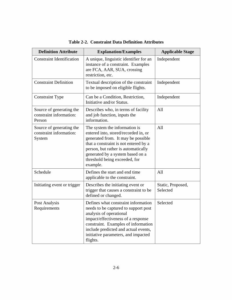
comprehensive set of attributes should be generated, so that unambiguous requirements can be explicitly specified. The attributes are both definitional, describing the constraint itself, and data exchange-related, describing the mechanisms and participants involved in the dissemination of constraint information. Definitional attributes are listed in Table 2-2. Data exchange attributes are listed in Table 2-3. In some cases, an attribute is independent of the lifecycle stage and thus does not change (such as a Constraint Identification). In other cases, an attribute may change, depending on the lifecycle stage. For example, the method or source of generating static constraint data may be different from the method or source of generating planned or active constraint data.
2-6
Table 2-2. Constraint Data Definition Attributes
Definition Attribute Explanation/Examples Applicable Stage Constraint Identification
A unique, linguistic identifier for an instance of a constraint. Examples are FCA, AAR, SUA, crossing restriction, etc.
Independent
Constraint Definition
Textual description of the constraint to be imposed on eligible flights.
Independent
Constraint Type Can be a Condition, Restriction, Initiative and/or Status.
Independent
Source of generating the constraint information: Person
Describes who, in terms of facility and job function, inputs the information.
All
Source of generating the constraint information: System
The system the information is entered into, stored/recorded in, or generated from. It may be possible that a constraint is not entered by a person, but rather is automatically generated by a system based on a threshold being exceeded, for example.
All
Schedule Defines the start and end time applicable to the constraint.
All
Initiating event or trigger Describes the initiating event or trigger that causes a constraint to be defined or changed.
Static, Proposed, Selected
Post Analysis Requirements
Defines what constraint information needs to be captured to support post analysis of operational impact/effectiveness of a response constraint. Examples of information include predicted and actual events, initiative parameters, and impacted flights.
Selected

2-7
Definition Attribute Explanation/Examples Applicable Stage Resource Involved Defines which NAS resource is
involved in the constraint. It may be an airspace volume, a route, fix, airport, or runway.
All
Probability of Constraint
The degree of confidence that a constraint will occur as predicted.
Predicted, Proposed
Eligibility
Rules for applying a constraint to a flight. Eligibility criteria may include the aircraft type, its origin and destination, and the route it is flying.
All
Impacted Flights Identification of the flights that were actually impacted by the constraint, regardless of eligibility.
Selected
Cause Description of the cause (condition) for the constraint’s imposition. Examples include severe weather, an equipment outage, a special event such as the Olympics, staffing shortages, etc. The cause will need to be associated with the response for common situational awareness and post analysis purposes.
Proposed, Selected
Volatility An indicator of the frequency with which the information changes.
Independent
Sensitivity An indicator of any associated privacy or security sensitivities that limit access to constraint data. Examples include VIP movements, security threats.
Independent

2-8
Table 2-3. Constraint Data Exchange Attributes
Information Exchanges Explanation/Examples Applicable Stage Content of Information Exchange
Describes what constraint information is exchanged. Examples include static descriptions of defined SUAs, on/off or hot/cold status, and initiative parameters.
Static, Planned, Active
Method(s) of information exchanged
Describes how constraint information is exchanged or disseminated. Examples include phone calls, web sites, automation displays or messages.
Static, Planned, Active
Frequency/Timeliness of Information Exchange
Describes how often the information exchange occurs. For static descriptions, it could be every 56 or 28 days. For more dynamic data, it may be for a defined interval (e.g., hourly), a predetermined time interval associated with an event (e.g., 45 minutes prior to flight filing); on demand; or whenever there is a change.
Static, Planned, Active
Participants in Information Exchange
Describes which people, facilities, and automation systems are involved in the information exchange. Examples include Traffic Management Specialists (TMSs), Traffic Management Coordinators (TMCs), Airline Operations Centers (AOCs), and specific automation systems.
Static, Planned, Active
Once the SWIM concept is more fully understood and its services are defined, there will be additional work packages involving the role of SWIM for constraint information. Requirements for SWIM services, such as constraint data access, collection, storage, distribution, and integration, will need to be developed. Functionality will need to be allocated between SWIM services and the TFM-managed automation and infrastructure. Table 2-4 lists some potential SWIM Requirements categories.

2-9
Table 2-4. SWIM Requirements
SWIM Requirements Explanation/Examples
Registration and Directory Services
Information needed for SWIM to locate and disseminate constraint data, including update rules, archive rules, publish/subscribe rules, etc.
Metadata Services Data about constraint data, to be registered with SWIM. This will allow the constraint data to be “discovered” by agents that are responsible for searching for and assimilating information in SWIM.
Data Exchange Standards Standards for data representation and format to facilitate SWIM data exchange (rather than point-to-point data exchange definitions).
2.5 Scenarios To better explain their operational relevance, constraint information concepts and
requirements can be expressed in the context of one or more related scenarios. Operational scenarios identify events that trigger constraints; describe how constraint information will be used; and determine the interactions between automation systems and humans. These operational scenarios can be used to clarify roles and responsibilities for managing constraint information, to assist in the development of research concepts and prototyping new capabilities, and to generate future system requirements.
The scenarios may be represented by written text, illustrative threads, storyboards, or other means. A proposed structure and content for the operational scenarios is described as follows:
• Name of the scenario: Descriptive identification of the scenario.
• Background:
− Motivation: rationale for writing the scenario.
States the specific purpose the scenario is to serve.
− Problem description: nature of problem that the scenario illustrates.
2-10
Explains what the topic is and why it is important to which stakeholders.
Characterize the stakeholders and their roles.
− How the problem is dealt with today.
Gives sufficient background to establish a starting point in the present.
− Environmental description: Location for the scenario.
• Introduction:
− Assumptions that the scenario makes.
Makes explicit values or objectives being assumed.
− Goal: how would we know that the problem has been resolved.
Scenario serves primarily to establish awareness of issues and relationships, of options for handling the issues, and of the implications of exercising the options.
The purpose of the Background and Introduction sections is to state the purpose of the scenario and to give enough background information that readers who are not well acquainted with the subject will have a reasonable starting point for understanding the scenario.
• Scenario: Text & Threads or other graphics.
− Roles and Responsibilities.
− Start and End Condition.
Describes relevant conditions in effect at the start of the scenario.
Describes end conditions toward which the events in the scenario are moving.
− Major Events.
Describes the circumstances leading to the events in the scenario.
− Steps/Actions.
Expresses the sequence of actions that make up the scenario.
Tells the story of one possible path into the future.
• Implications:
− Requirements.
Identifies areas of impact on requirements based on the scenario.
2-11
− Changes in assumptions.
− Benefits and drawbacks of the planned approach.
Draws attention to unexplored areas.
Identifies decision options and opportunities for improvement.
− Further scenario suggestions or special cases.
Indicates other broad paths the scenario might have followed under different assumptions.
• Issues: Questions that must be answered before requirements development/implementation.
− Highlights key issues.
− Illustrates arguments on differing sides of the issues.
− Identifies options available for addressing the issues.
− Projected impacts of different decisions/Consequences of exercising the options.

2-12
THIS PAGE INTENTIONALLY LEFT BLANK

3-1
Section 3
Framework Application
The TFM-En Route DIP activity, begun in Spring 2003, is intended to coordinate system engineering of interfaces, cross-domain functions, and common infrastructure between the TFM-M and ERAM programs. In the first several weeks, a plan was developed that identified the key Domain Integration Areas (DIAs) that need to be addressed by the DIP, as well as a proposed schedule of activities and products. The initial focus is on DIAs identified in an ERAM Requirements Issue Board (RIB) called “TFM-related Extensible Requirements,” which were Adaptation Data, Constraint Data Exchange, Trajectory Feedback, and Execution of Reroutes. Two of the DIP artifacts developed to support the RIB definition are provided in this section as examples of how the framework in Section 2 can be applied.
Table 3-1 describes constraint data exchange needs at a high level. The information was generated through working group discussions that included AT requirements representatives, and is intended to help with analysis of both trajectory feedback and flight plan filing and amendments via TFM. Although the table is preliminary information that needs further drill-down and expansion, it serves as an example of a structure for building requirements.
The table includes five columns. The first, Data Item, corresponds to the Constraint Identification Attribute of Table 2-1 and simply identifies the particular constraint instance. The second column, Restriction/Constraint, indicates whether the instance is generally applied for ATC purposes (a restriction), or applied due to an external event (a constraint). (This nomenclature was adopted for DIP, prior to development of the terms Condition, Restriction, Initiative, and Status in this framework. In the future, consideration should be given to the development of common semantics for constraint description and analysis across domains.) The Adapted? column indicates at what level in the ERAM adaptation scheme, a static constraint is defined, managed, and made visible. The What’s Adapted column indicates the information to be adapted. The fifth column, What’s Exchanged, corresponds to the Content of Information Exchange and Participants in Information Exchange attributes in Table 2-3.

3-2
Table 3-1. High Level Data Exchange Needs, Domain Integration Plan (DIP)
Data Item Restriction/Constraint
Adapted? What’s Adapted What’s Exchanged
Altitude, Speed Restriction
Restriction Yes, national
Crossing fix, lat/long, eligibility, schedule; eligibility includes: a/c type, origin, destination
En Route to TFM real-time: All adapted data (non-real-time) plus status as it changes (real-time, sent both ways between TFM and ERAM)
Arrival /Departure routes (Preferential Arrival Routes (PARs) Preferential Departure and Arrival Routes (PDARs), ATC Pref. Routes, route restrictions from LOA/SOP
Restriction Yes, distributed, nationally shared and managed locally
Route segments, eligibility criteria (a/c type, origin/destination, location or region
All adapted data (ERAM to TFM) and status changes (sent in both directions, potentially)

3-3
Data Item Restriction/Constraint
Adapted? What’s Adapted What’s Exchanged
Special Activity Airspace
Constraint Adapted, national (lateral confines); possibly online shared for vertical definition
Lateral shape; vertical strata if below 18, above 18 is real-time-defined ATCAA (ATC Assigned Airspace). Implementation should allow up to ten adapted rules (SAA eligibility rules), specifying the distance from the boundary or fix beyond which the aircraft is not subject to SAA restriction upon SAA activation (extensible); Also, should support alternate route adapted for each such “rule” (extensible)
All adaptation (non-real-time); real-time status (as it changes); real-time schedule periodically (how often, and how much); schedule, as it changes; adaptation sent from ERAM to TFM; all other data sent in both directions
Dynamic Real-Time Airspace Volumes (e.g. FCA or relinquished SAA bounds)
Constraint or restriction (pop-up)
Not adapted, created on the fly
Not adapted Shape (lateral and vertical); schedule, ownership, sent from ERAM to TFM
NAVAID outage
Constraint, or leads to a constraint
NAVAID location, perhaps scheduled outages
Location, scheduled maintenance
Outage time, duration; should be sent both ways between ERAM and TFM, maybe via a NIMS connection, ultimately

3-4
Data Item Restriction/Constraint
Adapted? What’s Adapted What’s Exchanged
Holding information
Restriction/constraint
No Not adapted Flight in hold, location of hold, time put in hold, Expected Further Clearance (EFC) time, time released from hold sent from ERAM-to-TFM.
The information in Table 3-1 is isolated from any operational scenario, which is needed to flesh out the triggering events, interactions between people and systems, the use of the constraint information, and other important aspects. Table 3-2, also generated via DIP activities, illustrates high-level scenarios describing a Flight Planning Feedback CONOPS. This table provides activity-specific information for phases of flight planning related to this time of flight departure. Like Table 3-1, more detail is required, but the table serves as an example of how operational scenarios can be described to round out the development of requirements.

Table 3-2. Flight Planning Feedback CONOPS
Activity/ Timeframe
Filed 180 days to
24 hrs
Proposed 24 hrs to ~45 min prior
to departure
Proposed < ~45 min prior to departure Substate: Clearance delivered
Active Post-departure
User Planning - Trial
Flight Plans are not retained. Evaluating potential routes against SAA weather, and restrictions.
Time-based parameter used in evaluation.
No retention of data.
Can be used to see if anything has changed since the last time the Flight Plan (FP) was filed.
Users get in addition to the basic trajectory feedback, business rules associated with the restriction (could be a mandatory reroute, could be an advisory).
Level of feedback can be user selectable.
User Planning - Intent
Flight plans are retained (by TFM) and used for demand/capacity predictions. User will be informed about constraint status changes via TFM systems. They may be subject to TFM initiatives based on their intent.
How far into this time window intent flight plans are accepted/allowed will be an adaptable value.
N/A
A Proposed C
onstraint Data A
nalysis Framew
ork
3-5

Activity/ Timeframe
Filed 180 days to
24 hrs
Proposed 24 hrs to ~45 min prior
to departure
Proposed < ~45 min prior to departure Substate: Clearance delivered
Active Post-departure
Filing Flight Plans are stored by En Route.
Intent flight plans may be automatically promoted to filed (or proposed depending on the time of the action), selectable by user. (TFM)
FPs may get rejected if the departure is within a time parameter and business rules (e.g. SAA is hot) applicable to the flight are violated. (En Route)
Feedback will depend on the timing: e.g. If 180 days prior to departure, feedback based on historic/nominal/schedule information. If closer to departure based on dynamic constraint status data. (TFM, En Route)
For filed flight plans En Route system will keep track of dynamic constraint status changes that invalidate the filed flight plan. Evaluation will be performed once 24 hr prior to departure (can be done by TFM), again in 45 minutes prior to departure (by En Route). Impacted flights will be identified and users will be provided feedback to replan and refile.
Reroute Execution
N/A Intent FP and filed FPs are subject to reroutes.
TFM will generate the change to the route after coordinating with users, provide it to En Route, 1) already filed, TFM provide instantly, 2) intent, TFM will apply change and go through the promotion process.
If the clearance is already delivered the pilot gets another clearance from the controller. Verbal coordination required between AOC, ATCSCC, TMU, Tower, and Pilot. Pilot puts the route into the FMS. TMU will amend the flight plan to be reflected in En Route system. Users can specify an alternate route if the reroute is not mandatory, and they have another preference.
Initial capability similar to AADR.
TFM provides a partial reroute based on the results received from trial planning and user negotiations. The reroute portion is marked, and will override application of ATC prefer routing which might alter the reroute. En Route receives the partial route representing the reroute, presents to the controller as a trial plan. Controller tailors the reroute and submits as an amendment after trial planning results are reviewed.
3-6
A Proposed C
onstraint Data A
nalysis Framew
ork

4-1
Section 4
Constraint Data Catalog
This section presents a compilation of constraint data that are potential candidates for study via inclusion in work packages. It is not an exhaustive listing, but should be the basis for developing the complete list. There are seven categories in the catalog:
• TFM Initiatives
• Airspace
• Oceanic Airspace
• Airport
• Outages
• Status
• Other
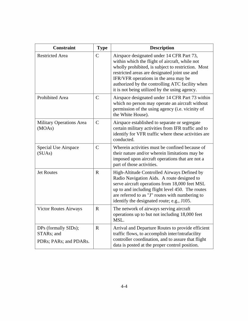
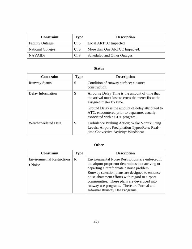
The catalog is listed in Table 4-1. Within a category, each constraint has associated information, including the Type (Condition, Restriction, Initiative, and/or Status) and Description.
Table 4-1. Constraint Data Catalog
TFM Initiatives
Constraint Type Description Projected Sector Capacity C Maximum Number of Aircraft which can
efficiently be managed by a Sector, given a set of conditions.
Projected Arrival Fix Capacity
C Maximum Number of Aircraft which can traverse an Arrival Fix within a time period given a set of conditions.
Flow Evaluation Area C/I Volume of Airspace being observed for possible future traffic congestion.

4-2
Constraint Type Description Flow Constrained Area (FCA)
C/I FCAs are airspaces defined by traffic managers to bound severe weather, congested airspace, or any other area of interest. Flights predicted to penetrate these airspaces can be easily identified and sorted for development of strategies to efficiently reduce flow through the constrained area.
Severe Weather Avoidance Program (SWAP)
I A formalized program implemented in areas particularly susceptible to severe weather. May consist of one or more of the following: expanded miles-in-trail, reroutes and GDP TMIs.
Miles-in-Trail (MIT) spacing restrictions
I A TMI limiting access to airspace at its boundary. One of a number of TFM techniques used to address En route sector congestion, resulting from unusually high demand or when available airspace is limited due to hazardous weather. MIT restrictions provide a means of: (1) reducing the overall average rate of air traffic flow over a fix or boundary, bound for a resource such as a sector or runway, (2) regularizing a flow, i.e., providing predictable, repeated spacing between successive flights, and (3) reducing the complexity of the air traffic that will be handled by each controller or controller team.
Ground Delay Program (GDP)
I A flexible TMI administered by the ATCSCC, holding aircraft on the ground to limit airborne holding. Use of a GDP results in arrival “slots” being rationed among airspace users, and flights assigned delayed departure times such that available arrival capacity will be efficiently used. Provides for the equitable assignment of delays to NAS system users.

4-3
Constraint Type Description Ground Stop I An immediate constraint used when an area,
ARTCC, sector or airport experiences a significant reduction in capacity. May be the result of weather, runway closures, major component failures, or other events rendering a facility unable to continue to provide air traffic services. May be total or partial.
Special Event Procedures C Special procedures established to accommodate abnormally large traffic demands at a location (i.e., Super Bowl, Kentucky Derby) or a significant reduction in airport capacity (airport construction) for an extended period.
Airspace
Constraint Type Description Fix Saturation S Scheduled A/C Exceeds Capacity to Transition
over Fix for a Specific Time Period Maximum Number of Aircraft which can traverse a Fix within a time period.
Fix Holding Information S Number of Aircraft Holding at a Specific Fix within a time period.
Suggested Airspace Configuration Changes
C (Future Concept): TFM recommends airspace configuration to ATC based on predicted constraints and their impact on traffic flows
Special Activity Airspace (SAA)
C Any airspace with defined dimensions within the National Airspace System wherein limitations may be imposed upon aircraft operations. This airspace may be restricted areas, prohibited areas, military operations areas, ATC assigned airspace, and any other designated airspace areas. Airspace Subject to Some Operating Restrictions
4-4
Constraint Type Description Restricted Area C Airspace designated under 14 CFR Part 73,
within which the flight of aircraft, while not wholly prohibited, is subject to restriction. Most restricted areas are designated joint use and IFR/VFR operations in the area may be authorized by the controlling ATC facility when it is not being utilized by the using agency.
Prohibited Area C Airspace designated under 14 CFR Part 73 within which no person may operate an aircraft without permission of the using agency (i.e. vicinity of the White House).
Military Operations Area (MOAs)
C Airspace established to separate or segregate certain military activities from IFR traffic and to identify for VFR traffic where these activities are conducted.
Special Use Airspace (SUAs)
C Wherein activities must be confined because of their nature and/or wherein limitations may be imposed upon aircraft operations that are not a part of those activities.
Jet Routes R High-Altitude Controlled Airways Defined by Radio Navigation Aids. A route designed to serve aircraft operations from 18,000 feet MSL up to and including flight level 450. The routes are referred to as "J" routes with numbering to identify the designated route; e.g., J105.
Victor Routes Airways R The network of airways serving aircraft operations up to but not including 18,000 feet MSL.
DPs (formally SIDs); STARs; and PDRs; PARs; and PDARs.
R Arrival and Departure Routes to provide efficient traffic flows, to accomplish inter/intrafacility controller coordination, and to assure that flight data is posted at the proper control position.

4-5
Constraint Type Description Military Training Routes R Airspace of defined vertical and lateral
dimensions established for the conduct of military flight training at airspeeds in excess of 250 knots Indicated Airspeed (IAS). These routes are used by the Department of Defense and associated Reserve and Air Guard units for the purpose of conducting low-altitude navigation and tactical training in both IFR and VFR weather conditions below 10,000 feet MSL.
Altitude Restrictions R An altitude or altitudes, stated in the order flown, which are to be maintained until reaching a specific point or time.
Speed Restrictions R A speed restriction can be applicable to published procedures of upcoming segments of a flight or applicable to 14 CFR Section 91.117. Also, speed restrictions can be specifically issued by ATC.
Dynamic Restrictions R Those restrictions imposed by the local facility on an "as needed" basis to manage unpredictable fluctuations in traffic demands.
Oceanic Airspace
Constraint Type Description Oceanic Routes R Oceanic organized Tracks and Routes are
established in international airspace and developed daily with consideration of winds aloft and other conditions.
Costal Fix R A navigation aid or intersection where an aircraft transitions between the domestic route structure and the oceanic route structure.
Oceanic Lateral and Vertical Separations
R Separation Intervals Using Nonradar Techniques.

4-6
Airport
Constraint Type Description Airport Status S An indication that there is a problem at a specific
Airport. For example, a runway that is unusable for aircraft operations.
Contaminated Runway C A runway is considered contaminated whenever standing water, ice, snow, slush, frost in any form, heavy rubber, or other substances are present.
Runway Configuration C Any runway or runways currently being used for takeoff or landing. When multiple runways are used, they are all considered active runways. In the metering sense, a selectable adapted item which specifies the landing runway configuration or direction of traffic flow.
Airport Acceptance Rate (AAR)
C A dynamic input parameter specifying the number of arriving aircraft which an airport or airspace can accept from the ARTCC per hour. The AAR is used to calculate the desired interval between successive arrival aircraft.
Airport Departure Rate (ADR)
C A dynamic parameter specifying the number of aircraft which can depart an airport and the airspace can accept per hour.

4-7
Constraint Type Description Airport Runway Visual Range (RVR)
C An instrumentally derived value, based on standard calibrations, that represents the horizontal distance a pilot will see down the runway from the approach end. It is based on the sighting of either high intensity runway lights or on the visual contrast of other targets whichever yields the greater visual range. RVR, in contrast to prevailing or runway visibility, is based on what a pilot in a moving aircraft should see looking down the runway. RVR is horizontal visual range, not slant visual range. It is based on the measurement of a transmissometer made near the touchdown point of the instrument runway and is reported in hundreds of feet. RVR is used in lieu of RVV and/or prevailing visibility in determining minimums for a particular runway.
Outages
Constraint Type Description Radars Outages C; S Radar outages can be the result of failure of the
ground radar equipment. The outage may also be attributed to the aircraft merging with weather or ground clutter, the aircraft operating below radar line of sight coverage, the aircraft entering an area of poor radar return, and a failure of the aircraft transponder.
Loss of Communications Equipment
C; S Scheduled and Other Communications Outages can cause the loss of the ability to communicate by radio. Aircraft are sometimes referred to as NORDO (No Radio). Standard pilot procedures are specified in 14 CFR Part 91. Radar controllers issue procedures for pilots to follow in the event of lost communications during a radar approach when weather reports indicate that an aircraft will likely encounter IFR weather conditions during the approach.
4-8
Constraint Type Description Facility Outages C; S Local ARTCC Impacted National Outages C; S More than One ARTCC Impacted. NAVAIDs C; S Scheduled and Other Outages
Status
Constraint Type Description Runway Status S Condition of runway surface; closure;
construction. Delay Information S Airborne Delay Time is the amount of time that
the arrival must lose to cross the meter fix at the assigned meter fix time. Ground Delay is the amount of delay attributed to ATC, encountered prior to departure, usually associated with a CDT program.
Weather-related Data S Turbulence Braking Action; Wake Vortex; Icing Levels; Airport Precipitation Types/Rate; Real-time Convective Activity; Windshear
Other
Constraint Type Description Environmental Restrictions • Noise
R Environmental Noise Restrictions are enforced if the airport proprietor determines that arriving or departing aircraft create a noise problem. Runway selection plans are designed to enhance noise abatement efforts with regard to airport communities. These plans are developed into runway use programs. There are Formal and Informal Runway Use Programs.

5-1
Section 5
Next Steps
The framework outlined in this paper is a proposal and should be validated. This may be accomplished through formal review and feedback, or as part of the analysis and work package development process, when the framework is exercised.
The TFM-M JRC 2B milestone is scheduled for February 2005. At that time, a decision will be made on whether to move forward with implementation of the modernized baseline design. In addition, the TFM Integrated Product Team (IPT) will be proposing an initial set of work packages for approval as enhancements to the initial TFM-M capability. In parallel, the DIP activity will continue the coordinated system engineering related to key ERAM and TFM-M intersections and commonality. Next steps include:
• Definition of the contents of an extensibility work package. Potential content includes operational concept/requirements; Functional Requirements; system-level requirements/modifications; interface definitions and requirements; design modifications; and benefit and cost estimates.
• Prioritization of extensibility work packages to be developed. The priority may hinge on the estimated difficulty or expense of implementation, the maturity of the concept, the degree of user interest, the dependencies requiring the implementation of one capability before another, the dependencies of complementary capabilities within TFM, En Route or other domains, and many other factors.
• Prioritization of constraint analysis to be executed. Some of the analysis will be a part of a larger work package, such as constraint data supporting flight planning feedback. Others however may be more focused on a particular instance of constraint data, independent of its operational use, such as the acquisition of SUA status.
Once the work packages and analysis have been prioritized, those that are near-term will need to be assigned to the appropriate organizations. Teams that can provide input to and evaluate the work packages will also need to be formed. CAASD will be developing a major work package or series of work packages related to TFM and En Route integration and interoperability. CAASD also will develop work packages for its research capabilities as they mature.

5-2
THIS PAGE INTENTIONALLY LEFT BLANK

RE-1
List of References
Bartkiewicz G. et. al, June 2003, Initial En Route Domain Extensibility Work Package Definitions, MTR 03W0000025, The MITRE Corporation, McLean, VA.
Broste, N. A., R. A. Schwarz, and R. N. Tarakan, July 2002, A Flight Restriction Data Service (FRDS) Description, MP 02W129, The MITRE Corporation, McLean, VA.
Computer Sciences Corporation Prepared for the Federal Aviation Administration, Working Version, August 2002, Functional Audit of Existing Traffic Flow Management (TFM) Infrastructure For The En Route Software Development and Support III (ERSDS III) Contract Task 12, Part 3.
Nolan, Michael S., 1990, Fundamentals of Air Traffic Control, Belmont, California, Wadsworth Publishing Company.
Department of Transportation, Federal Aviation Administration, July 2002, Air Traffic Control System Command Center Standard Operating Procedures, DCC 7200.100C.
Department of Transportation, Federal Aviation Administration, Draft En Route – TFM Domain Integration Plan, July 2003.
Department of Transportation, Federal Aviation Administration, November 2002, report of Existing Traffic Flow Management Infrastructure.
Department of Transportation, Federal Aviation Administration, May 2003, Initial Requirements Document For Traffic Flow Management Modernization.
RTCA SC 169, Operational Concept for Air Traffic Management (ATM) – Aeronautical Operational Control (AOC) Ground-Ground Information Exchange, 1997.
RTCA Incorporated, National Airspace System Concept of Operations and Vision for the Future of Aviation, 2002.
FAA Order F210.3, Facility Operation and Administration.

RE-2
THIS PAGE INTENTIONALLY LEFT BLANK

A-1
Appendix
Tools Associated with Constraint Information as Identified in the TFM Functional Audit
The “Functional Audit Report of Existing Traffic Flow Management Infrastructure – Final,” was developed by Computer Sciences Corporation for the FAA to support the TFM-M program. The report is a comprehensive compilation and description of the current TFM infrastructure, including facilities, service providers and users, interfaces, activities, automation tools and products. Exhibit 5-3 from that document lists tools that can be used to monitor constraints. The document also provides information about tools to be used to determine traffic demand, tools to be used for planning, setting up, and executing various TFM initiatives, and post-analysis tools.
Table A-1. Tools to Monitor Constraints
TFM Tool Functions For Monitoring Constraints
Reference to Functional Audit Tool Description
Traffic Situation Display (TSD)
Weather: Collaborative Convective Forecast Product (CCFP), weather overlays and weather requests (METARs / TAFs) Traffic
6.1.23
Display System Replacement (DSR) (if ARTCC) or ARTS Color Display (ACD)/Full Digital Alphanumeric Display (FDAD) (if TRACON)
Weather: WARP KDVT and DSR: Traffic KDVT: GI messages
6.4.3 (DSR) 6.4.1 (ACD) 6.4.5 (FDAD)
Flight Schedule Monitor (FSM)
Traffic demand and capacity values 6.1.14
Departure spacing Program (DSP) (if available)
Local departing traffic and capacity values, Apron/Gate Status
6.1.5

A-2
TFM Tool Functions For Monitoring Constraints
Reference to Functional Audit Tool Description
Traffic Management Advisor (TMA) or Center TRACON Automation System (CTAS) Terminal (if available)
Local arriving traffic and arrival fix capacity values
6.4.9 (TMA) 6.3.5 (CTAS Terminal)
Information Status tools (Information Distribution System [IDS]/System Atlanta Information Distribution System [SAIDS], Enhanced Status Information System [ESIS, Operations Information System [OIS])
Runway Configurations, Runway Status, Apron/Gate Status, NAVAIDS and other Equipment outages
6.3.4 (SAIDS) 6.1.7 (ESIS) 6.2.5 (OIS)
ATCSCC website Advisories, NAVAIDS and other Equipment outages
6.1.1
En Route Information Distribution System (ERIDS)
Runway Configurations, NOTAMs/CWA/MIS, Apron/Gate Status, NAVAIDS and other Equipment outages
6.4.12
National Traffic Management Log (TMLog)
Runway Configurations, Runway Status, Apron/Gate Status, NAVAIDS and other Equipment outages
6.1.21
Enhanced Traffic Management System (ETMS) Log
Runway Configurations, Runway Status, NAVAIDS and other Equipment outages
6.1.12
Runway Visual Range (RVR)
Runway Status 6.1.20

A-3
TFM Tool Functions For Monitoring Constraints
Reference to Functional Audit Tool Description
Other weather presentation systems (Weather and Radar Processor [WARP]/ Corridor Integrated Weather System [CIWS]/Terminal Doppler Weather Radar [TDWR]/ Integrated Terminal Weather System [ITWS]/Low-Level Windshear Alert System [LLWAS])
Integrated short term local current and forecast weather products
6.4.11 (WARP) 6.4.6 (ITWS)
“Functional Audit Report of Existing Traffic Flow Management Infrastructure”

A-4
THIS PAGE INTENTIONALLY LEFT BLANK

GL-1
Glossary
AADR Automated Assisted Dynamic Rerouting AAR Airport Acceptance Rate ACD ARTS Color Display ADR Airport Departure Rate ADU Application Data Unit AF Air Facility AOC Aeronautical Operational Control ARTCC Air Route Traffic Control Center ARU Air Traffic System Requirements/Air Traffic System Development AT Air Traffic ATC Air Traffic Control ATCAA ATC Assigned Airspace ATCSCC Air Traffic Control System Command Center ATCT Air Traffic Control Tower ATM Air Traffic Manager CAASD Center for Advanced Aviation System Development (MITRE) CCFP Collaborative Convective Forecast Product CIWS Corridor Integrated Weather System CONOPS Concept of Operations CTAS Traffic Management Advisor CWA Center Weather Advisory DIA Domain Integration Area DIP Domain Integration Plan DOTS Dynamic Ocean track System DP Departure Procedure DPR Daily Progress Report DPU Data Processing Unit

GL-2
DSP Departure Sequencing Program DSR Display System Replacement DSS Decision Support Systems EFC Expected Further Clearance Time ERAM En Route Automation Modernization ERIDS En Route Information Display System ERSDS En Route Software Development and Support ESIS Enhanced Status Information System ETMS Enhanced Traffic Management System FAA Federal Aviation Administration FAA TSD FAA Target System Description FCA Flow Constrained Areas FDAD Full Digital Alphanumeric Display System FEA Flow Evaluation Areas FEA/FCA Flow Evaluation Areas/Flow Constrained Area FMS Traffic Management Unit FOMS Flight Object Management Service FP Flight Plan FRDS Flight Restriction Data Service FSM Flight Schedule Monitor GI General Information GDP Ground Delay Program IDS Integrated Display System IPT Integrated Product Team iRD initial Requirements Document ITWS Integrated Terminal Weather System JRC Joint Resource Council KDVT Host Keyboard Video Display Terminal LLWAS Low-Level Windshear Alert System LOA Letters of Agreement

GL-3
METAR Meteorological Aviation Report MIS Meteorological Impact Statement MIT Miles-in-Trail MOA Military Operation Area MOAs Memorandum of Agreement NACO National Aeronautical Charting Office NASCAR National Association for Stock Car Auto Racing NAS National Airspace System NASR National Airspace System Resources NAVAID Navigational Aid NFDC National Flight Data Center NIMS NASA Infrastructure Monitoring System NOAA National Oceanic and Atmospheric Administration NOCC National Operations Control Center NORAD North American Air Defense Command NORDO No Radio NOS National Ocean Service NOTAM NOTice to AirMen OIS Operational Information System PAR Preferential Arrival Routes PDAR Preferential Departure and Arrival Routes PIReps Pilot Reports RIB Requirements Issue Board RTCA RTCA, Inc. (formerly Requirements & Technical Concepts for
Aviation; and formerly Radio Technical Commission for Aeronautics)RVR Runway Visual Range SAA Special Activity Airspace SAIDS Systems Atlanta Information Distribution System SIDs Standard Instrument Departure(s) SOP Standard Operating Procedures

GL-4
STARs Standard Terminal Arrival Route(s) SUA Special Use Airspace SWAP Severe Weather Avoidance Program SWIM System Wide Information Management TAF Terminal Area Forecast TDWR Terminal Doppler Weather Radar TFM Traffic Flow Management TFM-M Traffic Flow Management Modernization TMA Traffic Management Advisor TMC Traffic Management Coordinator TMLog Traffic Management Log TMS Traffic management Specialists TMU Traffic Management Unit TRACON Terminal Radar Approach Control Facility TSD Target System Description WARP Weather and Radar Processor

1