Embed Size (px)
Citation preview
A project of Volunteers in Asia
Low Cost Countrv Home Ruildinq
by: Technical Assistance Group, Department of Architecture, University of Sydney
., -Published by: Department of Environment and Planning 175 Liverpool Street Sydney, NSW Australia
Available from: Apace Rural Development Centre Federal via Lismore New South Wales 2480 Australia
Reproduction of this microfiche document in any form is subject to the same restrictions as those of the original document.
. .
DEPARTMENT OF ENVIRONMEINT & PLANNING
LOW COST COUNTRY HOME
BUILDING
A handbook on the essentia!s of Icw CC& ccnstruction for the guidance of rural homebuilders
Prepared by The Technicai Assistance Group, Department of Architecture, University of Sydney
Department of Environment and Phning 175 Liverpool Street, Sydney.
May 1981 80/60 ISSN 7240 4556 2
1
FOREWORD In December 1979 the former New South Wales Planning and Environment Commission or anised a seminar to discuss Hamlet Development in K ew South Wales at which the then Minister for Planning and Environment, Mr Paul Landa, anncinced that experimental building areas would be set u to test new building forms and materials for residentia P development and to give a broader understanding of building and health regulations to Councils, their staff, new settlers and all home owner-builders. This handbook, produced as a result of the Ex
r.3 erimental Building Area program, has been
pu lished, discussion.
not as a final document, but for public
I feel certain that it will help those with limited expertise in home building by rcvidin information which is not otherwise easily avar able on -P H cw cost materials and fcrms of construction. All the methods of construction and the materials described in the handbook are within the r’ramewcrk of the State’s building regulations. The Department of Environment and Planning would be pleased to receive comments and suggestions until 3; December 1982.
I ERIC BEDFORD Minister for Planning and Environment
3
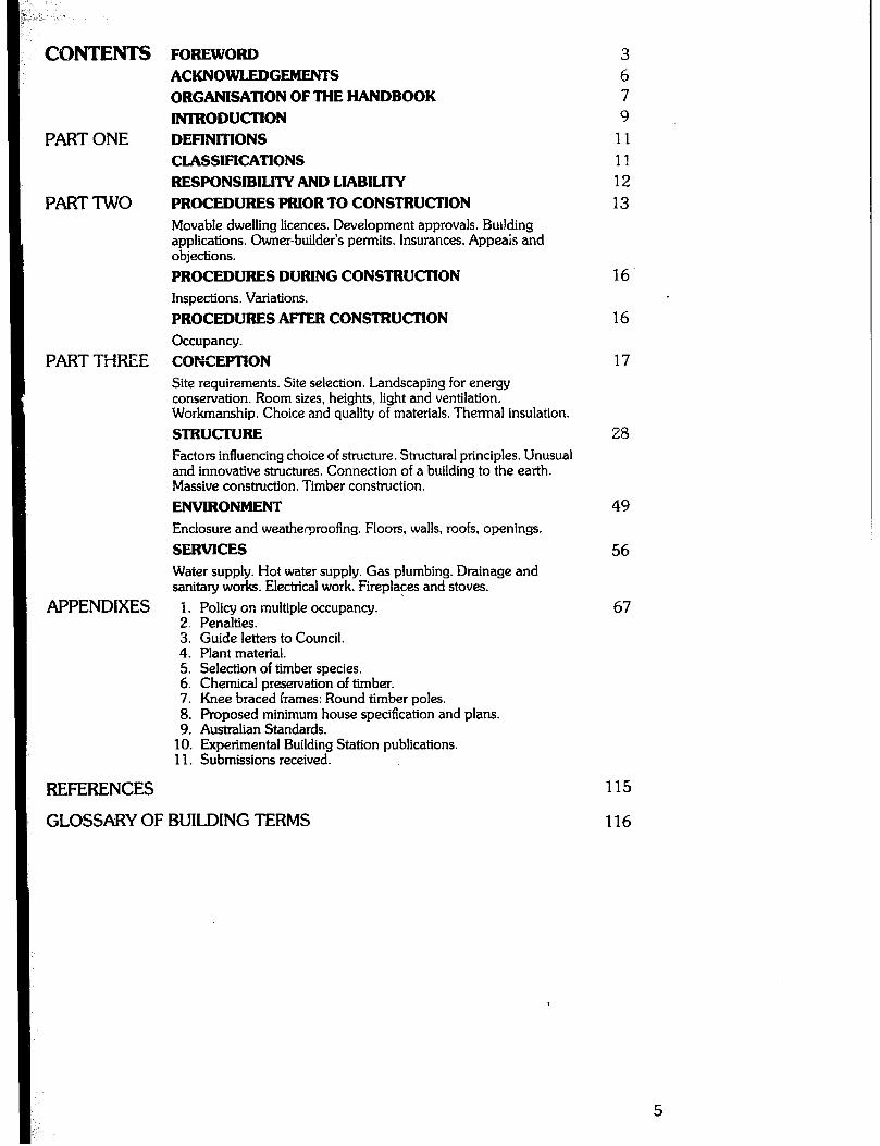
CONTENTS
PARTONE
PARTTWO
PARTTiiREE
APPENDIXES
FOREWORD ACKNOWLEDGEMENTS ORGANISATION OF THE HANDBOOK INTRODUCTION DEFINITIONS CLASSIFICATIONS RESPONSIBILITY AND LIABILITY PROCEDURES PRIOR TO CONSTRUCTION Movable dwelling licences. Development approvals. Building applications. Owner-builder’s permits. Insurances. Appeais and objections. PROCEDURES DURING CONSTRUCTION Inspections. Variations. PROCEDURES AFTER CONSTRUCTION occupancy. CONCEPTION Site requirements. Site selection. Landscaping for energy conservation. Room sizes, heights, light and ventilation. Workmanship. Choice and quality of materials. Thermal insulation. STRUCTURE Factors influencing choice of structure. Structural principles. Unusual and innovative structures. Connection of a building to the earth. Massive construction. Timber construction. ENVIRONMENT Enclosure and weatherproofing. Floors, walls, roofs, openings. SERVICES Water supply. Hot water supply. Gas plumbing. Drainage and sanitay works. Electrical work. Fireplaces and stoves. 1. Policy on multiple occupancy. 2. Penalties. 3. Guide letters to Council. 4. Plant material. 5. Selection of timber species. 6. Chemical preservation of timber. 7. Knee braced frames: Round timber poles. 8. Proposed minimum house specification and plans. 9. Australian Standards.
10. Experimental Building Station publications. 11. Submissions received.
3 6 7 9
11 11 12 13
16.
16
17
28
49
56
67
REFERENCES
GLOSSARYOFBUILDINGTERMS 116
115
5

ACKNOWLEDGEMENTS This handbook was prepared under the uidance of the Liaison Committee 1’~ the Experimenta Building Area 7
rogram E
nominated bt: the Minister for Planning and nvironment. The information contained herein does
not necessarily reflect the views of the organisations with whom they are identified.
LIAISON COMMITTEE MEMBERS Dr John Roseth Head, Research and Services Division, Department of Environment and Planning Mr Fergus Neilson Centrai Policy Division, Department of Environment and Planning Alderman W. G. Blair Mayor, Council for the City of L&more Mr Warwick Sherring Senior Building Inspector, Council for the City of Lismore Mr Ron Short Shire Health Surveyor, Principal Building Inspector and Town Planner, Bellingen Shire Council Mr John Lyons Health and Building Surveyor, Blacktown Council Mr Phil Ansoul Deputy Health and Building Surveyor, Parramatta Council Mr Paul Taylor Secretary, Australian Institute of Health Surveyors Mr John Armstrong I3;~;~y Chief Building Inspector, Builders Licensing
Mr John Frawley Senior Legal Officer, Builders Licensing Board Mr Ted Charker Chief Health Inspector, Health Commission of N.S.W. Mr Barry Sagar Principal Building Surveyor, Department of Local Government Mr E. J. Daly Building Advisory Officer, Department of Local Government Mr Frank Fotea Research Officer, Local Government and Shires Association MS Julie Walton Project officer, Local Government and Shires Association
6
‘This handbook was prepared by the Technical Assistance Group from the School of Architecture, University of Sydney, and nominated Research and Technical Assistants.
TECHNICAL ASSISTANCE GROUP MEMBERS Richard Aynsley BArch (Hans), MS (Arch Eng), PhD Patrick Healy, BE, DIC, MSc, MBA, MIE Aust. Graham Holland, BArch, ARAIA, ARIBA Coklinies, ASTC (Arch), MArch, ARAIA, DipT&CP,
Warren Julian, BSc, BE, MSc(Arch), DipBldgSc, MIES(Aust)
Brian Woodward
RESEARCH AND TECHNICAL ASSISTANTS Toni Appleton, co-editor Edwin Buivids, BArch(Hons) Jane Dillon, BScfArch), BArch(Hons) Denis Fulford, BEfHons) Peter Hamilton, BArch Nicholas Hello, BSclArch), BArch(Hons) Stephen Lesiuk, BArch(Hons) Helen Lochhead, BSc(Arch)Hons Daniel McNamara, BSc(Arch), BArch, co-editor Gary Mitchell, BSc(Arch), BArch Diane Moon, typist Stephen Stokes, BSc(Arch), BArch, co-editor John Watson, BA, DipEd Ian Gaillard, homebuilder David Gittus, homebuilder

ORGANISATION OF: THIS HANDBOOK This book is divided into four main parts, each out!ining the area of influence of the building regulations, or the ways in which that influence is exercised in relation to both the local council and the intending homebuilder. Part One deals with the preliminary assumptions and definitions from Ordinance 70 (the regulations concemin building in the N.S.W. Local Government Act 19197 confined to the essentials of domestic co&itructidn. It contains information on the classification of different building types, and gives a brief outline of the legal relationship between the local Council and the home builder, as regards their mutual responsibility and liability in the province of domestic construction. Part Two outlines the procedures used by local authorities to administer the Ordinance to homebuilders. This section has been further sub- divided into: 1) Procedures prior to construction. This explains the functions of movable dwellin building applications, owner %
, development and uilders’ permits,
insurances and the means of redress via appeals and objections. 2) Procedures during cons’u-uction. Inspections and variations to ensure the smooth execution of the job. 3) Procedures after construction, related to occupancy. Part Three describes how the Ordinance influences design and construction, and is intended as a guide to those wishing to carry out this work personally. In general, descriptions of buildin avoided, as these have been a i
techniques have been equately covered in
many other publications. However, where original material has been provided, and is not readily available elsewhere (for example siting and landsca energy conservation, and quantitative gui a
ing for es to earth
and round timber construction) these have been included. The principle underlyin
7 this section is that design is an
input into evey stage o a project, which becomes more and more concrete as steps are taken towards its realisation, from the initial considerations in the mind through the stages of drawings and model makin finally, the full-scale construction of the building.
, to, ?ll e
construction details are intimately tied to the overall design, and hence any particular aspect of the building should be considered in its context as part of a larger system, itself composed of smaller parts. Thus the following subsections have been loosely arranged to correspond with the steps normally taken in the realisation of a building pro’ect. However, it should not be taken to imply that, 1 or example, building services such as water supply or drainage are an afterthought that can be patched in to an almost completed building. It may be that it is possible for construction to proceed out of sequence, but bad plannin invariabl results in wasted time, wasted materi a? s, and dec ine in the overall job quality - Y factors which are as important to low cc ’ owner-built work as to the most sophisticated construction. Thus a
.?T of each subsection will assist the intending
d er to make design decisions based on some knowledge, and in accordance with the Ordinance. The first section is concerned with the initial considerations, such as siting, room planning, materials, and other resources.
Then follows a section on the structure of the building, those parts which go to make up the loadbearing skeleton, and the structural choices open to the intending builder. The third section concerns those principles of enclosure and weatherproofing, the makin of surfaces and openings so that the spaces of the bui ding are P suited to the lifestyle of the inhabitants. The fourth section outlines those common services which a homebuilder may wish to provide in the dwelling - hot and cold water supply, gas supply, drainage and waste disposal, electrical work and heating devices such as stoves and fireplaces. Part Four of the handbook, the Appendixes, provides detailed information on a number of matters treated more generally in the text. This handbook is intended to be read in con’unction with the works listed in the References, whit h will help to inform the homebuilder of the background to many of the principles outlined. Local building practice should further guide the homebuilder, as the intention of this handbook has not been to cover all materials and practices in use, but rather to outline the principles of building low cost, sound and environmentally responsible housing which reflects the values and aspirations of the inhabitants.
7

INTROtkJCTION The need for this handbook arose from the housing aspirations of new settlers in rural N.S.W., particularly within the North Coast region. An increased awareness of environmental values together with a desire to lead a simplified lifestyle has led to a re-evaluation of rural building practice. To meet these needs, many new settlers are building their own homes usin local materials and both simple and traditional % uildin methods. These techniques have been particular y P useful in providing emergency and vey low-cost accommodation. Under these circumstances it has been found necessary to provide improved information for aspiring home builders, particularly withregard to siting and building healthy and safe housing within the State building regulations. At the same time, information has been provided to guide Council building officers in their interpretation of the building ordinance to allow them to provide a more effective service to homebuilders. This has not been without difficulty. Homebuilders organisations have argued for less regulation and more personal responsibili
t , whereas Local Government
representatives have een pressing for more stringent standards interpretations to reduce their liability. It is hoped that this document will show how homebuilders could realise most of their aspirations within the scope of the regulations. At the same time, it may promote a better understandin between homebuilders and their Councils, where bo ill may co-operate to provide a healthy and safe environment for living. A work of this magnitude has on1 through the co-operative effort o Y
been possible
assistance provided b many people. The
and Plannin 7
(former y Planning and Environment Y the Department of Environment
Commission has been central to every aspect of the work, in
8 articular the settin
Liaison ommittee for the up and work of the
% erimental Buildin
ii rogramme, who supervised e preparation of iI
Area e
andbook in all its stages. This committee was widely representative of all Government bodies involved in health and buildin and was invaluable for the guidance given an % various regulations.
assistance with interpretation of the
A comglementay ro!e yxtlayed bLthe Home ullders Assoaation om the smore region who effectively represent new settlers. Their contribution as a group and as various contributors has provided the inspiration and stimulus to engage in such a task. Their submissions and counsel has ensured that the work will be of practical use to inexperienced people building their own home. The handbook was widely circulated in Government and Technical circles in a draft form prior to final editin elsew I!
. The submissions received are identified ere in the handbook and provided a vey useful
check as welI as new matetiaI for incorporation. The Technical Assistance Group from the Department of Architecture, University of Sydney, take responsibility for work in the handbook, and acknowled e the major role of numerous research assistants. %l e TAG. took advantage of man skilful and experienced homebuilders, architects an cy engineers from the North Coast region who provided a pxactid balance with advanced research workers and sophisticated resources from the University of Sydney. The Group is confident that within the terms of
reference working,within the scope of the existing building regulations that this handbook will rovide significant guidelines for Low Cost Country R ome Building in New South Wales. Colin James Sydney, 1981
9
I
PART ONE Part One contains definitions used in this handbook, most of which are selected from Ordinance 70 for their relevance to domestic construction. A wider list of terms appropriate to design and construction is contained in the Glossary, which is by no means exhaustive, but should help to clarify most sections of this handbook for the non-technical veader. Part One also contains information on the classification of building types likely to be used in rural areas for domestic construction. The final section of Part One is an opinion on the responsibility and liability of both Councils and homebuilders prepared by an eminent barrister experienced in N.S.W. Local Government law.
DEFINITIONS (see also the Glossary of Building Terms) ACT means the Local Government Act, 1919. AUSTRALIAN STANDARD means a publication, including an Australian Interim Standard, published by the Standards Association of Australia. BUILDERS LICENSING ACT means the Builders Licensing Act, 1971, as amended. COURT means the Land and Environment Court. DWELLING HOUSE means a building intended for use as a dwelling by members of a household. EXPANDED HOUSE means a group or cluster of buildings which together function as a dwellin
8 house
or Class I building. [An expanded house is N T a multiple occupancy, which is a group of dwelling houses, expanded or otherwise, on one allotment of land.] FOOTING means that part of the structure in immediate contact with the foundation, transferring the loads from the building to the foundation. FOUNDATION means the ground which supports the building. HABITABLE ROOM means a room (other than a bathroom, laundry, water closet, or the like) that is designed, constructed, or adapted for the activities normally associated with domestic living, and for this purpose - (al includes a bedroom, livin room, lounge room, music room, television room, kite 91 room, sewing room, study, pla
en, dining
the like; and (b) excludes in a oom, sunroom, and
CT dition to bathrooms, laundries, water closets, and the like, such rooms or spaces as food storage corridors, hallways, lob g
armies, walk-in wardrobes, ies,
clothes-drying rooms and o t?l hotographic darkrooms, er s
nature occupied neither frequen tr aces of a specialised
periods. y nor for extended
KITCHEN means a habitable room, alcove or other space provided for the pu cooking of food for the exe usive use of domestic living. T
ose of preparing and
LOADBEARING, applied to a wall, a part of a wall, a shaft, or any similar member, means intended to support a vertical load additional to its own weight. MASONRY means stone, brick, concrete block, or other similar building unit, or a combination thereof, assembled together unit by unit to form a wall, pier, chiiney, or other part of a building.
MEZZANINE means a space within a room which is not fully enclosed nor encloses the space below it and is situated between - “(a) an intermediate floor constructed within a room, and (b) the floor level, ceiling or roof above, as the case may be; and in which the intermediate floor does not extend across the full area of the room.” (ORDINANCE 70) (This definition is under review by the Local Government Department) MOVABLE DWELLING means any tent, van, or other conveyance whether on wheels or not, and any shed or similar structure or conveyance which is used either regularly or intermittently for human habitation. MULT1PL.E OCCUPANCY, for the pu oses of this handbook, means a group or groups o ‘p Class I and Class X buildings on one allotment of land, and does not include any Class II or Class III buildings. ORDINANCE means Ordinance 70, 1972, under the Local Government Act, 1919. OWNER, in relation to land, includes every person who, jointly or severally, whether at law or in equity - (a) is entitled to an estate of freehold in possession in the land; (1)) where the land is Crown lands under a prescribed tenure, is entitled to any prescribed estate or interest in the land as prescribed by the Building Licensing Re lations; (cl where the land is not Crown lands, is enti tY ed to any prescribed estate or interest in the land as prescribed by the Building Licensing Regulations. OWNER-BUILDER, in relation to any building work, means a person who carries out that buildin work pursuant to an owner-builder’s permit, issue cp under the Builders Licensing Act, 1979. yyIJ2LIC HEALTH ACT means the Public Health Act,
STRUCTURAL MEMBER means a part of the structure of a building, and includes a footing, column, pier, wall,
P arapet, partition wall, shaft, floor, roof, ceiling, stair,
anding, ramp, or balcony, and any supporting part incorporated therewith.
CLASSIFICATIONS It is important to establish clearly the classification of any building, as some provisions of the Ordinance apply to certain classes of buildings and not to others. The following classifications of buildings are found in the Ordinance: (a) Class I: Single dweliing-houses. (b) Class II: Buildings containing two or more flats.
11
(c) Class III: Residential buildings, being common places of zL ,qde for a numbsr of unrelated persons, including -
(i) boarding houses, guesr houses, hostels, and lodging houses; (ii) the residential portion of hotels and motels; (iii) the residential portions of schools; (iv) the residential portions of institutional buildings accommodating members of the staff of the institution; and (v) flats not included in paragraph (b).
(d) Class X: Outbuildings. These may include greenhouses, conservatory, summer-house, boat- house, fuel shed, tool-house, aviary, milking-bail, hay shed, stable, fowl-house, pigsty barn or the like.
0 IL1 DL IL1 Section 311 of the Local Government Act provides that a building shall not be erected or altered unless the approval of the local Council is obtained beforehand. This is the responsibility of the homebuilder. Part Two of the handbook sets out the relevani procedures. Apart from statutory responsibilities, an owner of a building has a general common law responsibility in relation to buildin work. The work must be undertaken carefu ly, 9 with due regard to the safety of the future occupants of the building and the interests of owners and occupiers of other properties in the nei hbourhood. This does not preclude low cost bui din H
% and the use of second-hand materials. It does
mean t at care should be taken to ensure that appropriate, sound materials are chosen and that proper building techniques are used. The advice set out in Part Three should materially assist homebuilders in meeting those requirements. However, no book can foresee all problems. If the homebuilder is in doubt, in relation to any matter which might involve the safety of persons or property, he should obtain advice on the problem from a suitably experienced person. The Local Government Act places upon Councils the responsibility of ensuring that buildings erected within their areas are erected in accordance with ordinance requirements. Under some circumstances, Councils (and their officers) ma be held liable to pay damages to persons who suffer oss or dama Y
B e as a result of a
neglect of that du absolute one; the 2
. The responsibi ity is not an ouncil must be shown to have failed
to take reasonable care in some material respect e.g. consideration of the building plans, inspection of the site or of foundations. Council’s responsibility is well understood. It applies to all buildin s. In is no reason why new or additiona s P
rinciple there prob ems should
arise out of the increasing popularity of low cost country home building. Perhaps, however, there have been practical difficulties; building inspectors, inexperienced in this type of construction, may have felt uncertain as to appropriately acceptable standards. This handbook attempts to specify those standards. Generak speaking, adherence to the requirements of the han cy book should obviate any legal difficulties for both builder and Council.
Murray Wilcox Q.C.
12

PART TWO Part Two outlines the procedures by which the Local Government Act and Ordinance 70 interact with the homebuilder. These procedures take the form of applications, permits and approval; which must be sought from Local Councils or other authorities, and the avenues of appeal by homebuilders against the decisions of those bodies. Part Two has been subdivided according to the place that these procedures occupy in relation to the construction process, namely:
Procedures prior to comstruction: - Movable Dwelling licenses for shelter prior to and during construction. - Development Ap land use is in actor cr
roval to ensure that the proposed ante with local zoning and
planning regulations. - Building Application showing details of intended building/s. - Owner-builder’s permits - Insurances - Appeals against the decisions of Councils or other bodies on any of these matters.
Procedures durin construction: - Inspections made by 35 during building.
ouncil officers at stages
- Variation procedures for altering or amending Building Applications to accord with changes desired by the homebuilder.
Procedures after construction : - Occupancy approval at an appropriate later stage in construction.
PROCEDURES PRIOR TO CONSTRUCTION Movable dwellings Persons wishing to camp on land, either temporarily or while building a permanent dwelling, should the Council for a Movable Dwelling Iicence.
a ply to WR ere
such an application has been made to the Council ‘L . . . the council shall be deemed to have unconditional1
Y , unless, within four weeks r
nted it om the
receipt there0 , the council or its authorized servant gives notice to the applicant stating that his application is refused, or stating the conditions subject to which the licence is granted” (Section 288A(6) of the Act). Some Councils have application forms for Movable Dwellin licences. If not, homebuilders may use the form of etter included here as a guide for an 8 application for a licence. The Council may, within the period stated above, im ose conditions such as a fee and/or a period for the icence, after which extensions P as necessary should be sought. Under Section 288A(7) of the Act, a Movable Dwelling licence is not required for a movable dwelling which: (a) is kept by its owner on land occupied by him in connection with his dwelling house and is used for habitation only by him or by members of his household; or (b) is kept by its owner on pastoral or agricultural land
occupied by him and is used for habitation only in certain seasons and only by persons employed in pastoral or farming operations on that land, In all other cases a license is necessary. See Appendix 3 for guide letter to Council.
Development Applications The following situations may arise where it is necessary to obtain Council’s consent to .ri72 proposed use of land (Development Approval): (a) Where it is proposed to build a single dwelling on an allotment which is less than the required area for its zoning; (b) where it is proposed to build in an area of high landscape significance; (cl where it is proposed to build more than one dwelling on an allotment that is, a “multiple occupancy”; (d) where it is proposed to build extra dwellings on an allotment where a dwelling already exists, e.g. a farm- worker’s cottage. Homebuilders should consult the Council’s planning officer as to whether an application for Council’s consent to the proposed use of land (a Develo
P ment
Application) needs to be submitted. It is strong y advised that you do this before completing the purchas: of an allotment, and that you or the vendor obtain the appropriate consent before the settlement if possible. If necessary, make the contract conditional upon consent being obtained. In some areas, plannin instruments are currently being amended to permit mu tiple 9 occupancy with the consent of Council. If this is the case in the area in which it is proposed to build, homebuilders may wish to seek an understanding from the Council that it will permit the total proposal once the necessay amendments have been made, so that work may proceed on as much of the development as is currently
P ermissible (e.g. construction of a single dwelling and
arm buildings). If there are significant delays in introducing , amendments, the Council may be willing after discussion to arrange for a special zoning for that particular allotment. Councils are ex occupan’cy on tl
ected to base their policies for multiple e
Environment and B olicy of the Department of
(see Appendix 1). lanning as set out in Circulars 44
In considering the case of single dwellings, the following basic information is required: 1) A description of the land giving lot, portion or deposited plan numbers;
i3
2) the dimensions and area of the allotment; 3) the signature of the landowner authorising the making of the application; 4) a description of the present use of the land and the use of any buildings on it; 5) a description of the proposed use of the land and proposed buildings. In addition, the homebuilder should provide adequate information on the following points which may be considered by the Council when making a decision concerning a Multiple Occupancy Application: 1) adequacy of access; 2) adequacy of water supply and drainage; 3) adequacy of waste disposal facilities; 4) relationship to neighbouring land uses; 5) relationship to existing facilities and services; 6) bushfire risk, 7) potential erosion hazard; 8) site vegetation coverage; 9) agricultural suitability; 10) siting of proposed buildings. Homebuilders proposing multi developments should consult t/i
le occupancy e Council’s planning
officer to ascertain exactly what will be required. A fee will be charged by the Council for a Development Application.
Building Applications It is necessary to obtain Council’s con. Tnt to the details of any proposed buildings (Building Approval) and the first stage in this process is to submit a Buildinc Application.
FORMS Forms for Building Applications are available from Council. A typical form is shown opposite. Councils have 40 days in which to make a decision in relation to a Building Application.
DRAWINGS Drawin the Bui ding Application form. Two or three copies are P
s of the proposed building should accompany
required, so drawings should either be done on tracing paper for dyeline printing or on opaque or tracing papers for photocopying. Part 8 of the Ordinance requires that the drawings include: 1) Plans of floors of the buildin dimensions and the positions o 3
showing all linear any sink, tub, bath, etc.
Mezzanines should not be shown as separate floors unless they are desi Scale should be 1:5 8
ned to have regulation ceilings. or 1:lOO.
2) Elevations of at least two sides of the building showing the levels of the and any relevant vertical
ound around the building r imensions, the positions and
size of any openin finish. Scale shoul
s and the type of wail cladding or % be 1:50 or 1:lOO.
3) A location plan or block the building, access roads,
lan showing the position of K oundaries, drains from
waste water fittings to absorption trenches and the
14
position of the cesspit or whichever system is used. Scale can be that used on surveys for titles, but in most cases this would have to be enlarged to show the information adequately. 4) In the case of unusual and innovative buildings, a drawing of a section through the building, showing details which cannot be shown on plans and elevations. Scale should be 1:50, 1:20, 1 :lO or 1 :lOO.
SPECIFICATIONS Some Councils have a standard form of specification -tihich the applicant should complete. Parts of it will be irrelevant to most ap lications, in which case these clauses should be de eted. Where the local Council P does not have a standard s ,information can be shown E
ecification, the relevant y the inclusion in the
Building Application of a drawing of a section through the buildin
P drawn at 1:50, 1:20 or 1:lO scale with
more detai ed descriptions of the construction and materials to be used than can be shown on the plans and elevations. The Ordinance also requires secondhand materials or components to be specified. Specification notes for the Minimum House Plans have been included in Appendix 8.
FEES A standard fee should be lodged with the local Council at the time the applicant submits a Building Application for approval. This fee is calculated as a percentage of the estimated cost of the building where there is no contract price as in the case of owner-builders. The likely cost of the building project should be discussed with the building ins
R ector.
already purchased s Any receipts for materials
ould be produced at this time to support the homebuilder’s estimate of the cost. One-half of this fee is refunded if the application is not approved and the owner applies for the money back. If the applicant withdraws an application before the drawings have been checked by the Council, while waiting on a structural engineer’s certificate, three- quarters of the fee is returned. A further $75 may be payable to the Council towards meeting the costs of the services of a structural engineer in the case of unusual forms of construction. Fees may not be applied to certain out-buildings or for minor alterations to existing buildings ford.70 Clause 8.4(C)). Some Councils charge extra set fees for all the forms required to be submitted.
Owner-builder’s Permits An Owner-builder’s permit from the Builders Licensing Board is not required if: 1) the building costs less than $1000 (at the time of this publication); 2) the work is carried out under the Rural Workers’ Accommodation Act, 1969. If a permit is necessary, the Council will not release an approved Building Application until the Owner- builder’s permit has been sighted. Application forms for permits are available from the Council, State Government offices, or the Builders Licensing Board which has offices at Sydney, Co&
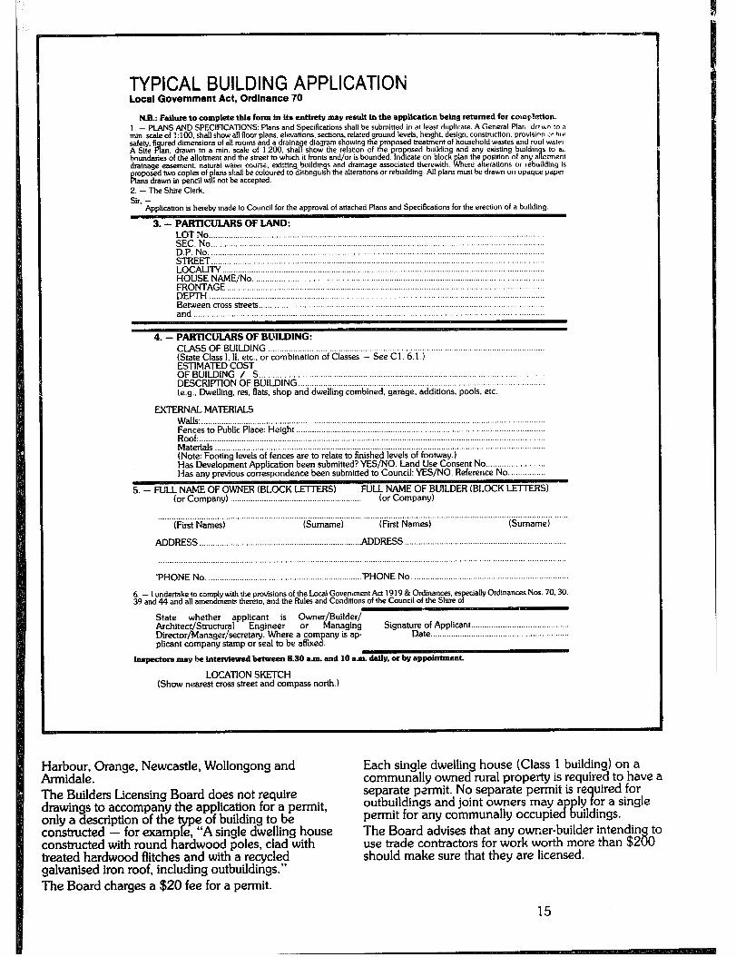
TYPICAL BUILDING APPLICATION Local Government Act, Ordinance 70
N.B.: Fdwe to complete this form In its enttrety may result In the application being returned for complctlon. 1 - PLANS AND SPECIRCATIONS. Plans and Specifications shall be submitted in at least duplicate. A General Plar,. driun to a min. sale of ::lOO. shall show all floor plans. elevations. sections. related ground levels. height. design. conshuction. provistr‘n of hw safety. fi
A red dimensions of all moms and a draina ropased treatment of household wastes and roof water
A Site an. drawn to a min. scale of 1.200. shal 9 e diagram showtng the show the relation of buildin s to a~,
bwndaties of the allotment and the street to which it fronts and/or is osed building and any existing
Ian the position of any a il ohnent drainage easement. nahimi warer cirrirs~. existing buildipgs and drainage associated therewith Rrh ere alterations or rebuilding IS
mposed two copies of plans shall be coloured to dichngulsh the alterations or rebudding. All plans must be drawn on opaqur paper A ans drawn in pencil will not be accepted.
2. - The Shire Clerk.
Sir. - Application is hereby made to Council for the approval of attached Plans and Specifications for the erection of a building.
3. - PARTICUIARS OFIAND: LOT No ........................................................................................................................... ................ SEC. No ...................................................................................................................................... ........... D.P. No. .............................................................................................................................................. STREET ........................................................................................................................... .................. LOCALFrY ............................................................................................................................ ................ HOUSE NAME/No. ............ ................................................................................................................ FRONTAGE ....................................................................................................... ........... ................ ..... DEFIH .............................................................. .............................................................................. Bet.veen cross streets .......................................................................................................................
4. - PARTICULARS OF BUILDING: CLASS OF BUILDING ..,............_ _....__._..................,.....,.,....,........ (State Class 1. II. etc., or combination of Classes - See Cl. 6.1 ) ESTfMATED COST OF BUILDING / S ..___.__....,,,... _.._.._...................................,....,.,,....................,. ..,........_ DESCRIPTION OF BUILDING . . . . . . . . . . . . . . . . . . . . . . . (e.g., Dwelling, res, flats, shop and dwelling combined, garage, additions, pools, etc.
ExTERNALMATERlALs Walls: __ Fences to Public Place: Height ,___._,.._...._.._.,....,..,....,.........................................,.,,................................ Roof:. __ ___ __ ___ Materials __ ___ (Note: Footing levels of fences are to relate to finished levels of footway.) Has Development Application been submitted? YES/NO. Land Use Consent No . . . . . . . . Has any previous correspondence been submitted to Council: YES/NO. Reference No.
5. - FULL NAME OF OWNER (BLOCK LETTERS) FULL NAME OF BUILDER (BLOCK LETTERS) (or Company) ____________.____._.,....,...,............................ for Company)
(First Names) (Surname) (First Names) (Surname)
ADDRESS _...._....._.,_,,....,..........,,............................,,,...,... ADDRESS . . . . . . . . . . . . . .._.......................................................
....... ........................................................................................................
‘PHONE No. ................................................................... ‘PHONE No. ...........................................................
6. - I tmdeltake to comply with the provisions of the Local Govemment Act 1919 &Ordinances. es 39 and 44 and all a~~~endmentz thereto. and the Rules and Conditions of the Council of the Shire o P
ecially Ordinances NOS 70.30.
State whether applicant is Owner/Builder/ Architect/Structural Engineer or Managing Director/Manager/secretary. Where a company is ap
Signature of Applicant ..__.___._..______.....,,.,.,.............. Date .,,...,,._,_.................................................
plicant company stamp or Seal to be affixed.
lnspoctors may be lntelvlewQ!d betweea 8.30 a.m. and 10 am. dalfy. or by appointment.
LOCATfON SKETCH (Show nearest cross street and compass north.)
Harbour, Orange, Newcastle, Wollongong and Armidale. The Builders Licensing Board does not require drawings to accompany the application for a permit, only a description of the
‘yp e of building to be
constructed - for examp e, “A single dwelling house constructed with round hardwood poles, clad with treated hardwood flitches and with a recycled galvanised iron roof, including outbuildings.” The Board charges a $20 fee for a permit.
Each single dwelling house (Class 1 building) on a communally owned rural property is required to have a separate permit. No separate permit is re uired for outbuildings and joint owners may a permit for any communally occupie CR
ly 4 or a single uildings.
The Board advises that any owner-builder intendin to use trade contractors for work worth more than $2 8 0 should make sure that they are licensed.
Insurances Homebuilders are advis,od to ensure that they are adequately covered for Third Farty/Public Risk by an appropriate insurance policy, which would cover visitors and helpers on the site against accident. Worker’s compensation insurance would be necessary if the owner employs any contract or casual labour. Licensed trade contractors are covered by their own insurance. Homebuilders may wish to insure themselves against any risks normally incurred during construction work tith a personal accident policy.
Appeals and Objections Appeals and objections are the homebuilder’s means of redressing grievances against the law or its interpretation. An appeal may be diretied against a Council’s interpretation of tile Local Government Act and Ordinances, or its use of its discretionary powers in relation to a particular case. An objection is directed a ainst a particular provision of the Act or Ordinances, 9, w ich only the Courts have power to modify.
Appeals a less camp ex, than objections to the Act. P
ainst decisions are far more common, and
A right to appe.31 arises when an applicant is aggrieved by any decision, neglect or delay by a Council in relation to Development Ap
P lications, Building
Applications. Movable Dwe!.mg licences, or Occupation before completion Before a homebuilder takes the step of appealing to the Courts, it ma
yh be possible to ask the Council, through
its Town or S ire Clerk, to reconsider its decision in the light of extra information and discussion, or to reach some form of compromise. Appeals a
cp ainst decisions or conditions relating to
movable wellings must be lodged with the District Court within 90 days. A as above are lodged wi
peals relating to other matters tit the Land and Environment
Court within 12 months; a fee of $25 applies. Forms and information about procedure are available from the Court and at local Courts of Petty Sessions. Councils and responsible authorities are obliged to advise applicants served with notices or directions of the reasons for decisions made in relation to applications, and of the rights of applicants to appeal to the Courts. Under normal circumstances a preliminary conference will be arranged with an assessor. If no agreement is reached the matter will proceed to a hearing. The hearing should be conducted with little formality and technicality and the owner-builder may represent hi/her case without legal assistance.
If contemplating an ap eal, owner-builders shouk witness other cases to I! ecome familiar with the procedures and to decide whether legal assistance should be obtained. Legal aid may be available in ( of genuine hardship.
PROCEDURES DURING CONSTRUCTION Inspections When the ap roval for a Buildi Application t Fl
licant receives ap e local council wi 1 indicate what P
inspections it may wish to make. The applicant m
% ive 48 hours’ notice in writing that the work is rea e inspected, after which time the work ma procl
Some Councils provide cards which shoul 2 be submitted at the appropriate time. The building must be “substantial!
Y commenced”
within 12 months after approval o a Building Application or the approval lapses and an extensi has to be sou no time limit or completion of a building project. 9
ht or another application made. Th
However, if the owner ap the building before
lies for permission to oc camp etion, the! Council may P
impose a time limit for completion of the work.
Variations The positions of proposed openings, doors, winds fixed glazing, etc. shown on the elevations must b adhered to, but ap forthcoming provi s
roval for alterations should be ed they remain adequate in arl
according to the Ordinance (Part 50). Alterations and/or additions to the drawings and s 8
ecification may take place during construction. ouncils require notification of major changes eitl
writing or as an amended drawing, whichever is appropriate. Variations should be discussed with 1 Inspector on site or at the Council OfFices before I are carried out.
PROCEDURES AFTER CONSTRUCTION occupancy An owner must make an application in writing to Council for approval to occu not yet been completed (Or a
y a building which 1 inance 79 Part 3.4(1
The homebuilder or owner should use the form of included in Appendix 2 as a guide for an applicati occupy a building before completion. The Counci permit occupation subject to any conditions appropriate to the particular case, after discussion the owner. If this permission is revoked b it must give at least six months’ notice to x
the Co e occup
its intention to do so.
16
The third part of this handbook describes how the technical provisions of the Ordinance influence design and construction of dwellings, and is intended as a guide to those wishing to carry out this work personally. It has been broken up into four main areas, each corresponding loosely to the stage at which it may be considered during the design process. The scope of each section is set out below.
Conception - The way the site and landscape should influence and be influenced by the buildin also included on basic thermal 2
design. Information is esign concepts.
and structures or by the judicious siting and selection of vegetation.
LANDFORM Local topography is an im ortant consideration for the intending homebuilder in t R at it will determine much of the local micro-climate, the landscape and eneral gardening potential, and the ease with whit a can be constructed.
a building
The slope of the land is also a good indicator of the amount of rainfall runoff that may occur and will determine the extent of clearing that could be carried out without causing erosion problems.
- Minimum requirements of the Ordinance concerning room sizes, ceilin heights, light and ventilation, workmanship an 3 materials, which should be considered at the planning stage.
Structure - Factors affecting choice of a structural system. - The principles of designing stable structural systems. - Provisions for unusual and innovative structures. - The connection of the building to the earth. - Masonry (principally earth) construction. - Timber (principally round bush pole) construction.
Environment - Principles of weatherproofing and enclosure. - Flooring, cladding, roofing, openings.
Services - Principles of cold and hot water supply, gas supply. - Drainage and sanitary works. - Electrical work. - The provision of fireplaces and stoves.
roblems and opportunities ncin
structure, choice of materials an i the planning, ultimate en’oyment of
the dwelling. Hence careful consideration o / site limimtions and potential (most easily done on the site itself) brings its own benefit. Following are some important site considerations.
CLIMATE -AND MICROCLIMATE New South Wales has vast variations in climatic regions ranging from hot humid zones, through to temperate areas and to predominantly cold regions. The design and construction of buildings in different areas should respond to these variations. Failure to do so may produce environments where habitation is made difficult, if not unpleasant. Regional climatic design, however, aoes only part of the wa
Y to producing desirable building forms. The
local c imate, or micro-climate, of an area may be of more fundamental importance to the desi n and therefore an understanding of the specific % uilding site is necessary. iJn!ike regional climates, the micro- climate of a site can be manipulated, either by buildings
ORIENTATION Again, the orientation of the slope is fundamental to both building and landscape considerations. Generally north and north-eastern orientations are most desirable, being less susceptible to frost and overheating. Southern and westerly slopes should generally be avoided as these orientations are most likely to have extreme micro-climatic conditions, that is colder in winter and hotter in summer respectively.
EXPOSURE TO WINDS Winds will vary from region to re significantly, however, local land P
ion. More orms and topography
will vary the regional wind patterns. When a site is being considered, its exposure to winds from different directions should be assessed. It should be noted that not all winds are undesirable: rather, some summer breezes may be most welcome. In assessing a site, consideration should also be given to the future establishment of wind breaks and other structures which may be used to deflect or redirect winds around the building site.
VEGETATION All ve etation, both existing and proposed, should be consi J ered at the same time as the building is planned. The value of vegetation should be seen in tenns of: 1) site micro-climate modification (shade and shelter); 2) soil erosion control; 3) bushfire control; 4) renewable building materials; 5) food crops; 6) the natural ecology of the site.
IMPACT ON SURROUNDINGS The impact of a development on a site can take two forms: visual and ecological. Visual. Homebuilders should carefully consider the
17

INFLUENCE OF SLOPE ON SITE SELECTION
FVOR WILDIN& SIT6 /
SWRFS GRSATER THAN \:5 ARC LIABLE TD ERoSlOIl PRO8LEtlS
G-000 6OkOlHG SITS :
Generally buildings should be sited in areas where clearing will not cause excessive erosion, or in areas where they are not subject to flooding.
scale, size, colour and siting of any building in respect of its surroundings. Ecolo ical.
f Sites are frequently chosen for their visual
appea . However, sites which display the greatest diversity of animal and most vulnerable to buil B
lant life are potentially the in
processes of building and iving may be enough to P development. The simp!e
upset, if not destroy, the ecology of a site, remembering that: - some trees may have to be cleared, thereby destroying the upper protective canop
Y ;
- drainage and waste may upset the ocal water conditions and pollute runoff, - increased traffic (even pedestrian) may damage the ground cover sufficientiy to cause erosion; - domestic gardens produce seeds which can be carried by winds or birds. As a rule of thumb, if a site appears “beautiful” because of its diversi
ty , build elsewhere. With a little hard work,
the homebui der can develop a less vulnerable site and make it beautiful. Remember also that a site chosen for its beauty initially may degenerate quickly once ‘he building is up.
Clt~R00D
DRAINAGE Drainage generally influences the sup 1 and dis osal of water (see section on Drainage an xI&mbing f
OTHER CONSlDERATIONS Electricity and access easements, wildlife, sacred sites, privacy and community, noise, future zonings and so on should be considered.
Site Selection Selection of a site should be made with due regard to local topography, the orientation and angle of slope, existing vegetation, and protected or sheltered areas, as opposed to exposed areas.
LOCAL TOPOGRAPHY Ideally, buildings should be sited a
x half to
two-thirds of the wa u the side o P proximate1
are not exposed to t ix slopes, so at they
e igh winds over the ridges nor in areas susceptible to damp and frost as found in valleys.
18
INFLUENCEOF TOPOGRAPHYONSITE SELECTION
AREAS EXPOSED TO WINDS
AREAS SUSCEPl-IBLG -m DhMP, FRO=, l=lO-DIN’3
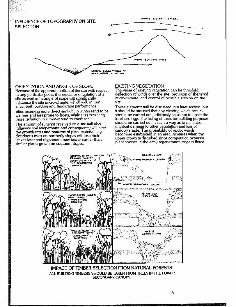
ORIENTATION AND ANGLE OF SLOPE Because of the apparent motion of the sun with respect to any particular point, the aspect or orientation of a site as weii as its angle of s!ope will significantly influence the site micro-climate, which will, in turn, affect both building and landscape performance. Sites receiving more direct sunlight in winter tend to be warmer and less prone to frosts, while sites receiving more radiation in summer tend to overheat. The amount of sunlight received on a site will also influence soil temperature and consequently will alter the growth rates and patterns of plant material, e.g. deciduous trees on northerly slopes wil! lose their leaves later and regenerate new leaves earlier than similar plants grown on southern slopes.
EXISTING VEGETATION Tine value of existing vegetation can be threefold: deflection of winds over the site, provision of sheltered micro-climate, and control of possible erosion on the site. These elements will be discussed in a later section, but it should be stressed that any clearing which occurs should be carried out judiciously so as not to upset the local ecology. The felling of trees for building purposes should be carried out in such a way as to minimise physical damage to other vegetation and loss of canopy shade. The probability of exotic weeds becoming established in an area increases when the u per crown is disturbed since competition between p ant species in the early regeneration stage is fierce. P
;.7 .y, :,::y : ?.,I,;.:..‘.
“.... ,, . 5 _._.., :::.,
,! LOWER SFUJNOQRY ~D~I’““‘-’
IMPACTOFTiMBERSELECTIONFROMNATURALFORESTS ALL BUILDING TIMBERS SHOULD BE TAKEN FROM TREES IN THE LOWER
SECONDARY CANOPY.
PROTECTED OR SHELTERED VERSUS EXPOSED AREAS Two aspects to be considered at this stage are protection from winds, and protection from convective air currents which may bring frosts and fog. Areas exposed to high winds should be avoided since they will cause any building to lose heat rapidly in winter. Areas receiving cooling summer winds, however, are most desirable. Another feature to be considered in this section is the vulnerability of a site to wind-blown bushfires (Foster. 1976). Serious bushfires are invariably driven by winds from predictable wind directions. Consequently, some sites will be found to be fully exposed to such winds, while others lie in wind shadows. A suitable method for examining the effects of winds and bushfires on a site is, once again, to examine the existing ve etation. Areas that are exposed to high winds will P equently have vegetation that is either stunted, with hard leathery leaves, or dis number of broken branches and limbs. -&I
laying a large e soil in these
areas will generally be dryer. Areas receiving less violent winds or those which lie in wind shadows will have soil with a higher moisture content and will be coionised with plants having softer, more delicate leaves. Areas more likei to be affected by bushfires invariably show scars o Y previous bushfires or will be dominated by pioneer species. Convective air currents, while not of great importance in warmer areas, will again affect both building and landscape development. Since cold air is heavier, it settles into the lower areas and flows down the valleys unless impeded by land forms or massive blocks of vegetation. Sites in the direct path of this colder air, or located in the valleys themselves, are obviously less suitable for both energy conservation and solar energy utiiisatior,. 1. See FOSTER Ted: “BUSHFIRE: H&toy. Prevention. Control” SYDNEY, REED; 1976
Landscaping for Energy Conservation Landscaping can form an important, if not inte element of an energy conservation s
2 Y stem an 8
rai, should
be considere at the outset of the bui ding project. Throu h the judicious siting and selection of plants, the imme c? iate micro-climate around the buiidin
i: can be
significantly altered. Plants are able to modi the micro-climate by shelterin undesirable winds, while L?
the building from eflecting desirable winds
through the building, and by controlling the amount of solar radiation striking the building. Plants both intercept and absorb solar radiation, then use the absorbed energy in growth and temperature control. The whit 1:
iants affect temperature by transpiration of water can cool the surrounding environment.
For vegetation to be successful, plant material should be chosen according to the following criteria: - deciduous or evergreen - complete or incomplete canopies - leaf distribution - vertically hanging leaves through to horizontal leaves - transpiration capabilities - high transpiring plants or low transpiring plants. The first three points can be ascertained b the mature plant material, while a rule of t K
inspecting umb can be
used for the fourth. Plant materials with a low transpiration rate are genetiiiy considered as drought tolerant plants and are usually characterised by some modification to the leaf structure: for example the leaves may be small, leathery, have fine hairs or have a waxy quality. Landscape inte ated design can take many forms, but its simplest app ication can be considered in four main H areas: - windbreaks and shelterbelts - the use of plants near buildings - the use of vines - sod or turf roofs, and earth sheltered designs.
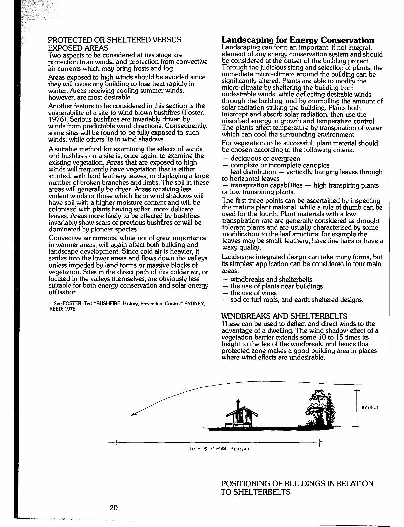
WINDBREAKS AND SHELTERBELTS These can be used to deflect and direct winds to the advantage of a dwelling. The wind shadow effect of a vegetation barrier extends some 10 to 15 times its height to the lee of the windbreak, and hence this protected zone makes a good building area in places where wind effects are undesirable.
I L
10 - 15 nMES HEIGHT
POSITIONING OF BUILDINGS IN RELATION TO SHELTERBELTS
20
SHELTERBELTS FOR HOT CLIMATES
l=OSll-ION SHELTERBELT l-0 V!D=L6LT HoT.DRY, DU5TY WIN05 WUAY FRDM SUILPINQS
~PROTECTIUE IIOUUD :
: COVER. . . .
FBNE CEAF CPNOPY <DUOUciItT R.cSlSXAhiT~
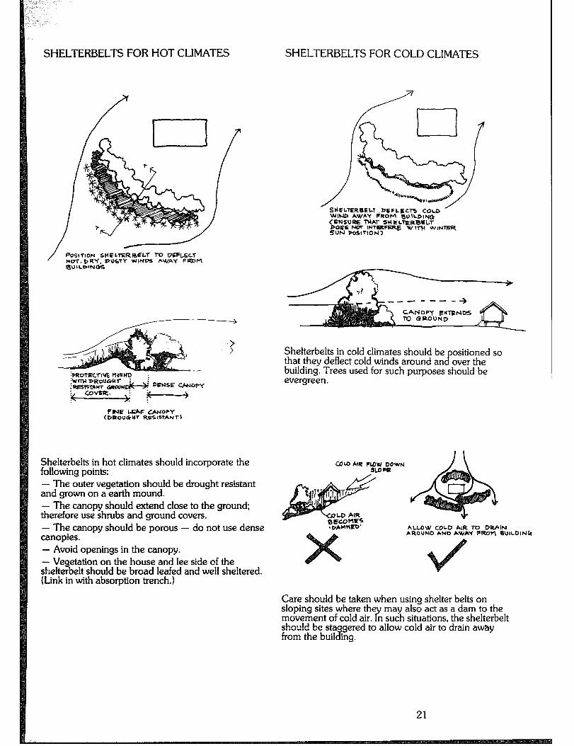
Sheiterbeits in hot climates should incorporate the following points: - The outer vegetation should be drought resistant and grown on a earth mound. - The canopy should extend close to the ground; therefore use shrubs and ground covers. - The canopy should be porous - do not use dense canopies. - Avoid openings in the canopy. - Vegetation on the house and lee side of the shelterbelt should be broad leafed and well sheltered. (Link in with absorption trench.)
SHELTERBELTS FOR COLD CLIMATES
‘SHELTERBELT .DCFLECTJ COLD /
WIND AWAY FROM BI)ILDIY() CPNSURE tyAl- SHELrERBELT DOGS NOT IFlTaFsRE W 1l-H WIN- SON PO5lTIOb4>
Shelterbelts in cold climates should be ositioned so that they deflect cold winds around an cr over the building. Trees used for such purposes should be evergreen.
ALLOW COLD AIR ro DRAIN hROUND hND AWAY FRDPI BUILDINk
Care should be taken when using shelter belts on sloping sites where the may also act as a dam to the moirement of cold air. n such situations, the shelterbelt Y shou!d be sta from the buil 3
gered to allow cold air to drain away ing.
21
THE USE OF PLANTS NEAR BUILDINGS
D WINIER SUN~CISE
SUHMER SUNRISE
I ? SU~H=R TERRAGE
DEC1bUWSlREES m THE NORTH c&f ALJaW UCUSE 70 REt’AIM COOL
DECIDUOUS VINES ON TRELLIS AND OVER RaOF
DEelOU TREES ON NORTH wEsf TO
To-*uce
QEb~~CT ACTL-DLIn.7.I SJMtlER. HIEAT GAIN
TION OF PLANTS FOR SUN CONTROL
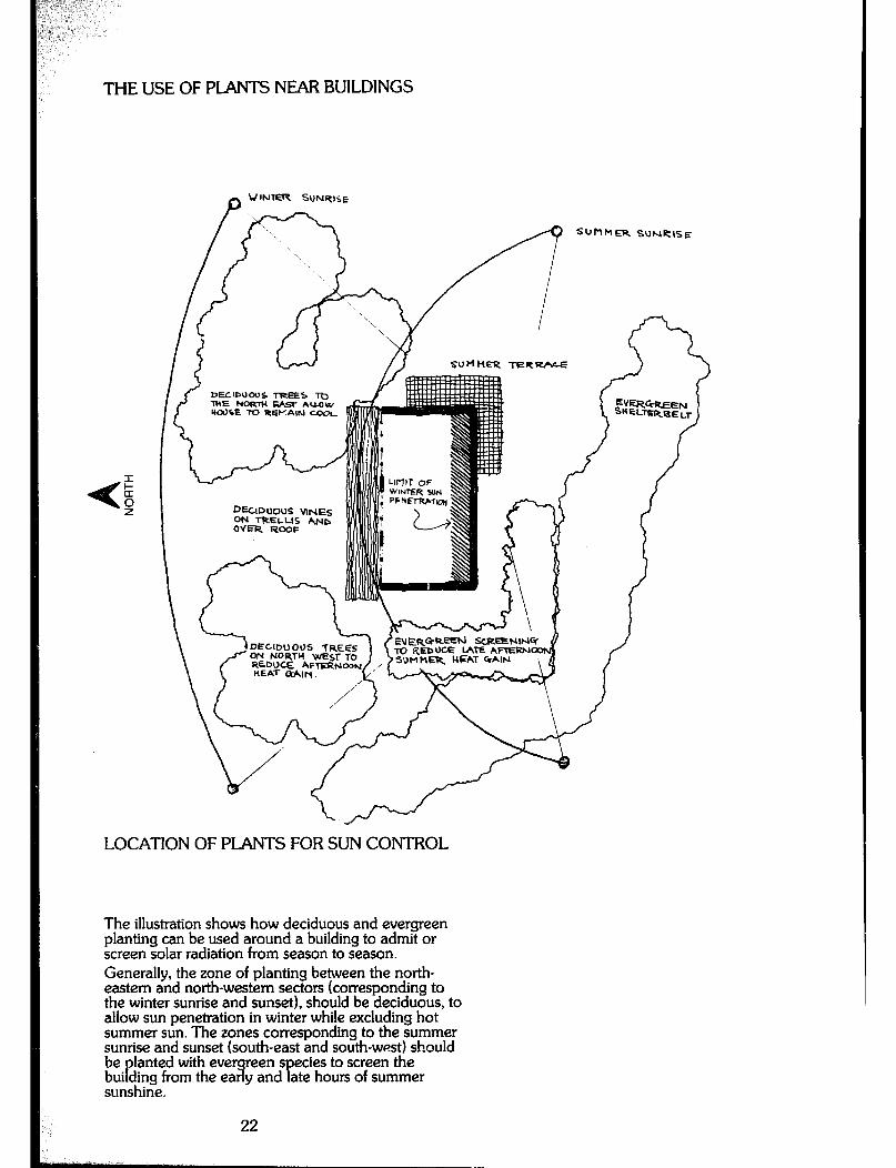
The illustration shows how deciduous and evergreen planting can be used around a building to admit or screen solar radiation from season to season. Generally, the zone of planting between the north- eastern and north-western sectors (corresponding to the winter sunrise and sunset), should be deciduous, to allow sun penetration in winter while excluding hot summer sun. The zones corresponding to the summer sunrise and sunset (south-east and south-west) shou!d be lanted with evergreen s ecies to screen the bui ding from the early and ate hours of summer P P sunshine.
22
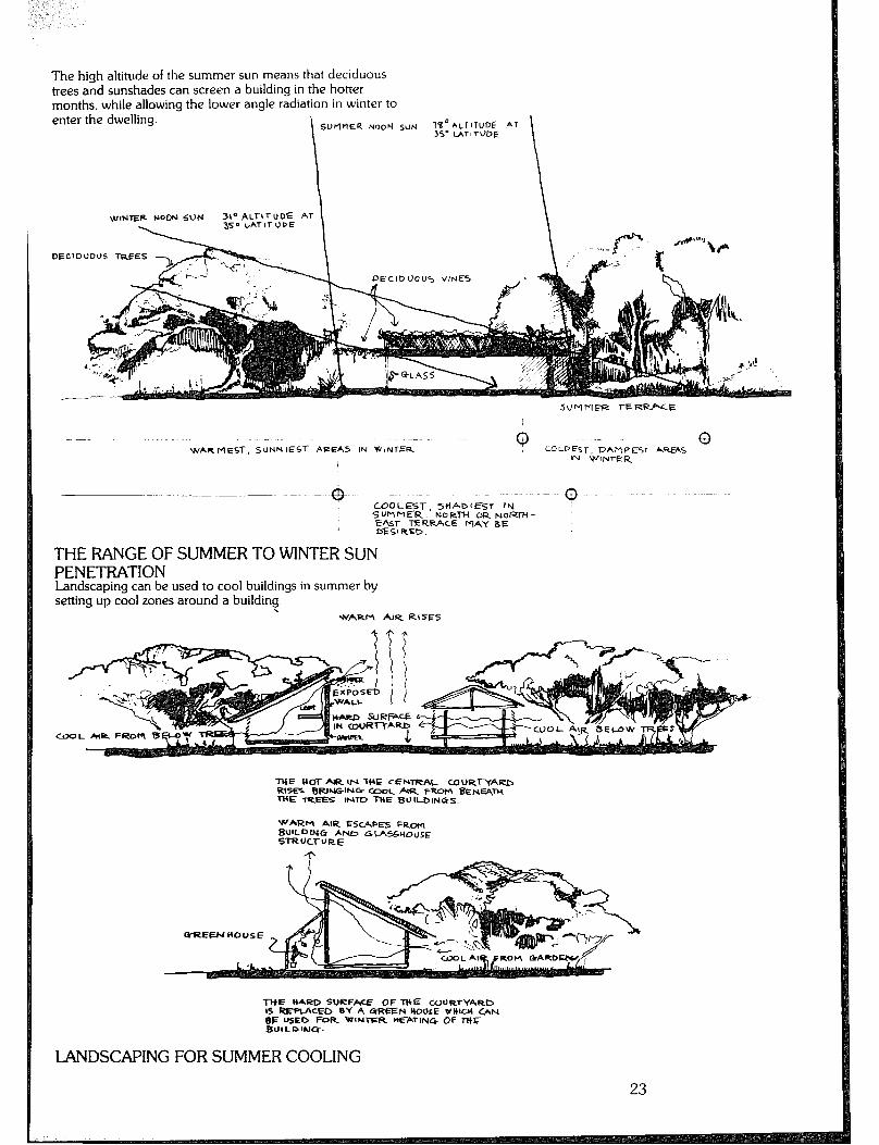
The high altitude of the summer sun means that deciduous trees and sunshades can screen a building in the hotter months. while allowing the lower angle radiation in winter to enter the dwelling. i
1B”ALT1TUD6 AT 35’ LAT, TODE
w!NlER NOON So?4 31~ ALrl l- UDE AT 350 t,ATlTUDE
DECIDUOUS TREES
WARMEST, SUNNlESf AlZEAL IN WINTER 0
LGLf’Esr, DAtlPEST AREAS m ‘h’INJ-E4
- + ~~~-. --- - -~-- --~- COOLEST, S+iADIEST tN
I SUMMER. NORM CR~oRili- 5%~ TERRACE r-+x-f aE DE9 RCfD.
THERANGEOFSUMMERTOWINTERSUN PENETRATION Landscaping can be used to cool buildings in summer by setting up cool zones around a building. \
WARM AIR RISES
THE HOT AR 1f-I THE CENTRAL WURl-YARB RISES BRlNGlNG GZTOL AIR FROM &t&W-H THE TREES INTO THE BULOINGS.
WARM AIR E5cf.P~5 FRC,,.J BUlLPlLIcZ ANb GCA55YOUSf STRUCTVRE
l-WE H4RD SURFACE OF TltE WURTYARO IS REF’IACED BY 4 CrREEH l+Ol%E WlttCbl 0,N BE USED FOR -1NTlZR HEATING Of MF BUILPINCF.
LANDSCAPINGFORSUMMERCOOLING
23

THE USE OF VINES Vines growing on or near a wall can reduce heat gain into a building by as much as 70 per cent, as well as reducing heat loss by 30 per cent. It can therefore be considered as an option to insulation.
DECIDUOUS
THE USE OF VINES FOR INSUIATION
nE5n
%
%REEN HOUSES USED TD HEAT -WE DU~lblNG IN ‘.WNT,%Z CAN BE WE COOL BY USlr4e A DECIDUWS VINE
NOTE: If vines are to be grown directly on a wall, choose both plant and materials carefully, e.g. do not use vines directly on earth walls (use a supporting structure away from such walls). Provide support structure consistent with the plants climbing mechanism. Climbing Support structure Examples mechanism Tendril mesh Grape (vitis species)
Twiner timber struts Honeysuckle (Ionicera species)
Scrambler solid support e.g. timber
Bougainvillea species
Clinging sucker pads Parthenocissus species
Note: Vines should be planted at small intervals to promote vertical growth. Walls and roof not facing north should use evergreen vines.
24
DAM? PROOF
USE OF Sota CON~TFLUCTION FOR INSUUTION
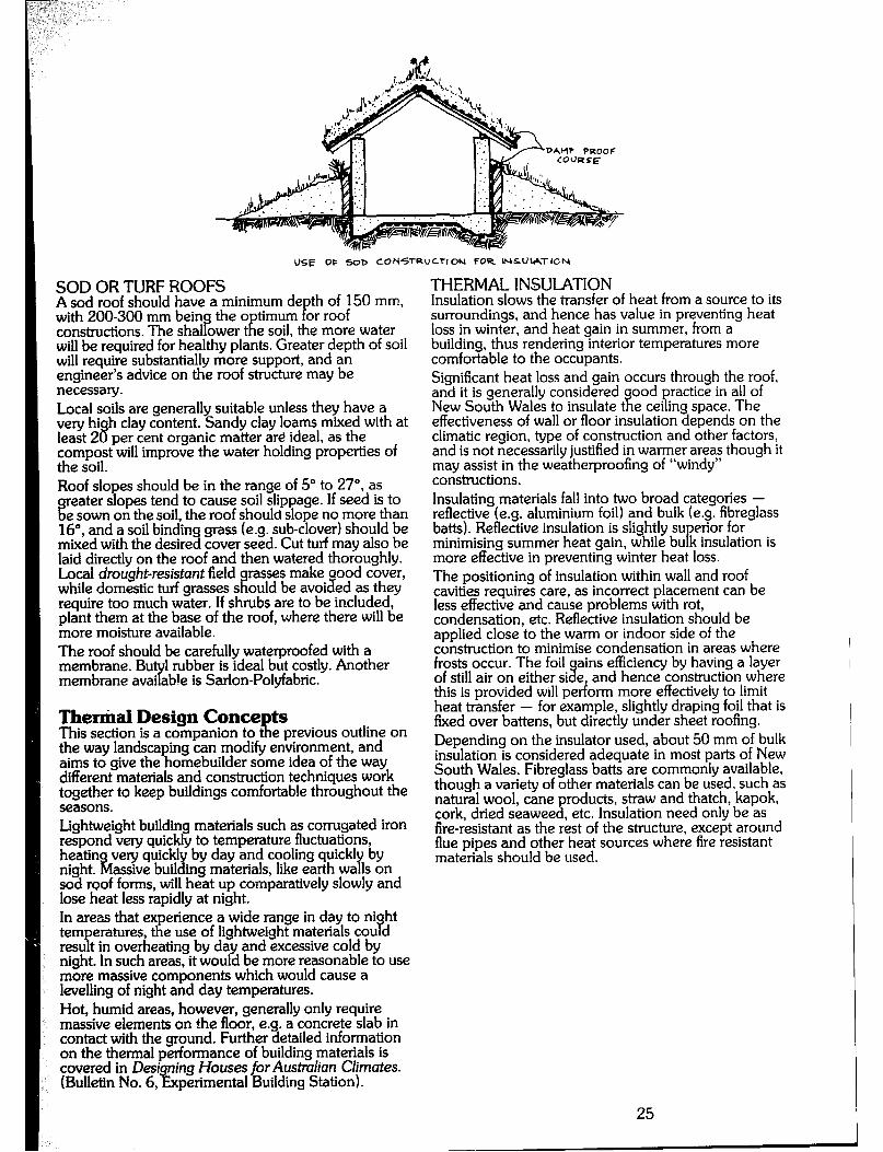
SOD OR TURF ROOFS A sod roof should have a minimum de th of 150 mm, with ZOO-300 mm bein the o timum or roof constructions. The shalbwer &e soil, !ie more water will be required for healthy plants. Greater depth of soil will require substantially more support, and an engineer’s advice on the roof structure may be necessay. Local soils are generally suitable unless they have a very hi least 2 8
h clay content. Sandy clay loams mixed with at per cent organic matter are ideal, as the
compost will improve the water holding properties of the soil. Roof slo es should be in the range of 5” to 27”, as
eater s opes tend to cause soil slippage. If seed is to Q
P e sown on the soil, the roof should slope no more than
16”, and a soil binding grass (e.g. sub-clover) should be mixed with the desired cover seed. Cut turf may also be laid directly on the roof and then watered thoroughly. Local drought-resistant field
r ses make aood cover,
while domestic turf grasses s ould be avoided as they require too much water. If shrubs are to be included, plant them at the base of the roof, where there will be more moisture available. The roof should be carefully waterproofed with a membrane. Bu 1 rubber is ideal but costly. Another membrane avai able is Sarlon-Polyfabric. ty
Therxid Design Conce ts This section is a companion to 5: e previous outline on the way landscaping can modify environment, and aims to give the homebuilder some idea of the way different materials and construction techniques work together to keep buildings comfortable throughout the seasons. Lightweight building materials such as corrugated iron respond very quickly to temperature fluctuations, heatin very quickly by day and cooling quick1
z4 Y by
night. assive building materials, like earth wa Is on sod roof forms, will heat up comparatively slowly and lose heat less rapidly at night. In areas that experience a wide range in day to ni ht temperatures, the use of lightweight materials cou d H result in overheating by day and excessive cold by night. In such areas, it would be more reasonable to use more massive components which would cause a levelling of night and day temperatures. Hot, humid areas, however, generally only require massive elements on the floor, e.g. a concrete slab in contact with the ground. Further detailed information on the thermal performance of building materials is covered in Desi (Bulletin No. 6,
ing Houses for Austmlian Climates. i% perimental Building Station).
THERMAL INSULATION Insulation slows the transfer of heat from a source to its surroundings, and hence has value in preventing heat loss in winter, and heat gain in summer, from a building, thus rendering interior temperatures more comfortable to the occupants. Significant heat loss and gain occurs through the roof, and it is generally considered New South Wales to insulate t
ood practice in all of it e ceiling space. The
effectiveness of wall or floor insulation depends on the climatic region, type of construction and other factors, and is not necessarily justified in warmer areas though it may assist in the weatherproofing of “windy” constructions. Insulating materials fall into two broad categories - reflective (e.g. aluminium foil) and bulk (e.g. fibreglass baits). Reflective insulation is slightly su
P erior for
minimising summer heat gain, while bu k insulation is more effective in preventing winter heat loss. The positioning of insulation within wall and roof cavities requires care, as incorrect placement can be less effective and cause problems with rot, condensation, etc. Reflective insulation should be applied close to the warm or indoor side of the construction to minimise condensation in areas where frosts occur. The foil ains efficiency by having a layer of still air on either si % e, and hence construction where this is provided ~111 perform more effectively to limit heat transfer - for example, slightly draping foil that is fixed over battens, but directly under sheet roofing. Depending on the insulator used, about 50 mm of bulk insulation is considered adequate in most parts of New South Wales. Fibreglass batts are commonly available, though a variety of other materials can be used, such as natural wool, cane products, straw and thatch, kapok, cork, dried seaweed, etc. Insulation need only be as fire-resistant as the rest of the structure, except around flue pipes and other heat sources where fire resistant materials should be used.
25 I
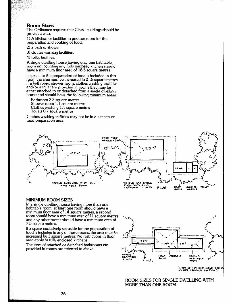
Room Sizes The Ordinance requires that Class I buildings should be provided with: 1) A kitchen or facilities in another room for the preparation and cooking of food; 2) a bath or shower, 3) clothes washing facilities; 4) toilet facilities. A single dwelling house having only one habitable room not countin have a minimum i
any fully enclosed kitchen should oor area of 18.5 square metres.
If space for the preparation of food is included in this room the area must be increased to 21.5 square men-es. If a bathroom, shower room, clothes washing facilities and/or a toilet are provided in rooms they may be either attached to or detached from a single dwelling house and should have the following minimum areas:
Bathroom 2.2 square metres Shower room 1.1 square metres Clothes washing 1.: square metres Toilets 0.7 square rnetres
Clothes washing facilities may not be in a kitchen or food preparation area.
,. - . . . . . . . . . FOob PRE?- 1’~.
--- -......,..,...........~....... - MAlKN - 3ma, i . . .
‘. I i
I. . .._ wd
5
._ . . . . 1T.T *= I,.- _...__._... . . . . . I . . . . . . _:’ R- .: . . . . . . . . . .._.___._ _. ._..._...,_. . . . . . . . . . .._ ,. ,. - -
SIN4LE DWELLINGS WII-II ONE HAEITABLE ROOM
SINGLE HABITABLE mxml WITH PO-C’ PuEPAmArloI.4
.lU
HEA PLUS
MINIMUMROOMSIZES In a sin
? le dwelling house having more than one
habitab e room, at least one room should have a minimum floor area of 14 square metres, a second room should have a minimum area of 11 square metres and any other rooms should have a minimum area of 7.5 square metres. If a space exclusively set aside for the preparation of food is included in any of these rooms, the area must be increased by 3 square metres. No restrictions in floor area apply to fully enclosed kitchens. The sizes of attached or detached bathrooms etc. provided in rooms are referred to above.
(SIZE5 OF NON dY!rABLE RCOP AS f=U PRC’JIOUS SGCTION )
ROOMSlZESFORSINGLEDWLLINGWITH MORETHANONEROOM
26
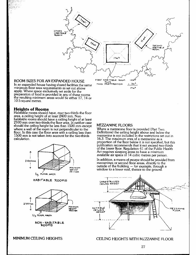
ROOM SIZES FOR AN EXPANDED HOUSE FIRST W3&=.6LE RobI- t4*
In an expanded house having shared facilities the same FOOD PRE~~lV.flON + 3nl
minimum floor area requirements as set out above 17mZ
apply. Where s ace exclusively set aside for the preparation of ood is provided in any of these rooms P the resulting minimum areas would be either 17, 14 or 10.5 square metres.
2400Mm In addition, a means of escape should be provided from
1
mezzanines or second floor areas, directly to the outside of the building - for example, throu
I?3 h a
/ window to a lower roof, thence to the grou
4.5 FLWR AizEA
--r-------‘ __ _ --- ._ ._
HABITABLE ROOMS
Heights of Rooms Habitable rooms should have, over two-thirds the floor area, a ceiling height of at least 2400 mm. Non- habitable rooms should have a ceiling height of at least 2100 mm over two-thirds the floor area. In neither case should the ceiling height be less than 1500 mm except MEZZANINE FLOORS where a wall of the room is not perpendicular to the floor. !n this case the floor area with a ceiling less than
Where a mezzanine floor is provided (Part Two,
1500 mm is not taken into account for the two-thirds Definitions) the ceiling height above and below the mezzanine is not included in the restrictions set out in
calculation. 16.3. The maximum area of a mezzanine as a proportion of the floor below it is not specified, but this publication recommends that it not exceed two-thirds of the lower floor. Regulation 41 of the Public Health Act requires sleeping areas to have a minimum available air space of 14 cubic metres per person.
Z/3 _-
NON&;A$iTA B LE
MINIMUM CEILING HEIGHTS CEILING HEIGHTS WITH MEZZANINE FLOOR
27

Light and Ventilation The Ordinance requires that habitable rooms be provided with windows “having an aggregate Ii ht transmitting area of not less than one-tenth the ?I oor area of the room concerned” (Part 50.212)) and with “permanent openings, windows, doors or other devices which are capable of being opened. having an aggregate opening or opepable size of not less than one-twentieth the’ floor = ; i of the room concerned” (Part 5O.N 1)). Where a room has no openin exterior, but opens into another room or enc osed B
s to the
verandah. it must have the same openings as above, and the adjoinin room must have openin s providing for one-tenth of t 8, e combined floor areas or light P transmission, and one-twentieth of the combined floor areas for ventilation.
Workmanship There is little guidance in the Ordinance concerning the very impotiant aspect of workmanshi
E Clause 10.1
states: “Every art of a building shall e erected in a good and wor R manlike manner.” This handbook assumes that the owner-builder, while perhaps lacking the specialised trainin
7 and experience
of man Er’
builders and tradespeople, wi 1 make up for any de cienc through the caution and care which will be exercised g y those who have to live with the consequences of their own design decisions and handiwork. Well-executed work is obviously desirable, be it sophisticated and expensive, or low cost using sound recycled materials. Principles such as antcapping, water shedding. subfloor ventilation, adequate bracing and maintenance are fundamental to the furthering of a building’s natural life. which makes sense in an era of growing resource scarcity and pressure. Do it once. and do it well!
Materials CHOICE OF tiATERIALS The choice of materials is intimately bound up with the task required to be performed, over what period of time. and the manner in which they can be put together so that “a good and workmanlike ’ job can be executed. for the reasons previously mentioned. Information concerning the pro
P erties and detailing of
building materials is widely avai able, though the use of different materials and techniques varies from region to region. In general. homebuilders should try to maximise the use of local building resources, to the extent of retrievin materials irom their own sites, such as earth or roun cp timber poles.
QUALITY OF MATERIALS Materials. either new or second hand, which are dan erous to health. faulty or unsuitable (Ord. 70 Part 10.3 should not be used in the construction of a building. e.g. hazardous materials containing toxic substances, timbers from disused mines, or materials that have been used in the construction of a cesspit, drain or sewer. The Council itself may test any material used or proposed to be used. or may require documentary
evidence in the form of a report from a competent testing authori
# such as the Commonwealth Scientific
and Industrial esearch Organisation, an Accreditation Certificate from the Director of the Experimental Building Station, or any other form of documentary evidence which in the opinion of the Council is satisfactoy. Many materials are required to conform with Australian Standards - see Appendix 9 for the appropriate Standards and Codes of Practice.
RECYCLED MATERIALS Homebuilders may consider using sound secondhand and recycled materials and components. Demolition sites may provide structural members, cladding, roofing, doors, windows, flooring and other joiney. These should be repaired, made good and trimmed as necessary.
OTHER MATERIALS Certain materials may be used to provide short term waterproofing or as temporary enclosure in staged construction. Any long term use of these materials, with replacement as necessary should be negotiated with the building inspector.
STRUCTURE This section deals with some of the factors homebuilders should consider regarding the choice of structure for any dwelling. It is not intended as a design guide to the characteristics of different structural systems as such a guide is beyond the scope of this handbook, but rather as an indication of the factors influencing the choice of structure, and the structural principles involved in making a building sound.
Factors Influencing Choice of Structure 1) Ap roof, R
ropriateness of a structural system in providing oor or wall spans consistent with the desired
room layout. 2) The local availability of structural materials, or the logistics involved in transporting different materials to remote sites. 3) Initial costs of different structural materials, and the amount of skilled or unskilled labour and plant required to erect or fix them. 4) Ability of a structural system to provide shelter before the corn level (e.g.
letion of all construction up to the roof load- E earing masonry needs to be completed
before roofing can be commenced). 5) Environmental considerations regarding the ethics of materials production; energy content, durability and maintenance requirements; recyclability; local vernacular; ease of adaptation to changing living patterns; and so on.
Structural Princi P
les The homebuilder shou d answer two basic questions in relation to the structural soundness of a building: Is the arrangement of structural members a stable arrangement? What is the required size of each structural member? Structural members include beams, columns, bearers,
28
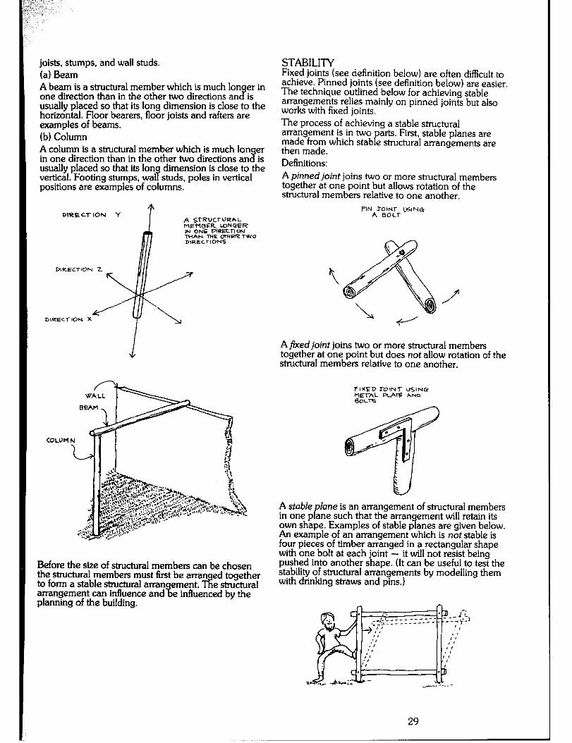
joists, stumps, and wall studs. (a) Beam A beam is a structural member which is much Ion
3 er in
one direction than in the other two directions an is usually placed so that its long dimension is close to the horizontal. Floor bearers, floor joists and rafters are examples of beams. (b) Column A column is a structural member which is much Ion er in one direction than in the other two directions an % is usually placed so that its lon dimension is close to the vertical. Footing stumps, wal studs, poles in vertical s positions are examples of columns.
PIRE Cl-ION -f A STRVCI-URAL MEP’IBER LDNGER IN ONE DIRECl7W.I THAN -WE mtlm? TWO DIRECTIONS
DIRECTlOW Z
DlREC,-ION X
Before the size of structural members can be chosen the structural members must first be arran to form a stable structural arran Tit
ed together ement. e structural
arrangement can influence and % planning of the building.
e influenced by the
STABILITY Fixed joints (see definition below) are often difficult to achieve. Pinned joints (see definition below) are easier. The technique outlined below for achieving stable arrangements relies mainly on pinned joints but also works with fixed joints. The process of achieving a stable structural arrangement is in two made from which P
arts. First, stable planes are
then made. stab e structural arrangements are
Definitions: A pinned joint joins two or more structural members together at one point but allows rotation of the structural members relative to one another.
P’NA”cx& ISING
A fixed joint joins two or more structural members together at one point but does not allow rotation of the structural members relative to one another.
F I%FD 3-OINT USIN&
izz!- -lz AND
A stable P
lane is an arrangement of structural members in one p ane such that the arran
9 ement will retain its
own shape. Examples of stable p anes are given below. An example of an arrangement which is not stable is four pieces of timber arranged in a rectangular shape with one bolt at each joint - it will not resist being pushed into another shape. (It can be useful to test the stability of structural arrangements by modelling them with drinking straws and pins.)
29
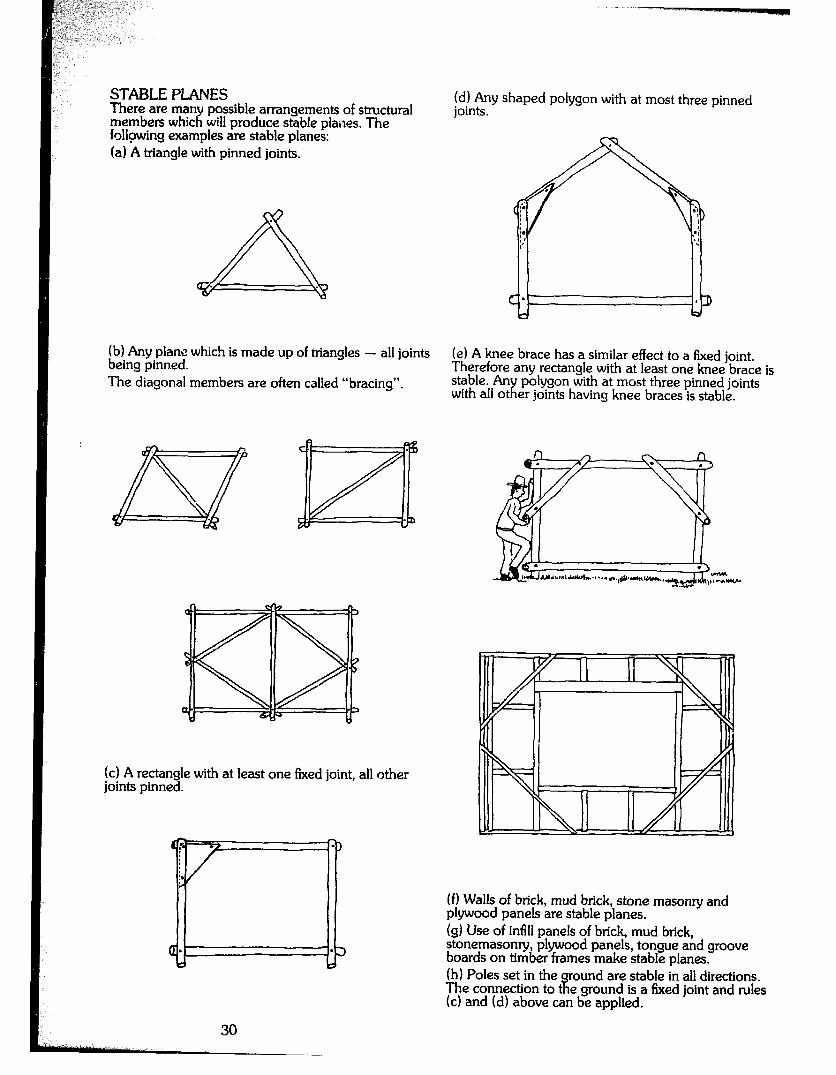
(b) Any plane which is made up of mangles - all joints being pinned.
(e) A knee brace has a similar effect to a fixed joint. Therefore any rectangle with at least one knee brace is
The diagonal members are often called “bracing”. stable. An with all ot x
polygon with at most three pinned joints er joints having knee braces is stable.
(cl A rectangle with at least one fixed joint, all other joints pinned.
(f) Walls of brick, mud brick, stone masonry and plywood panels are stable planes. (g) Use of infill panels of brick, mud brick, stonemasonry, plywood panels, tongue and groove boards on timber frames make stable planes. (h) Poles set in the ound are stable in all directions. The connection to if e ground is a fixed joint and rules (4 and fd) above can be applied.
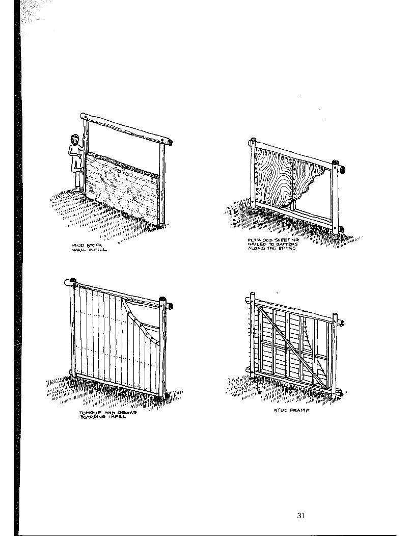
r-lUD B’pI= WALL INFlU-
STUD FRhME TCWGUE P.NJJ CiUOoVE BC&+RPINC INFILL
31
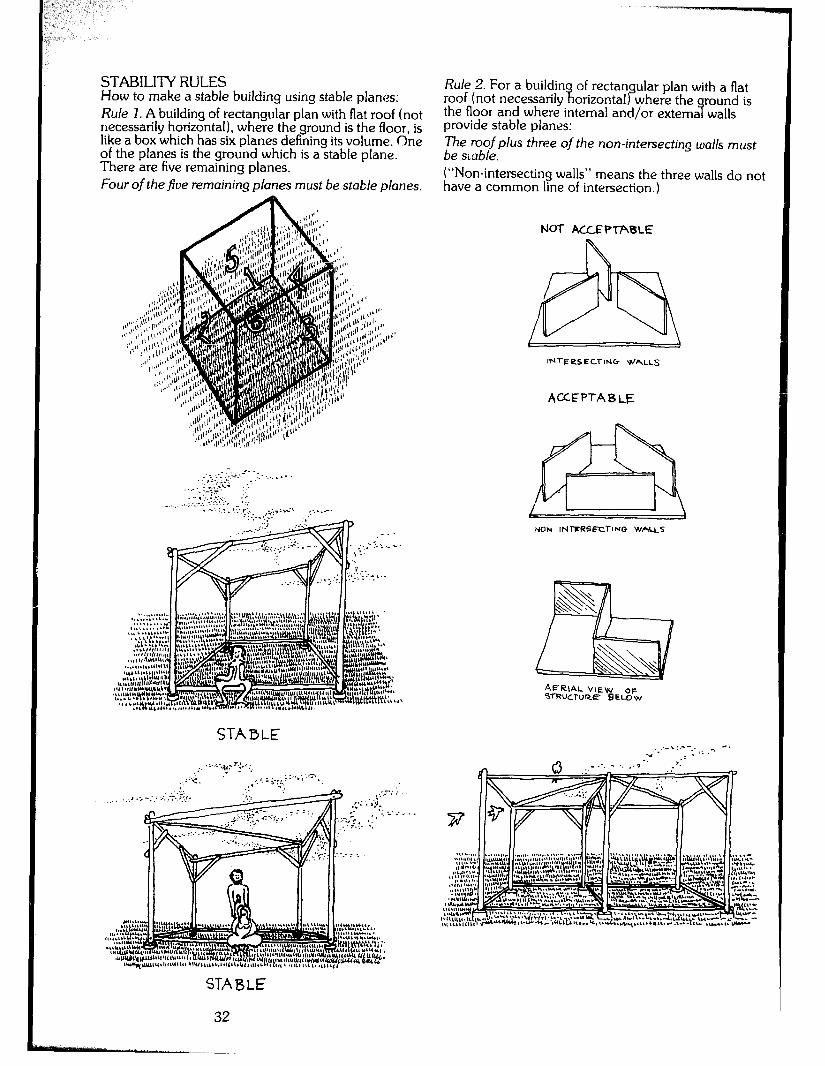
STABILI-IY RULES How to make a stable building using stable planes: Rule 1. A building of rectangular plan with flat roof (not necessarily horizontal), where the ground is the floor, is like a box which has six planes defining its volume. One of the planes is the ground which is a stable plane. There are five remaining planes. Four of the five remaining planes must be stat/e planes.
Rule 2. For a buildin roof (not necessarily ?I
of rectangular plan with a flat orizontal) where the round is
the floor and where internal and/or extema walls 9 provide stable planes: The roof plus three of the non-intersecting walls must be smble. (“Non-intersecting walls” means the three walls do not have a common line of intersection.)
Nol- ACLFPTABLE
,,ON INl-FRSECl-lNG WAUS
AERIAL VIEW OF WRUCTURE BELoW
STABLE
STABLE
32
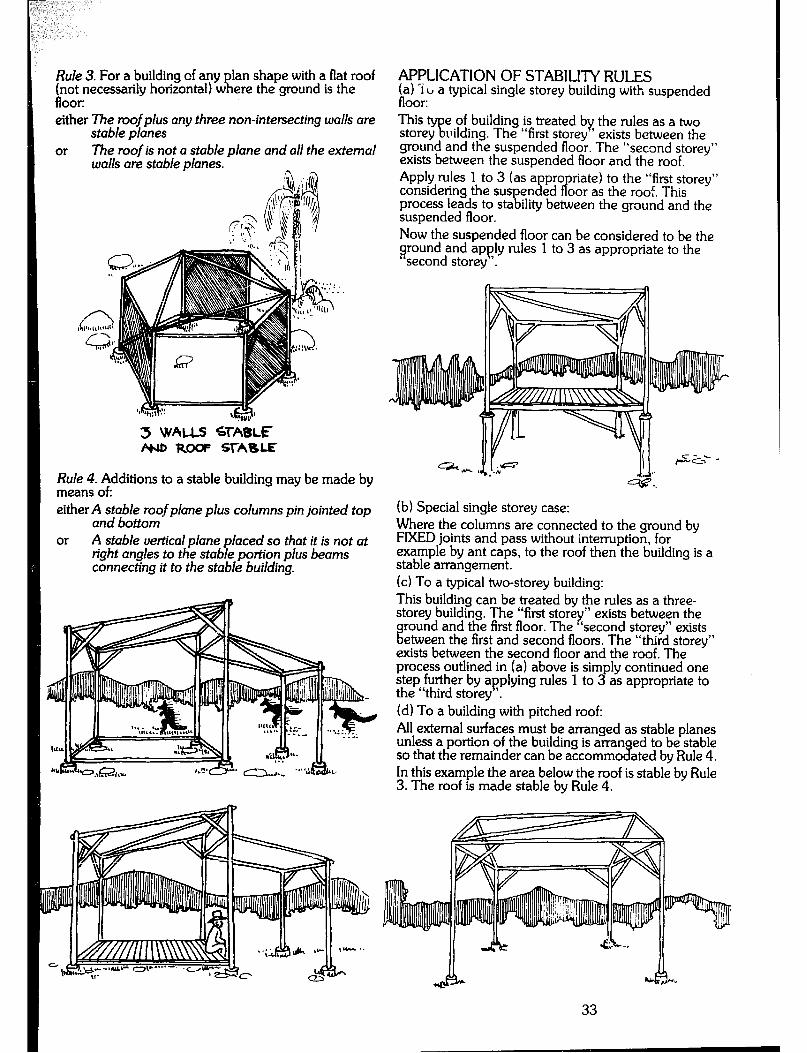
Rule 3. For a building of any plan shape with a flat roof (not necessarily horizontal) where the ground is the floor: either The roof plus any three non-intersecting walls are
stable planes or The roof is not a stable plane and all the external
walls are stable w/ones.
3 WAUS STABLE #4D Rm STABLE
Rule 4. Additions to a stable building may be made by means of: either A stable roof plane plus columns pin jointed top
and bottom or A stable vertical plane placed so that it is not at
right angles to the stable portion plus beams connecting it to the stable building.
APPLICATION OF STABILITY RULES (a) ‘i CI a typical single storey building with suspended floor: This e
fyg storey of building is treated by the rules as a two
llilding. The “first storey ’ exists between the ground and the suspended floor. The “second storey” exists between the suspended floor and the roof. Apply rules 1 to 3 (as appro
P riate)
considering the suspended to the “first storey”
oor as the roof. This process leads to stability between the ground and the suspended floor. Now the suspended floor can be considered to be the around and apply rules 1 to 3 as appropriate to the second storey ‘.
(b) Special single storey case: Where the columns are connected to the ground by FIXED joints and pass without interruption, for example by ant caps, to the roof then the building is a stable arrangement. (cl To a typical two-storey building: This building can be treated by the rules as a three- storey building. The “first storey” exists between the
% round and the first floor. The ‘second storey” exists etween the first and second floors. The “third storey”
exists between the second floor and the roof. The process outlined in (a) above is simpiy continued one step further by applying rules 1 to 3 as appropriate to the “third storey ‘. (d) To a building with pitched roof: All external surfaces must be arranged as stable planes unless a portion of the building is arran ed to be stable so that the remainder can be accommo % ated by Rule 4. In this example the area below the roof is stable by Rule 3. The roof is made stable by Rule 4.
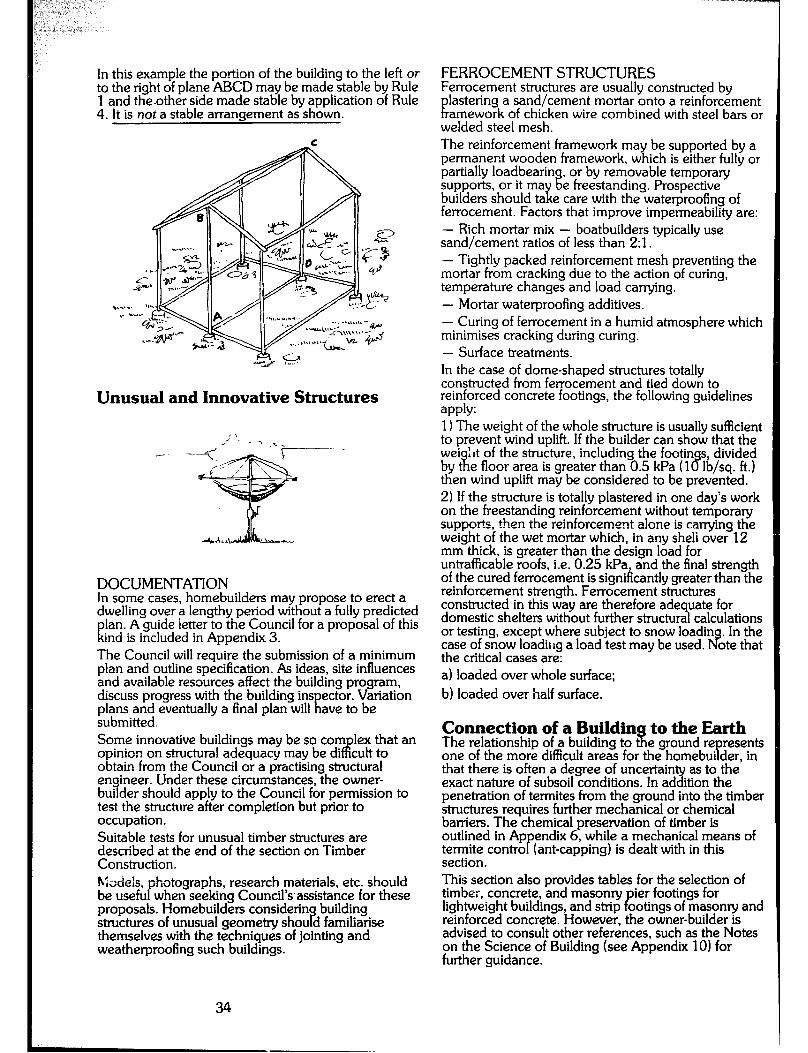
In this example the portion of the building to the left or to the right of plane ABCD may be made stable by Rule 1 and the.other side made stable by application of Rule 4. It is not a stable arrangement as shown.
Unusual and Innovative Structures
DOCUMENTATION In some cases, homebuilders may propose to erect a dwelling over a iengthy period without a fully predicted
K lan. ind
A guide letter to the Council for a proposal of this is included in Appendix 3.
The Council will require the submission of a minimum plan and outline specification. As ideas, site influences and available resources affect the building program, discuss progress with the building ins ector. Variation plans and eventually a final plan will t: ave to be submitted. Some innovative buildings may be so corn lex that an opinion on structural adequacy may be di P cult to obtain from the Council or a practising sttuctural engineer. Under these circumstances, the owner- builder should apply to the Council for permission to test the structure after completion but prior to occupation. Suitable tests for unusual timber structures are described at the end of the section on Timber Construction. hbdels, be usefu P
hotographs, research materials, etc. should when seeking Council’s.assistance for these
proposals. Homebuilders consider-in P
building structures of unusual geometry shou d familiarise themselves with the techniques of jointing and weatherproofing such buildings.
FERROCEMENT STRUCTURES Ferrocement structures are usually constructed by
lastering a sand/cement mortar onto a reinforcement tc amework of chicken wire combined with steel bars or welded steel mesh. The reinforcement framework may be supported by a permanent wooden framework, which is either fully or partially loadbearin , or by removable temporary supports, or it ma builders should ta E
% e freestanding. Prospective e care with the waterproofing of
ferrocement. Factors that improve impermeability are: - Rich mortar mix - boatbuilders typically use sand/cement ratios of less than 21. - Tightly packed reinforcement mesh preventing the mortar from cracking due to the action of curing, temperature changes and load carrying. - Mortar waterproofing additives. - Curing of ferrocement in a humid atmosphere which minimises cracking during curing. - Surface treatments. In the case of dome-shaped structures totally constructed from ferrocement and tied down to reinforced concrete footings, the following guidelines apply: 11 The weight of the whole structure is usually sufficient to prevent wind uplift. If the builder can show that the wei s, divided by t 1
ht of the structure, including the footin e floor area is greater than 0.5 kPa (1 % lb/sq. ft.)
then wind uplift may be considered to be prevented. 21 If the structure is totally plastered in one day’s work on the freestanding reinforcement without temporary supports, then the reinforcement a!one is carrying the weight of the wet mortar which, in any sheli over 12 mm thick, is greater than the design load for untrafficable roofs, i.e. 0.25 kPa, and the final strength of the cured ferrocement is significantly greater than the reinforcement strength. Fenocement structures constructed in this way are therefore adequate for domestic shelters without further structural calculations or testing, except where subject to snow loadin . In the case of snow loading a load test may be used. P? ote that the critical cases are: al loaded over whole surface; bl loaded over half surface.
Connection of a Buildin to the Earth The relationship of a building to i!t e ground re resents one of the more difficult areas for the homebui der, in P that there is often a degree of uncertainty as to the exact nature of subsoil conditions. In addition the penetration of termites from the ground into the timber structures requires further mechanical or chemical barriers. The chemical preservation of timber is outlined in Ap endii 6, while a mechanical means of termite contra P (ant-capping) is dealt with in this section. This section also provides tables for the selection of timber, concrete, and masonry ier footings for lightweight buildings, and strip ootings of masonry and P reinforced concrete. However, the owner-builder is advised to consult other references, such as the Notes on the Science of Building (see Appendix 101 for further guidance.
34
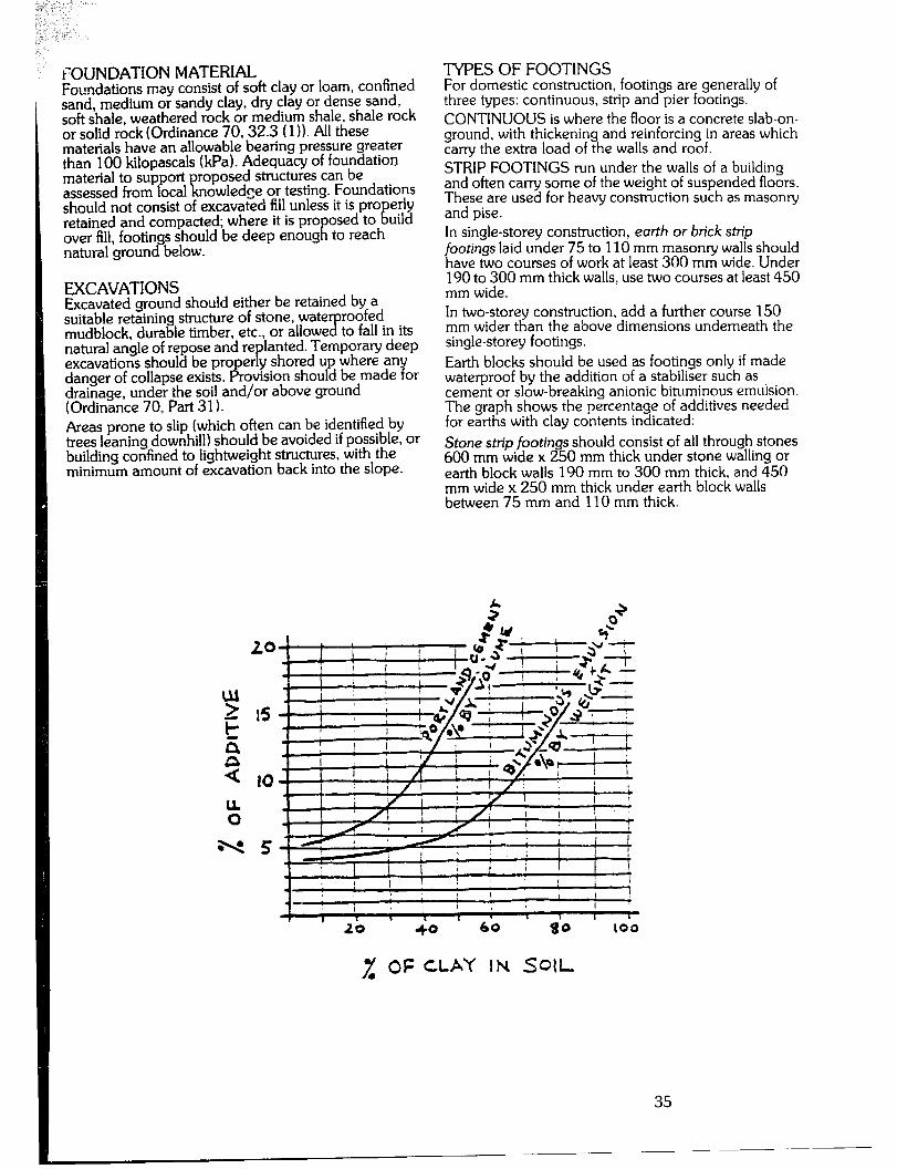
FOUNDATIONMATERIAL Foundations may consist of soft clay or loam, confined sand, medium or sandy clay, dry clay or dense sand. soft shale, weathered rock or medium shale, shale rock or solid rock (Ordinance 70,32.3 (1 I). All these materials have an allowable bearing pressure greater than 100 kilopascals (kPa). Adequacy of foundation material to support proposed structures can be assessed from local knowledge or testing. Foundations should not consist of excavated fill unless it is pro erly retained and compacted; where it is pro
F: osed to tii uild
over fill, footings should be deep enoug to reach natural ground below.
EXCAVATIONS Excavated ground should either be retained by a suitable retaining structure of stone, wate roofed mudblock, durable timber, etc., or allowe ‘B to fall in its natural angle of repose and re lanted. Temporary deep excavations should be proper y shored up where any P danger of collapse exists. Provision should be made for drainage, under the soil and/or above ground (Ordinance 70. Part 31). Areas prone to slip (which often can be identified by trees leaning downhill) should be avoided if possible, or building confined to lightweight structures, with the minimum amount of excavation back into the slope.
TYPESOFFOOTINGS For domestic construction, footings are generally of three types: continuous, strip and pier footings. CONTINUOUS is where the floor is a concrete slab-on- ground, with thickening and reinforcing in areas which carry the extra load of the walls and roof. STRIP FOOTINGS run under the walls of a building and often carry some of the weight of suspended floors. Thr;I;~ used for heavy construction such as masonry
In single-storey construction, earth or brick strip footings laid under 75 to 110 mm masonry walls should have two courses of work at least 300 mm wide. Under 190 to 300 mm thick walls, use two courses at least 450 mm wide. In two-storey construction, add a further course 150 mm wider than the above dimensions underneath the single-storey footings. Earth blocks should be used as footings only if made waterproof by the addition of a stabiliser such as cement or slow-breaking anionic bituminous emulsion. The graph shows the percentage of additives needed for earths with clay contents indicated: Stone strip footin s should consist of all through stones 600 mm wide x 3 50 mm thick under stone walling or earth block walls 190 mm to 300 mm thick, and 450 mm wide x 250 mm thick under earth block walls between 75 mm and 110 mm thick.
31 OF CLAY IN SOIL
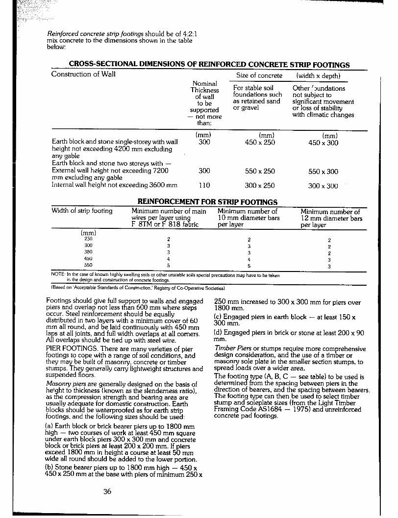
Reinforced concrete strip footings should be of 4:2:1 mix concrete to the dimensions shown in the table below:
CROSS-SECTIONAL DIMENSIONS OF REINFORCED CONCRETE STRIP FOOTINGS
Construction of Wall Size of concrete (width x depth) Nominal
Th$Far For stable soil Other !Jundations foundations such
to be as retained sand not subject to significant movement
supported or gravel or loss of stability - not more with climatic changes
than:
Earth block and stone single-storey with wall height not exceeding 4200 mm excluding any gable Earth block and stone two storeys with - External wall height not exceeding 7200 mm excluding any gable Internal wall height not exceeding 3600 mm
(mm) (mm) (mm) 300 450 x 250 450 x 300
300 550 x 250 550 x 300
110 300 x 250 300 x 300
REINFORCEMENT FOR STRIP FOOTINGS Width of strip footing Minimum number of main Minimum number of Minimum number of
~re.e.~;~ares;u85in%nc U.)r;;$ameter bars 12 mm diameter bars per layer
(mm) 230 2 2 2 300 3 3 2 380 3 3 2 450 4 4 3 550 5 5 3
- NOTE: In the case of known highly swelling soils or other unstable soils special precautions may have to be taken
in the design and construction of concrete footings.
(Based on ‘Acceptable Standards of Construction.’ Registry of Co-Operative Societies)
Footings should give full support to walls and engaged piers and overlap not less than 600 mm where steps occur. Steel reinforcement should be equally distributed in two layers with a minimum cover of 60 mm all round, and be laid continuously with 450 mm laps at all joints, and full width overlaps at all comers. All overlaps should be tied up with steel wire. PIER FOOTINGS. There are many varieties of pier footings to cope with a range of soil conditions, and they may be built of masonry, concrete or timber stumps. The generally carry lightweight structures and suspended oors. fr Moson y piers are generally designed on the basis of he!
% ht to thickness (known as the slenderness ratio),
as t e compression strength and bearing area are usually ade uate for domestic construction. Earth blocks shou d 7 be waterproofed as for earth strip footings, and the following sizes should be used: (a) Earth block or brick bearer piers up to 1800 mm high - two courses of work at least 450 mm square under earth block piers 300 x 300 mm and concrete block or brick piers at least 200 x 200 mm. If piers exceed 1800 mm in height a course at least 50 mm wide all round should be added to the lower portion. (b) Stone bearer piers up to 1800 mm high - 450 x 450 x 250 mm at the base with piers of minimum 250 x
36
Z~om~rmncreased to 300 x 300 mm for piers over
(cl Engaged piers in earth block - at least 150 x 300 mm. (d) Engaged piers in brick or stone at least 200 x 90 mm. Timber Piers or stumps require more corn
!I rehensive
design consideration, and the use of a tim er or mason spread ‘y
sole plate in the smaller section stumps, to oads over a wider area.
The footin determine 3
type (A, B, C - see table) to be used is from the spacing between piers in. the
direction of bearers, and the spacing between bearers. The footing type can then be used to select timber stump and soleplate sizes (from the Light Timber Framing Code AS1684 - 1975) and unreinforced concrete pad footings.
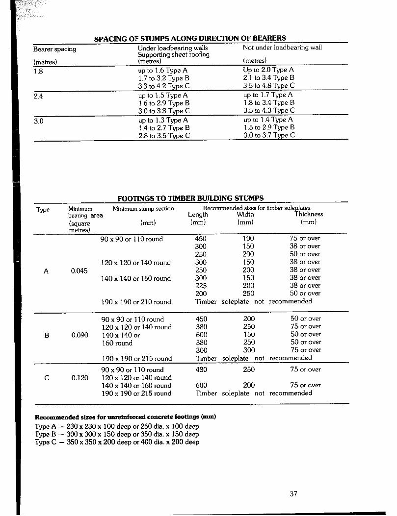
SPACING OF STUMPS ALONG DIRECTION OF BEARERS
I Bearer spacing Under loadbearing walls Not under loadbearing wall
fiuEiu;ing sheet roofing (metres)
1.8 up to 1.6 Type A Up to 2.0 Type A 1.7 to 3.2 Type B 2.1 to 3.4 Type B 3.3 to 4.2 Type C 3.5 to 4.8 Type C up to 1.5 Type A up to 1.7 Type A 1.6 to 2.9 Tvoe B 1.8 to 3.4 Type B 3.0 to 3.8 Type C 3.5 to 4.3 Type C upto 1.3TypeA up to 1.4 Type A 1.4 to 2.7 Type B 1.5 to 2.9 Type B 2.8 to 3.5 Type C 3.0 to 3.7 Type C
I FOOTINGS TO TIMBER BUJLDING STU: MPS
Me Minimum Minimum stump section bearing area
Recommende&r$;s for timber soleplates: Length Thickness
(square (mm) (mm) (mm) (mm) metres)
9Ox90orllOround 450 100 75 or over
A 0.045
300 150 38 or over 250 200 50 or over
120 x 120 or 140 round 300 150 38 or over 250 200 38 or over
140 x 140 or 160 round 300 150 38 or over 225 200 38 or over 200 250 50 or over Timber soleplate not recommended 190xl90or210round
B
C
0.090
0.120
9Ox90or 110round 120 x 120 or 140 round 140 x 140 or 160 round
190 x 190 or 215 round 90 x 90 or 110 round 120 x 120 or 140 round 140 x 140 or 160 round 190 x 190 or 215 round
450 200 50 or over 380 250 75 or over 600 150 50 or over 380 250 50 or over 300 300 75 or over Timber soleplate not recommended 480 250 75 or over
600 200 75 or ever Timber soleplate not recommended
Recommended sizes for unreinforced concrete footings (mm)
Type A - 230 x 230 x 100 deep or 250 dia. x 100 deep Type B - 300 x 300 x 150 deep or 350 dia. x 150 deep
deep or 400 dia. x 200 deep
37
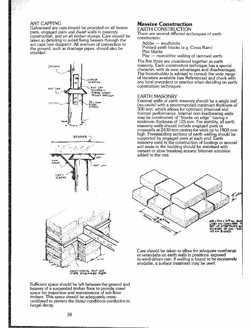
ANT CAPPING Galvanised ant caps should be provided on all bearer
assive Construction piers, engaged piers and dwarf walls in masonry EARTH CONSTRUCTION construction. and on all timber stumps. Care should be There are several different techniques of earth taken in detailing to avoid fixing bearers through the construction: ant caps (see diagram). All avenues of connection to the ground. such as drainage pipes, should also be shielded
Adobe - mudbricks Pressed earth blocks (e.g. Cinva Ram) Pise blocks Pise - monolithic walling of rammed earth.
The first three are considered together as earth masonry. Each construction technique has a special character, with its own advantages and disadvantages. The homebuilder is advised to consult the wide range of literature available (see References) and check with any local precedent or practice when deciding on earth construction techniques.
BEhRER -)
CON,-lNUO’& !WT c4P OCR ENdA’% PIER
Sufficient space should be left between the ground and bearers of a suspended timber floor to provide crawl space for inspection and maintenance of sub-floor timbers. This space should be adequately cross- ventilated to prevent the damp conditions conducive to fungal decay.
38
EARTH MASONRY External walls of earth masonry should be a single leaf (no cavity) with a recommended minimum thickness of 300 mm. which allows for optimum structural and thermal performance. Internal non-loadbearing walls may be constructed of “blocks on edge” havin
B a
minimum thickness of 125 mm. For stability, al earth masonry walls should include engaged piers or crosswalls at 2400 mm centres for work up to 1800 mm high. Freestanding sections of earth walling should be supported by engaged piers at each end. Earth masonry used in the construction of footings or around wet areas in the building should be stabilised with cement or slow breaking anionic bitumen emulsion added to the mix.
Care should be taken to allow for adequate overhangs or verandahs on earth walls in positions exposed to wind-driven rain. If walling is found to be excessively erodable, a surface treatment may be used.
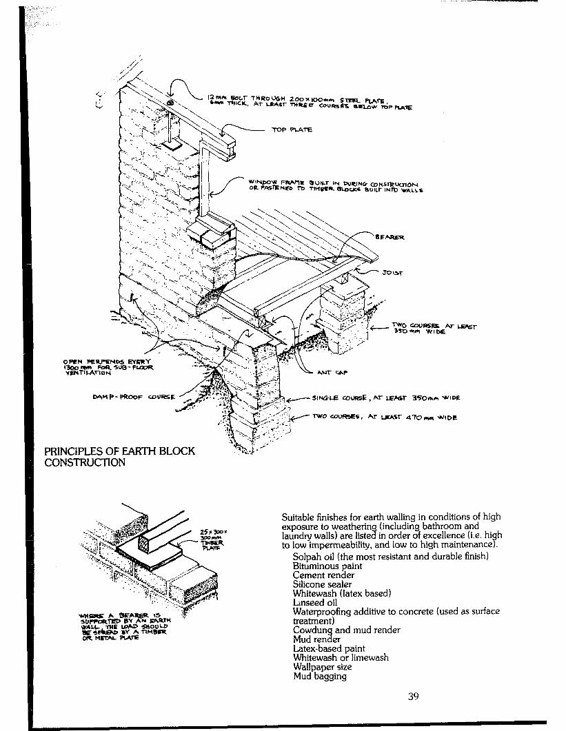
-
SWGLE COURSE , AI- l.EhW 35Omrh WlW
PRINCIPLES OF EARTH BLOCK CONSTRKTION
Suitable finishes for earth walling in conditions of high exposure to weatherin laundry walls) are liste %
(including bathroom and in order of excellence (i.e. hi
to low impermeability, and low to high maintenance s h .
Solpah oil (the most resistant and durable finish) Bituminous paint Cement render Silicone sealer Whitewash (latex based) Lnseed oil Waterproofing additive to concrete (used as surface treatment) Cowdun and mud render Mud ren % er Latex-based paint Whitewash or limewash Wallpaper size Mud bagging
39
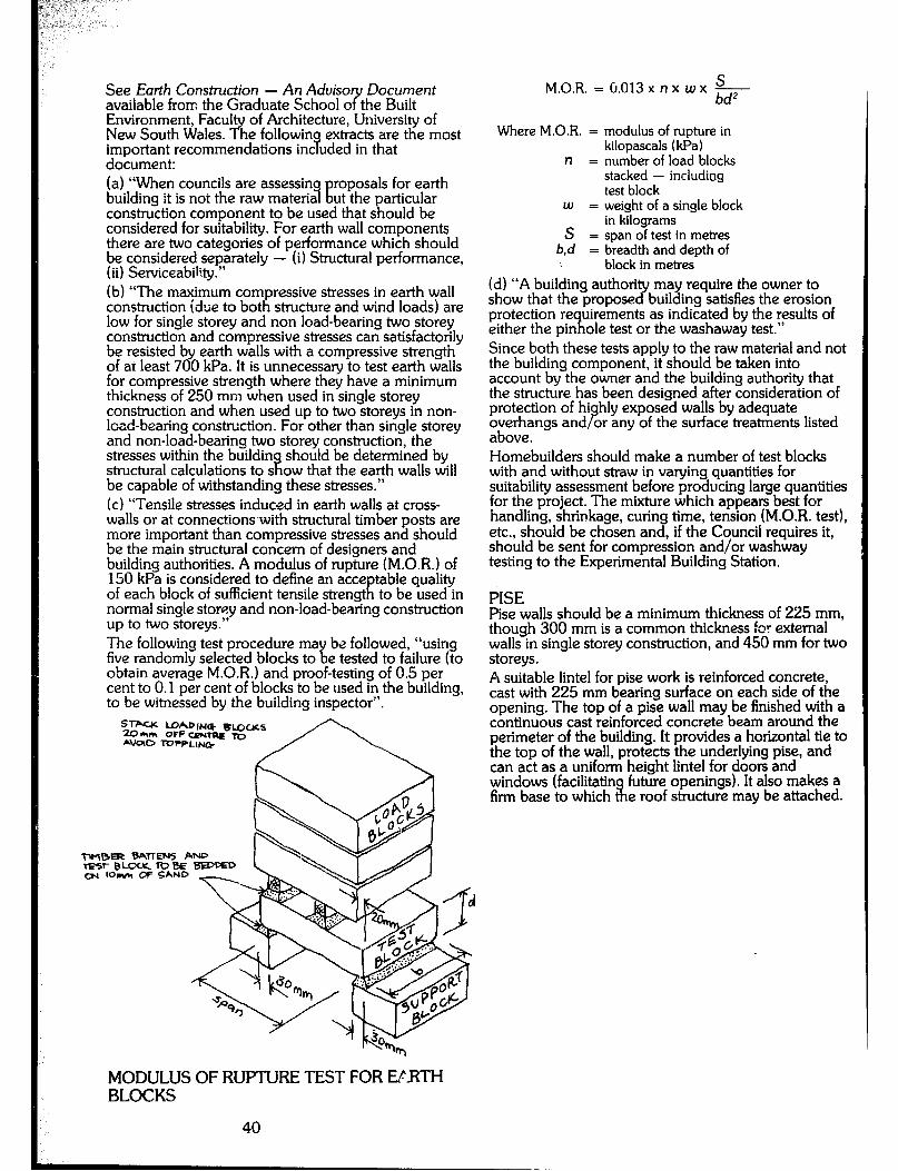
See Earth Construction - An Advise Document available from the Graduate School o iy the Built Environment, Facul New South Wales. ?
of Architecture, University of he followin extracts are the most
important recommendations inc uded in that H document: (a) “When councils are assessing building it is not the raw material !I
roposals for earth ut the particular
construction component to be used that should be considered for suitability. For earth wall components there are two categories of performance which should ;; y;;.g!gy?*te’y - (i) Structural performance,
(b) “The maximum compressive stresses in earth wall construction idue to both structure and wind loads) are low for single storey and non load-bearing two storey construction and compressive stresses can satisfactorily be resisted by earth walls with a compressive strength of at least 700 kPa. It is unnecessary to test earth walls for compressive strength where they have a minimum thickness of 250 mm when used in single storey construction and when used up to two storeys in non- load-bearing con . strdction. For other than single storey and non-load-bearing two storey construction, the stresses within the buildin structural calculations to s a
should be determined by ow that the earth walls will
be capable of withstanding these stresses.” (c) “Tensile stresses induced in earth walls at cross- walls or at connections.with structural timber posts are more important than compressive stresses and should be the main structural concern of designers and building authorities. A modulus of rupture (M.O.R.) of 150 kPa is considered to define an acce of each block of sufficient tensile strengt i:
table quality to be used in
normal single storey and non-load-bearing construction up to two storeys.” The following test procedure ma five randomly selected blocks to t:
be followed, “using e tested to failure (to
obtain average M.O.R.) and proof-testing of 0.5 per cent to 0.1 per cent of blocks to be used in the building, to be witnessed by the building inspector”.
S M.O.R. = (~013 x n x w x - bd*
Where M.O.R. = modulus of rupture in kilopascals (kPa)
n = number of load blocks stacked - including test block
W = weight of a single block
S in kilograms
= span of test in metres b,d = breadth and depth of
block in metres (dl “A building authori show that the propose 2
may require the owner to building satisfies the erosion
protection re uirements as indicated by the results of either the pin 9, ole test or the washaway test.” Since both these tests apply to the raw material and not the building component, it should be taken into account by the owner and the building authority that the structure has been designed after consideration of protection of hi overhangs and B
hly exposed walls by adequate
above. or any of the surface treatments listed
Homebuilders should make a number of test blocks with and without straw in vaying quantities for suitability assessment before producing large quantities for the project. The mixture which appears best for handling, shrinkage, curing time, tension (M.O.R. test), etc., should be chosen and, if the Council requires it, should be sent for compression and/or washway testing to the Experimental Building Station.
PISE Pise walls should be a minimum thickness of 225 mm, though 300 mm is a common thickness for external walls in single storey construction, and 450 mm for two storeys . A suitable lintel for pise work is reinforced concrete, cast with 225 mm bearing surface on each side of the opening. The top of a pise wall may be finished with a continuous cast reinforced concrete beam around the perimeter of the building. It provides a horizontal tie to the top of the wall, protects the underlying pise, and can act as a uniform height lintel for doors and windows (facilitatin firm base to which 3l
future openings). It also makes a e roof structure may be attached.
MODULUSOFRUPIlJRETESTFORElRTH BLOCKS
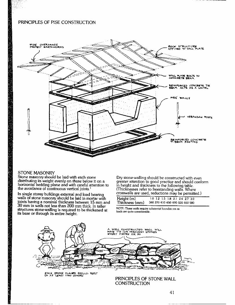
PRINCIPLES OF PISE CONSTRUCTION
ROOF SlRULTUaC /-AFFI*rc, TO W&U PGE WIPE OVERHANGS t=wmT EARTHWORKS
‘.... .‘....__.
++-...3
WALLPLATEWOUSW eDNCREl-E BEAk.
INFOCKED CONCREE 8EAl-l FOOTI “r*
STONE MASONRY Stone masonry should be laid with each stone distributing its weight evenly on those below it on a horizontal bedding plane and with careful attention to the avoidance of continuous vertical joints.’ In single storey buildings external and load bearing walls of stone masonry should be laid in mortar with joints having a nominal thickness between 15 mm and 30 mm in walls not less than 200 mm thick. In taller structures stone-walling is required to be thickened at its base or through its entire height.
Dry stone-walling should be constructed with even greater attention to good practice and should conform in height and thickness to the following table. (Thicknesses refer to freestanding walls. Where crosswalls are used, reductions may be permitted.) Height (m) 1.0 1.2 1.5 1.8 2.1 2.4 2.7 3.0
Thickness (mm) 340 370 410 450 490 520 550 580
NOTE: These walls require substantial foundat) ms as loads are quite considerable.
EACH STONE PUKED SYou~n Q?5.l- ON AT LEASf Two oTltEl?S
PRINCIPLES OF STONE WALL CONSTRUCTION
41

ou1
BOI-I-LE MASONRY Glass bottles may be used as a trarslucent, non- loadbearing infill wall. Bottles should be clean, and laid with the necks pointing outwards, bedded in a 5:l sand/cement mix. A minimum of mortar should be used, and excess should be cleaned off the bases as they are laid. Wire reinforcement is used every six courses to tie the wall into surrounding load-bearing structures.
6elCK COURSING *ID EVeRY SIX CODR6E5, TED ml.0 COLU
MORTARS IN MASONRY CONSTRUCTION The following mortars may be used: 1) Mud mortar for earth block construction consisting of earth mixed with water, free from organic matter and sieved to remove stones, can be used above damp-
T roof course level. For work below damp proof course
eve1 add one part Portland cement to nine parts earth. Earth used in mortar should have a clay content between 25 er cent and 50 per cent; sand may be added to re B uce clay content. Mortar joints in earth masony should have a minimum thickness of 25 mm. 21 Cement mortar for stone and brick masonry below damp proof course level should consist of one part cement to six parts sand. Above this level use a mix of two parts cement to nine parts sand. 31 Compo mortar for stone and brick masonry: add one i;cv2drated lime to the cement mortar mixtures
42
DAMP-PROOFING OF MASONRY WALLS Dam
P -proofing of lead, bituminous coated non-ferrous
meta s, pol Ordinance Y
hene or other suitable material (refer to 0, S
built into all cart E ecification 5, part 47,l O(a)) should be and stone mason at a hei ht not
less than 150 mm above the finishe K ground P eve!. Sheet materials should be lapped 100 mm at joints. To earth or stone masonry walls surrounding solid floors, bathrooms, shower rooms, laundries, etc., an additional damp proof course should be built in one course above floor level and be dressed down to cover the edges of the damp proof membrane under the solid floor.
PRINClPLES OF BOI-I-LE WALL CONSTRUCTION
DAMP PROOFING OF WET-AREA FLOORS
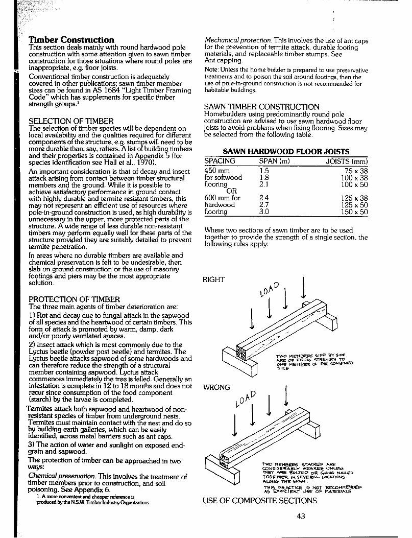
Timber Construction This section deals mainly with round hardwood pole construction with some attention iven to sawn timber construction for those situations w 3, inappropriate, e.g. floor joists.
ere round poles are
Conventional timber construction is adequately covered in other publications; sawn timber member sizes can be found in AS 1684 “Light Timber Framing Code” which has supplements for specific timber strength groups.’
SELECTION OF TIMBER The selection of timber species will be dependent on local availabili
? and the qualities required for different
components o the structure, e.g. stum s will need to be more durable than, say, rafters. A list o P buildin timbers and their properties is contained in Appendix % (for species identification see Hall et al., 1970). An important consideration is that of decay and insect attack arising from contact between timber structural members and the ground. While it is possible to achieve satisfactory performance in ground contact with highly durable and termite resistant timbers, this may not represent an efficient use of resources where pole-in-ground construction is used, as high durability is unnecessary in the upper, more protected parts of the structure. A wide range of less durable non-resistant timbers may perform equally well for these arts of the structure provided they are suitably detaile cf to prevent termite penetration. In areas where no durable timbers are available and chemical preservation is felt to be undesirable, then slab on ground construction or the use of masonry footings and piers may be the most appropriate solution.
PROTECTION OF TIMBER The three main agents of timber deterioration are: 1 I Rot and deca of all species an d
due to fungal attack in the sapwood the heartwood of certain timbers. This
form of attack is promoted by warm, damp, dark and/or poorly ventilated spaces. 2) Insect attack which is most commonly due to the Lyctus beetle (powder post beetle) and termites. The Lyctus beetle attacks sapwood of some hardwoods and can therefore reduce the stren h of a structural member containin commences imme 3
sapwood. i! yctus attack iately the tree is felled. Generally an
infestation is ccmplete in 12 to 18 months and does not recur since consumption of the food component (starch) by the larvae is completed.
Termites attack both sapwood and heartwood of non- resistant species of timber from underground nests. Termites must maintain contact with the nest and do so b i J
building earth gaileries, which can be easily entified, across metal barriers such as ant caps.
3) The action of water and sunlight on exposed end- grain and sapwood. The protection of trmber can be approached in two ways: Chemicd preservation. This involves the treatment of timber members prior to construction, and soil poisoning. See Appendix 6.
1. A more anvenient and cheaper refettme is produced by the N.S.W. liiber Induty Ckgdwion~.
Mechanical protection. This involves the use of ant caps for the prevention of termite attack, durable footing materials, and replaceable timber stumps. See Ant capping. Note: Unless the home builder is prepared to use presewative treatments and to poison the soil around footings, then the use of pole-in-ground construction is not recommended for habitable buildings.
SAWN TIMBER CONSTRUCTION Homebuilders using predominantly round pole construction are advised to use sawn hardwood floor joists to avoid problems when fixing flooring. Sizes may be selected from the following table.
SAWN HARDWOOD FLOOR JOISTS SPACING SPAN (m) JOISTS (mm) 450 mm 75x38 for softwood 2 100x38 flooring 2.1 100x50
OR 600 mm for 2.4 125x38 hardwood 2.7 flooring 3.0 EiEi
Where two sections of sawn timber are to be used together to provide the strength of a single section. the following rules apply:
RIGHT
‘Iwo IIEHB~ ~.liilED hQE WNSIDERA~Y WEAUE~ ClNceU ‘Tb+‘D A- 8OUXD OR *AN& NAIUZD TOWlItER IM SEVERAL WWTIONS hl.DN& THE SPAN.
THIS P YTI’E IS Mit- RfXdlH~DEP AS EPFlC EMT USE OF t’-lATmlAkS
USE OF COMPOSITE SECTIONS
43
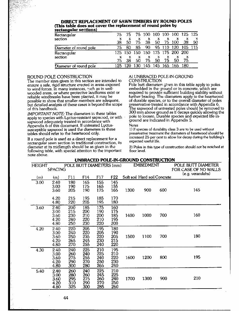
DIRECT REPLACEMENT OF SAWN TIMBERS BY ROUND POLES (This table does not cover the replacement of round poles by rectangular sections) Rectangular 75 75 75 100 100 100 100 125 125 section-
38x 5; 7; 3; 5;; 75x 10; 3; 5;; Diameter of round pole 75 80 85 90 95 110 120 105 115 Rectangular 125 150 150 150 175 175 200 200 section-
7; 3; 5; 7; 50” 7; 5; 7: Diameter of round pole 125 120 130 145 145 165 165 180
ROUND POLE CONSTRUCTION The member sizes given in this section are intended to ensure a safe, rigid structure erected in areas exposed to wind forces. In many instances, ruch as in well- wooded areas, or where protective landforms exist or reliable windbreaks have been planted, it may be
E ossible to show that smaller members are adequate, ut detailed analysis of these cases is beyond the scope
of th;s handbook. IMPORTANT NOTE: The diameters in these tables apply to species with Lyctus-resistant sapwJod, or with sapwood ade uately treated in accordance with Appendix 6 o this document. If untreated Lyctus- 9 susceptible sapwood is used the diameters in these tables should refer to the heartwood only. If a round pole is used as a direct replacement for a rectangular sawn section in traditional construction, its diameter at its midlength should be as given in the following table, with special attention to the important note above.
A) UNBRACED POLE-IN-GROUND CONSTRUCTION Pole butt diameters #en in this table apply to poles embedded in the ground or in concrete, which are required to provide sufficient building stability without further bracing. The diameters apply to the heartwood of durable species, or to the overall diameter of poles
reservative-treated Y
in accordance with Appendix 6. he sapwood of untreated poles should be removed to
300 mm above pole to loosen. B
ound as it decays quickly allowing the urable species and expected Iife-in-
ground are indicated in Appendix 5. Notes 1) If species of durability class 3 are to be used without preservative treatment the diameters of heartwood should be increased 2.5 per cent to allow for decay during the building’s expected useful life.
2) Poles in this type of construction should not be notched at floor level.
UNBRACED POLE-IN-GROUND CONSTRUCTION HEIGHT POLE BUTT DIAMETERS (mm) EMBEDMENT POLE BUT-I DIAMETER
SPACING FOR CASE OF NO WALLS
(ml (ml Fll F14 F17 F22 Soft soil Hard soil Concrete (e.g. verandahs)
3.00 2.40 180 165 155 145 3.00 190 175 165 155 3.60 205 190 175 165 1300 900 600 145
4.20 ;;z 195 185 170 4.80 205 195 180
3.60 2.40 200 185 160 3.00 215 200 3 *-PI- 3.60 230 210 4.20
;z: 220
4.80 230
IYU l/3 200 185 1400 1000 700 160 210 195
4.20 2.40 220 205 3.00 240 220 3.60 4.20 E E 4.80 270 255
4.30 2.40 240 3.00 260 ;:z +a& 5;; 255
4:80 300 z 5.40 2.40 Ez 240
3.00 260
220 %a 195
;!iz %
E 1500 1100 700 180
% 220 E 195
240 E 1600 1200 800 195
250 265 z: E 210
260 1700 1300 900 210 p& 4:80
E E 325 300 285 260
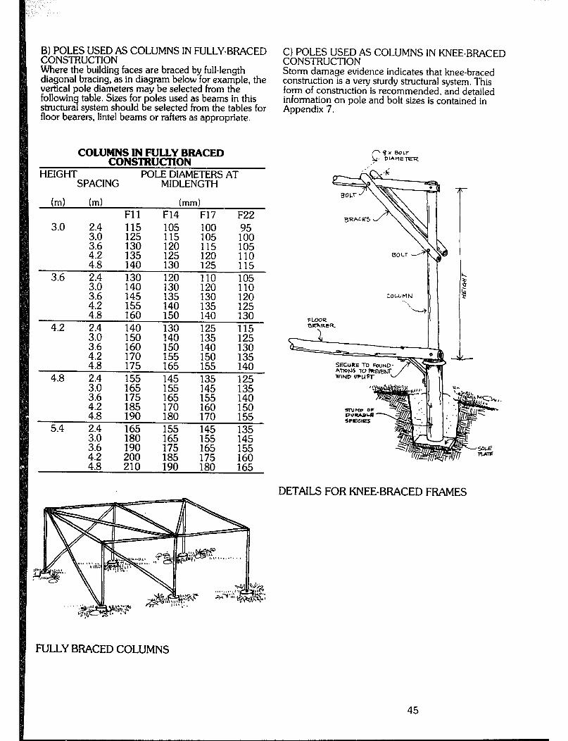
B) POLES USED AS COLUMNS IN FULLY-BRACED CONSTRUCTION
C) POLES USED AS COLUMNS 1N KNEE-BRACED CONSTRUCTION
Where the building faces are braced by full-length diagonal bracing, as in diagram below for example, the vertical pole diameters may be selected from the followin table. Sizes for poles used as beams in this structura system should be selected from the tables for 7 floor bearers, lintel beams or rafters as appropriate.
Storm damage evidence indicates that knee-braced construction is a very sturdy structural system. This form of construction is recommended, and detailed information on pole and bolt sizes is contained in Appendix 7.
COLUMNS IN FUUY BRACED CONSTRUCTION
HEIGHT POLE DIAMETERS AT SPACING MIDLENGTH
hd (ml (mm) Fll F14 F17 F22
3.0 115 105 100 95 125 105 130 ::z 115 E
4.2 E 125 :;50 110 4.8 130 115
3.6 ::i 130 110 140 % 120 17: E
4:8
:“;z :z 130 120
160 150 E 2;
4.2 :*;t 140 130 125 3:6 E 150 140 135 140
::; 130
::i 170 175 E 150 155 :3;
4.8 E 155 145 135 145 2: g . :;2 E 22 :2i 2: 170 E 140
5.4 $2 165
:iz E 1:; E 175 155
t :i 210 200 :Ei E 180 E
1 h 4
COLUMN e
---\
FLOOR I DEXRER
/I I
DETAILS FOR KNEE-BRACED FRAMES
F'ULLYBFACEDCOLUMNS

~&IF’O~ES USED AS EAVES BEAMS AND RIDGE
If an eaves beam or ridge beam is used in a structure supported at each end and not knee-braced as in section C, its size should be selected from the following table:
EAVES, BEAMS AND RIDGE BEAMS Pole diameters at midspan (mm)
v up to 3.0 Spacin s (ml
m 3.z 4.2 - - . -- *m- l “F 125 3.6 145 133
6.0 210
E) POLES USED AS FLOOR BEARERS The sizes for round selected from the
oles used as floor bearers may be fo lowing table. P
Ting Bearers
FLOOR BEARERS Bearer diameter at midspan
Spans (metres)
1.8 2.1 2.4 2.7 3.0 3.3 3.6 3.9 4.2 1.8 105 115 125 135 150 160 170 185 200 2.4 110 120 140 150 165 175 190 200 210 3.0 120 130 150 155 175 185 200 215 225
DEl?AlL OF BEArt COLUtlN fUNCT ION !‘kToRE AlTAcH tW-‘r OF 1-It-wBER p-l-m (SIZE DIAG+W+ LB~)
JOINT DETAILS FOR ROUND POLE BEARERS
46

F) POLES USED AS RAFTERS OR PURLINS Pole diameters at midlength for use as rafters or purlins may be selected from the following table. These member sizes are suitable for sheet galvanised steel roofing with or without timber lining. Particular attention must be aid to enstire that the roof is held down against win s uplift. Strapping is recommended.
RARER & PURLIN SIZES Pole diameters at midspan (mm)
Spacing of rafters or Spans (ml purlins (mm) UP to2.1 2.4 3.0 3.6 4.2 4.8
450 or 6UO 75 80 90 105 120 130 900 75 85 95 110 125 135
1200 80 85 100 115 130 140 1500 80 90 105 120 135 150 1800 85 95 110 125 140 155 2100 90 95 115 130 145 160
IS &AU&E GA LVAwlZED STE6L STRAP OVER
FIXING OF RAFTERS TO BEAM
ROUNDPOLES MEMBERS
USED AS STRUCTURAL.
STEEL STU4P TO COUNTER END SPLlTlNG
SLOPl!uG cur l-0 CwCn 4Tw.SE OF CoLUithl
CRECKING AI- SIDE OF DEA~R SltOULD BE MIN~YAL SUFFICIENT To 65r4suslH lw=4RlN4 SURFArE ~El-WEEh’ WLUHN AND DEARER

G) POLES USED AS ROOFING BATTENS Pole diameters at midlength for use as battens may be selected from the following table. These sizes are suitable for use with sheet roofing with or without timber lining. Particular attention must be paid to ensuring the battens are held down against wind uplift.
ROOFING BATlENS
spacing of
b?:z 330
(for tiled roof) 450 600
Batten diameter F5r of barn fraa; sp;;&g)
30 30 35 45
30 30 35 45 30 35 35 45
906 35 35 40 45 1200 35 35 45 50
Strapping as shown for rafters is recommended. If s ans for battens are required to be greater than 1280 mm, use diameter given in table above for purlins.
TESTING FOR STRUCTURAL ADEQUACY OF UNUSUAL TIMBER STRUCTURES There are three main types of loading which may be applied to a structure. These load types are: - The self weight of the building, called dead load - Applied loads due to the use of the building, e.g. people and furniture, called live load - Applied loads due to wind, called wind load The load types can act in combination with each other. The following are the usual combinations: - Dead load - Dead load and live load - Dead load and wind load - Dead !oad and live load and wind load Each of the load combinations is called a load case, For most practical situations the following load cases are sufficient: 1) Dead load and live load on floors 2) Dead load and wind load on roof 3) Wind load on walls Test load magnitudes for these cases are as follows.
DEAD LOAD PLUS WIND LOAD ON ROOF In most cases this loading combination gives a suction or lifting effect. It will be satisfacto to test it as with a downward load plus a careful chec 7 on joints holding down the roof to the building. In practically all cases it will be impossible to apply the load upwards - the upward load would lift most buildings, The magnitude of the test ioadin is 1.75 kN/m2 measured on horizontal surface. i! he load should be applied for 15 minutes. Note that it must be removed quickly after the 15 minutes have elapsed.
WIND LOAD ON WALLS The magnitude of the test loading is 2.5 kN/m2. The load should be applied for 15 minutes. Note that it must be removed quickly after 15 minutes have elapsed.
COMMENTS 1) The test loadings involved are very large. When settin (I&
up a load test the ability to remove the load
s or.11 from the structure (say within 30 minutes) be considered. As a rough guide the material
concrete weighs 24 kN/m3, water weighs 9.7 kN/m3, dy sand weighs 15 kN/m3 clay bricks weigh 18 kN/m3, clay weighs 15 kN)m3. (A 17 stone person weighs approximately 1 kN.1 These weights are approximate. 2) Load cases 2 and 3 (Dead load and wind load on roof; Wind load on walls) occur together when the wind blows. However, it is very difficult to achieve this in a test. 3) In the case of roof tests the load of 1.75 kN/m2 should be applied over the whole roof and then the ;h2;tu;r tested again with 1.75 kN/m2 applied to half
4) Under severe wind load conditions it is possible for light timber structures to be lifted off their supports. This problem is best avoided by ensuring that the roof structure is adequately anchored down through the walls to the ground.
DEAD LOAD PLUS LIVE LOAD ON FLOORS The magnitude of the test loading is 5.5 kN/m2 (five and a half kilonewtons should be applied for 1 !!i
er square metre). This load minutes. Note that it must be
removed quickly after the 15 minutes have elapsed.
48
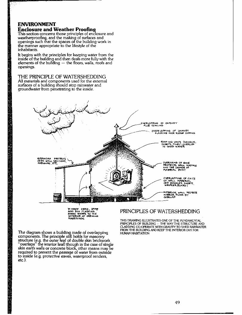
ENVIRONMENT Enclosure and Weather Proofing This section concerns those principles of enclosure and weatherproofin , and the makin of surfaces and openings such t 9, at the spaces o P the building work in the manner appropriate to the lifestyle of the inhabitants. It begins with the principles for keeping water from the inside of the building and then deals more fully with the elements of the building - the floors, walls. roofs and openings.
THE PRINCIPLE OF WATERSHEDDING All materials and components used for the external surfaces of a building should stop rainwater and groundwater from penetrating to the inside.
7. OUERtMPING OP tnlMtin l IASHING OYER R~cG@ GV’PIN&
RO’JFING Ut41l-S kHlrlGG5, SHBrS,TlLES~ O\lERLAP TO SHED \H’ArER
VERANDAH OWJ-4 WALL SECTIONS OPENlN45, ETL
OVtRI+ANC* OF ~Avt =#-k?cl% WALL SlJRFe t.un TIF: PYIWP~ d
I -.-- a.-C -- “l t’%WlFRIAL IDINT
O\rERL(APPlruf CF UNlB OF WALL PVUtSJAL e* SHlrJfiLEI, sum, WFAIYCRBOARD)
SrreRIOQ WALL PUOrM
WINDOW H-D Jrklb MD SIU FLASifNG SHRDS WATER TO THE
PRINCIPLES OF WATERSHEDDING
The diagram shows a building made of overlapping components. The princi structure (e.
le still holds for masonry . the outer eaf of double skin brickwork
THIS DRAWING ILLUSTRATES ONE OF THE FUNDAMENTAL PRINCIPLES OF BUILDING - THE WAY THE STRUCTURE AND CLADDING CO-OPERATE WITH GRAVIIYTO SHED RAINWATER ‘==tOM THE BUILDING AND KEEP THE INTERIOR DRY FOR
UMAN HABITATION
“overlaps” tf P
e interior leaf) though in the case of sin le skin earth walls or concrete block, other means may % e required to prevent the passage of water from outside to inside (e.g. protective eaves, waterproof renders, A,\
i-i
49
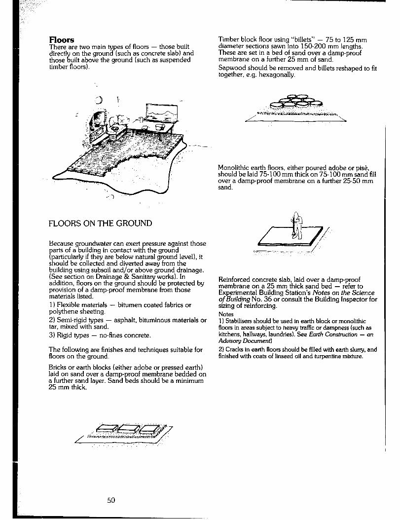
Floors There are two main types of floors - those built direct! on the ground (such as concrete slab) and those E uilt above the ground (such as suspended timber floors).
FLOORS ON THE GROUND
Because groundwater can exert ressure against those
P arts of a building in contact wit R the ground particularly if they are below natural ground level), it
should be collected and diverted away from the building using subsoil and/or above ground drainage. (See section on Drainage & Sanita works). In addition, floors on the ground shou d be protected by 7 provision of a damp-proof membrane from those materials listed. 1) Flexible materials - bitumen coated fabrics or polythene sheeting. 2) Semi-rigid types - asphalt, bituminous materials or tar, mixed with sand. 3) Rigid types - no-fines concrete.
The following are finishes and techniques suitable for floors on the ground. Bricks or earth blocks (either adobe or pressed earth) Iaid on sand over a damp-proof membrane bedded on a further sand layer. Sand beds should be a minimum 25 mm thick.
Timber block floor using “billets” - 75 to 125 mm diameter sections sawn into 150-200 mm lengths. These are set in a bed of sand over a damp-proof membrane on a further 25 mm of sand. Sapwood should be removed and billets reshaped to fit together, e.g. hexagonally.
Monolithic earth floors, either should be laid 75- 100 mm thic K
oured adobe or pi&, on 75- 100 mm sand fill
over a damp-proof membrane on a further 25-50 mm sand.
Reinforced concrete slab, laid over a damp-proof membrane on a 25 mm thick sand bed - refer to Experimental Building Station’s Notes on the Science of Building No. 36 or consult the Building Inspector for sizing of reinforcing. Notes 1) Stabilisen should be used in earth block or monolithic floors in areas subject to heavy tmffic or dampness (such as kitchens, hallways, laundries). See Earth Construction - an Aduiso y Document)
2) Cracks in earth floors should be filled with earth sluny, and finished with coats of linseed oil and turpentine mixture.
50
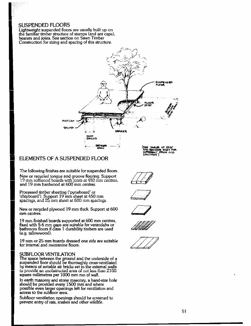
SUSPENDED FLOORS Lightweight suspended floors are usually built up on the familiar timber structure of stumps iand ant caps), bearers and joists. See section on Sawn Timber Construction for sizing and spacing of this structure.
ELEMENTS OF A SUSPENDED FLOOR
The following finishes are suitable for suspended floors. New or recycled tongue and groove flooring. Support 19 mm softwood boards with joists at 450 mm centres, and 19 mm hardwood at 600 mm centres.
Processed timber sheeting (‘pyneboard’ or ‘chipboard’). Su port 19 mm sheet at 450 mm spacings, and 2 !! mm sheet at 600 mm spacings.
New or recycled plywood 19 mm thick. Support at 600 mm centres.
19 mm finished boards supported at 600 mm centres, &ced with 5-6 mm aps are suitable for verandahs or bathroom floors if c ass 9 (e.g. tallowwood).
1 durability timbers are used
19 mm or 25 mm boards dressed one side are suitable for internal and mezzanine floors.
SUBFLOOR VENTllATlON The space between the ound
i? and the underside of a
suspended floor should e thoroughly cross-ventilated by means of suitable air bricks set in the external walls to provide an unobstructed area of not less than 2100 square millimetres per 1000 mm run of wail. In earth masonry and stone masony, a hand-size hole should be provided every 1500 mm and where possible even lar access to the sub
er openings left for ventilation and i oor area.
Subfloor ventilation openings should be screened to prevent entry of rats, snakes and other wildlife.
., 0 : “.C ,,
51
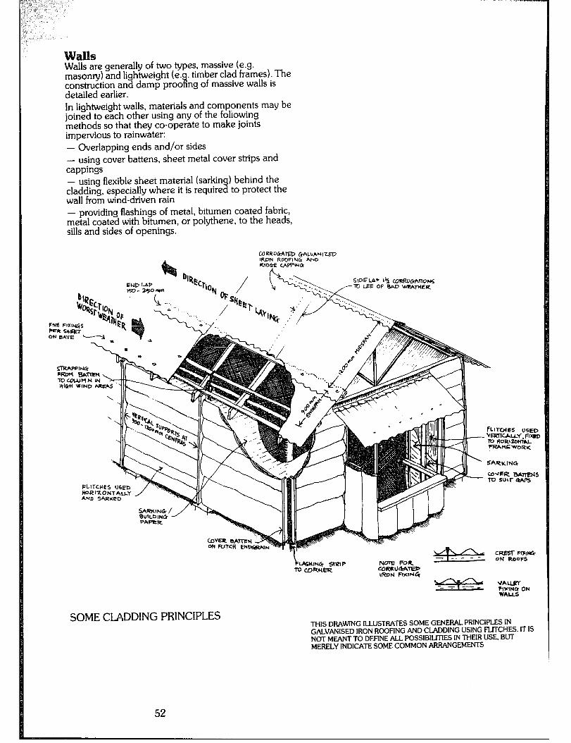
alls Walls are generally of two types, massive (e.g. masonry) and lightweight (e.
w . timber clad frames). The
construction and damp proo ng of massive walls is detailed earlier. In lightweight walls, materials and components may be joined to each other using any of the following methods so that they co-operate to make joints impervious to rainwater: - Overlapping ends and/or sides - using cover battens, sheet metal cover strips and cappings - using flexibie sheet material (sarking) behind the cladding, especially where it is required to protect the wall from wind-driven rain - providing flashings of metal, bitumen coated fabric, metal coated with bitumen, or polythene, to the heads, sills and sides of openings.
END 1.4P SIDEL~P 1% LORRuCrhnoNS
ED- 25OW TO LEE OF BAD ‘U?AWEU
-R SHQT ON UYE w
mrcI4Es “SE0 w%znc.Au~, Pwx TV HORIZONV,L FM WORU
FLITCUES NED H~RIZOHT~UY AND ‘%RKED
SOME CLWD!NG PRINCIPLES THIS DRAWING ILLUSTRATES SOME GENERAL PRINCIPLES IN GALVANISED IRON ROOFING AND CLADDING USING FLITCHES. IT IS NOT MEANT TO DEFINE ALL POSSIBILITIES IN THEIR USE, BUT MERELY INDICATE SOME COMMON ARRANGEMENTS
52
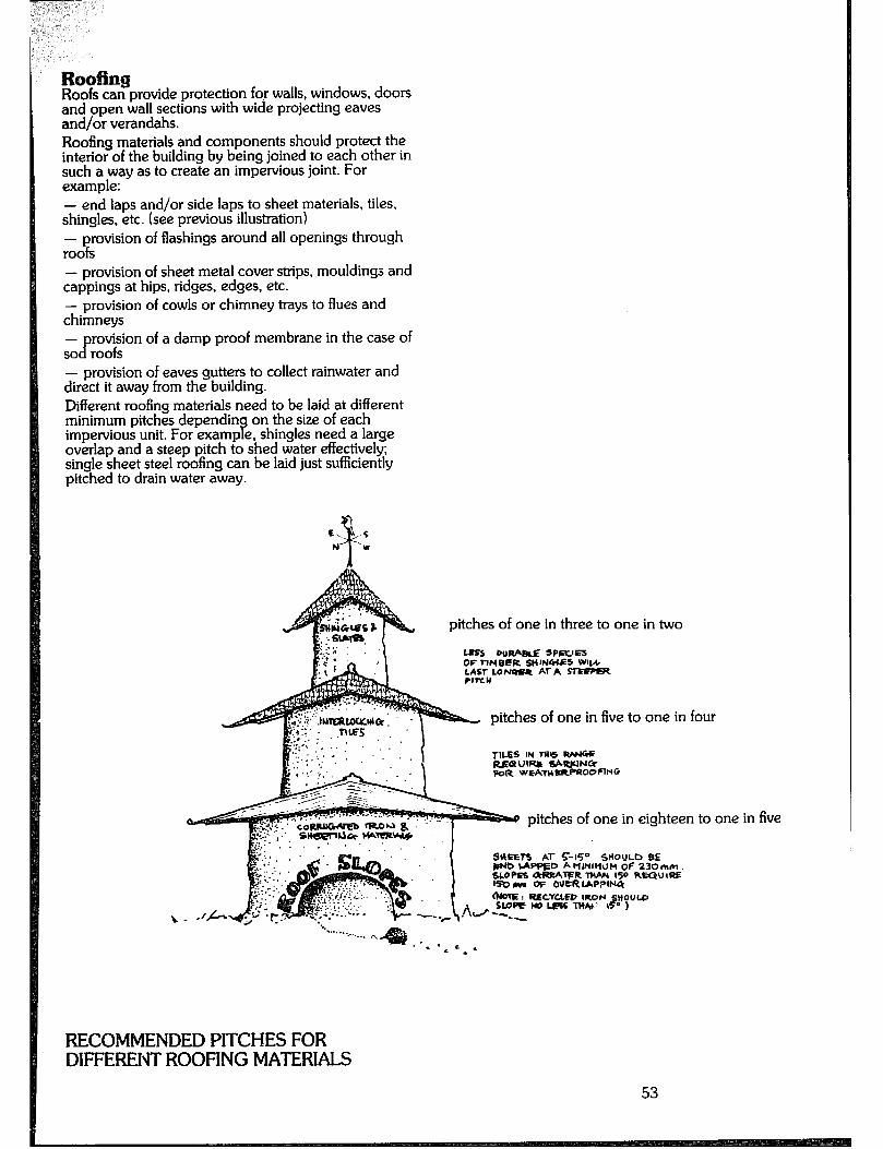
car?provide protection for walls, windows, doors and open wall sections with wide projecting eaves and/or verandahs. Roofing materials and components should protect the interior of the building by being joined to each other in such a way as to create an impervious joint. For example: - end laps and/or side laps to sheet materials, tiles, shingles, etc. (see previous illustration) - provision of flashings around all openings through roofs - provision of sheet metal cover strips, mouldings and cappings at hips, ridges, edges, etc. - provision of cowls or chimney trays to flues and chimneys -
CT rovision of a damp proof membrane in the case of
so roofs - provision of eaves gutters to collect rainwater and direct it away from the building. Different roofing materials need to be laid at different minimum pitches dependin on the size of each impervious unit. For examp e, shingles need a large 8 overlap and a steep pitch to shed water effectively; single sheet steel roofing can be laid just sufficiently pitched to drain water away.
pitches of one in three to one in two
lss wwauE SPRYEI OF ?-IHOI?R SHW4LES WW
pitches of one in five to one in four
TILES IY TRlS WNtc RIiaUlfW tiWUNCI FOR w~~ERPROD~ING
pitches of one in eighteen to one in five
SWEEl5 Al- C-15” SHOULD SE WO LAPPED A WINWJH OF 230hm
RECOMMENDED PITCHES FOR DIFFERENT ROOFING MATERIALS
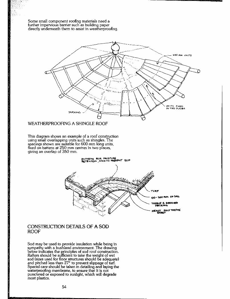
Some small component roofing materials need a further impervious barrier such as buildin directly underneath them to assist in weat 7l
paper erproofing.
UN 11-5 FIXED IN TWO PLACES
sAqKl% Yy&
WEATHERPROOFING A SHINGLE ROOF
This diagram shows an example of a roof construction using small overlapping units such as shingles. The spacings shown are suitable for 600 mm long units, fixed on battens at 250 mm centres in two places, giving an overlap of 350 mm.
CONSTRUCTION DETAILS OF A SOD ROOF
Sod may be used to provide insulation while being in sympathy with a bushland environment. The drawing below indicates the principles of sod roof construction. Rafters should be sufficient to take the weight of wet sod (sizes used for floor structures should be adequate) and pitched less than 27” to prevent slippage of turf. Special care should be taken in detailing and laying the waterproofing membrane, to ensure that it is not punctured or exposed to sunlight, which will degrade most plastics.
54

Openings Opening components are usually regular and s uare to enable easy action and generally means dresse %
ood weather-sealing. T 7l is timber should be used for
door and window frames and the like. Frames should have a reasonable degree of stiffness, inherent in their size or utilising the rigidity of the frame or wall they are anchored into. A common size of door and window frame in timber construction is 30 mm thick, allowing for a 12 mm rebate for a door stop. Sills require greater durability than jambs and heads, due to
their exposure, and are commonly made of 75 mm thick seasoned hardwood stock (generally tallowwood). The same applies to timber thresholds. Included in the weather sealing of any openin is the use of flashings or strips of impervious materia fixed in 9 such a way as to aid weathersealing of joints.
PRINCIPLES OF WEATHERPROOFING OPENINGS
LED&ED AND M?hCEF’ ~09tt CL&+5 *AINS SroPi IN FRAME
-- _ WINDOW FRAVc - ----. _
fN ‘S-U0 WALL W 11-H ‘+6&D, TAJ’IB AND
.._ SILL FLAWIN& PRIOR ~0
THIS DRAWING ILLUSIJXATES SOME OF THE PRINCIPLES INVOLVED IN MAKING AN OPENING IN A WALL, NAMELY, SEALING AN OPENING COMPONENT AGAINST A WEATHEF6TOP. AND USING THE PRINCIPLE OF OVERLAPPING IN FLASHINGS. COMPONENTS AND DESIGN (VERANDAHS AND EAVES).
55
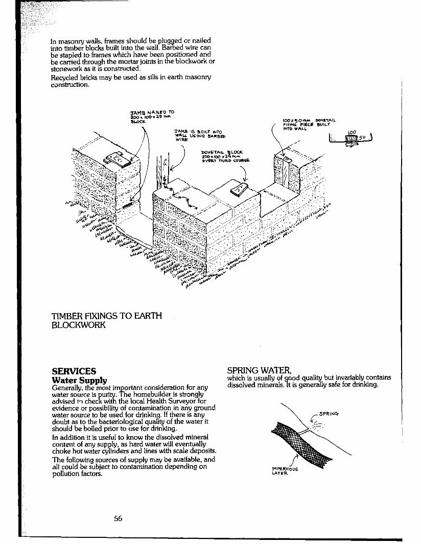
In masonry walls, frames should be plug ed or nailed into timber blocks built into the wall. Bar % ed wire can be stapled to frames which have been ositioned and
rl be carried through the mortar joints in t e blockwork or stonework as it is constructed. Recycled bricks may be used as sills in earth masonry construction.
100x50nm MwLTAlL FWNG PIPCL BUICr
TIMBER FIXINGS TO EARTH BLOCKWORK
SERVICES Water Supply Generally, the most important consideration for any water source is advised to chec K
urity. The homebuilder is strongly with the local Health Surveyor for
evidence or possibility of contamination in any ground water source to be used for drinking. If there is any doubt as to the bacteriological quality of the water it should be boiled prior to use for drinking. In addition it is useful to know the dissolved mineral content of any supply, as hard water will eventually choke hot water cylinders and lines with scale deposits. The following sources of supply may be available, and ail could be subject to contamination depending on pollution factors.
SPRING WATER, which is usually of ood quality but invariably contains dissolved minerals. 9 t is generally safe for drinking.
56
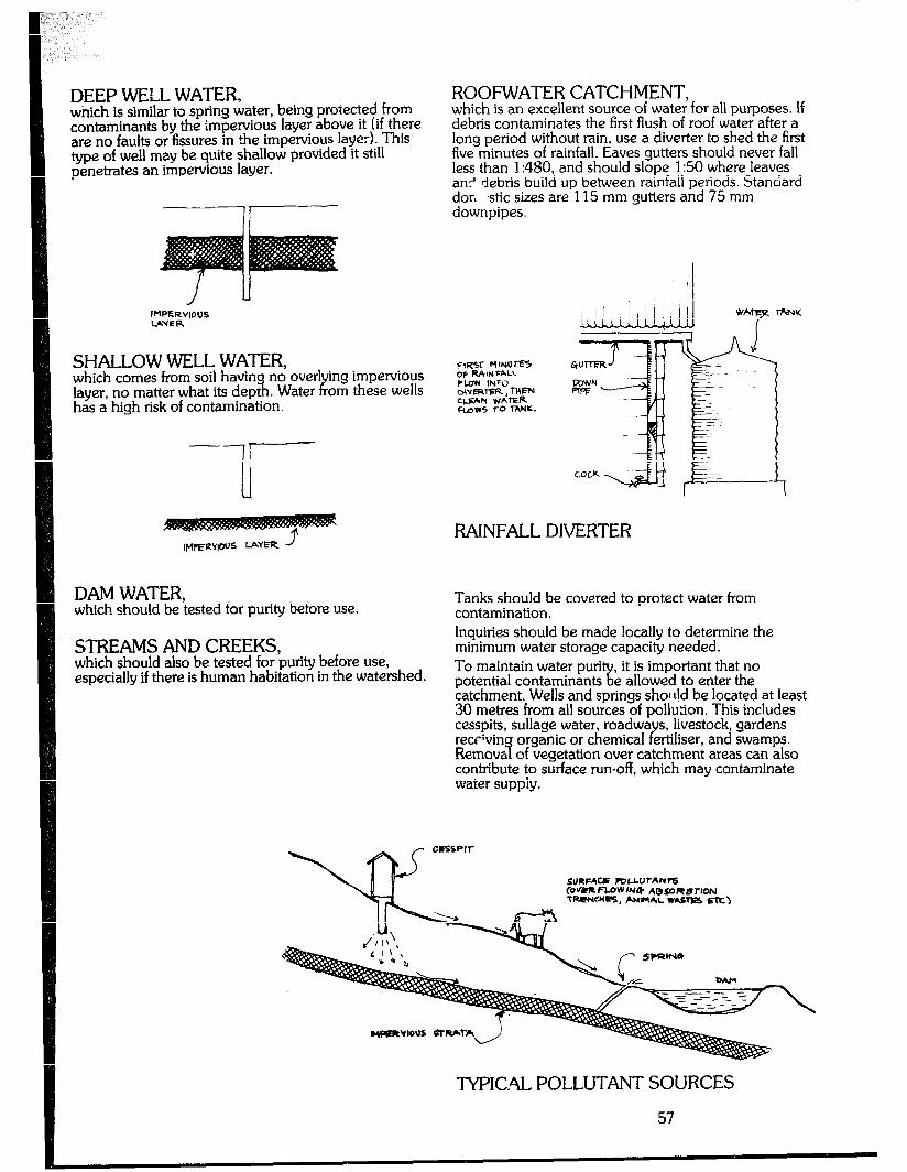
DEEP WELL WATER, wnich is similar to spring water, being protected from contaminants by the impervious layer above it (if there are no faults or fissures in the impervious layer). This type of well may be quite shallow provided it still penetrates an impervious layer.
, IMPERVIOUS IAVfR
SHALLOW WELL WATER, which comes from soil having no over1 layer, no matter what its depth. Water B
ing impervious om these wells
has a high risk of contamination.
IM~RWCUS LAYER
DAM WATER, which should be tested for purity before use.
STREAMS AND CREEKS, which should also be tested for purity before use, especially if there is human habitation in the watershed.
ROOFWATER CATCHMENT, which is an excellent source of water for all purposes. If debris contaminates the first flush of roof water after a long period without rain, use a diverter to shed the first five minutes of rainfall. Eaves gutters should never fall less than 1:480, and should slope 1:50 where leaves an? debris build up between rainfall periods. Standard dor, ,stic sizes are 115 mm gutters and 75 mm downpipes.
CIKV- rlINUrE5 OF RAIN FALL PLOW INTO DlVRlrFR , Tlllm CCEAN WATER FLOPS TO TANK.
RAINFALL DIVERTER
Tanks should be covered to protect water from contamination. Inquiries should be made locally to determine the minimum water storage capacity needed. To maintain water puri potential contaminants B
it is important that no k allowed to enter the
catchment. Wells and springs shor r!d be located at least 30 metres from all sources of pollution. This includes cesspits, sullage water, roadwa s, livestock, gardens reccrvin Remova of vegetation over catchment areas can also 7
organic or chemical ertiliser, and swamps. Y
contribute to surface run-off, which may contaminate water supply.
-M’ICAL POLLUTANT SOURCES
57
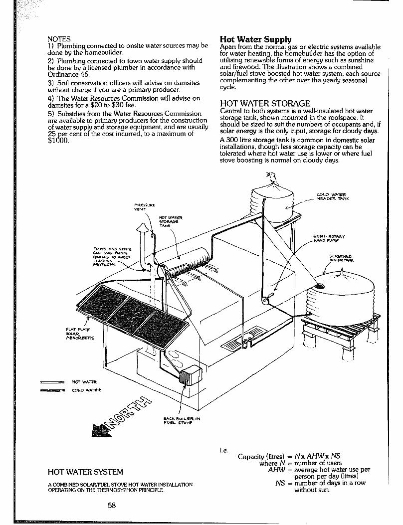
NOTES 1) Plumbing connected to onsite water sources may be done by the homebuilder. 2! Plumbing connected to town water supply should be done by a licensed plumber in accordance with Ordinance 46. 3) Soil conservation officers will advise on damsites without charge if you are a primary producer. 4) The Water Resources Commission will advise on damsites for a $20 to $30 fee. 5) Subsidies from the Water Resources Commission are available to primary producers for the construction of water suppl and storage equipment, and are usually g:gPgegrcent o Y the cost incurred, to a maximum of
PWZS5URE YEN r
Apart from the normal gas or electric systems available for water heating, the homebuilder has the option of utilising renewable forms of energy such as sunshine and firewood. The illustration shows a combined solar/fuel stove boosted hot water system, each source complementing the other over the yearly seasonai cycle.
HOT WATER STORAGE Central to both systems is a well-insulated hot water storage tank, shown mounted in the roofspace. It should be sized to suit thenumbers of occu ants and, if solar energy is the only input, storage for c oudy days. P A 300 litre storage tank is common in domestic solar installations, though less storage capacity can be tolerated where hot water use is lower or where fuel stove boosting is normal on cloudy days.
tDLD WATER - HEA3s. lw+w
i.e.
HQTWATERSYSTEM
Capacity (litres) = N x AHYIx fVS where fV = number of users
AHW = average hot water use per person per day (litres)
A COMBINED SOLARjFUEL STOVE HOT WATER INSTALIATION OPERATING ON THE THERMOSYPHON PRINCIPLE.
NS = number of days in a row without sun.
58
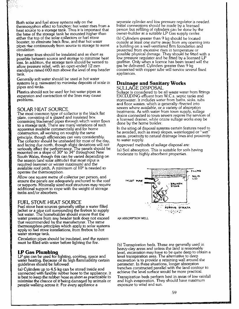
Both solar and fuel stove systems rely on the thennosyphon effect to function: hot water rises from a heat source to a storage tank. Thus it is important that the base of the storage tank be mounted higher than either the top of the solar collectors or fuel stove booster, to eliminate back flow, and that hot water pipes rise continuously from source to storage to assist circulation. Hot water lines should be insulated and as short as
P ossible between source and stora e to minimise heat
oss. In addition, the storage tank s it ould be vented to allow pressure relief, with an open-ended 12 mm standpipe raised 000 mm above the ievel of any header tank. General] soft water should be used in hot water systems e.g. rainwater) to minimise deposits of scale in Y pipes and tanks. Plastics should not be used for hot water pipes as expansion and contraction of the lines may cause problems.
SOLAR HEAT SOURCE The most common type of collector is the black flat plate, consistin of a glazed and insulated box containing blat ii ened pipes through which water flouts
to a storage tank. There are many variations of such apparatus available commercially and for home construction, all working on roughly the same rinciple, thou
f h efficiencies can vary considerably.
he collector s ?I ould be unshaded for most of the day, and facing due north, though slight deviations will not seriously affect the performance. The panels should be mounted on a slope of 30” to 34” throughout New South Wales, thou h this can be varied depending on the season (and so ar altitude) that most in 7 ut is reauired (summer or winter maximum) an B the available roof pitch. A minimum of 10” is needed to operate the thermosyphon. Allow one square metre of collector per person, and ensure the panels are adequate1 anchored to the roof or supports. Minimally sized roo Y structures may require additional support to cope with the weight of storage tanks and/or absorbers.
FUEL STOVE HEAT SOURCE Fuel stove heat sources generally utilise a water filled jacket or a pipe coil surrounding the frrebox to supply hot water. The homebuilder should ensure that the water pressure from any header tank does not exceed that recommended by the manufacturer. The same thermos appiy to T!ii
hon principles which apply to solar systems el stove installations, from firebox to hot
water storage tank. Circulation pipes should be insulated, and the system must be filled with water before lighting the fire.
umbing LP gaszn be used for li hting cooking space and water heating. Because o its h;gh flammability certain 9 guidelines should be followed: (a) Cyiinders up to 4.5 kg can be stored inside and connected with flexible rubber hose to the appliance. It is best to keep the rubber hose as short as racticable to minimise the chance of it being damaged 1 y animals or people walking across it. For every appliance a
separate cylinder and low ressure regulator is needed. Initial connections should E e made by a licensed person but refilling of cylinders can be done by the owner-builder at a suitable LP Gas supply centre. (b) Cylinders greater than 9 kg should be located outside at least one metre away from any opening into a building on a well-ventilated firm foundation and protected from excessive rises in temperature or
P ossible physical damage. The
ow pressure regulator and be ;i’ should be fitted with a
t-ted by a licensed LP gasfitter. Only when a licence has been issued will the gas be delivered. Cylinders greater than 9 kg connected with copper tube will service several fixed appliances.
Drainage and Sanitary Works SULLAGE DISPOSAL Sullage is considered to be all waste water from fittings EXCLUDING effluent from W.C.s, septic tanks and stormwater. It includes water from baths, sinks, tubs and floor wastes, which is generally directed into sewers where available, or a variety of absorption treatments. As with water from town supply, sullage drains connected to town sewers require the services of a licensed drainer, while onsite sullage works may be done by the home builder. In the sitin of disposal systems certain features need to be avoide 2 , such as steep slopes, waterlogged or “wet” areas proximity to natural drainage lines and proximity to water supply. Approved methods of sullage disposal are: (a) Soil absorption. This is suitable for soils having moderate to highly absorbent properties.
INLET PIPE
FILWG
SOLID LID
. .:’ POliOUs LtRATA .: . . .
. : ..; .-.:, ; ‘; F
AN ABSORPTION WELL
(b) Transpiration beds. These are generally used in heavy-clay areas and unless the land is reasonably level, excavation may have to be quite deep to obtain a level transpiration area. The alternative to deep excavation is to provide a retaining wall around the perimeter. In these situations, longer absorption trenches constructed parallel with the land contour to achieve the level surface would be more practical. Transpiration beds perform best in areas of low rainfall and high evaporation. They should have maximum exposure to wind and sun.
59
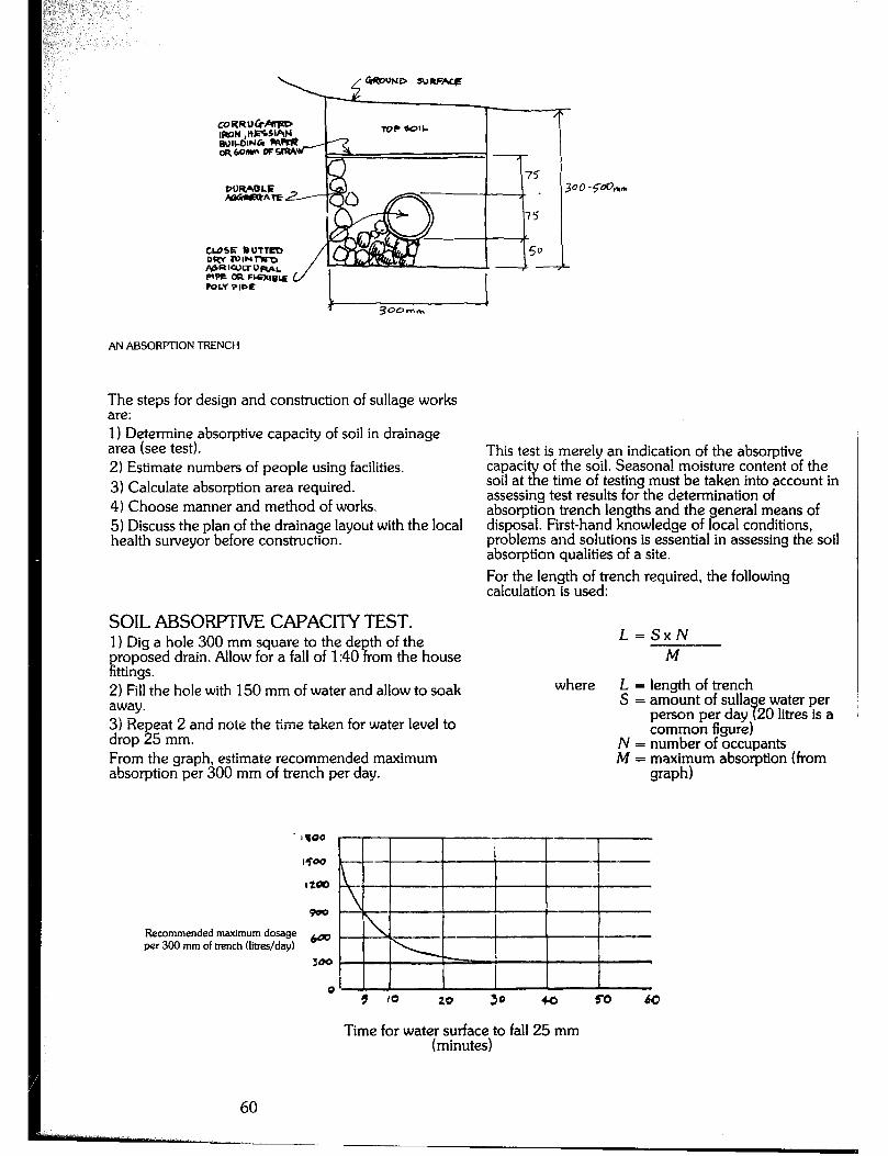
60
T 30omm
AN ABSORFTfON TRENCH
The steps for design and construction of sullage works are : 1) Determine absorptive capacity of soil in drainage area (see test). 2) Estimate numbers of people using facilities. 3) Calculate absorption area required. 4) Choose manner and method of works. 5) Discuss the plan of the drainage layout with the local health surveyor before construction.
SOIL AEiSOFWIlVE CAF’ACITY TEST. 1) Dig a hole 300 mm square to the depth of the
1 roposed drain. Allow for a fall of 1:40 from the house ttings.
2) Fill the hole with 150 mm of water and allow to soak away. 3) Repeat 2 and note the time taken for water level to drop 25 mm. From the graph, estimate recommended maximum absorption per 300 mm of trench per day.
This test is merely an indication of the absorptive capaci of the soil. Seasonal moisture content of the soil at x e time of testing must be taken into account in assessing test results for the determination of absorption trench lengths and the general means of disposal. First-hand knowledge of local conditions, problems and solutions is essential in assessing the soil absorption qualities of a site. For the length of trench required, the following calculation is used:
L=SxN M
where L = length of trench S = amount of sulla e water per
person per day 9 20 litres is a common figure)
N = number of occupants M = maximum absorption (from
graph)
Recommended maximum dosage 6oo per 300 mm of trench flit&day)
300
Time for water surface to fall 25 mm (minutes)
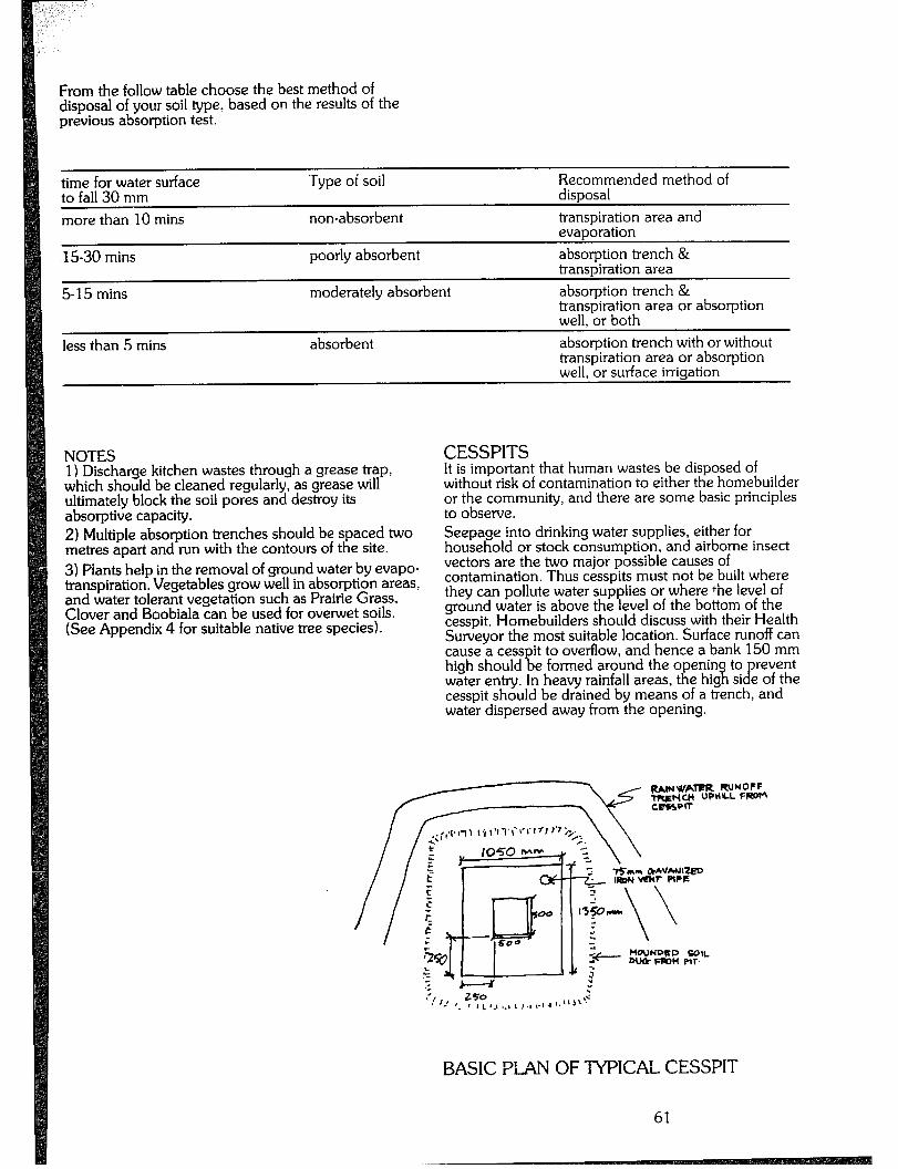
From the follow table choose the best method of disposal of your soil type. based on the results of the previous absorption test.
time for water surface to fall 30 mm more than 10 mins
15-30 mins
5-l 5 mins
less than 5 mins
Type of soil
non-absorbent
poorly absorbent
moderately absorbent
absorbent
Recommended method of disposal transpiration area and evaporation absorption trench & transpiration area absorption trench & transpiration area or absorption well, or both absorption trench with or without transpiration area or absorotion well, or surface irrigation ’
NOTES 1) Discharge kitchen wastes through a grease trap, which should be cleaned regularly, as grease will ultimately block the soil pores and destroy its absorptive capacity. 2) Multiple absorption trenches should be spaced two metres apart and run with the contours of the site. 3) Piants help in the removal of ground water by evapo- transpiration. Vegetables grow well in absorption areas, and water tolerant vegetation such as Prairie Grass, Clover and Boobiala can be used for over-wet soils. (See Appendix 4 for suitable native tree species).
CESSPITS It is important that human wastes be disposed of without risk of contamination to either the homebuilder or the community, and there are some basic principles to observe. Seepage into drinking water supplies, either for household or stock consumption, and airborne insect vectors are the two major possible causes of contamination. Thus cesspits must not be built where they can pollute water supplies or where the level of ground water is above the level of the bottom of the cesspit. Homebuilders should discuss with their Health Surveyor the most suitable location. Surface runoff can cause a cesspit to overflow, and hence a bank 150 mm high should be formed around the openin to revent water entry. In heavy rainfall areas, the hig w si e of the cesspit should be drained by means of a trench, and water dispersed away from the opening.
UAINWAIFR RUNOPF Tft~ft~~l UPHlLL FW
BASIC PLAN OF TYPICAL CESSPIT
61
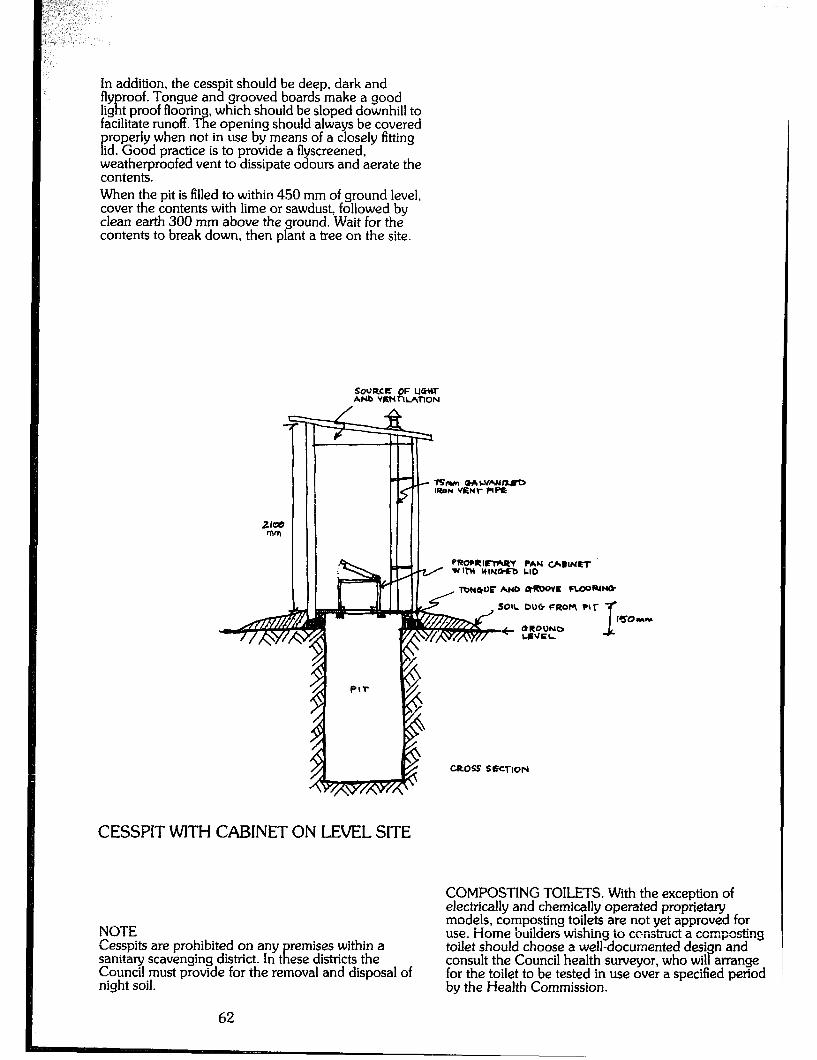
In addition, the cesspit should be deep, dark and fly roof. Tongue and grooved boards make a good 1igf;)t proof floorin facilitate runoff. T-i?
which should be sloped downhill to ‘e opening should always be covered
P roperly when not in use by means of a closely fitting
id. Good practice is to provide a flyscreened. weatherproofed vent to dissipate odours and aerate the contents. When the pit is filled to within 450 mm of ground level, cover the contents with lime or sawdust, followed by clean earth 300 mm above the ground. Wait for the contents to break down, then plant a tree on the site.
SO’JRCE OF WtU ANB VmnlAnON
PWUI~I+UY PAN WBINQT wlbl UINCkfO LID
l’O#Wr AND Lt-E -R(w
SOIL DW FROM ?{I-
CESSPIT WITH CABINET ON LEVEL SITE
NOTE Cesspits are prohibited on any remises within a sanitary scavenging district. In t ifi ese districts the Council must provide for the removal and disposal of night soil.
-0% SECTION
COMPOSTING TOILETS. With the exception of electrically and chemically operated proprietary models, composting toilets are not yet approved for use. ‘Home builders -wishing to construct a composting toilet should choose a well-documented desi consult the Council health surveyor, who wil P
n and arrange
for the toilet to be tested in use over a specified period by the Health Commission.
62
Electrical Work CONNECTION TO 240 VOLT AC PUBLIC SUPPLY Where a public supply is available and the homebuilder wishes to connect to it, wiring must be carried out by a licensed electrician accordin
8 to the Australian
Standard Wiring Rules (AS3 00 - Part 1).
POSSIBLE FUTURE CONNECTION TO PUBLIC SUPPLY Where a public sup
tE ly is available and connection to it
may be desired in e future then it is recommended that wirin
7 be installed in accordance with the AS
Wiring Ru es (AS 3000 - Part 1) for medium voltage AC supply.
EXTRA LOW VOLTAGE ELECTRICAL INSTALLATION Where a 240-volt mains supply is not available or not required, an extra low voltage (commonly 12-volt) supply can be installed by the home builder. While the IZvolt electrical system is relatively simple and safe to install, it is important that care is taken as faulty connections and fittings can cause poor performance and rapid deterioration of relatively expensive supply and storage components. The followin
P is an outline of the principles of extra low
voltage insta lation design: 1. ivfuximum current demand is estimated. This determines cable and fuse sizes. 2. Muximum energy demand is calculated (current per hour). This determines battery capacity required (in amp hours) and the appropriate charging system (solar cells, wind or water sources, internal combustion generator, etc.).
ESTIMATING DEMAND In most electrical installations, every appliance will not be working simultaneously, and hence the s
g stem
should be designed to meet the most proba le maximum demand rather than the potential total load. In a mains suppiied system it is necessa consider the load connected in terms of ‘x
only to e current that
will flow through the cables. However, in a battery system, time is a vital factor since the battery stores a certain amount of energy which can be dissipated by a low load over a long period as well as by a high load over a short period. The maximum current demand is the sum of the current drawn by each appliance likely to be operated simultaneously, and is expressed in amperes (amps). Alternative] be summe cy
, the individual wattages or voltamps can , and divided by the voltage (12) to give
amps. Some loads draw a higher current than their watt ratings indicate (e.g. fluorescent lamps and refrigerators) so it is preferable to use the current rating of the appliance rather than the watt rating. The maximum ene expected to be calle TV
demand is the energy that is upon from the battey system
between charges. It is calculated by adding the load (in amps) mdtipiied Dj; the operating time (in hours) of each ap liance that will be used during the discharge period. f-h is is the required capacity (in amp-hours) of the battery. A suitably sized charging system should be
matched with this demand to avoid flat batteries, and consequent cell damage.
INSTALLATION The plague of all electrical systems is that the cables through which the current flows are not perfect conductors, and have a low but significant resistance. (This same resistance produces heat in an electric radiator and light and heat in a filament lamp.) Cable resistance causes a loss in
P ower (given off as heat in
the cable) and a drop in vo ta is especially significant in a 1 8
e to the appliance, which -volt battery system.
Consider a 40-watt incandescent lamp. The current drawn on a 240~volt system is 40 divided by 240 = 0.17 amps with a cable loss of 0.03 wafts for a given length. The current drawn on a 12-volt system will be 40 divided by 12 = 3.3 amps, the cable losses being 11. I watts for the same length. These power losses may be minimised, but not eliminated, by the followed procedures: 1) Keep cables as short and direct as possible. Locate the battery at the geo installation, but in sue
raphical centre of the a a wa that the safety of the
battery storage is maintaine cy 2) Use conservative (i.e. larger) rated cables to keep temperatures low and hence voltage loss minimal. Ventilation around cables helps. 3) Observe good connection practice. Joints should be free of dirt and oxide coatings. Screwed connections should be tight and defective switches and sockets should be replaced. Once,the maximum demand for each circuit has been determined, suitable cable sizes should be selected. It is usually nore practical to use one cable size (e.g. 20- amp) and arrange the number of circuits so that the cable is not overloaded, and is preferabl
ti underloaded.
Althou h 12-volt automotive cable can be pre P
e used, it may erable to use 240~volt cable (say, 20 amp) as it
has superior mechanical protection and lends itself to more secure connection to switches and outlets which will probably be 240~volt equipment (i.e. normal switches, outlets and plugs).
PROTECTION AND SAFETY The electrical system must be protected from damage in a manner which minimises disruption if a fault occurs. Wiring should be located so as to avoid accidental damage, and should be secured so that it is supported by the structure without strain. Do not nail through concealed wiring! Cables should not be ‘oined between outlets, switches and so on, but should il e looped from outlet to outlet. This minimises joints, increases reliabili
3 and also allows damaged cable to be
replace if needed by using the old cable to draw a new one into position. Electrical protection is necessanj to prevent damage to the wiring in the event of, say, a short circuit. The same applies to the battery system. In order to minimise disruption, the protection should isolate only the fault area from the supply. This is achieved by using fuses to
P rotect cables, and by usin
il a number of circuits
cables) to sup ly the insta should be use if
ation. Two or more circuits , depending on the size of the
63
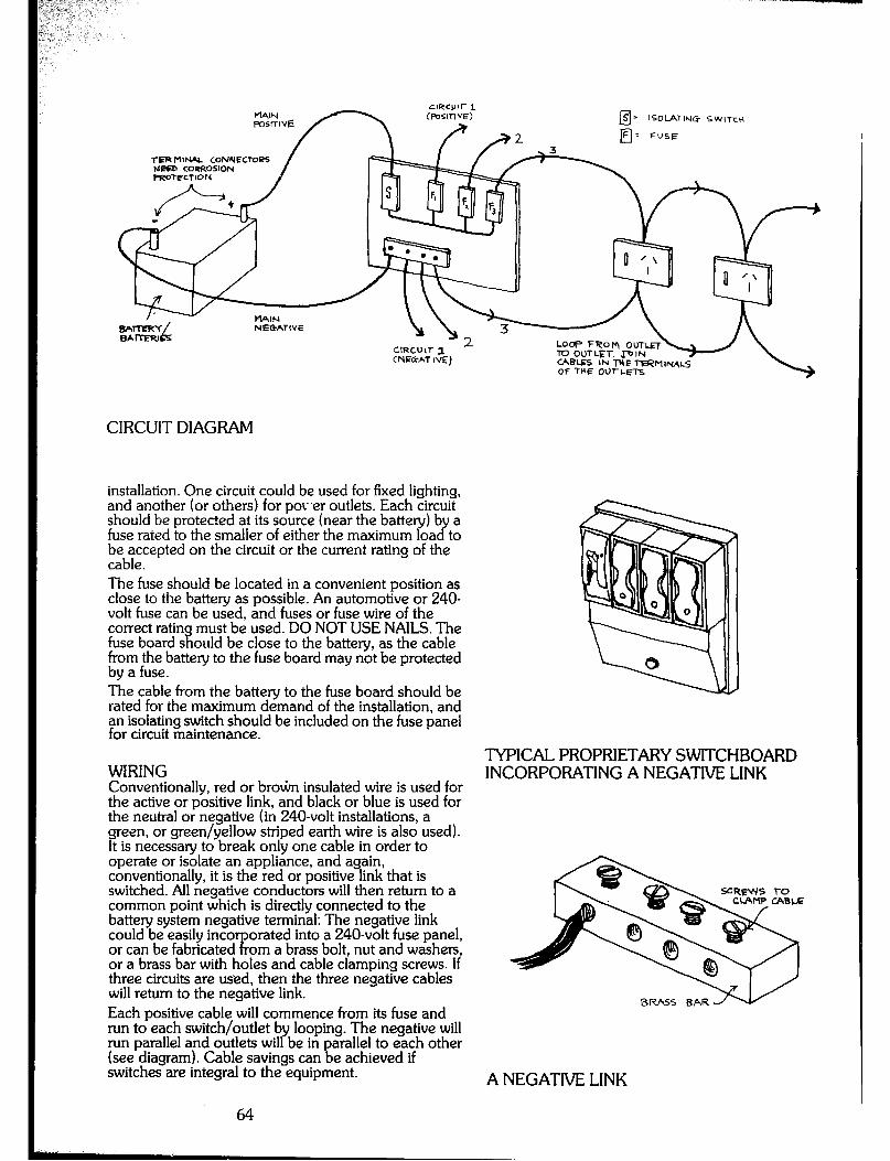
ISOLATIr.4G SWlTcH
TIERMINAL CONYECTOOPS NRD CoeFiOSIoN
(NIXi-Al ~4) l0 OUTLET. J-DIN
OF +UE OUl-Ml-S
CIRCUIT DIAGRAM
installation. One circuit could be used for fixed lighting, and another (or others) for pov.er outlets. Each circuit should be protected at its source (near the battery) b a fuse rated to the smaller of either the maximum loa 2 to FzbTcepted on the circuit or the current rating of the
The fuse should be located in a convenient position as close to the battery as possible. An automotive or 240- volt fuse can be used, and fuses or fuse wire of the correct ratin must be used. DO NOT USE NAILS. The fuse board s a ould be close to the battey, as the cable from the battery to the fuse board may not be protected by a fuse. The cable from the battery to the fuse board should be rated for the maximum demand of the installation, and an isolating switch should be included on the fuse panel for circuit maintenance.
WIRING Conventionally, red or br0G-r insulated wire is used for the active or positive link, and black or blue is used for the neutral or negative (in 240~volt installations, a green, or green/yellow striped earth wire is also used). It is necessary to break only one cable in order to operate or isolate an appliance, and again, conventionally, it is the red or positive link that is switched. All negative conductors will then return to a common point which is directly connected to the battery system negative terminal: The negative link could be easily into or can be fabricated ‘R
orated into a 240~volt fuse panel, om a brass bolt, nut and washers,
or a brass bar with holes and cable clamping screws. If three circuits are used, then the three negative cables will return to the negative link. Each positive cable will commence from its fuse and run to each switch/outlet by looping. The negative will run parallel and outlets will be in arallel to each other (see diagram). Cable savings can ! e achieved if switches are integral to the equipment.
TYPICAL PROPRIETARY SWITCHBOARD INCORPORATING A NEGATIVE LINK
A NEGATIVE LINK
64
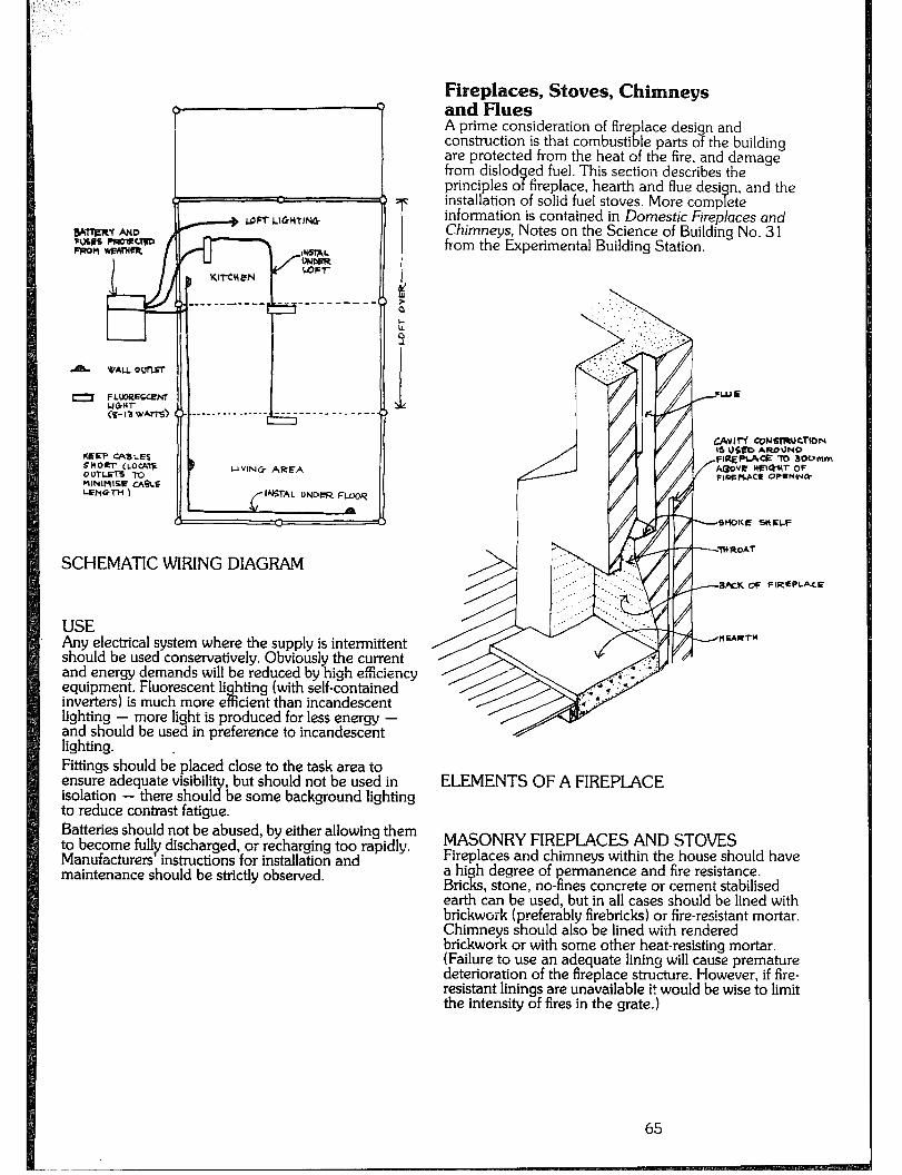
-
LOFT LIGHTI~
tE(EEP CQLES SHOm- (LOWTE OUTLInE To MINIMlEE UeLE WNG,-H 1
UVlNCr AREA
/I~Tf,L UNDCR FUQR
SCHEMATIC WIRING DIAGRAM
USE Any electrical system where the supply is intermittent should be used conservatively. Obviously the current and energy demands WI! be reduced by high eficiency equipment. Fluorescent Ii inverters) is much more e
hting (with self-contained iii cient than incandescent
lighting - more light is produced for less energy - and should be used in preference to incandescent lighting. . Fittings should be placed close to the task area to ensure adequate visibili
2 , but should not be used in
isolation - there shoul to reduce
be some background lighting contrast fatigue.
Batteries should not be abused, by either allowing them to become fully discharged, or recharging too rapidly. Manufacturers instructions for installation and maintenance should be strictly observed.
Fireplaces, Stoves, Chimneys and Flues A prime consideration of fire lace desi n and construction is that combusti & le parts o the building 7 are protected from the heat of the fire, and damage from dislod principles o 9
ed fuel. This section describes the fireplace, hearth and flue desi
installation of solid fuel stoves. More B n, and the
camp ete information is contained in Domestic Fireplaces and Chimneys, Notes on the Science of Building No. 31 from the Experimental Building Station.
CAvlVf C0NSlWCTlON IS US- AROUND FlREPlA= TO 3OOmm
fAC30VE tW3Q-W OF F,MpbACE OP=uIHlt
B&K OF FIREPLACE
ELEMENTS OF A FIREPLACE
MASONRY FIREPLACES AND STOVES Fireplaces and chimneys within the house should have a high degree of permanence and fire resistance. Bricks, stone, no-fines concrete or cement stabilised earth can be used, but in all cases should be lined with brickwork (preferably firebricks) or fire-resistant mortar. Chimneys should also be lined with rendered brickwork or with some other heat-resisting mortar. (Failure to use an adequate lining will cause premature deterioration of the fireplace structure. However, if fire- resistant linings are unavailable it would be wise to limit the intensity of fires in the grate.)
65
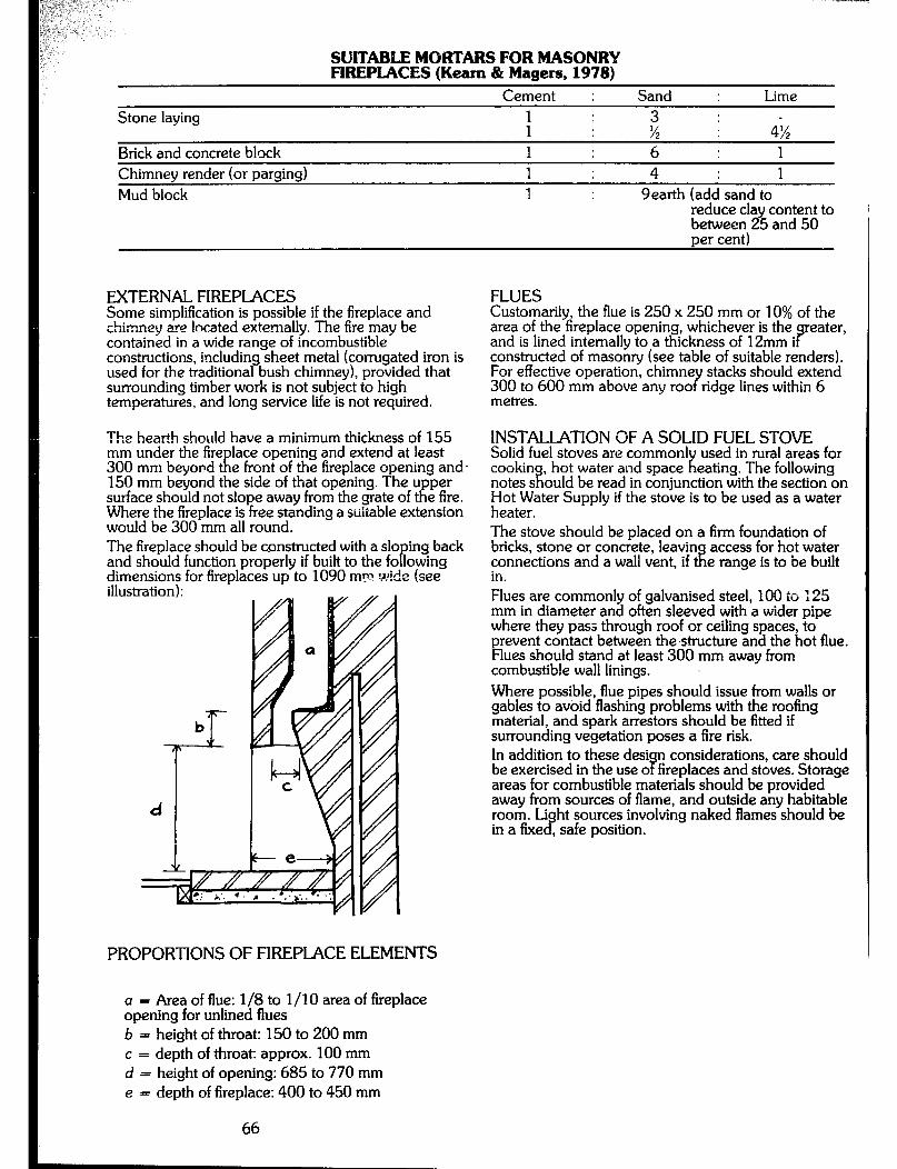
SUTAREE MORTARS FOR MASONRY FIREPLACES (Keam & Masers. 1978)
Cement : Sand : Lime Stone laying
Brick and concrete block ; I ; ; 4% 1 : 6 : 1
Chimney render (or parging) Mud block
1 : 4 : 1 1 : 9earth (add sand to
reduce clay content to i , between 25 and 50 per cent)
EXTERNAL FIREPLACES Some simplification is possible if the fireplace and chimney are located externally. The fire may be contained in a wide range of incombustible constructions, including sheet metal (corrugated iron is used for the traditional bush chimney), provided that surrounding timber work is not subject to high temperatures, and long service life is not required.
The hearth should have a minimum thickness of 155 mm under the fire lace opening and extend at least 300 mm beyond t R e front of the fireplace opening and. 150 mm beyond the side of that opening. The upper surface should not slope away from the grate of the fire. Where the fireplace is free standing a suitable extension would be 300 mm all round. The fireplace should be constructed with a slo ing back and should function properly if built to the fo P lowing dimensions for fireplaces UD to 1090 rnF ?ide (see
d
illustration): s *
PROPORTIONS OF FIREPLACE ELEMENTS
a = Area of flue: l/S to l/l 0 area of fireplace opening for unlined flues b = height of throat: 150 to 200 mm c = depth of throat: approx. 100 mm d = height of opening: 685 to 770 mm e = depth of fireplace: 400 to 450 mm
66
FLUES Customarily, the flue is 250 x 250 mm or 10% of the area of the fireplace opening, whichever is the eater, and is lined internally to a thickness of 12mm i B constructed of masonry (see table of suitable renders). For effective operation, chimne stacks should extend 300 to 600 mm above any roo Y ridge lines within 6 metres.
INSTALLATION OF A SOLID FUEL STOVE Solid fuel stoves are common1 cookin , hot water and space
i? ifl
used in rural areas for eating. The following
notes s ould be read in conjunction with the section on r;;c~ater Supply if the stove is to be used as a water
The stove should be placed on a firm foundation of bricks, stone or concrete, leavin connections and a wall vent, if t!
access for hot water e range is to be built
in. Flues are commonly of galvanised steel, 100 to 125 mm in diameter and often sleeved with a wider pipe where they pass through roof or ceiling spaces, to prevent contact between the structure and the hot flue. Flues should stand at least 300 mm away from combustible wall linings. Where possible, flue pipes should issue from walls or gables to avoid flashing problems with the roofing material, and spark arrestors should be fitted if surrounding vegetation poses a fire risk. In addition to these desi n considerations, care should be exercised in the use o 9 fireplaces and stoves. Storage areas for combustible materials should be provided away from sources of flame, and outside any habitable room. Li in a fixe c?
ht sources involving naked flames should be , safe position.

APPENDIX 1 Policy on Multiple The Department of
Occupant P nvironment and P anning’s
Circular 44 is intended to give guidance to Council when formulating their policies on Multiple Occupancy of Farms. To: All Councils outside Sydne Mountains, Camden,
Region and Blue Campbei town, Coio, Gosford, Y
Woilondiily and Wyong Councils. CIRCUIAR NO. 44
Dear Sir, POLICY - MULTIPLE OCCUPANCY ON FARMS On 7th November, 1979, Circular No. 35 (Interim Policy - Multiple Occupancy on Farms) was circulated to the above listed Councils. Since that time there has been considerable response to the Interim Policy from Councils and the Local Government and Shires Associations Committee on Local Government Regulations and Alternative Lifestyle Developments. 2. Full background details to the multiple occupancy issue and reasons for ado included in Circular No. 4)
tion of the Interim Policy are 5.
3. On the basis of response to the Interim Policy a formal Poiic for Multiple Occupant
x Y on Farms,
together wi a standard enabling C ause, has been prepared and is presented in this Circular. 4. Listed below are the policy statements on which the standard enablin now adopted as 8
Clause was based and which are ianning and Environment
Commission policy for multi case the poli
ie occupancy. In each
subclause an 7 statement is ollowed by a suggested P
/or explanatory notes. POLICY ONE THE-NEW S&JTI-I WALES PLANNING AND ENVIRONMENT COMMISSION SUPPORTS THE MULTIPLE OCCUPANCY, ON A CLUSTERED OR DISPERSED BASIS, OF RURAL PROPERTIES IN COMMON OWNERSHIP AS AN APPROPRIATE IAND USE FOR RURAL AREAS SUBJECT TO A NUMBER OF ENVIRONMENTAL AND LOCATIONAL GUIDELINES.
1. STANDARD I-D-0. SUBCLAUSE: Notwithstanding Clause . . . (forty hectares policy) development for residential purposes comprising
& ermanent dwelling or living accommodation may e carried out on land to which this clause a
with the consent of Council subject to P plies
camp iance with conditions listed in the following subclauses.
POLICYTWO: A COUNCIL MAY ADOPT, AS IS LOCALLY APPROPRIATE. ONE OF THE FOLLOWING ALTERNATIVES FOR THAT AREA WITHIN WHICH MULTIPLE OCCUPANCY ON FARMS CAN BE APPROVED. A. AREA ZONED RURAL 1 (Al; yiAyEo”IRIED PORTION OF AREA ZONED RURAL
C. AREA ZONED RURAL (SMALL HOLDING) 1 (C). 2. STANDARD I.D.O. SUBCLAUSE ALTERNATIVE B: This clause a of land in the Parishes of A, B, t?
plies to those parts
situated: , D and E as are
al within the Shire of Farmland; and b) within land zoned Rural 1 (a).
Note: Application for multiple occupant designated area should be made throng f:
within the the Council’s
normal development application process. POLICY THREE: HOLDINGS Td WHICH MULTIPLE OCCUPANCY STATUS IS GRANTED SHOULD GENERALLY HAVE A MINIMUM AREA OF FORTY HECTARES WITH AN ABSOLUTE MINIMUM OF TWENTY HECTARES WHERE SUCH IS THE [F;RE;I,G SUBDMSION LOT SIZE IN THE
3. STANDARD I.D.O. SUBCLAUSE: The land upon which the development is carried out has an area of not less than the minimum for subdivision prescribed by clause . . . (e.g. Forty Hectares).
POLICY FOUR: FUTURE SUBDMSION OF ANY HOLDING GRANTED MULTIPLE OCCUPANCY STATUS IS PROHIBITED AS LONG AS IT RETAINS THAT STATUS.
4. STANDARD I.D.O. SUBCLAUSE: Whenever land is developed in accordance with this clause it is and remains unsubdivided either under the Local Government Act, 19 19, or the Strata Title Act, 1973, so as to comprise a single parcel.
POLICY FIVE: ANY APPLICANT FOR MULTIPLE OCCUPANCY STATUS ON A HOLDING MADE UP OF MORE THAN ONE PARCEL, PORTION OR PART PORTION SHALL AT THE TIME OF APPL’CATION gTyTJKE APPLICATION FOR CONSOLIDATION
5. STANDARD I.D.O. SUBCLAUSE: Nothing in subclause 4 shall prevent the Council from determining an ap iication for consent under this clause in respect o P land in more than one parcel but any consent granted hereunder shall be subject to the requirement that the land be consolidated into a single parcel prior to the development being carried out.
POLICY SIX: ANY HOLDING SUBJECT TO AN APPLICATION FOR MULTIPLE OCCUPANCY STATUS MUST BE OWNED IN ITS ENTIRETY IN COMMON BY AT LEAST TWO-THIRDS OF ALL ADULTS RESIDING ON THE LAND, OR MUST BE ;;;E’!‘N.SE OWNED ON BEHALF OF THOSE
6. STANDARD I.D.O. SUBCLAUSE: The land upon which the development is carried out is owned in its entirety in common by at least two-thirds of ail adults residing on the land or is otherwise owned on behalf of those persons.
Note: “Otherwise owned on behalf of” means equal ownershi members F:
through a trust-in-common, trust ip, co-operative shareholding, company
shareholding, etc. POLICY SEVEN: APPROVAL FOR MULTIPLE OCCUPANCY STATUS SHALL ONLY BE GRANTED TO THOSE COMMUNITIES ON WHICH EXISTING OR PROPOSED BUILDING DENSITIES DO NOT EXCEED THAT REASONABLY REQUIRED TO HOUSE ONE PERSON FOR EACH HECTARE OF THE HOLDING IN QUESTION.
7. STANDARD I.D.O. SUBCLAUSE: The residential accommodation shall not exceed that reasonabi required to house one person for each hectare o Y the land.
67

Note: Person reiers to both adults and children,
P ermanent residents and temporary guests (short &
ong term). POLICY EIGHT: IN CONSIDERING AN APPLICATION FOR MULTIPLE OCCUPANCY, THE COI INCIL SHOULD TAKE ACCOUNT OF _--_--- -~ ENVIRONMENTAL AND LOCATIONAL MATTERS, INCLUDING: 1 ADEQUACY OF ACCESS
/$$QU,QUAC& OF WATER SUPPLY AND
l ADEQUACY OF WASTE DISPOSAL FAClLITIES l ;:3TIONSHIP TO NEIGHBOURIl’lG LAND
l 13E3mTI-I;SHIP TO EXISTING FACILITIES &
l BUSH FIRE RISK l POTENTIAL EROSION HAZARD l SITE VEGETATION COVERAGE l AGRICULTURAL SUITABILITY l SITING OF PROPOSED BUILDINGS.
8. STANDARD i.D.0. SUBCLAUSE: In considering an application under this clause the Council shall have particular regard to the environmental and locational suitability of the land for the proposed development.
Note: No specific standards on these matters are defined because in each local government area conditions will vay. Councils can choose either to s ecify standards and include them in an enabling c ause, or evaluate each application on its merits and P recommend changes to site and development plans where appropriate. POLICY NINE: HOLDINGS GRANTED MULTIPLE OCCUPANCY STATUS SHOULD BE USED ONLY FOR PERMANENT RESIDENTIAL PURPOSES AND SHOULD NOT BE USED FOR HOTEL. MOTEL. C-ARAVAN PARK OR ANY OTHER TYPE OF HOLIDAY, TOURIST OR WEEKEND RESIDENTIAL ACCOMMODATION.
9. STANDARD I.D.O. SUBCLAUSE. Whenever land is developed in accordance with this clause, any development for -the purpose of a hotel, motel, caravan
cr ark, or an
weeken residerrria Y other type of holiday, tourist or accommodation is prohibited.
Note: This policy should not be used to prohibit tern oray accommodation associated with teaching or
is wor hop activities proposed for bona fide new settler communities. This clause is designed to
P revent
exploitation of the policy for commercia associated with the alternative lifestyles o P
m-poses not new settlers.
POLICY TEN: MULTIPLE OCCUPANCY HOLDINGS IN EXISTENCE PRIOR TO GAZETTAL OF AN ENABLING CLAUSE THAT WERE DEVELOPED WITHOUT COUNCIL APPROVAL, SHOULD BE LEGALISED UNDER THE ENABLING CLAUSE IF THEY MEET THE REQUIREMENTS OF THE CLAUSE.
10. STANDARD l.D.0. SUBCLAUSES: (Al Permission is hereby granted in respect of each of the parcels of land described in Schedule . . . (of the gazettai notice) for the following development:
a) development of the land for residential
P m-poses comprising permanent dwelling or
iving accommodation; and
b) the use of the buildings in existence on the aforesaid land at the date upon which this clause takes effect for the purposes referred to in paragraph (a).
(B) Permission granted by subclause (A) in respect of any development referred to in subclause (Al shall:
a) operate in relation to the erection of any buildings, so as to permit only the erection of those buildings in existence on the aforesaid land, at the date upon which this clause takes effect; and b) in addition to its taking effect in accordance with subclause (Al and without prejudice to that subclause, be deemed to have been ranted by this order as in force immediately be ore the day 9 upon which that development was commenced on that day.
Note: Subclause (B)a limits approval to those buildings complete, or substantially complete, at the day of gazettai. Subclause (Bib retroactively iegaiises the action of building and the use of buildings completed prior to the gazettal date.
(C) Nothing in this subclause shall prevent the application of subclauses 1 to 9 (mentioned in this Circular Letter) in respect of an land the subject of this clause. but in any such app ication the Y development permitted by this clause shall be taken into account for the purposes of subclause 7.
POLICY ELEVEN: RESIDENTS OF EXISTING BUILDINGS ON MULTIPLE OCCUPANCY HOLDINGS WHICH HAVE BEEN LEGALISED UNDER THE ENABLING CLAUSE MUST SUBMIT BUILDING APPLICATION TO THE COUNCIL. THE COUNCIL SHOULD ALLOW AT LEAST ONE YEAR SUBSEQUENT TO GAZETTAL FOR EXISTING BUILDINGS TO CONFORM WITH REQUIREMENTS. POLICY TWELVE: ALL BUILDING PROPOSED FOR MULTIPLE OCCUPANCY HOLDINGS APPROVED SUBSEQUENT TO, OR AT THE TIME OF, GAZEITAL OF THE ENABLING CLAUSE MUST BE SUBJECT TO THE BUILDING APPLICATION PROCESS AND CONFORM WITH BUILDING REQUIREMENTS. Note: A Technical Advisory Group (Department of Architecture, Sydney University) has been retained by the N.S.W. Planning and Environment Commission to carry out the Experimental Building Area Programme and produce a series of adviso
7 documents on low
cost alternative building techno ogies and materials. The work is being assessed by representatives of the Department of Local Government, the Health Commission of N.S.W., the Lismore City Council, the Local Government Association, the Australian Institute of Health Surveyors, the Builders Licensing Board and the Building Surve ors Institute. The final report of the
oup is due after uiy, 1980 and will be circulated 9:
Y t ereafter. Note: The findings of the Technical Advisory Group are aimed, not at changing existing building regulations, but at assisting in their flexible administration and increasing the acce tabiiity of non-traditional low cost housing by Counci P Health and Building Inspectors. POLICY THIRTEEN: ALL APPLlCANTS FOR MULIPLE OCCUPANCY STATUS MUST PRESENT
68

WITH THEIR DEVELOPMENT APPLICATION A SITE AND DEVELOPMENT PLAN OF EXISTING AND PROPOSED CONDITIONS ON THE HOLDING IN QUESTION. Note: Development application fees have been raised as an issue of concern to both New Settlers and Council Ofllcers. It is open to the Council to determine under section 167 of the Local Government Act the appropriate level of development application fees for multi ie occupancy holdings. Provisions relating to deve opment application fees are also included in the P Environmental Planning and Assessment Act.
FURTHER INFORMATION 11. Should you require further advice on the policy please contact the Regional Manager concerned: Ncrthem, Mr. Rod Nichols, Grafton (066) 42 0622. Hunter, Mr. Ken Short, Newcastle (049) 2 3818. (2&$;i(Wyong, Mr. David Kettle, Gosford (0431
Iiiawarra, Mr. Percy Wyies, Woiiongong (042) 28 4644. !!&ttlast. Mr. Ted Schuitheis, Queanbeyan, (0621
Western, Mr. Adrian Boss, Sydney (02) 266 7111. POLICY FOURTEEN: THE ISSUE OF RATING MULTIPLE OCCUPANCY HOLDINGS IS A LOCAL MATTER AND SHOULD BE DEALT WITH AT THE
S dney Outer Western, Mr. Geoff Goodwin, Sydney &2)2667111.
LOCAL LEVEL. Note: The provisions of section 118 of the Local Government Act already confer a wide discretion upon councils in the determination of their ratin rural lands. With the flexibility possible un %
policies for er that
section in respect of the general rate and the various forms of differential general rates, most councils should find it possible to accommodate their policies.
!S;~tllr2~;. Charles Hill, Sydney (021
Yours faithfully.
R.L. PINCINI SECRETARY 3rd July, 1980
IMPLEMENTATION 5. The policy requirements are designed to ensure that only bona fide multiple occupancy holdings are approved. 6. It is proposed that the policy be implemented by way of an enabling clause in planning instruments. Preparation and gazettal of an enabling clause would be carried out by the Piannin and Environment Commission at the request o 9 the Council concerned. 7. The enabling clause procedure has been selected because of the dispersed nature of multiple occupancy cases, both in a Statewide and local government context, and its general ease of administration. The enabling clause will, however, empower Councils to exercise sufficient control over applications. 8. Councils will be able to take into account specific local conditions, particularly environmental and locational matters, and request that these conditions be considered by the N.S.W. Planning and Environment Commission in the preparation of a locally appropriate enabling clause. 9. If implementation is to take place under the Environmental Planning and Assessment Act, 1979, it could be effected either by a Council taking action to amend its planning instrument by way of the local
E lanning process, or by the Department of nvironment and P!anning taking similar action under
the State planning policy process.
MONITORING OF THE POLICY 10. In order to assess the workings of the the next few years, the Commission woul cr
olicy over
receiving brief details of all multiple occu appreciate
applications, whether ap roved or not. ancy
TR ese should be sent to the regional o Iii ces of the Planning and Environment Commission.
69

APPENDIX 2 Penalties The Act and the Ordinance provide for the following penalties: 1) A penalty of not more than $10 a day for occupation of “a building which has not been completed in accordance with the a proved plans and specifications” every B ay during which the occupation continues after notice from the Council. 2) A penalty of not more than $100 for the erection of a building in contravention of the Ordinance, and a daily penal of not more than $10 for any continuation of the o 2 ence. 3) Ten dollars for a first offence, $20 for a second offence and a daily penalty of not more than $1 a day after being found guilty of an offence under the Ordinance where a penalty is not elsewhere prescribed. 4) The same penalty as in (1) above for erecting a tent in contravention of the Ordinance or for failing to comply with any conditions attached to the approval for erecting a tent.

APPENDIX 3 1 Guide Letters to Council
LETTER TO COUNCIL, SEEKING MOVABLE DWELLING LICENCE
The Shire/Town Clerk Shire/Manicipality of . . . (Address)
(ADDRESS)
Date :
Dear Shire/Town Clerk,
I wish to apply for a "movable dwelling licence" to occupy my land at (describe location) from (date).
I intend to (describe intention and reasons, e.g. to erect a tent and live on the property to evaluate site and environmental conditions prior to submitting a building application for a permanent dwelling . ..).
I undertake to dispose of household waste and nightsoil and to comply with other Council requirements.
Yours faithfullv.
(NAME)
LETTER TO COUNCIL, SEEKING APPROVAL FOR OCCUPATION BEFORE COMPLETION
(ADDRESS)
The Shire/Town Clerk Shire/Municipality of . . . (Address)
Date:
Dear Shire/Town Clerk,
Re: New house at (location)
Following approval of my Building Application dated . . . . . . . . . your reference . . . . . . (if any), I now advise that the building has reached a habitable stage and I wish to occupy it prior to practical completion because . . . . . . (state reasons, e.g. nowhere else to live).
In my opinion the building is safe, healthy and weatherproof.
Yours faithfully,
71

UNUSUAL
(ADDRESS)
The Shire/Town Clerk, Shire/Municipality of . . . (Address)
Date:
Dear Shire/Town Clerk,
Re: Building Application Lot . . . . (location description)
In support of my building application dated . . . . . . . . . I submit the following statement and request for your further consideration.
I seek to erect a (complex, innovative, unusual, etc.) dwelling which is illustrated on the accompanying plans.
There is ample precedent for this structure and I enclose articles/photographs/other evidence for your further information.
Due to the complex nature of the structure, I am unable to supply structural analysis and calculations. Instead, I propose that the structural adequacy of the building be demonstrated on site after completion and before occupation. I believe.that the complete structure with dead loads imposed, demonstrated live loading where applicable, and simulated wind loading should be adequate proof of structural safety. (I attach details of loading simulations.)* Under these circumstances, I undertake full responsibility for any failure of the structure and for the costs of any tests.
I understand that Council may grant conditional approval for such structures under Part 43.1(l) of Ordinance 70 and now seek conditional approval for this application.
Yours faithfully,
(NAME)
* If available.
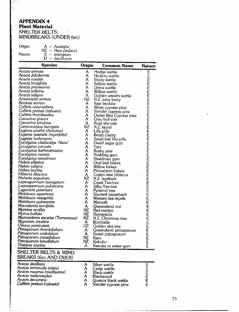
W'iNDBRiiS(Ui‘lDER6m)
Origin: A - Australia NZ - New Zealand
Acacia urn-rata Acacia falcifotmis Acacia nowitti Acacia longifolia Acacia provissima Acacia salicina Acacia saligna Arisotctelia sen-ata Banksia set-rata Caliims columellaris Call&is preissii (robusta) Call&is rhomboidea Casuarina glauca Casuarina torulosa Co ynocarpus laevigata Eugenia smithii (Acmeno) Eugenia australis (myrtifolia) Eugenia luehmanni Eucalyptus cladocalyx ‘Nana’ Eucalyptus cornuta Eucalyptus luehmanniana Eucalyptus nutans Eucalyptus steedmani Hakea elliptica Hakea saligna Hakea laurina Hibiscus filiaceus Hoheria populnea Leptos,oenu.m laevigatum Leptospennum pubescens Lagunaria patersoni Melaleuca squarrosa Melaleuca nesophila Melaleuca pubescens Macadamia temifolia Myrisine orvillei Myrtus bullata Metmsideros excelsa (Tomentosa) Myporum insulare OIeaii’a panicuiata Pittosporum rhombifolium Pittosporum undulatum Pittosporum crassifolium Pittosporum tenuifolium Tnstania launna
Hedge wattle Hickory wattle Sticky wattle Sallow wattle Orens wattle Willow wattle Golden wreath wattle N.Z. wine berry Saw banksia White cypress pine Slender cypress pine Oyster Bay Cypress pine Grey bull-oak Rose she-oak N.Z. laurel Lilly-pilly Brush the Small leaf li ly-pilly “y Dwarf sugar gum Yate Bush yate Nod J ing gum Steedman gum Oval ieaf hakea Willow hakea Pincushion hakea Cotton tree hibiscus N.Z. lacebark Coast Tea-tree Silky Tea-tree Pyramid tree Scented paperback zk;h tea myrtle
Queensland nut Red matipo Ramarama N.Z. Christmas tree Boobialla Golden ake-ake Queensland pittosporum ggt pittosporum
Eohuhu Kanuka or water gum
Acacia dealbata Acacia terminaiis (elata) Acacia meamsi (mollissima) Acacia melanoxylon Acacia decurrens Call&is preissii (robusta)
A Silver wattle A Cedar wattle A Black wattle A Blackwood A Queena black wattle A Slender cypress pine
73
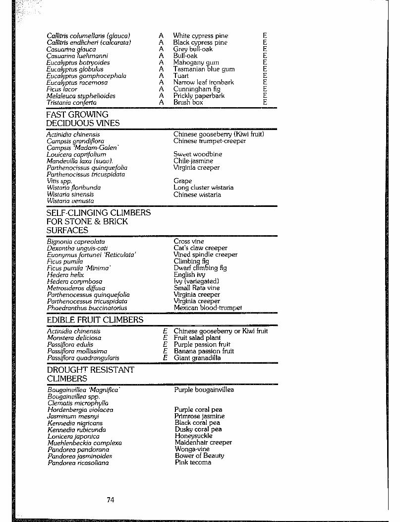
Callitis columellans ( laucal Call&is endlichen (ca carata) 7 Casunrina glauca Casuarina luehmanni Eucalyptus botyoides Eucalyptus globulus Eucalyptus gomphocephala Eucalyptus racemosa Ficus lacer Melaleuca styphelioides Tristania conferta
White cypress pine Black cypress pine Grey bull-oak Bull-oak Mahogany urn
% T;;;anian lue gum
Narrow leaf ironbark Cunningham fig ~-i,c~~b~xperbark
FAST GROWING DECIDUOUS VINES Actinidia chinensis Campsis grandiflora Campsis ‘Madam-Galen’ Louicera caprifolium Mandevilla laxa (suav). Parthenocissus quinquefolia Parthenocissus tricuspidata Vitis spp. Wistaria jloribunda Wistaria sinensis Wistaria venusta
Chinese gooseberry (Kiwi fruit) Chinese trumpet-creeper
Sweet woodbine Chile-jasmine Virginia creeper
Grape Long cluster wistaria Chinese wistaria
SELF-CLINGING CLIMBERS FOR STONE & BRICK SURFACES Bignonia capreolata Dexantha unguis-cati Euonymus fortunei ‘Reticulata Ficus pumila Ficus pumila ‘Minima ’ Hedera helix Hedera co ymbosa Metrosideros diffusa Parthenocessus quinquefolia Parthenocessus tricuspidata Phaedranthus buccinatonus
Cross vine Cat’s claw creeper Vined spindle creeper Climbing fig Dwarf climbing fig English ivy Ivy (variegated) Small Rata vine Virginia creeper Virginia creeper Mexican blood-trumpet
EDIBLE FRUIT CLIMBERS Actinidia chinensis Monstera deliciosa Passijlora edulis Passifiora mollissima Passifiora quadrangular-is
DROUGHT RESISTANT CLIMBERS
E Chinese gooseberry or Kiwi fruit E Fruit salad plant E Purple passion fruit E Banana passion fruit E Giant granadilla
Bougainvi!!ea ‘Magnifica’ Purple bougainvillea Bougainvillea spp. Clematis microphylla Hordenbergia violacea Jasminum mesnyi Kennedia nigricans Kennedia rubicunda Lonicera japonica Muehlenbeckia complexa Pandorea pandorana Pandorea jasminoides Pandorea ricasoliana
Purple coral pea Primrose jasmine Black coral pea Dusky coral pea Honeysuckle Maidenhair creeper Wonga-vine Bower of Beauty Pink tecoma
74

TREES FOR OVER-WET SITES - NATIVE SPECIES Acacia decurrens Acacia jloribunda Acacia longijolia Angophora costata Angophora inter-media Callicoma serratifolia Callistemon paludosus Callistemon pinifolius Callistemon rugulosus Callistemon salignus Callistemon viminalis Castanospermum australe Casuarina cunainghamiana Casuarina glauca Eucalyptus botyoides Eucalyptus camaldulensis Eucalyptus deanei Eucalyptus globulus Eucalyptus grandis Eucalyptus oreades Eucalyptus robusta Eucalyptus saligna Hymenosporum flavum Melaleuca quinquenervia Melaleuca styphelioides Melia azedarach Tristania iaurina
Black cvattle White sallow wattle Sydney olden wattle Smooth- % arked ap le Rou Blat wattle 9(
h-barked app e (fast growing) P
Swamp bottle brush Green-flowering bottle brush
White bottle brush Drooping bottle brush Black bean River she-oak Swam oak Banga ay or southern mahogany P River red gum Round-leaved gum Tasmanian blue gum Flooded gum Blue Mountains ash Swamp mahogany Sydney blue gum Native frangi anni Broad-leave paperbark B Frickly-leaved paperbark White cedar Water ctum
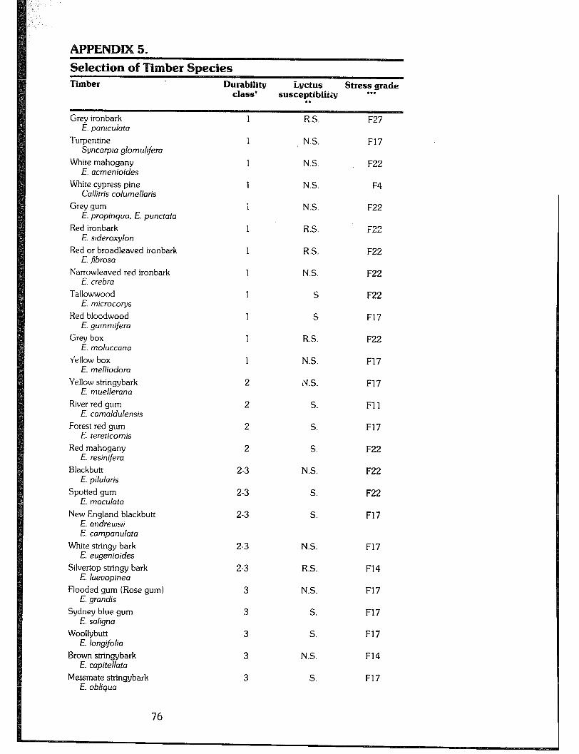
Selection of imber Species Timber Durability Lyctus Stress grade
class’ susceptibilkiy l ** . .
Grey ironbark E. panicuiata
Turpentine Syncarpia glomulifera
White mahogany E. acmenioides
White cypress pine Callitris columellaris
Grey gum E. propinqua. E. punctata
Red ironbark E. sideroxylon
Red or broadleaved ironbark E. .fibrosa
Narrowleaved red ironbark i. crebra
Tallowwood E. microcorys
Red bloodwood E. gummifera
Grey box E. moluccana
r’ellow box E. melliodora
Yellow stringybark E. muellerana
River red gum E. camaldulensis
Forest red gum E. tereticomts
Red mahogany E. resinifera
Blackbutt E. pilulatis
Spotted gum E. maculata
New England blackbutt E. andrewsii E. campanulata
White stringv bark E. eugenjoides
Silvertop stringy bark E. laevopinea
Flooded gum (Rose gum) E. grandis
Sydney blue gum E. sahgna
Woollybutt E. longifolia
Brown stringybark E. capitellata
Messmate stringybark F nMin,.n L. ““1’yL.v
76
1
1
1
1
1
1
1
1
1
1
1
1
2
2
2
2
2-3
2-3
2-3
2-3
2-3
3
3
3
3
3
R.S.
N.S.
N.S.
N.S.
N.S.
R.S.
R.S.
N.S.
s
S
R.S.
N.S.
1V.S.
S.
S.
S.
N.S.
S.
S.
N.S.
R.S.
N.S.
S.
S.
N.S.
S.
F27
F17
F22
F4
F22
F22
F22
F22
F22
F17
F22
F17
F17
Fll
F17
F22
F22
F22
F17
F17
F14
F17
F17
F17
F14
F17
Brushbox Tristania conferta
Silvertop ash E. siebeti
Brown barrel E. fastigata
Radiata pine Pinus mdiata
Oregon (Douglas fir) Pseudotsuga menziesii
33
4
4
4
t
R.
S.
S.
N.S.
N.S. N.S.
F17
F17
F14
F5 (seasoned)
FE
*Durability Class means resistance of the heartwood to attack by fungi and insects -
Class 1 gives 25-50 years service in the ground Class 2 gives 15-25 years service in the ground Class 3 gives 8-15 years service in the ground Ciass 4 should not be used in the ground.
l *Lyctus Susceptibility
E‘ - not susceptible
‘s: 1 rarely susceptible susceptible
***The Standards Association of Australia grades timber according to the stresses which it is able to sustain. These range from F3 3”
dings are given as ‘F’ values and (the strongest) to F4.
TERMITE RESISTANCE This means the ability of the heartwood to resist termite attack. Generally, the class 1 durability timbers i.e. the denser eucalypt timbers, turpentine, and white cypress pine show considerable resistance to termite attack, unlike most of the iightwei ht, light-coloured hardwoods which do not. fh is resistance may vary according to locality and so local experience will be invaluable in determining suitable species. Homebuilders should take care in the identification of timber species. Local knowledge may be most helpful, or the following publications tan be consulted. “Forest Trees of Australia” - Australian Govt. Publishing Service (out of print) “Commercial Timbers of N.S.W. aEd their Use” - K. R. Bootie “A Field Guide to Australian Trees” - Ivan Holliday, Ron Hill - Rigby “Australian Native Plants” - John Wrigley, Murray Fagg - Collins Leaflets available from Universi of New En land De t. of Continuin off
Education, ce, P-0. Box 2 8l
xl orth Coast 9r e ional , Coffs Harbour Jetty, N.S. & .
77

APPENDIX 6 Chemical Preservation of Timber Home treatments will only treat sapwood (but not cypress pine which is untreatable). There are no treatments for heartwoods of most high durability species. The following situations arise where preservative treatment of sapwood is necessary: 1) Where 1 any part o Y
&us-susceptible sapwood is to be used in the building and the owner wishes to
include it in the structural calculations; 2) Where sapwood of any species is used in structural calculations and there is risk of termite attack or fungal decay; and 3) where sapwood is used in external cladding. Where an existing building has already begun tc deteriorate the only effective treatment is to replace the affected member. The following chemicals may be used in home treatments for the preservation of sapwood.
b) Dip diffusion is a process suited to the use of boron salts. New1
J feiled and de-barked timber is dip
few secon s or surface treated over a plastic s t: ed for a eet in a
20 per cent solution of boron salts. It is then block stacked inside sealed plastic sheeting to prevent drying while the preservative diffuses into the sapwood. Timber treated in this way cannot be used in the ground and is suitable only for dry use. Poles up to 150 mm diameter take two weeks, 150 to 200 mm diameter poles need two treatments spaced a week apart, and larger poles may need more treatments for the diffusion to be effective. c) Sap replacement. This trea!ment can be used with C.C.A. salts in a 4 per cent solution in water. The solution is drawn up through the sapwood of freshly cut and de-barked hardwood provided the sapwood band is at least 12 mm thick. Best results are obtained when dry. sunny conditions revail; the poles should be turned daily and the c f: anges in levels of preservative should be noted and topped up as necessary. Three- metre poles should take about seven days.
Chemical
Creosote
Copper chrome arsenic salts (C.C.A. salts)
Boron salts (water soluble)
Naphthanates of copper. zinc
Advantages
Effective fungicide. Toxic to insects if applied by hot/cold treatment.
Effective fungicide, insecticide and preservative. No leaching.
Effective fungicide. insecticide and preservative if properly impregnated. NO
colour. Suitable for cold treatment. Soluble in kerosene, mineral turpentine, solvent naphtha.
Disadvarltages
Toxicity Colour Oily finish Strong odour High toxic@. irritates skin, eyes Disposal problem Copper colouring Toxic. Liable to leaching
Accumulative poison Copper colouring
Note: Sump oil is generally regarded as useless in providing any kind of protection.
Note: Penta-chloro-phenol is omitted from list as its toxicity makes it unsuitable for home use.
CAUTION: Hot treatment with creosote presents a fire hazard. AI-IV moisture is likely to make creosote foam and boil over. Total immersion in cold creosote to soak for 10 days or so would appear to be a more reasonable home treatment.
Protective clothing must be worn when handling C.C.A. salts - any solution on the skin or eyes should be thoroughly washed off immediately. The solution can be stored indefinitely or disposed of by soaking into other timber which should never be burnt, but buried far from any edible vegetation or water course.
CAUTION: The usual recommendation for the disposal of C.C.A. treated timber is that it be buried or burnt in small quantities in the open. C.C.A. treated timber should never be burnt in a domestic fireplace or stove. Timber treated with these salts can usually be distinguished by its green colouring. The following treatment techniques may be used for sapwood: a) Surface application by brush to maintain weathering surface in claddin to exposed sapwood using creosote or proprietary tim er finishes. %
TREATMENT FOR A 3 METRE LENGTH POLE: Pole diameter 100 125 150 175 200 millimetres C.C.A. salts .45 .75 .9 1.35 2.1 kilograms
d) Cold soaking in Creosote. Seasoned posts can be fully immersed in the preservative for about 10 days. Test by cutting a sample post and observing the degree of penetration. Treatment of most of, if not al!, the sapwood layer would be considered satisfactory.
78
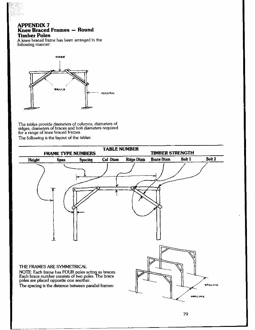
APPENDIX 7 Knee Braced Frames - Round Timber Poles A knee braced frame has been arranged in the following manner:
The tables provide diameters of columns, diameters of ridges, diameters of braces and bolt diameters required for a range of knee braced frames. The following is the layout of the tables:
TABLENUMBER FRAMETYPENUMBERS TIMBERSTRENGTH
Height Span SW&l Co1 Diam Ridge Diam Brace Diam Bolt 1 Bolt 2
THE FRAMES ARE SYMMETRICAL NOTE: Each frame has FOUR poles actin as braces. Each brace number consists of two
tl! oles. B he brace
poles are placed opposite one ano er. The spacing is the distance between parallel frames:
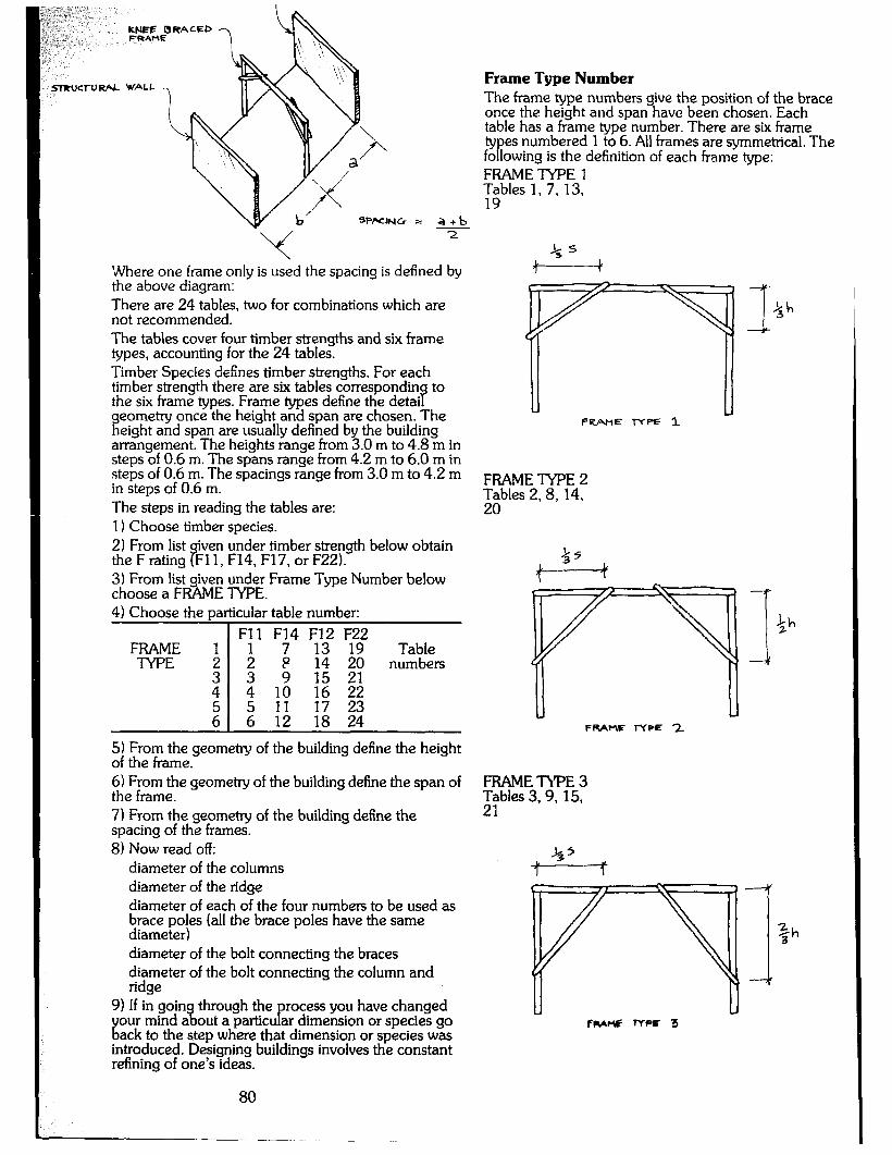
S?RUC~URP.L WALL
SPKING = a+b - -2
Where one frame only is used the spacing is defined by the above diagram: There are 24 tables, two for combinations which are not recommended. The tables cover four timber strengths and six frame types, accounting for the 24 tables. Timber Species defines timber strengths. For each timber strength there are six tables correspondin
s to
the six frame types. Frame types define the detai geometry once the height and span are chosen. The height and span are usually defined by the building arrangement. The heights range from 3.0 m to 4.8 m in steps of 0.6 m. The spans range horn 4.2 m to 6.0 m in steps of 0.6 m. The spacings range from 3.0 m to 4.2 m in steps of 0.6 m. The steps in reading the tables are: 1) Choose timber species. 2) From list iven under timber strength below obtain the F rating Fl 1, F14, F17, or F22). a 3) From list given under Frame Type Number below choose a FRAME TYPE. 4) Choose the particular table number:
FRAME TYPE :
Fll F;4 ;I32 :292
; Table
P 14 20 numbers
: z 1: :65 ;: 65 5 6 11 12 18 17 24 23
5) From the of the frame.
geometry of the building define the height
6) From the geometry of the building define the span of the frame. 7) From the geometry of the building define the spacing of the frames. 8) Now read off:
diameter of the columns diameter of the ridge diameter of each of the four numbers to be used as brace poles (all the brace poles have the same diameter) diameter of the bolt connecting the braces diameter of the bolt connecting the column and ridge
9) If in goin our mind a %
through the recess you have changed
E out a particu ar dimension or species go P
ack to the step where that dimension or species was introduced. Designing buildings involves the constant refining of one’s ideas.
Frame Type Number The frame type numbers give the position of the brace once the height and span have been chosen. Each table has a frame type number. There are six frame types numbered 1 to 6. All frames are symmetrical. The following is the definition of each frame type: FRAMETYPE 1 y;bles 1, 7, 13,
FRAME TYPE 2 z;bles 2,8,14,
FRAWF TYPE ?.
I $h
FRAME TYPE 3 Ebles 3,9, 15,
80
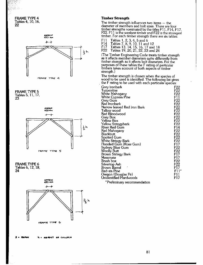
FRAME TYPE 4 gbles 4, 10,16,
A?PROK 450 n(el
c f-r LG.
c: .
a
:A 3 -’
1 FRbME TYPE 4
FRAMETYPE ;;bles 5, 11, 17,
FRAME TYPE 5
FRAMElWE6 SFbles 6, 12, 18,
APROS 450 mm
Timber Strength The timber stren
% h influences two items - the
diameter of mem et-s and bolt sizes. There are four timber stren F22. Fl 1 is t II
ths nominated by the titles Fl 1, F14, F17, e weakest timber and F22 is the strongest
timber. For each timber strength there are six tables: Fl 1 F14
Tables 1,2,3,4,5 and 6
F17 Tables 7,8, 9, 10, 11 and 12
F22 Tables 13, 14, 15, 16, 17 and 18 Tables 19,20, 21, 22, 23 and 24
(The Timber Envying Code treats timber strength as it affects mem er drameters quite differently from timber strength as it affects bolt diameters. For the pu
‘g oses of these tables the F rating of
P articular
tim ers takes account of both aspects o timber strength. ) The timber strength is chosen when the species of wood to be used is identified. The following list gives the F rating to be used with each particular species: Grey ironbark F22 Turpentine F22 White Mahogan
Py F22
White Cypress ine Fll Grey Gum F22 Red lronbark Narrow leaved Red lron Bark ZI Tallow wood . F22 Red Bloodwood Grey Box Yeliow Box Yellow Stringybark River Red Gum Red Mahogany Blackbutt S otted Gum dil ite Stringy Bark Flooded Gum (Rose Gum) S d
dney Blue Gum oolly Butt
Brown Stringy Bark Messmate Brush box Silver-to Ash Brown arrel f; Radi&a Pine Ore Uni %
on (Douglas Fir) entified Hardwoods
l Preliminary recommendation
F22 F22 F22 F22 F14 F22 F22 F22 F22 F17
‘
F22 F22 F17 F17 F22 F22 F17 Fll’ Fll F17
FRAME +YPE b
sm *AN h a nr~+wt OC CoWf’lN
81
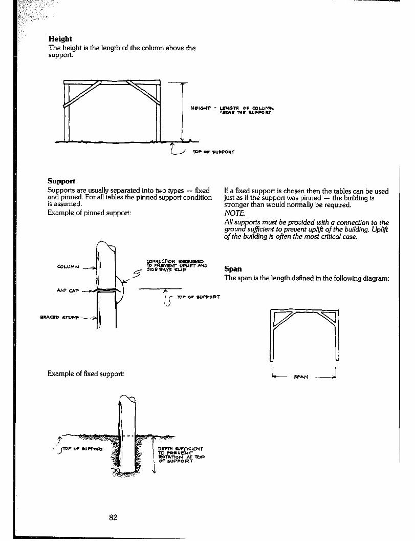
Height The height is the length of the column above the support:
TW= OC SUPPORT
support support Supports are usually separated into two types - fixed Supports are usually separated into two types - fixed and pinned. For all tables the pinned support condition and pinned. For all tables the pinned support condition
If a fixed support is chosen then the tables can be used If a fixed support is chosen then the tables can be used
is assumed. is assumed. just as if the support was pinned - the building is just as if the support was pinned - the building is stronger than would normally be required. stronger than would normally be required.
Example of pinned support:
-
NOTE. All sup otis must be provided with a connection to the gmun B sufficient to prevent uplift of the building. Uplift of the building is often the most critical case. I
in I CIJWECI~ON REWIRED COLWI N TO PREVENT UPUFT AND
5 5lDC WAY5 SUP spa
The span is the length defined in the following diagram:
Example of ked support:
T oc S”PPoRr
l- SPAI- -4
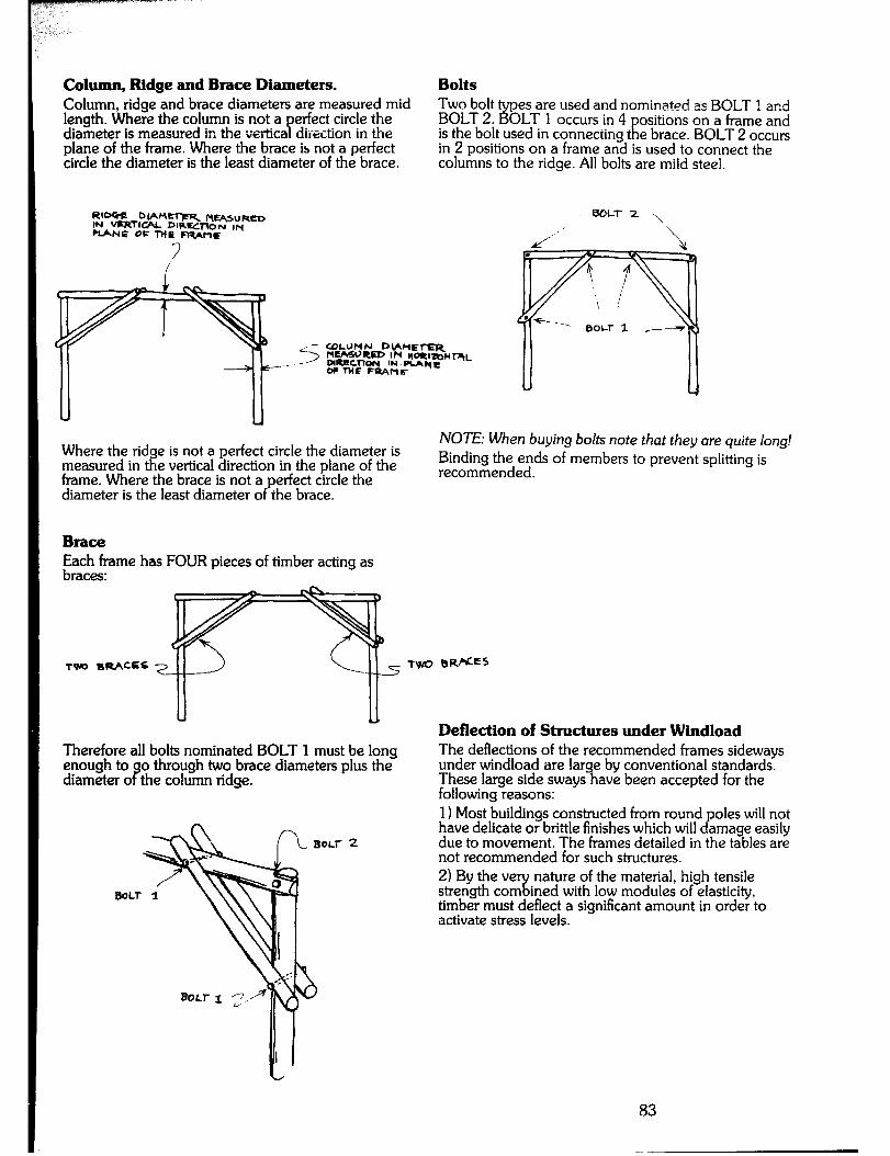
Column, Ridge and Brace Diameters. Bolts Column, ridge and brace diameters are measured mid Two bolt length. Where the column is not a
pes are used and nominated as BOLT 1 and
P erfect circle the BOLT 2. 3 OLT 1 occurs in 4
E ositions on a frame and
diameter is measured in the vertica direction in the is the bolt used in connecting t e brace. BOLT 2 occurs plane of the frame. Where the brace is not a perfect circle the diameter is the least diameter of the brace.
in 2 positions on a frame and is used to connect the columns to the ridge. All bolts are mild steel.
R’ocif otiM=m t4t%+SURCD IN VERrlcN DIREC~N ,M
BOLT2 \
-NC OK l-NE FIUrra /’ ’ \
Where the ridge is not a perfect circle the diameter is measured in the vertical direction in the plane of the frame. Where the brace is not a perfect circle the diameter is the least diameter of the brace.
NOTE: When buying bolts note that they are quite long! Binding the ends of members to prevent splitting is recommended.
Egh,f”rne has FOUR pieces of timber acting as
Therefore all bolts nominated BOLT 1 must be long enough to o through two brace diameters plus the diameter o 9 the column ridge.
Deflection of Structures under Windload The deflections of the recommended hames sideways under windload are large by conventional standards. These large side sways have been accepted for the following reasons: 1) Most buildings constructed from round poles will not have delicate or brittle finishes which will damage easily due to movement. The frames detailed in the tables are not recommended for such structures. 2) By the ve strength corn ‘4:
nature of the material, high tensile ined with low modules of elasticity,
timber must deflect a significant amount in order to activate stress levels.
83
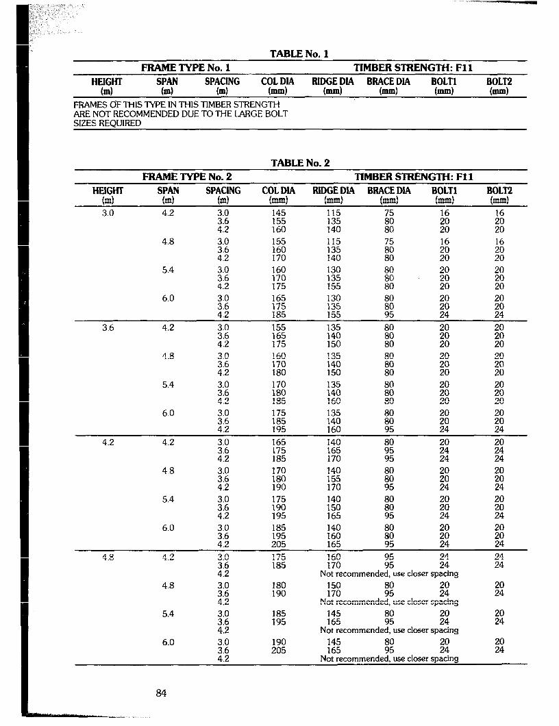
TABLENo. FRAME TYPE No. 1 TIMBER STRENGTH: Fll
HEIGHT SPAN spYf"G
COLDIA BOLT2 (4 bd m bd
RlqGEPlA BqCE;IA mm mm bd
FRAMES OF THIS IY’PE IN THIS TIMBER STRENGTH ARE NOT RECOMMENDED DUE TO THE LARGE BOLT SIZES REQUIRED
TABLE No. 2 FRAME TYPE No. 2 TIMBER STRENGTH: Fll
HEIGHT TY "'t"f""
BlDGEDlA BBACEDIA BOLT1 (ml m m bd (=I bd 3.0 4.2 3.0 145 115 z :fi 16
3.6 4.2 E :z 80 20 i%
4.8
5.4 z-: 160 130
4:2 E 135 155
16
go”
6.0 3.0 165 130 3.6 4.2 E ::z
2 24
3.6 4.2 3.0 155 135
E! E ;zi 4.8 3.0 160 135 80 20
3.6 4.2 % 2: isi ;:
5.4 3.0 170
Ei E :$I 160
6.0 ;z 175 4:2 :2
E % 160 95
4.2 4.2 i:: 165 140 175 165 :: ;: it
4.8 4.2 185 170 95 24 24
4.8
5.4
6.0
4.2
4.8
5.4
6.0
3.0 34::
::: 4.2
% 4:2
3:;
::: 4.2
Z:E 4.2
175 190 195
::z 205
:2
;;:
185 195
190 205
140 150 165
;: 24
% 165
ii ;ij
:% z; ;: Not recommended, use closer spacing
i% G! 2? Not recommended, use closer spacing
145 165 98: ;40 Not recommended, use closer spacing
145 165 %! ;: Not recommended, use closer spacing

TABLE No. 3 FRAME TYPE No. 3 TIMBER STRENGTH: Fl 1
HEIGHT TY
BIDGEDIA BBACEDLA BOLT1 BOLT2 (4 m Sp?crG m c?!zw bd bd (mm) bd 3.0 4.2 3.0 130 115
3.6 135 135 5; ;z 16
4.2 140 140 80 20 :: 4.8 3.0 135 115 2 16 16
3.6 140 4.2 150 1:; 80 % z
5.4 2; 140 115 16 16
150 135 155 140
lzi
E-i ;i 6.0 3.0 145 125
2; 155 165 135 140
2 16 16
80 % ;:
3.6 4.2 E 135 135 16 4.2 %
140 2 ;: 150 80 E 20
4.8 3.0 140 135
140
El 16 16
3.6 150 4.2 160 150 80 ;: El 5.4
3.0 145 3.6 155 ii; E 4.2 165 150 80
6.0 E z 135 140 z: %I 4.2 170 160 24 24
4.2 4.2 3.0 % 140 20 20
2 160 160 170 5: ii 4.8 E
24 % 24
:zi 170
5.4 155 140 165 150 :: c: ;i 175 165 95 24 24
6.0 3.0 1% 140 it 20 20
2; 180 150 165 95 22: $40
4.8 4.2
4.8
z:: 4.2 3.0
2;
160 165
160 170
160 170 E ;: Not recommended, use closer spacing
1% L E ;: Not recommended, use closer spacing
5.4
6.0
3.0 165 145 3.6 175 4.2 180 E
E 170 145
4:2 198:
85
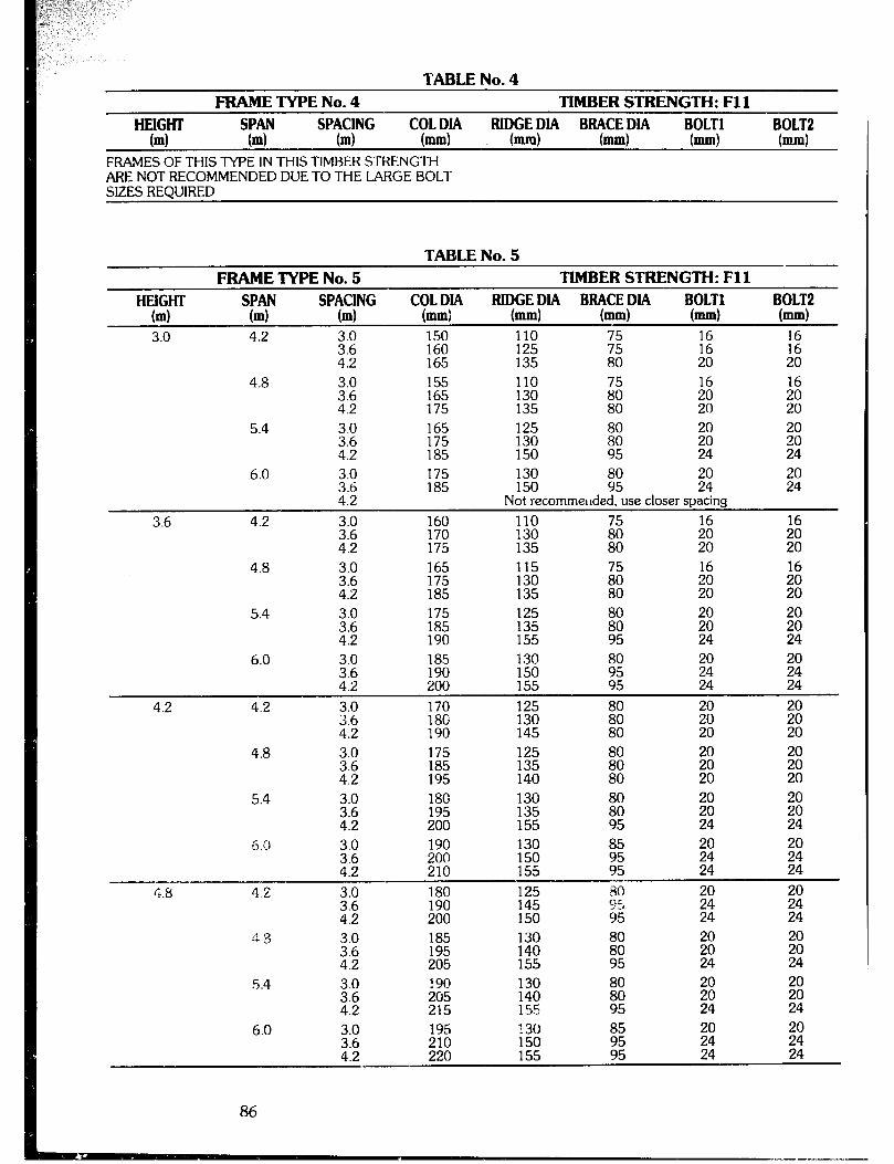
TABLE No. 4 FRAME TYPE No. 4 TIMBER STRENGTH: Fll
TGIW m TY m Sp?cjNG FUDGEDIA BBACEDIA BOLT1 BOLT2
m I-1 (-1 bd bd FRAMES OF THIS TYPE IN THIS TIMBER STRENGTH ARE NOT RECOMMENDED DUE TO THE LARGE BOLT SIZES REQUIRED
FRAME TYPE No. 5 TABLE No. 5
TIMBER STRENGTH: Fll HEiGHT
04
3.0
SPAN M
4.2
SPACING (ml
3.0 3.6 4.2
BIDGEDIA BBACEDIA BOLT1 BOLT2 (-1 h.4 (-1 b.4
150 110 75 160 125 2i
2 :z 165 135 20 20
4.8 :::
155 110 165 130 2
4.2 175 135 80 5.4 3.0
3.6 4.2
3.6
4.2
6.0
4.2
4.8
5.4
6.0
4.2
3.0 3.6 4.2 3.0 3.6 4.2 3.0
2 z::
4.2
3.0 Z
3.0 3.6 4.2
175 185
160 170 175 165
175 185 175
%
185 200 190
170 ;t:
130 150 E El Not recommellded, use closer spacing
110 130
At?
135
2
20 115 16
130 135
gj
ii 125 135 E z: 155 95 24
130 150 155
t: ;40 95 24
125 130 ii ;: 145 80 20
4.8 :: 80
;: 20
z: 20
5.4 2 180 130 El 20 195 135
4.2 200 155 24 ;:
6.0 2 190 130 85 150 El z 4.2 8: 155 E 24 24 --^
r,.8 42 Z:E :z 125 80
;:: gc, 95
ii Ei 4.2 200 24 24
i? 3 3.0 185
i:; 205 195
z: 80 z 155 ti 24
5.4 3.0 190 80
2 205 215
EFi
E z
1.5 24
6.0 3.0 195 130 3.6 210 150 ;: 4.2 220 155 24

TABLENo. FRAMETYPENo.6 TIMBERSTRENGTH:Fll
HEIGHT SPAN SPACING COLDIA RlDGEDlA BBACEDIA BOLT1 BOLT2 - _--- (4 (4 b) (=I bd bd (=I bd --
3.0 4.2 3.0 130 110 2; 140 145 115 130
E EJ E 75 16 16
4.8 140 110 145 115 5: 155 135 80
E 20
E 20
5.4 3.0 145 16 16
2 155 160
1;;
135 ;i E 6.0 Z:Z 155 120 16 16
160 135 4.2 170 140
II
;t :?I
3.6 4.2 E 140 110 4:2 155 150 130 135
2 E 8; 80 20 20
4.8 E 145 110 16 16 155 130
4.2 165 135 ?I Ei 5.4
Z:Z 150 160 115 135 4.2 170 140
6.0 160 115
170 :z
:z 4; 16
175 85 20 E
4.2 4.2 2: 150 125 160 130 z: 2 4.2 165 145 20 20
4.8 3.0 155 125 ::5 :% 130 140
E 85
;: 20
c: 20
5.4 3.0 160 16
2; 170 :i: ;: :; 180 140 90 20 ;t
6.0 i:: 165 130 g ;:
16
4.2 :E E 20 ;:
4.8 4.2 2: 20 4:2
::z ii: ;): 175 150 Ii 24
4.8 2: % 125 20 4.2 180 % ;t
z 24
5.4 170 180 is: 185 155
;t 24
6.0 3.0 130 100 20 2;
ii; E 100 100 20 24
zi 195 24
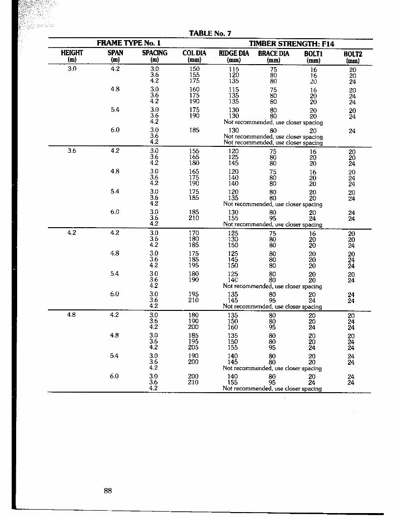
TAB LE No. 7 FRAME TYPE No. 1 TIMBER STRENGTH: F14
OLTl BOLT2 SPAN (ml
4.2
““t”~” m BlqGE p”
mm BYCEP” Bi
mm bd (=I
3.0 150 115 3.6 155 120 El i: ;: 4.2 175 135 80 20 24
HEIGHT (4
3.0
3.6
4.8
5.4
6.0
4.2
3.0 i:;
::: 4.2
3.0
2;
332 4.2
160 175 190
175 190
185
155 165 180
115 ii; 16 E 80 ;:
1% El 22: Not recommended, use closer spacing
130 80 20 Not recommended, use closer spacing Not recommended, use closer spacing
120 125 ii: ii 145 80 20
$40 24
El
24
4.8 3.0 165 120 i:; 175 190 140 140
16
;i
4.2
5.4
6.0
4.2
::: 4.2
i:: 4.2
3.0 3.6 4.2
175 185
185 210
170 180 185
120 135 ii ;ii Not recommended, use closer spacing
130 155 ;: ;: Not recommended, use closer spacing
2: l3; 16
GO 80 Ei
4.8
5.4
3.0 175 125 3.6 185 4.2 195 E-2
it 80
;: ;: 20 24
3.0 3.6 4.2
180 190
125 14C iit SE
Not recommended, use closer spacing
4.8
6.0
4.2
195 210
180 190 200
135 145 :: ;: Not recommended, use closer spacing
:zi ii: 160 95
4.8 3.0 185 135
2 205 195 E zi 24
5.4 190 200 140 145 iii: 22: Not recommended, use closer spacing
6.0 140 155 i: El
Not recommended, use closer spacing
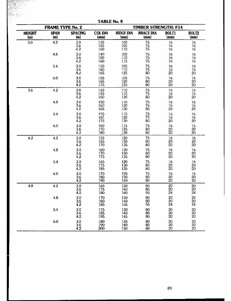
TABLE No. 8 FRAME TYF’E No. 2
SPAN sp?c$G (4 m
TIMBER STRENGTH: F14 BIDGEDM BBACEDIA BOLT1 BOLT2
bd (=I bd (mm) 4.2 E
75 E 16
4.8 3.0 140 100 75 3.6 150 110 4.2 160 115 E
iz i: 16 16
5.4 3.0 150 3.6 160 iy; i25
E E ii? 4.2 165 80 20 20
6.0 3.0 155 i05
::: 165 175 E
iz 80
16
E
3.6 4.2 3.0 145 110 75 3.6 155 115 75 E 1: 4.2 160 130 80 20 20
4.8
5.4
3.0 150
::; 160 165
6.0 E 160 170
4.2 180 4.2 4.2 3.0 155
2:; i% 4.8
z:: 160 170
4.2 175 5.4 3.0 165
3.6 175 4.2 185
6.0 3.0 170
2:: %
Ei 80
;; 16
20 ;:
4.8 4.2 165 130
:;3: 140 % ;i 160 24 24
4.8 3.0 170
25 :z 5.4
:E 195
6.0 3.0 180
89
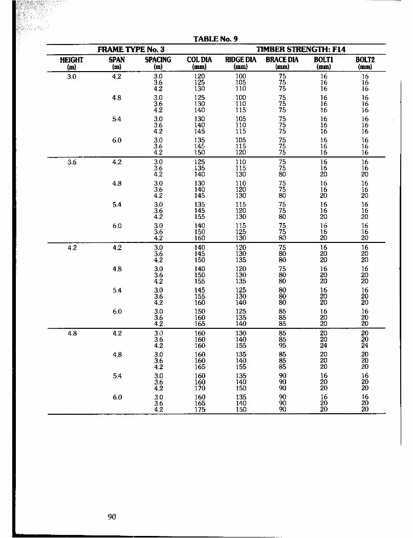
TABLE No. 9 - FRAMETYPENo.3 TIMBERSTRENGTH:F14
IT TY BOLT2 (ml m Sp?c!NG m
RlqGE PIA mm
B”t”Ep” mm (-1
3.0 4.2 3.0 120 100 ii:; 125 130 110 105
;g $ E 16
4.8 iig 125 100 130 110 E :z :: 140 115 75 16 16
5.4 3.0 130 105
E! 140 110 :: 145 115 16
6.0 ;:; 1;: 105 156 115 120
E :z 2 75 16 16
3.6 4.2 3.0 125 110 3.6 :%
115 ;: :E :2 4.2 130 80 20 20
4.8 3.0 E 110 3.6 120 E E E 4.2 145 130 80 20 20
5.4 3.0 135 2 i%
ii; 2 iii 130
;i 20 20
6.0 3.0 140 115 16
2 Ei % g
ii ;: 20
4.2 4.2 E 140 16
4:2 145 150
% 1:
135 20 ;: 4.8 140 120
150 130 155 135
5.4 145
:z ;:z 140
6.0 3.0 150 125 3.6 160 4.2 165 ::?I
iii;
4.8 4.2 3.3 160 ::: 1%
:% 155
iii;
4.8 % ii: ::z Ii 4.2 165 155 ii 53 20
5.4 160
% :iz ;i :: :: 150 90 20 20
6.0 i:: E 135 4.2 175 2:
8: 8; 20 20
90
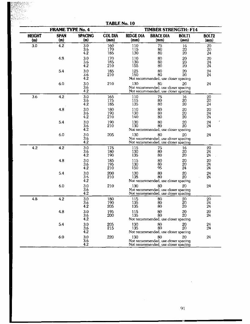
TABLE No. 10 FRAME TYPE No. 4 TIMBER STRENGTH: F14
TT “p”i” spYrG COLDIA RlDGEDIA BBACEDIA BOLT1 BOLT2
m m m (=I (-1 bd (-1 b4
3.0 4.2 $2 160 110 170 2 ;ii 4.2 185 1:; 80 20
4.8 3.0 170 110 3.6 185 130 4.2 210 155
5.4
6.0
3.0 3.6 4.2 3.0 3.6 4.2
185 210
210
125 20 150 :t 20 Not recommended, use closer spacing
130 80 20 Not recommended, use closer spacing Not recommended, use closer spacing
3.6 4.2 3.0 165 110 3.6 175 115 4.2 185 135
4.8 z:: 180 110 190 130
4.2 210 140 5.4 3.0
3.6 190 210
130 130
6.0 4.2 33.:
4.2
205 Not recommended, use closer spacing
130 80 20 Not recommended, use closer spacing Not recommended. use closer sDacina
24
. d
4.2 4.2 175 115 16 180 1% %
;40 190 24
4.8 3.0 185 115
2; 195 130 210 150
5.4
6.0
:.g 4.2 3.0
E
200 210
210
130 135 iFi ;ii Not recommended, use closer spacing
130 80 20 Not recommended, use closer spacing Not recommended, use closer spacing
22:
24
4.8 4.2
4.8
5.4
6.0
::: 180 190 115
4.2 205 ;:55 ::06
4.2 3.0 43:;
:::
4.2
195 200
205 215
220
115 80 135 80
;“o
Not recommended, use closer spacing 130 20 135
8 20
Not recommended, use closer spacing 130 80 20
Not recommended, use closer spacing Not recommended, use closer spacing
I: 24 20 24
24 24
24
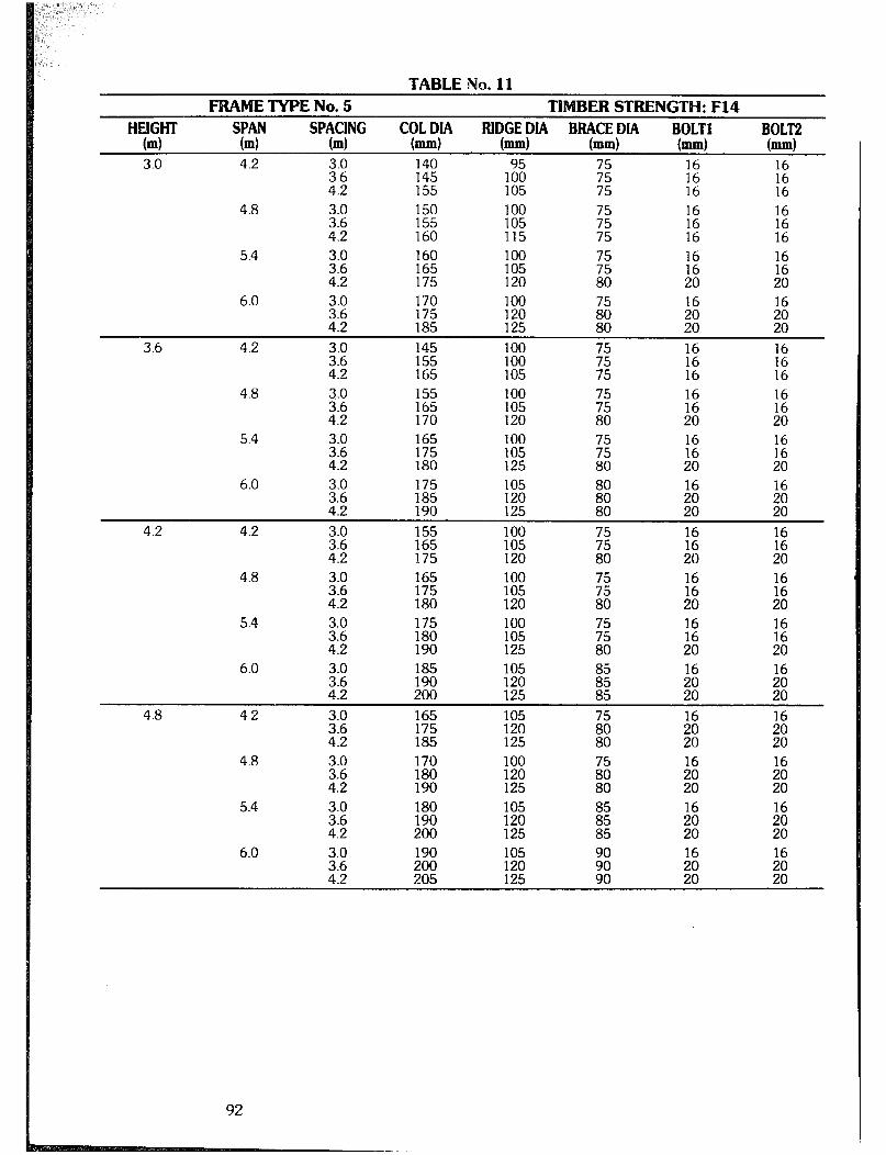
TABLE No. 11 FRAME TYPE No. 5 TIMBER STRENGTH: F14
HEIGHT TY Sp?cjNG
COLDIA (ml m m b-4
BI~GEPIA BRqCEp BOLT1 BOLT2 mm mm (-1 bd
3.0 4.2 3.0 140 3.6 145 1% Ei t: E 4.2 155 105 75 16 16
4.8 3.0 150 100 3.6 155 105 z 4.2 160 115 75
i: 16
5.4 3.0 160 3.6 165 E Ei :: E 4.2 175 120 80 20 20
6.0 3.0 170 100 16 16 3.6 175 120 4.2 185 125 22: iti
3.6 4.2 3.0 145 100 3.6 155 100 E 4.2 165 105 75
16
:z :2 16
4.8 ::: 155 100 165 105 ;z :66 12 4.2 170 120 80 20 20
5.4 3.0 165 100 3.6 175 105
;: z 16
4.2 180 125 80 20 8: 6.0 3.0 175 16 16
2 185 190
1;; iii:
125 80 ;i ;i
4.2 4.2 2:: 155 100 165 105 ;z El I2 4.2 175 120 80 20 20
4.8
5.4 3.0 175 100 2; 180 190 :;z
E :: E 80 20 20
6.0 3.0 185 105 3.6 190 120 El 2 ii 4.2 200 125 85 20 20
4.8 4.2 3.0 165 105 :Fi Ei 16
2 175 185 120 125 80 20 % 4.8 3.0 170 100 16
3.6 180 120
;tT
4.2 190 125 20 ;i 5.4
2: 180 190 105 120 :z 4.2 200 125 85
6.0 i:: 190 16 200
E ;: 2
4.2 205 125 90 20 %
92

TABLE No. 12 FRAME TYPE No. 6 TIMBER STRENGTH: F14
“Em SPAN
m (4 SpYfNG FUDGE DIA BRACE DIA BOLT1 BOLT2
m c?%a (mm) (mm) (-1 (mm)
3.0 4.2 3.0 120 85 3.6 130 100 ;z E 7; 4.2 135 105 75 16 16
4.8 3.0 130 3.6 135
lZ”o E E 12 16
4.2 145 105 75 16 16 5.4
3.0 135 100 3.6 145 105 ;z 4.2 150 110 75
16 16 16
KJ 16
6.0 3.0 140 100 3.6 150 105 ss: ii ;z 4.2 155 125 85 20 20
3.6 4.2 130 100 135 100 E 2 1: 145 105 75 16 16
4.8 iii 16
1: 16
5.4 2: 140 100 zig 16 16 1’2 4.2 % Kl 85 16 16
6.0 3.0 145 105 16 16 3.6 155 110
zi 16 16
4.2 165 125 90 16 16
4.2 4.2 3.0 140 100 16
2; 145 155 E
::
20 ;; 4.8 3.0 145
3.6 150 4.2 160
5.4 3.0 150 3.6 155 4.2 165
4.2 170 i
4.8 4.2 E 160 16 16
4:2 160 165
E zi
120 90 E ;t 4.8
5.4
3.0 160 100 3.6 160 120 4.2 170 125
160 105 100 165 115 100 175 125 100
6.0 3.0 160 100 100 2: 170 180 125 115 100 100
i: E 20 20

TABLENo. FRAMETYPENo.1 TIlMBERSTRENGTH:F17
HEIGHT SPAN spYG
COL DIA RIDGE DIA BBACE DIA BOLT1 (4 (ml
BOLT2 m (mm) (mm) (mm) (mm) (mm)
3.0 4.2 3.0 145 3.6 150
1E E 16 16
4.2 155 110 75 2 ;1:
4.8 3.0 155 1Ei 52 E 16
3.6 165 20 4.2 170 110 80 20 20
5.4 3.0 165 105 3.6 175 110 4.2 180 125
16
5:
6.0 3.0 E 105 3.6 125 % E 4.2 195 125 95 24
3.6 4.2 3.0 150 100 16 3.6 155 115 2 :2 4.2 165 120 80 20 22:
4.8 3.0 160 105 3.6 170 110 4.2 175 115
5: 1: 80 20
16
;ti
5.4 3.0 170 105 3.6 180 115 2 16
;i 4.2 185 130 80 ;Ei 24
6.0 3.0 180 110 16 20 3.6 190 125
z;
4.2 200 130 80 ;: E
4.2 4.2 3.0 160 115 3.6 170 120 ;z i:
16
4.2 175 125 80 20 Ei
4.8 3.0 165 115 16
3.6 175 120 i; ;g
4.2 180 125 80 20 ;z 5.4
3.0 180 115 3.6 185 120 z; 4.2 195 135 80
zi 24
6.0 3.0 190 115 3.6 195 130 %i ;: z 4.2 205 135 80 20 24
4.8 4.2 3.0 170 125 3.6 180 135 E h: 16
4.2 190 140 80 20 :: 3.0 175 125 3.6 185 130 4.2 190 145
16
;: ;: 24
5.4 3.0 185 125 16 3.6 190 130 ;i
;t 4.2 200 140 24
6.0 3.0 195 125 3.6 200 135 ifi ;: ;i 4.2 210 140 95 24 24
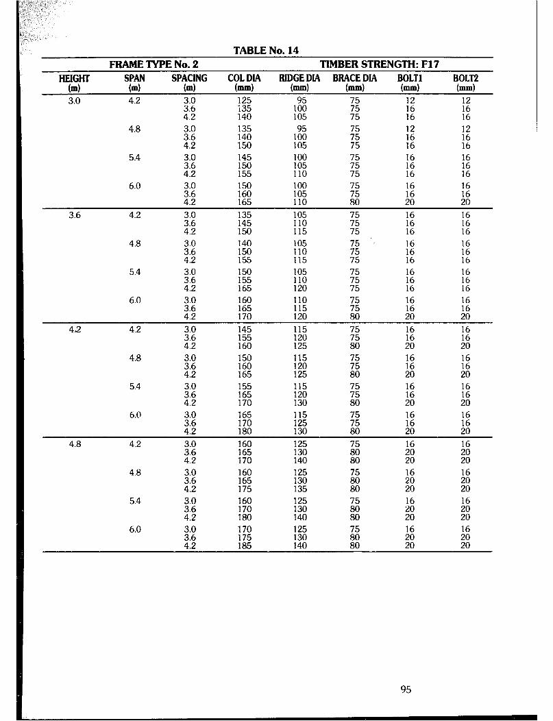
TABLENo. FRAMETYPENo.2 TIMBERSTRENGTH:F17
HEIGHT TY
SPACING "?=P
Bl;GEfIIA BItACEDiA BOLT1 BOLT2 (4 m M mm bd (=I bd 3.0 4.2 3.0 125 95 75 12 12
3.6 i35 4.2 140
4.8 135 140
4.2 150 5.4 3.0 145
25 150 155
ii! E 16 16
05 75 16 16
E 75
1: 16
6.0 3.0 1.50 100 3.6 160 105 2 iz 2 4.2 165 110 80 20 20
3.6 4.2 3.0 135 3.6 145 K!i E E :z 4.2 150 115 75 16 16
4.8 3.0 140 105 ’ 3.6 150 110 E 4.2 155 115 75
:z 16
1: 16
5.4 3.0 150
3.6 155
% E 1: 16
4.2 165 120 75 16 i: 6.0 3.0 160 110 16 16
3.6 165 115
E
4.2 170 120 80 % ::
42 4.2 3.0 145 115
i:; 155 160 120 125 E 80
2 20
16
:;
4.8 2 :z 115 120 ;z 2 ;z 4.2 165 125 80 20 20
5.4 3.0 155 115 25 :% 120 130
EJ 80
E 20
6.0 2 165 115 170 125 ;z E 2 4.2 180 130 80 20 20
4.8 4.2 3.0 160 125 3.6
1% :% :z iii
4.2 80 20 4.8
5.4
160 165 175
33:: 160 170 1:; ii; 4.2 180 140 80
6.0 ::: 170 16 16 175
;z
4.2 185 140 ;: it
95
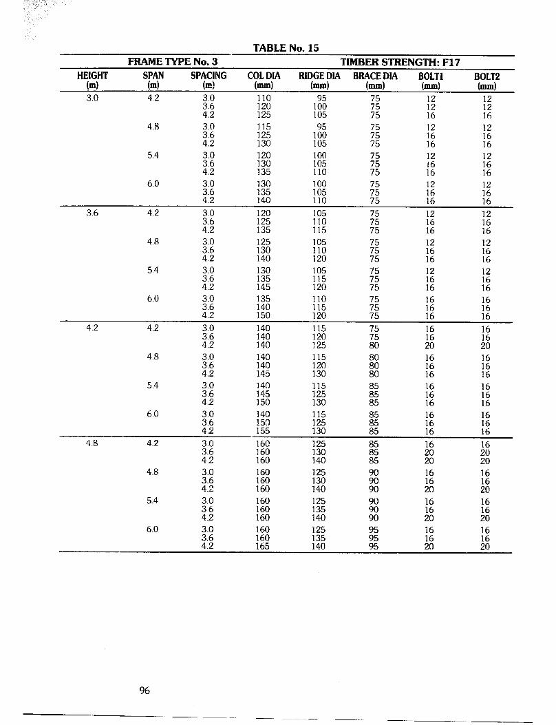
TABLENo. F ETYF'ENo.3 TIMBERSTRENGTH:F17
HEIGHT (ml "YY
RlDGEDIA BBACEDIA BOLT1 BOLT2 m spY,G m, "gi)" b.4 bd bd bd
3.0 4.2 3.0 110 3.6 120 250 E :E :; 4.2 125 105 75 16 16
4.8 3.0 115 3.6 125 lF?i ;z 2 :i 4.2 130 105 75 16 16
5.4 3.0 100 3.6 % 105 E 4.2 135 110 75
6.0 3.0 130 100 3.6 135 105 Ei E :: 4.2 140 110 75 16 16
3.6 4.2 3.0 120 105 3.6 125 110 7’: kz E 4.2 135 115 75 16 16
4.8 3.0 125 2; 130 140
% E E 1: 120 75 16 16
5.4 3.0 130 105 3.6 135 115 ;z Ea E 4.2 145 120 75 16 16
6.0 3.0 135 110 16 3.6 140 115 ;z 4.2 150 120 75 ;z
1: 16
4.2 4.2 3.0 140 115 3.6 140 120 E 12 :: 4.2 140 125 80 20 20
4..8 3.0 140 115 3.6 140 120 iii: 12 4.2 145 130 80 16
5.4 3.0 140 3.6 145 ii: 4.2 150 130
;2 16
6.0 3.0 140 115 3.6 150 125 1: E 4.2 155 130 16 16
4.8 4.2 3.0 160 3.6 160
z;
4.2 160 140
I?$ 16 16
;: %
4.8 3.0 160 125 3.6 160 130 z: 12 :: 4.2 160 140 90 20 20
5.4 2: 160 160 :E ;: 16 12 4.2 160 140 90 8: 20
6.0 3.0 160 125 3.6 160 12 1: 4.2 165 ii: 20 20
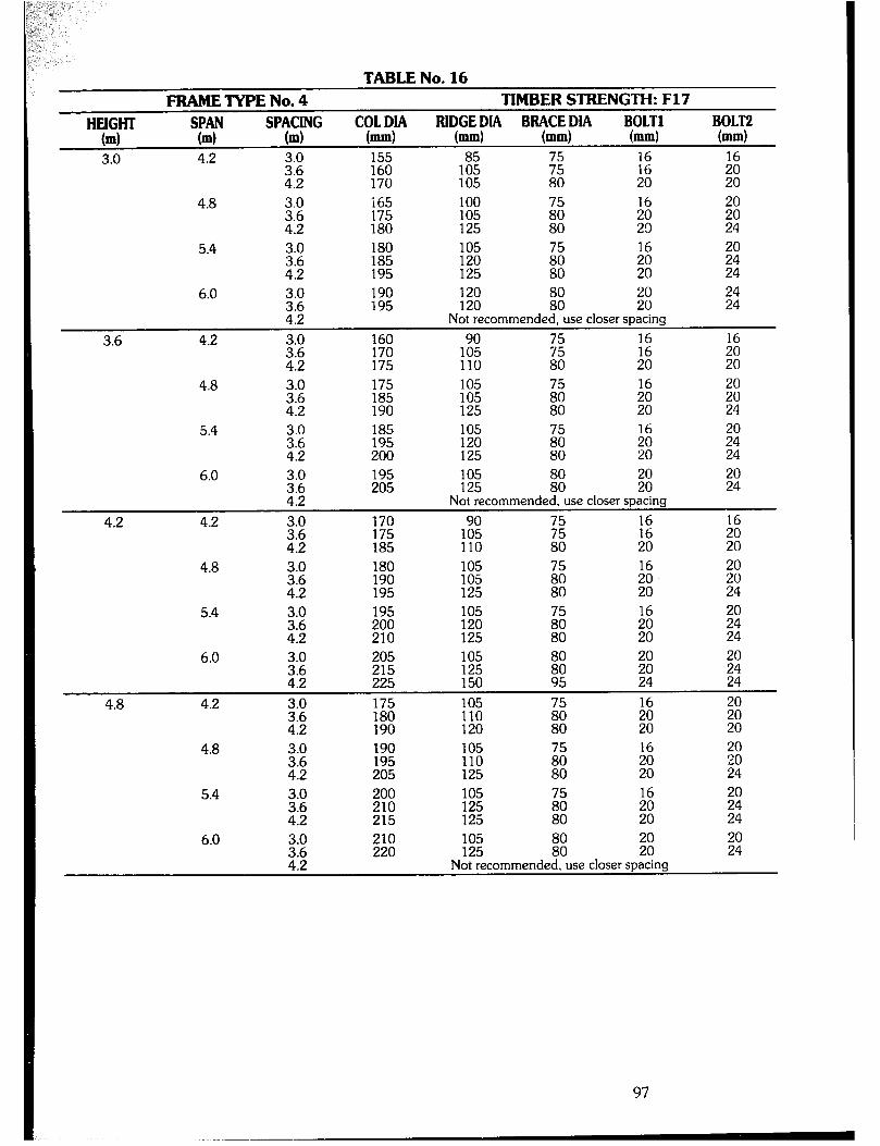
TABLE No. 16 FRAME TYPE No. 4 TIMBER STRENGTH: F17
“YGY m “p’i” IUDGEDIA BRACEDIA BOLT1 BOLT2
m sptcf”G m “%Y m4 (-1 (=I (mm) 3.0 4.2 Z:E Ez 1% 2 E 16
4.2 170 105 80 20 2
4.8 3.0 165 100 3.6 175 105 ; ii ;: 4.2 180 125 2!l 24
5.4 3.0 180 105 3.6 185 120 2 16 z40 4.2 195 125 80 2 24
3.6
6.0
4.2
3.0 190 2; 195
2: 160
4.2 E
120 120 iii: :: Not recommended, use closer spacing
1E 75 2 75
110 80 20 4.8 3.0 175 105
2; :t; 105 z: 125 80
5.4 3.0
E
:: ;i 20 24
Ei 24
4.2
6.0
4.2
3.0 3.6 4.2 3.0
2;
195 205
E
185
105 125 :: El Not recommended, use closer spacing
19005 E 16
110 80 :: 4.8 i:: 180 105
190 105 4.2 195 125
5.4 195 105 16 z 120 125 ;:
$40 24
6.0 3.0 205 105 20 ::t 215 225 125 150
iii z 95 :I? 24
4.8 4.2 1;; 105 110 ;: 8 190 120 20 20
4.8 3.0
25 E :% 205 125
5.4 200 105 210 125 215 125
16
z:
20 20 24
El 24
6.0 210 220 KE E $00
Not recommended, use closer spacing
97
-~
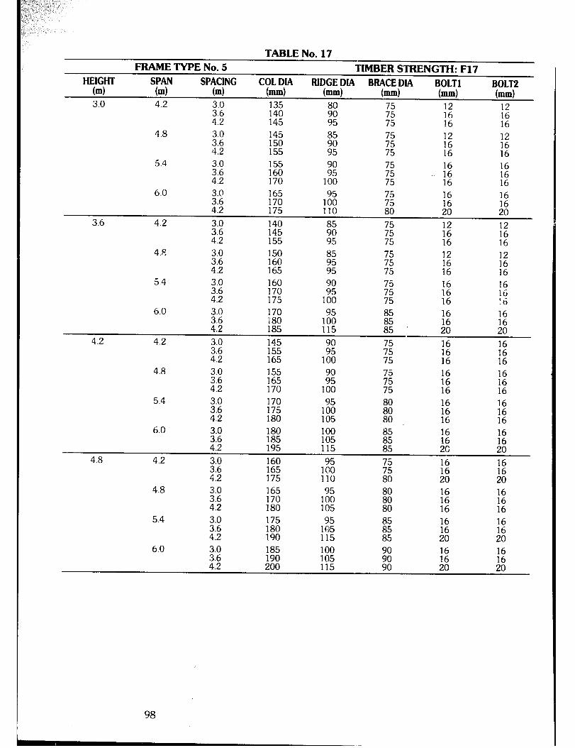
TABLE No. 17 FRAME TYPE No. 5 TIMBER STRENGTH: F17
HEIGHT SPAN (ml (4 sp?ct"G
COLDIA BOLT1 m b.4
FUlXCiHA ByCE/MA BOLT2 mm bd b.4
3.0 4.2 3.0 135 3.6 140 GE ;55 12
4.2 145 ;:
95 75 2 16
4.8 3.0 145 3.6 150 :; ;z 4.2
i: 155
:: 95 75 16 16
5.4 3.0 155 3.6 160 E ;: 4.2
i66 170
E 100 75 16 16
6.0 3.0 165 3.6 170 1:: ;55 1: 4.2 175
:z 110 80 20 20
3.6 4.2 3.0 140 3.6 145 982 ;: 4.2
E E 155 95 75 16 16
4.E 3.0 150 3.6 160 9855 $1 1; 4.2 165
162 95 16 16
5.4 3.0 160 3.6 16
170 z: ;z 1: 4.2 175
16 100 75 16 1 - .o
6.0 3.0 170 3.6 180 1% :: 1; 4.2 185
:: 115 85 20 20
4.2 4.2 3.0 145 3.6 155 Ti 2 1: 4.2
iz 165 100 75 16 16
4.8 3.0 155 3.6 165 ;: E 4.2
i: :E 170 100 75 16 16
5.4 3.0 170 3.6 175 1% 2 4.2 180
ii2 105
i?; 16 16
6.0 ::: 180 100 185 105 i: ::
4.2 i:
195 115 85 2G 20 4.8 4.2 3.0 160
3.6 165 1:: E 2 4.2
;2 175 110 80 20 20
4.8 3.0 165 3.6 170 1:; it E 4.2 180 105 80 16
5.4 3.0 3.6 El 1% E E 16
4.2 16
190 115 85 20 20
6.0 3.0 185 100 3.6 190 105 iii 12 ;fi 4.2 200 115 90 20 20
98
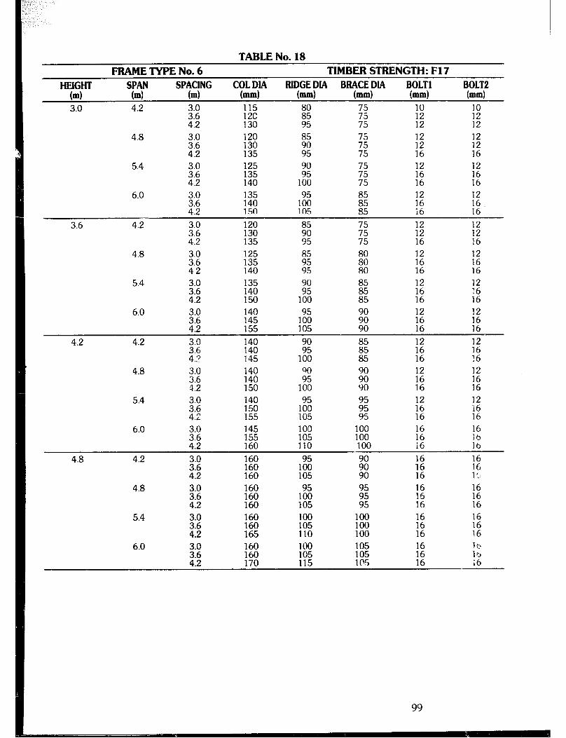
TABLENo. FRAMETYPENo.6 TlMBERSTRENGTH:F17
HYGlm TT spYrG BIDGE DIA BRACE DIA BOLT1 BOLT2 m m m (mm) (mm) (mm) (mm)
3.0 4.2 2 115 12c E E :;
4.2 130 95 75 12
4.8 3.0 120 85 3.6 130 E 4.2 135 ;Lz 75
5.4
6.0 3.0 135 3.6 140 1% EE 4.2 150 10.5 85
3.6 4.2 3.0 120
2; E ;Fi E 95 75
4.8 3.0 125 E 80
95
16 16
:; 12
16 :z
E E 16 16 12 12 :; 16 16
E 12
16
5.4 3.0 135 3.6 140 ;z iii2 :2 2: 4.2 150 100 85 16 16
6.0 140 145 19050 2 :: E 155 105 90 16 16
4.2 4.2 ::o” 140 ;: E 12 12 140 4.2 145 100 85 :: !Z
4.8 3.0 140 3.6 140
z: ii! 12 12
4.2 150 100 90 t: :z 5.4 3.0 140
::5 1E
19050 E ;2 12 ‘16
105 95 16 16 6.0 3.0 145 100 100
3.6 155 105 100 4.2 160 110 100
4.8 4.2 30 -.- 1El 2 16
I 2 :z: 160 105 90 1;
:z 16
16
i:
4.8 3.0 160 2: :i:
19050 ;z :: :2 105 95 16 16
5.4 2;
160 100 100 I 160 105 100 i: iii
165 110 100 16 16 6.0 3.0 160 100 105 15
2: 160 170 105 115 105 1@5 1 5
16
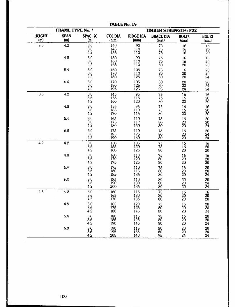
--
- .- FRAME TYPE No. 1 -- TIMBER STRENGTH: F22 HEIGHT
7T SPACkliG COL DIA BIDGE DIA BBACE DIA BOLT1 BOLT2
(ml m (4 (mm) (-1 bd bd (ml -- 3.0 4.2 3.0 140 90 16
3.6 145 110
;; 2
4.2 155 110 75 16 ;Ei 4.8 3.0 150 16
3.6 160
IT”0 2 1:
4.2 165 110 80 20 8 5.4 3.0 160
3.6 170 % 4.2 180 125
;z 24
TABLE No. 19
6.0 3.0 170 105 2; 180 195 125 125
z: ;: 24 24
3.6 4.2 3.0 145 3.6 155 ,755 75 2
E E 4.2 160 120 20 20
4.8 3.0 3.6 4.2
155 95 165 110 170 115
:: 20
16
El
5.4 3.0 165 110 16 3.6 175 llr, 20 % 4.2 180 130 20 24
6.0 ::E! 175 110 16 185 125 2 ::
540 4.2 190 130 80 24
4.2 4.2 3.0 150 105
3.6 155 120
2 :z 16
4.2 160 125 80 20 zi 4.8 3.0 160 110 ii: 16 16
25 170 175 120 125 80 ;: Iti 5.4 3.0 175 110
3.6 180 115 4.2 185 135
b.G ::: 185 110 20 190 130 E 4.2 200 135 % 24
48 4.2 3.0 160 115 16 16
22” 165 170 130 135 % z: 4.8 3.0 165 120
3.6 :z 125 4.2 145
20 30 24
5.4 3.0 180 16 20
E 185 190
;:z
145 ;ii :: 6.0 E E 1;: ii ;: 20
4.2 205 140 95 24 ;:

TABLENo. FRAMETWENo.2 TIMBERSTRENGTH:F22
dew TY SptCfNG "?ZU IUDGE DL! BRACE DIA BOLT1 BOLT2
m m m b4 (-1 (m.4 bd
3.0 4.2 33:: 120 85 75 125 1%
75 :: E 4.2 130 75 16 16
4.8 3.0 130
i:; ;i; z:
100 5.4 3.0 140
2; 145 E! 150 100
E 16
ii 16
::: 16
6.0 2 145 155 1% E :z 1: 4.2 16C 115 80 20 20
. 3.6 4.2 3.0 125 16
;:g 130 140 19050 E 105 75 2
:z 16
4.8 3.0 135 3.6 140 19050 E 12 2 4.2 150 110 75 16 16
5.4 3.0 145 - IUU ^^ 75 3.6 150 105 :: 1: 4.2 155 110 77: 16 16
6.0 3.0 155 100 2 iz 16
3.6 160 105 4.2 165 115 80 20 :E
4.2 4.7 3.0 140 105 it; 140 145 125 110
E i: 2 80 20 20
4.8 2
140 105 145 110 2
4.2 150 125 80 5.4 3.0 150
43:; E E 120
12 20
EJ 20
2 20
:z 20
6.r 3.0 160 110 43:: % 115 120
;zl :i E 80 20 20
4.8 di.2 160 115 16 16 160 ‘160 E ;: %
4.8 3.0 160 115
2; :FJ: 125 130
16
;: 5.4 3.0 160 :4: ;; ;: 16
Z:E 165 160 130 80 20 ;: 6.0 2: 165 :E 16 16
170 4.2 175 130 E * 22:
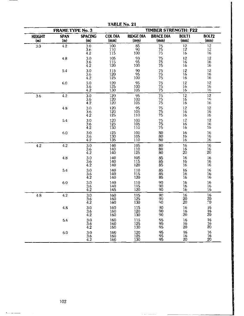
TABLE No. 21 - ETYPENo.3 TIMBER STRENGTH: F22
FY* m TY m ““?“f”” Y=? BIDGE DIA BBACE DIA
m (-1 bd y:z; BOLT2 (=I
3.0 4.2 3.0 100 ;z 75 12 3.6 110 5: E
;: 4.2 115 100 16
4.8 E :E 75 16
5.4 3.0 115 3.6 120 E E E :E 4.2 125 100 75 16 16
6.0 2 120 75 125 E
:: :: 4.2 130 16 16
3.6 4.2 3.0 ;20 95 E :: 12
3.6 120 100 4.2 120 105 75 16 E
4.8 3.0 120 75 12 3.6 19055 E 4.2 :;: 110 E E 16
5.4 3.0 120 100 3.6 125 105 E E E 4.2 130 110 75 16 16
6.0 3.0 125 100 25 1% 105 110
s8: 80
1: 16
16
E
4.2 4.2 3.0 140 105 2:; 140 140 110 125
:iz 2 20 20
4.8 3.0 140 105
2 140 140 115 120 i66 16
:66 16
5.4 ::: 140 110 140
4.2 140 E i: 16
6.0 3.0 140 110 90 16 16
3.6 140 4.2 145 2: 2 E i: 4.8 4.2 3.0 160
3.6 160 2; 4.2 160 130
4.8 :::
160 115
4.2 :z E 5.4 2 160
160 1;: Liz E E 4.2 160 130 95 20 20
6.0 3.0 160 16 3.6
:s: 2 22 4.2 z 130 95 ;; 20
102
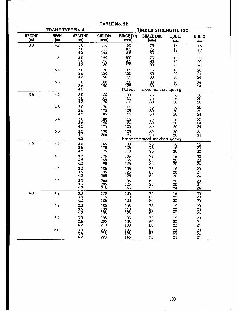
TABLENo. FRAMETYPENo.4 TlMBERSTRENGTH:F22
HEIGHT ST
SPACING COLDIA BIDGEDM BBACEDIA BOLT1 BOLT2 (ml m (4 bd (ml (mm) bJ.4 (-1 3.0 4.2 3.G 150
2 155 165
1% 7’: :: 16
105 80 20 ;: 4.8 3.0 160 100
3.6 170 1;:
2 4.2 180 80
16
z ;i 24
5.4 3.0 170 3.6 180
::2 El 16 ;: 4.2 190 ;25 80 $0” 24
6.0 3.0 180 120 2; 190 125
El 20 24 20 24
Not recommended, use closer spacing
3.6 4.2 3.0 155 _
3.6 165
1:: ;zl :i 16
4.2 170 110 80 20 22;
4.8 2: 170 16 175 1:: 4.2 185 125
;3 ;i
;Fj
5.4 3.0 180 105 20 3.6 190 120
I95 125
58 :i
4.2 20 ;t
6.0 3.0 190 105 3.5 200 125 E z $5: 4.2 Not recommended, use closer spacing
4.2 4.2 3.0 165 16 3.6 170
190: E E
4.2 175 110 80 20 ;:
4.8 3.0 175 3.6 185 E 4.2 190 125
5.4 3.0 185 105 3.6 195 2 4.2 205
E 80
16
El
;: 24
6.0 3.0 200 105 3.6 205 125 i% s: El 4.2 215 145 95 24 24
4.8 4.2 3.0 170
2; 175 % is
16
El %
185 120 20
4.8 3.0 180 105 16 3.6 190 110 2 ;: 4.2 195 125 80 2 24
5.4 E 195 105 4:2 200 210 125 130
:i E 20 24
6.0 3.0 205 105 ::5 ;;i 1::
i: 24
103

TABLENo. FRAMETWENo.5 TIMBERSTRENGTH:F22
COLDIA RlqGEPlA ByCEFlA BOLT1 (mm) mm mm bd
3.0 4.2 3.0 130 2; 135 140
2 77: 1: ‘? 95 75 16 k
4.8 2:
140 145
4.2 150 5.4
6.0 3.0 155 2 155 170
99: ;z ::: 110 20 20
3.6 4.2 3.0
3.6
ii: 2 12 12
4.2 150
;i
75 E I2
4.8 3.0 145 80 2 160 155 zz
E E 2 75 16 16
5.4 3.0 155 90 75 16 16
43:: 170 165 1% 75 75 t66 !Ei
:z 16
6.0 20 90 85 16 2
:z 1:: 8855 :06
TE 180 20
4.2 4.2 3.0 140 90 2; 150 155 95 95
;2 7c
:zI 2 16 16
4.8
5.4
3.0 150 90 3.6 4.2 E E
E 99: 175 100
:: 16 16
:66
;66 16
6.0 3.0 3.6
1:: 2 90 ;;
:: 2 4.2 185 115 20 20
4.8 4.2 El 160 ‘30 :z
95 77: :: :66 4.2 110 80 20 20
48 ;E 5.4 ;:; 170 90
:Ei 1E :z 2 20 20
3.0 160
2; 165 99: 170 100
6.0 180 16
:E 1% E 16 115 20 20
104
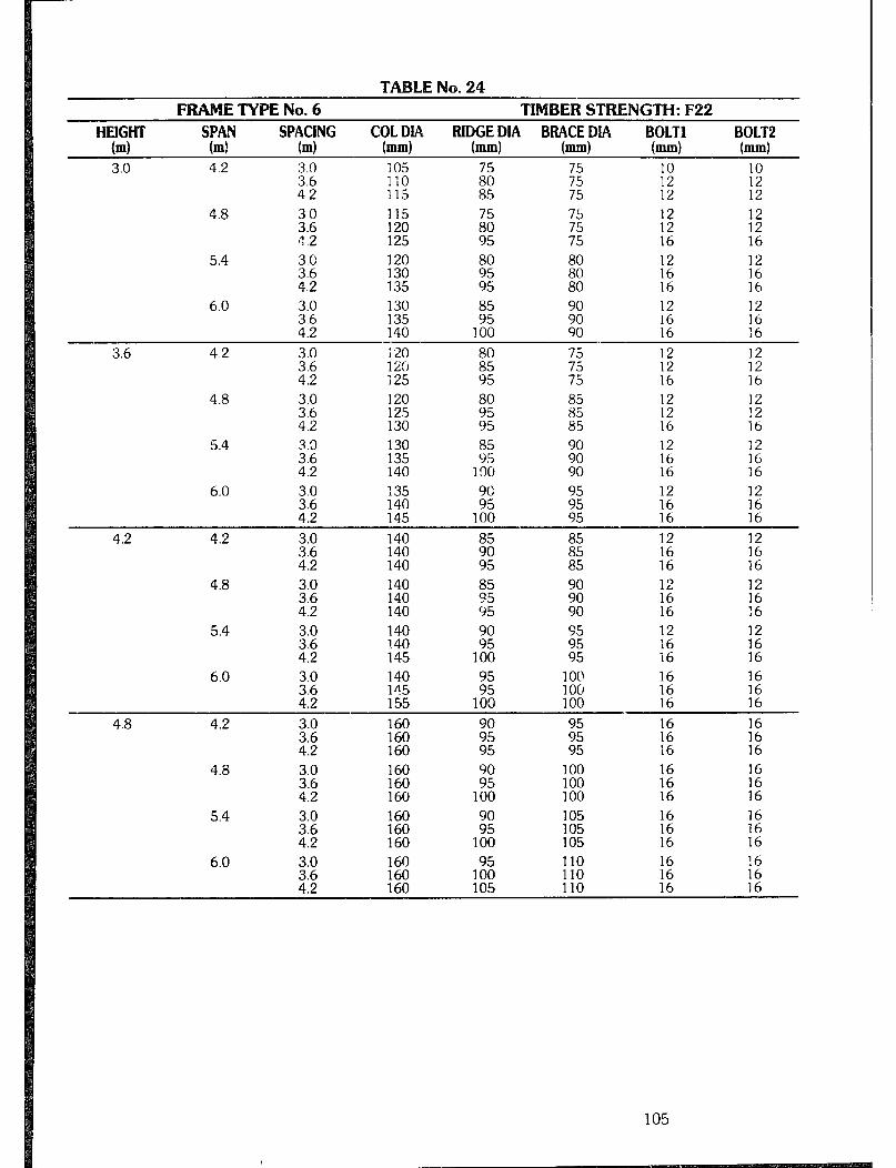
TABLENs. F ETYPENo.6 TlMBERSTRENGTH:F22
SPAN (ml
SPACING RIDGEDM BBACEDM BOLT1 BOLT2 bd c?k!i!)* (mm) (mm) hnm) bun)
3.0 4.2 3.0 3.6 4.2
4.8 z.: 4 .2
105 :Fi 85
110 115 115 120 125
E 12 12
75 16 16
iii 16
5.4 3.0 120 3.6 130 4.2 135 95 80 16
E zi 12 16 100 90 16
6.0 3.0 130 3.6 135 4.2 140
3.6 4.2 3.0 i20 3.6 l%:i
E ;: 12 12 12 12
4.2 125 95 75 16 lb
4.8 3.0 120 2 125 130
t: 95
12
:: 5.4 130 E 12
135 163
16 140 16
6.0 3.0 135 3.6 140 E E :: E 4.2 145 100 95 16 16
4.2 4.2 3.0 140 3.6 140
CFi E 12 12 16
4.2 140 95 85 1:
16
4.8 3.0 140 85 3.6 140 45 ;: 12 :2
E 4.2 140 95 90 16
5.4 3.0 140 3.6 140 E z 12 16 :: 4.2 145 100 95 16 16
6.0 3.0 140 3.6 145
100 100
16 16
4.2 155 100 100 16 16
4.8 4.2 3.0 160
E Ezii ;: E ;: 1:: 95 95 16 16
4.8 i:: 160 160
;kz 100 16
4.2 160 100 TE
i:
16 :z 5.4 3.0 160 105 16
3.6 4.2 %
;:
105
2
100 105 16 2 6.0 160 110
160 19050 110 160 105 110
:z :z 16 16
105
i
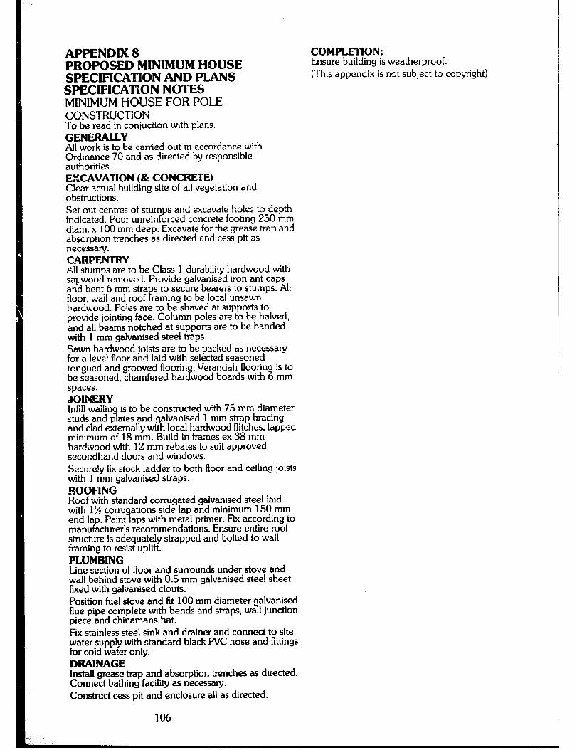
APPENDIX 8 PROPOSED MINIMUM HOUSE SPECIFICATION AND PLANS SPECIFICATION NOTES MINIMUMHOIJSEFORPOLE CONSTRUCTION To be read in conjuction with plans. GENEBALLY All work is to be carried out in accordance with Ordinance 70 and as directed by responsible authorities. EXCAVATION (& CONCRETE) Clear actual building site of all vegetation and obstructions. Set out centres of stumps and excavate holes to depth indicated. Pour unreinforced ccncrete footing 250 mm diam. x 100 mm deep, Excavate for the grease trap and absorption trenches as directed and cess pit as necessa y. CARPENTRY ~!l stumps are to be Class 1 durability hardwood with sapwood removed. Provide galvanised iron ant caps and bent 6 mm stra s to secure bearers to stumps. All floor, wail and roof !c aming to be local unsawn hardwood. Poles are to be shaved at supports to provide jointing face. Column poles are to be halved, and all beams notched at supports are to be banded with 1 mm galvanised steel traps. Sawn haidwood joists are to be packed as necessary for a level floor and laid with selected seasoned tongued and grooved floor-in . Verandah flooring is to be seasoned, chamfered har if wood boards with 6 mm spaces. JOINERY Infill walling is to be constructed with 75 mm diameter studs and plates and galvanised 1 mm strap bracing and clad externally with local hardwood flitches, lapped minimum of 18 mm. Build in frames ex 38 mm hardwood with 12 mm rebates to suit approved secondhand doors and windows. Secure!y fix stock ladder to both floor and ceiling joists with 1 mm galvanised straps. ROOFING Roof with standard corrugated galvanised steel laid with 1% conugations side lap and minimum 150 mm end la . Paint laps with metal primer. Fii according to manu acturer’s recommendations. Ensure entire roof P structure is adequately strapped and bolted to wall framing to resist uplift. PLUMBING Line section of floor and surrounds under stove and wall behind stove with 0.5 mm galvanised steel sheet fixed with galvanised clouts. Position fuel stove and fit 100 mm diameter alvanised flue pipe complete with bends and straps, wa 1 junction 9 piece and chinamans hat. Fii stainless steel sink and drainer and connect to site water supply with standard black PVC hose and fittings for cold water only. DRAINAGE Install grease trap and absorption trenches as directed. Connect bathing facility as necessary. Construct cess pit and enclosure all as directed.
106
COMPLETION: Ensure building is weatherproof. (This appendix is not subject to copyright)
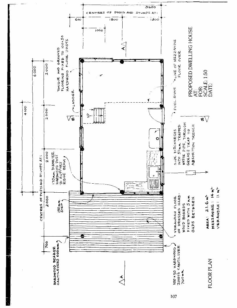
CE~TRES OF P’=Ts AND STUMPS A’T:
I-----+ 1 .___
600 I BOO I800
qv, ;$ O-
a-0 UOb
%I- d OAO -- di!JO asi
I - -__- 1060
0
u: z-7 P v) -1 w 3
r 2
V ____ ---- ----_- ---__ I
---A e-1
0. 3-m
m
. I
I i
.\ ._---_-- 1
Lt.
r -v a
-- - 1 i, ’ i t - -2 - -
- 1L w :---y
- - -
107

b
L- ,* I. ,
-- - -

I -=al ------ii i
a P
.--
0
::
I- 3 1 I II -1L --- I k----JJ’“i)w
p-----J 2 PJ
-- 0 ::
: -4
I ---I
L
?I I L. , Y
109
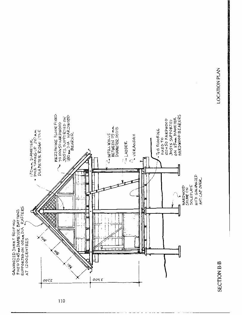
110

APPENDIX 9 Australian Standards The following Australian Standards should be of use to the owner-builder. Up-to-date lists of standards and their prices are available from the Standards Association of Australia, at: 80 Arthur Street, North Sydney, N.S.W. 2060 51 Ring Street, Newcastle, N.S.W. 2300 447 Upper Edward Street, Brisbane, Qld. 4000 AS 1170
AS 1684-1979
AS 1720-1975 AS CC121968
AS 1606-1974
AS 1694-1974
As 1736-1975 AS 1860-1976 AS 1904-1976
AS 20021979
AS 2032-1979 AS 2033- 1979
AS 2057- 1977
AS 2147-1978
AS 2178-1978
As 2180-1978
AS CA39-1963
AS CA55-
AS CA56-
970
968
SAA MHZ-1975
As 021973 As 14451977
SAA Loading Codes. Part 1: Dead and Live Loads, Part 2: Wind Loads. SAA Timber framing Code (Tables of sizes and s ans issucd as Supplements P SAA Timber Engineering Code Adequate electrical installations in single and multiple domestic dwellings Water-repellent treatment of timber, joine y and other timber products Physical barriers used in the protection of buildings against subterranean termites. Roof sarking Installation of particleboard flooring Installation of reflective foil laminate in buildings (bound with AS 1903) Installation of household type solar hot water supply systems Installation of LJWC pipe systems Instailation of polyethylene pipe systems Soil treatment for protection of buildings against subterranean termites installation of timber windows in buildings !bolnd with AS 2146) Treatment of subterranean termite infestation in existing buildings Selection and installation of metal r2a;y;ater goods (bound with AS
Thfhanding of interior wooden
Design and installation of bituminous fabric roofing Construction of vitrified clay pipelines (up to and includin diameter with flexible or rigi 1
12-m
systems) joint
Metric data for building designers
Nomenclature of Australian timbers 76 mm pitch corrugated hot-dipped zinc-coated or aluminium zinc-
AS 1903 1976
AS A98- 1959
AS A99- 1959
AS 1859-1976 AS 2269- 1979 AS 2270- 1979
AS 2271- 1
AS 2272- AS 2324- AS 0114- AS 0116- AS 1540-
AS 1641
AS 1702
979
979 979 968 968 974
AS 1706 to 1709-1974 AS 1728-1975 AS 1782 to 1787-1975
AS 1810-1975 AS 091 to 094-1964 AS 1328-1972 AS 14891973 AS 070-I 958
AS 1218-1972 AS 1229-1972 AS 1546-1976 AS 1589-1979
AS X46-1977
AS i718-1975
AS 17301975
coated steel sheet in coil and c~,t lengths Reflective foil laminate (bound with AS 1904) Bituminous felt roofin Ty e 1 (a) - Saturated organic bre elt t? P roofing Bituminous felt roofing. Type 1 (c) - Coated organic fibre felt roofing Fiat pressed particleboard Structural plywood Plywood and blockboard for interior use Plywood and blockboard for exterior use Marine plywood PVC film and sheeting Hardboard Organic fibre and insulating board Timber frames and sashes for windows Milled products from Australian rainforest timber Milled products from south-eastern Australian hardwoods Milled products from north-eastern Australian eucalypt hardwoods Types of timber surfaces Milled products from Australian
? rown conifers (softwoods) excluding radiata pine and cypress
pine) Flooring milled from cypress pine Unseasoned cypress pine sawn boards and milled products Glued-laminated structural timber Sawn boards from radiata pine Sawn house stumps, sole plates, fence posts and struts from south- eastern Australia hardwoods Flushing cisterns Laund y troughs Small septic tanks Copper and copper based allo fittin
s s for use in sanitary plum g ing
insta lations Rubber joint rings for water supply, sewerage and drainage purposes Copper alloy draw-off taps, stop taps and ferrule or main taps for use in water supply and hot water services Washbasins
111
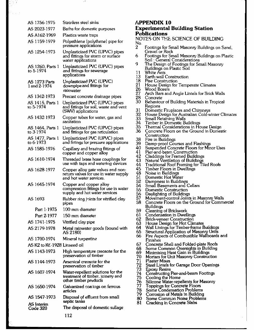
AS 1756-1975 AS 2023-1977 AS A162-1969 AS 1159-1979
AS 1254-1973
AS 1260, Parts to 5-1974
AS 1273 Parts 1 and 2-1974
AS 1342-1973 AS 1415, Parts 1 to 5-1974
AS 1432-1973
AS 1464, Parts 1 to 3- 1974 AS 1477, Parts 1 to 6-1973 AS 1585-1976
AS 1610-1974
AS 1628-1977
AS 1645-1974
AS 1693
Part 1-1975 Part 2-1977
AS 1741-1975 AS 2179-1978
AS 1700-1974
Stainless steel sinks Baths for domestic purposes Plastics waste traps Polyethlene (polythene) pipe for pressure applications Un an s
lasticized PVC (UPVC) pipes fittings for storm or surface
water applications Un an x
lasticized PVC (UPVC) pipes fittings for sewerage
applications Unplasticizec! PVC (UPVC) downpipe and fittings for rainwater Precast concrete drainage pipes Un
x lasticized PVC (UPVC) pipes
an fittings for soil, waste and vent (SWV) applications Copper tubes for water, gas and sanitation Un lasticized PVC (UPVC) pipes an dp fittings for gas reticulation Un lasticized PVC (UPVC) pipes an x fittings for pressure applications Capillary and brazing fittings of copper and copper alloy Threaded brass hose couplings for use with taps and watering devices Copper alloy gate valves and non- return valves for use in water supply and hot water services. Copper and copper alloy compression fittings for use in water supply and hot water services Rubber ring joints for vitrified clay pipes 100 mm diameter 150 mm diameter Vitrified clay pipe Metal rainwater goods (bound with AS 2180) Mineral turpentine
AS K2 to Kc-1928 Linseed oil AS 1143-1973 High temperature creosote for the
preservation of timber AS 1144-1973 Arsenical creosote for the
preservation of timber AS 1607-1974 Water-repellent solutions for the
treatment of timber, joiney and other timber prcpducts
AS 1650-1974 F;paized coa:ings on ferrous
As 1547-1973 Disposal of effluent from small septic tanks The disposal of domestic sullage
APPENDIX 10 Experimental Building Station Publications NOTES ON THE SCIENCE OF BUILDlNG
Footings for Small Masonry Buildings on Sand, Gravel or Rock Footin Soil : 2
s for Small Masony Buildings on Plastic eneral Considerations
The Design of Footings for Small Masonry Buildings on Plastic Soil White Ants Earth-wall Construction Pise Construction House Desisn for Temperate Climates Wood Bore; Arch Bars and Angle Lintels for Brick Walls Concrete Behaviour of Building Materials in Tropical Regions Domestic Firsplaces and Chirnne s House Design for Australian Co1 cr -winter Climates Small Retaining Walls Timber in Domestic Buildings Thermal Considerations in House Design Concrete Floors on the Ground in Domestic Construction Fire in Buildings Damp-proof Courses and Flashin s Suspended Concrete Floors for rf inor Uses Pier-and-beam Construction Claddings for Framed Buildings Natural Ventilation of Buildin s Traditional Roof Framing for I- iled Roofs Timber Floors in Dwellings Noise in Buildin s Domestic Hot d ater Dam ness in Buildinqs Sma 1 Basements and Cellars P Domestic Construction Daylighting of Buildings Movement-control Joints in Masonry Walls Concrete Floors on the Ground for Commercial Buildings Cleaning of Brickwork Condensation in Dwellings Brick-veneer Construction House Design for Hot Climates Wall Linings for Timber-frame Buildings Structural Application of Mason Units Fire Aspects of Combustible Wal boards and r Finish& Concrete Shell and Folded-plate Roofs Some Common Oversights in Building Minimising Heat Gain in Buildings Mortars for Unit Masony Construction Plaster Mixes Steel Lintels for Garage Door Openings Epoxy Resins Canstructing Pier-and-beam Footings Cooling the Home Silicone Water-repellents- for Masonry Toppin s for Concrete Floors Some t? ondensation Problems Corrosion of Metals in Building Some Comma Noise Problems Cracking in Concrete Slabs
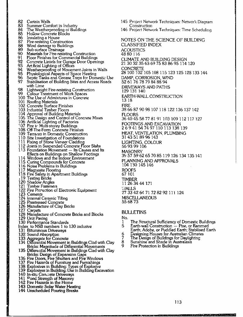
82 Curtain Walls 83 Summer Comfort in Industry 84 The Weatherproofing of Buildings 85 Holiow Concrete Blocks 86 Insulating a House 87 Fire-resisting Construction 88 Wind damage to Buiidings 89 Sub-surface Drainage 90 Materials for Fire-resisting Construction 91 92
FIoor Finishes for Commercial Buildings
93 Concrete Lintels for Garage Door Openings
94 Artficial Lighting of OffIces Weatherproofing of Movement Joints in Walls
95 96
Physiological Aspects of S Septic Tanks and Grease -F
ace Heating raps for Domestic Use
97 Stabilisation of Building Sites and Access Roads with Lime
98 Lightweight Fire-resisting Construction 99 Colour Treatment of Work Spaces 100 The Use of Admixtures in Concrete 101 Roofing Materials 102 Concrete Surface Finishes 103 Industrial Timber Floors 104 A proval of Building Materials 105# D e esign and Control of Concrete Mixes 106 Artificial Lighting of Factories T 07 Fire ii: Multi-storey Buildings 108 Off-The-Form Concrete Finishes 109 Terrazo in Domestic Construction 110 Site Investigation of Foundations 111 Fiing of Stone Veneer Claddin 112 Joints in Suspended Concrete l3 oor Slabs 113 Foundation Movement - Its Causes and Its
Effects on Buildin 114 Windows and the 9
s on Shallow Footings ndoor Environment
115 Curin 116 Noise
Compounds for Concrete %r oblems in Buildings
117 Magnesite Flooring 118 Fire Safety in Apartment Buildings 119 Testing Bricks 120 Shadow Angles 121 Timber Fasteners 122 Fire Protection of Electronic Equipment 123 Cements 124 Internal Ceramic Tiling 125 Prestressed Concrete 126 Manufacture of Clay Bricks 127 Carpets 128 Manufacture of Concrete Bricks and Blocks 129 Unit Paving 130 Performance Standards Index to NSB numbers 1 to 130 inclusive 13 1 Bituminous Drivewavs 132 Sound Absorption z 133 Ag 134
egate for Concrete Di .erential Movement in Buildin P Bricks: Maonitude of Differential
s Clad with Clay %l ovements
135 DifferentiarMovement in Buildings Clad with Clay Bricks: Desi
136 Fire Doors, P of Expansion Gaps
ire Shutters and Fire Windows 137 Fire Hazards of Furniture and Furnishings 138 Explosives in Building: Types of Explosive 139 Explosives in Building: Use in Building Excavation 140 In-situ ConL;ete Driveways 141 Pond Strength of Masonry 142 Fire Hazards in the Home 143 Domestic Solar Water Heating 144 Unscheduled Pouring Breaks
145 Project Network Techniques: Networ!< Diagram Construction
146 Project Network Techniques: Time Scheduling
NOTES ON THE SCIENCE OF BUILDING CLASSIFIED INDEX ~~~~~$C3
CLIMATE AND BUlLDlNG DESIGN 21303235636975838695114120 CONCRETE 28100102105108115123125128133144 DAMP, CORROSION, WIND 5261767879848894 DRIVEWAYS AND PATHS 129 131 140 E;H-WALL CONSTRUCTlON
FlRE 3866879098107118122136137142 FLOORS 36404558778191103109112117127 FOOTINGS AND EXCAVATION 26941547497110113138139 HEAT, VENTILATION, PLUMBING 3143518996143 LIGHTING, COLOUR 569399 106 MASONRY 39575962657085119126134135141 PLANNING AND APPROVALS 104130145146 ROOFS 67 101 TIMBER 11263444121 !v’]pJJfi
2733426471728292 ~;;$jL3LANEOUS
111 124
BULLETINS No. 1 5
The Structural SufFiciency of Domestic Buildings Earth-wall Construction - Pise, or Rammed Earth; Adobe, or Puddled Earth; Stabilised Earth
6 Desi 7 The
ning Houses for Australian Climates 9,
8 esign of Buildings for Daylighting
Sunshine and Shade in Australasia 9 Fire Protection in Buildings
113

,,,:,,
.:
TECHNICAL STUDIES No.
iii!
31
E
42
43
E
:: 48
Report on Simulated Wind Pressure Tests Recommended Interim Code of Practice for Concrete Walls, Type IV Foundation Soils in Austrz;ia Climate and Design of Buildings Climate and Design of Buildings - The Thermal Behaviour of Dwellings Pier-and-beam Footings for Single-storey Pcmestic Construction ( ” acking in Brick and Block Masonry Footings on Problem Soils The Use of Admixtures in Concrete Stone Veneer Cladding The Weatherin of City Buildin s Airborne Soun 3 Transmission lx rough Elements of Buildings
SPECIAL REPORTS No. 19 Air Movement in Industrial Buildings - Effects of
Nearby Buildings 20 Gypsum-plaster Wall Panels 22 Circumferential Stresses in a Joint between
Structural Tubes 23 zkz;; Flat-slab Construction under Uniform
24 Small Specimens af Brickwork as Design and Constniction Criteria
These publications are available from the Experimental Building Station, Department of Housing & Construction, P.O. Box 30, Chatswood, 2067.
APPENDIX 11 Submissions Received Submissions were received from the following individuals and or anisations. Most contributions have been incorporate cp int- the handbook and amendments made where appropriate. However, some material was rejected if it was a!readv covered by commonly available reference matetiai, was more appropriate in a tactical building manual, In conflict with Ordinance 7 0, or not very low cost building standards. The editors of the handbook gratefully acknowledge the submissions received and the care and effort that went into their preparation. John Archer, author Roger Bartlett, Department of Environment and Planning ~~n~l~rawford, Department of Environment and
Simon ii lough, homebuilder, Tweed Jack Dal Gmo, architect/homebuilder Richard is ownes, builder, Sydney J. Gooch, Forestry Commission of N.S.W. M. Gormlv. A. Hopkins, D. Pont, homebuilders, Moruya -’ - Peter Hamilton, Homebuilders’ Association Harry Harris, en ineer/homebuilder, Uki David Kanaley, B eparhnent of Environment and Planning Richard le Plastrier, architect, Lovetts Bay J.F. Lyons, Blacktown City Council Margaret Munro-Clark, University of Sydney Peter Middleton. Universitv of Svdnev Dennis McMa&, architeci, Decartm&nt of Environment and Planning Fergus Neilson, Department of Environment and Planning Chris Nash, builder, Stroud John Paynter, Department of Environment and Planning Planning Lester Prowse, elecxician, Mullumbimby Lester Prowse, elecxician, Mullumbimby Ron Short, Bellingen Shire Council Ron Short, Bellingen Shire Council R.D. Snence. Tweed Shire Council R.D. Snence. Tweed Shire Council j&n &tso& homebuilder, Nimbin Stafford Watts, Deparlment of Environment and Planning - Neil Wilson, Department of Environment and Planning Health Commission of N.S.W. Homebuilders’ Association, Rainbow Region Royal Australian Institute of Architects, Housing Committee, Building Regulation and Standards Committee

Local Government Act N.S.W 1919; Public Health Act N.S.W.; Builders’ Licensin Act N.S.W. 1979; Ordinances 44,4 L! ,70 and 71; Draft Appendix 4 to the Queensland Building Act. Commonwealth Department of Housing and ConstructionExperimental Building Station. “Notes on the Science of Building” series. Commonwealth Scientific and Industrial Research Organisation. The importance of Preservation Treatments in Hardwood Utilization, N. Tamblyn. Division of Forest Products Leaflets. Division of Mechanical Engineering Bulletins. Papua and New Guinea Forest Products Research Centre. Manual of Rum1 Wood Preservation; Pole Buildings in Papua and New Guinea. Forestn, Commission of N.S.W., “Technical Public&ions”. Standards Association of Australia, “Australian Standards”. “British Standard Code of Practice for the Structural Use of Masonry.” Timber Develo Guides; Austm ian Ember Handbook, N.K. Wallis; P
ment Association. Technical Timber
Span Tables. Commonwealth Savings Bank, Housing Loans - Acceptable Standards of Construction. The Ross Institute Information Adviscnr Service - Bulletin No. 8, Small Excreta Disposci-Systems. Department of Environment and Planning. “Guidelines for Siting Rural Dwellings in Coastal Areas”. Technical Bulletin No. 11. Uni. N.S.W. Graduate Schoo! of the Built Environment. Earth Construction, An Adviso y Document. The International Development Research Centre, Low Cost Technology Options for Sanitation.
115
REFERENCES Acts and Ordinances:
Bootle, Keith R., 1971. The Commercial Timbers of N.S. W. and Their Use Sydney. Angus and Robertson. Forestry Commission of N.S.W., 1974. Preservation of Natuml Round Fence Posts. W.T.6. Forestry Commission of N.S.W., 1975. The immunisation of 7imber against attack by Powder Post Beetle (lyctus brunneus) with Bomtes. R.S. Johnstone. WI- 14. Hall, Norman, R.D. Johnston and G.M. Chip endale. 1970. Forest Trees of Austmlia, 3rd edition. e anberra, AGPS. (Now out of print) Holliday, Ivan, and Ron Hill. 1974. A Field Guide to Austmlian Trees. Revised edition. Adelaide, Rigby. Keam & Magars, 1978. Fireplaces. Oakhurst, Calif., Owner Builder Publications. Vivian, John, 1976. Building Stone Walls. Charlotte, Ver., Garden’ Way Publications. Wrigley, John W., 1979. Austmlian Native Plants: A Manual for their Pmpa ation, Cultivation and Use in Landscaping. Sydney, 8 ollins.
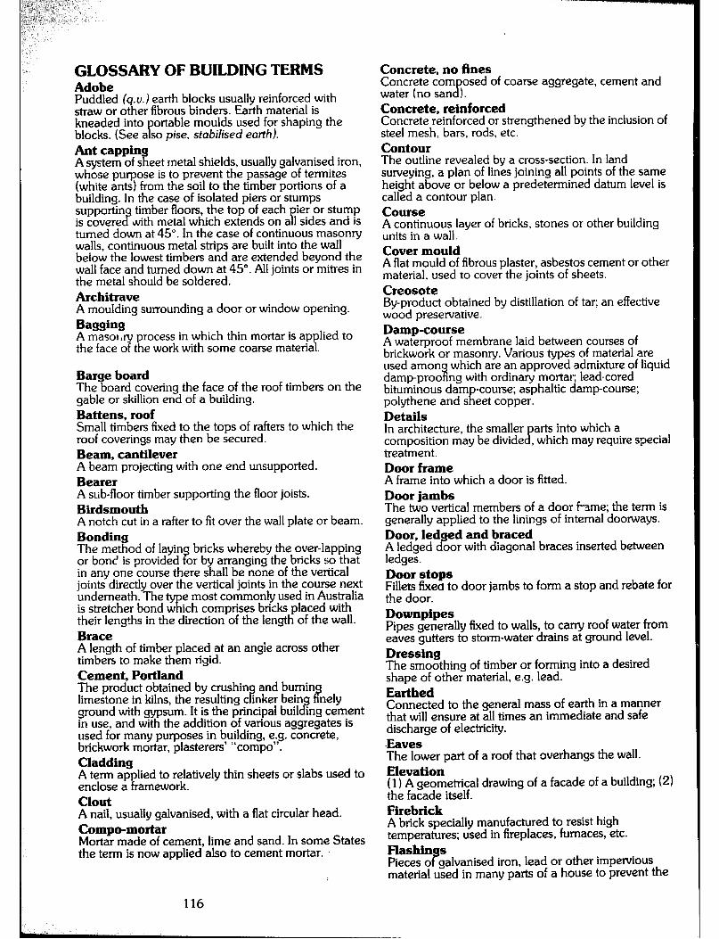
GLOSSARY OF BUILDING TERMS Adobe Puddled (q.o.1 earth blocks usually reinforced with straw or other fibrous binders. Earth material is kneaded into
P ortable moulds used for shaping the
blocks. (See a so pise, stabilised earth). Ant capping A system of sheet metal shields, usually gaivanised iron, whose purpose is to prevent the passage of termites (white ants) from the soil to the timber portions of a building. In the case of isolated piers ar stumps supportin timber floors, the top of each pier or stump is covere c? with metal which extends on all sides and is turned down at 45”. In the case of continuous masonry walls, continuous metal strips are built into the wall below the lowest timbers and are extended beyond the wall face and turned down at 45”. All joints or mitres in the metal should be soldered. Architrave A moulding surrounding a door or window opening. BwMw A masor,y process in which thin mortar is applied to the face of the work with some coarse material.
Barge board The board covering the face of the roof timbers on the gable or skiilion end of a building. Battens, roof Small timbers fixed to the tops of rafters to which the roof coverings may then be secured. Beam, cantilever A beam projecting with one end unsupported. Bearer A sub-floor timber supporting the floor joists. Birdsmouth A notch cut in a rafter to fit over the wall plate or beam. Bonding The method of layin bricks whereby the over-lapping or bone is provided or by arranging the bricks so that s in any one course there shall be none of the vertical joints directly over the vertical joints in the course next underneath. The
@R e most commonly used in Australia
is stretcher bond w ich comprises bricks placed with their lengtts in the direction of the length of the wall. Brace A length of timber placed at an angie across other timbers to make them rigid. Cement, Portland The product obtained by crushin limestone in kilns, the resulting c inker being P
and bumin IT nely
ground with gypsum. It is the principal building cement in use, and with the addition of various aggregates is used for many purposes in building, e.g. concrete, brickwork mortar, plasterers’ “compo”. Cladding A term applied to relatively thin sheets or slabs used to enclose a framework. Clout A nail, usually galvanised, with a flat circular head. Compo-mortar Mortar made of cement, lime and sand. In some States the term is now applied also to cement mortar.
116
Concrete, no fines Concrete corn osed of coarse aggregate, cement and water (no san B ). Concrete, reinforced Concrete reinforced or strengthened by the inclusion of steel mesh, bars, rods, etc. Contour The outline revealed by a cross-section. In land surveying, a plan of lines joining all points of the same height above or below a predetermined datum level is called a contour plan. Course A continuous layer of bricks, stones or other building units in a wall. Cover mould A flat mould of fibrous plaster, asbestos cement or other material, used to cover the joints of sheets. Creosote By-product obtained by distillation of tar; an effective wood preservative. Damp-course A waterproof membrane laid between courses of brickwork or masonry. Various types of material are used amon which are an approved admixture of liquid damp-pro0 1 ng with ordinary mortar; lead-cored bituminous dam polythene and s R
-course; asphaltic damp-course; eet copper.
Details In architecture, the smaller composition may be divide s
arts into which a , which may require special
treatment. Door frame A frame into which a door is fitted. Door jambs The two vertical members of a door fame; the term is generally applied to the linings of internal doorways. Door, ledged and braced A ledged door with diagonal braces inserted between ledges. Door stops Fillets fixes to door jambs to form a stop and rebate for the door. Downpipes Pipes generally fixed to walls, to carry roof water from eaves gutters to storm-water drains at ground level. Dressing The smoothing of timber or forming into a desired shape of other material, e.g. lead. Earthed Connected to the general mass of earth in a manner that will ensure at all times an immediate and safe discharge of electricity. -Eaves The lower part of a roof that overhangs the wall. Elevation ( 1) A geometrical drawing of a facade of a building; (2) the facade itself. Firebrick A brick specially manufactured to resist high temperatures; used in fireplaces, furnaces, etc. Flashin s Pieces o P galvanised iron, lead or other impervious material used in many parts of a house to prevent the

penetration of moisture. Flashing, stepped Shaped pieces of material used for flashings where a sloping roof abuts a wall or chimney. Each piece of material is inserted into the wall joints and dressed over the roofing material. Footing The construction whereby the weight of the structure is transferred frqm the base structure to the foundation (q.u.). Fomwork Prepared forms of timber or other material for the casting of concrete work. Foundation Tile ground upon which the footings of a building are constructed. Frame (1) In joiney, the name given to the frame around a dcor or window opening; (2) in carpentry, the main timbers of a structure when fitted and joined together. Gable The triangular end of a house formed at the end of a pitched roof, from eaves line to apex. Glazing, bead Small moulding for holding glass in place. Grout Mortar made thin by the addition of water so that it will run into open joints, for the purpose of ensuring the structural solidity of brickwork. Halving A joint made by cutting the op osite halves of the thicknesses out of two pieces o P timber, to the full width of the timber. Head The upper horizontal member of c’ door or window frame, or the top of an opening. Health The floor of a fireplace, including a small area in front of the fireplace specially paved with incombustible materials. Hei The ifi
ht, ceiling
ceilin eight of a room measured from floor surface to
the ra or, where there is no ceiling, to the underside of
9t ers. HP A slanting ridge formed by the intersection of two sloping roof surfaces. Hip roof A roof roughly pyramidal in shape, with surfaces sloping upwards from all the eaves. House (v.) To recess the end of one piece of timber into another without reducing the thickness of the former piece. Inspection opening (Plumbing); an openin
f? , sealed with a removable disc,
provided in a pipe or tiing for inspection or cleaning purposes. Jambs Side surfaces of an opening in a wall. (See also reoeafl. Jamb linings Linings of internal door or window openings.
Joists, ceiling Timber members spanning wails or other supports, to which the ceiling is attached. Joists, floor Timber members to which the flooring is fixed. Lap, end In roofing, tJe amount b of roofing overlaps the s z
which the upper sheet or unit eet or unit immediately below
it. Lap, side In roofing, the amount by which sheets or units of roofing materials cverlap each other at the side joints. In plain sheeting, tiles, etc. the side lap is s;tat;.i;mm, bl,t in corrugated sheeting it is general1 ccmrgations, e.g. half, one, one and a rl a f, etc. Linear (running) A measurement of length. Lintel A horizontal load-bearing member spanning an opening. Load, dead The actual weight of all permanent structural and finishing work in a building, including partition walls. Load, live All load other than dead load, including wind load (q.0.) and designed floor and roof loadings. Load, wind Loading on a roof, wall, etc., due to wind pressure only. Mortar A composition of lime and/or cement and sand mixed with water in variou’s proportions. Mullion A vertical member dividing a window frame. Nails, roofing A alvanised nail with a mushroom-shaped head used to \ x corrugated iron sheets. Noggin A horizontal piece of timber fixed between studs in a framed wall. Orientation The siting of a house in relation to prevailing weather, air movement, sun exposure and outlook. Palings Pieces of rough sawn or split timber, usually about 1 cm thick, used for sheeting, fencing, etc. Parsing The mortar coating of the internal surfaces of a chimney flue. Perpends The vertical joints in a masonry wall. Pier A column or post su porting a superstructure such as floor bearers, veran 8 ahs, beams, etc. Pier, engaged A pier bonded into a wall. Pier, sleeper Independent brick, concrete or wooden supports for floors bearers. (See also stump). Pise Prepared earth rammed between formwork similar to that used for poured concrete walis. This provides monolithic walling. See also adobe and stabilised earth.
117
Pitch The angle of inclination to the horizontal of a roof or stair. Plate, floor In brick construction, a timber member continuously supported on brickwork and used to carry floor joists. Plate, sole A piece of timber or other material placed on or in the ground to distribute the weight of a vertical load- bearing member. Plates, wall In brick construction, timber members placed on brick or other supports to carry the floor joists, and on tops of walls to carry ceiling joists and rafters; in timber framing there are top and bottom plates, which are the top and bottom members of the framed walls. Plug A small piece of timber driven into the joints of brickwork or into concrete to form a fixing point for finishing timbers. Many types of metal plugs are also in use in connection with other types of fitting. Plumb (adj.) Vertical or perpendicular. Ply One layer of *a laminated sheet. Pointing In bricklaying, the recess of filling mortar joints after the construction o P the wall. Puddle (v.) To consolidate earth by adding water and ramming. Purliis In simoie roof construction, longitudinal roof timbers giving-intermediate support for rafters, supported at intervals longitudinally by struts. Rafter, commopl In roof construction, a timber framing member providing the principal support for the roofing material. itail A piece of timber or metal extending from one post to another, as in fences, balustrades, staircases, etc.; in joiney, framing. Ram To compact or consolidate, e.g. the consolidation of earth around fence posts, foundations, etc. See also puddle. Rebate (rabbet) A step-shaped reduction cut along an edge or face or projecting angle of wood, etc. Rendering, cement The covering of a wall surface with one or more coats of cement mortar. Reveal The thickness of wall from the wall face to the door or window frame. The remainder of the thickness of wall is known as the jamb. Ridge The highest part of the roof of a building at the meeting of the upper end of the common rafters. Roof, lean-to See skillion.
Sarking A covering of water-proof building paper or boarding fixed on the top of the rafters, beneath the external roof covering. Scarfmg The joinin
it of two pieces of timber together in length
zhzpch t e two ends are cut to lap o;rer and fit each
Screed (n.) A narrow band of timber or other material applied to a surface as a guide to indicate the correct height or level of the finished work. Screed (v.) To bring materials to a true surface by means of a straight edge, using the screeds as a guide. Section A drawing showin interior details of a structure, presupposing the ii? uilding is cut through vertically, so as to exhibit the walls, the heights of ceilin s, internal doors and other apertures, the thickness o 9 floors, etc. Septic tank Tank used to dispose of sewage when a building is isolated from or cannot be connected to a sewerage system, the sewage being li bacteria. The excess or ove 41
uefied and purified by
the effluent. owing liquid is known as
Sill The horizontal member at the bottom of a door or window frame, etc. Skillion or lean-to roof A roof sloping in one direction only with the rafters pitching or leaning against a wall. Square Term used to indicate that the surfaces of two faces are at right angles. Stabilised earth Pre >ared earth, to which is added a stabilising agent sue k as Portland cement or bituminous cold emulsion. Used either in “rammed in situ” or in block construction. See also adobe and pise. Stile The outer vertical member of a framing or panelling, door or window. Strap A metal strap such as is used to support a ceiling joist from a hanging beam. Stretcher A brick laid with its length along the wall. See bonding. Studs or studding The vertical members in the wall framework of a timber building. Stump (pier) A vertical member of timber or precast concrete sunk into the ground and used to support a floor or wall framework. Sullage The waste liquids discharged from all plumbing fktures excluding water closets and urinals. See tank, septic.
Termite shield See ant cupping. Threshold The step or sill of an external door.
118
\
\ Tie A horizontal member in tension, usually a timber or steel rod binding two members or sections of a building together to prevent spreading. See tie, collar. Tie, collar A timber member tying a pair of rafters;, usual1 midway between the wall plate and ridge (q.u. Y
placed .
Ties, wall Suitably shaped galvanised wire or galvanised iron straps built into cavity walls to bind the inner and outer leaves; also used in brick veneer construction to bind timbers to the brickwork. Tongue and groove A method by which one board is grooved along the edge and the other tongued, so that one fits into the other. Trap, grease A trap designed to prevent grease from entering the drainage system. Trim (v.) To construct a fmmed opening in any part of a timber framework. Trimmer The timber cross-member inserted when an opening is formed in framework to which the ends of the cut members are fixed. The trimmer itself is fixed between uncut members. Weatherboards External wall sheeting formed with overlapping or rebated boards. Weathering The sloping surface, e.g. of a sill coping, designed to permit rapid shedding of water. Weep holes Openings left in perpendicular joints of a brickwork course over flashings and at the bottom of cavities for drainage purposes.
119