Embed Size (px)
Citation preview
A Primer for
Model-Based Systems Engineering
2nd Edition
David Long and
Zane Scott

Copyright © 2011 Vitech Corporation. All rights reserved.
ISBN 978-1-105-58810-5 (paperback edition)
Permission to reproduce and use this document or parts thereof and to prepare derivative works from this document is granted, provided that both attribution to Vitech Corporation and this copyright notice are included with all reproductions and derivative works.
Product names mentioned herein are used for identification purposes only, and may be trademarks of their respective companies.
Publication Date: October 2011

DEDICATION
We dedicate this edition of the Vitech MBSE Primer to the
memory of our friend and mentor, Jim Long. He blazed the
trail in this discipline from his days as a TRW engineer to his
years as our Chief Methodologist. His stories of his many
experiences along the way formed a light bright enough to
illuminate the path forward for us and the many others whose
lives he touched. He always encouraged us to be more than
we thought possible. In a letter to Robert Hooke, Isaac
Newton wrote, “If I have seen further it is only by standing on
the shoulders of giants.” Jim is surely the giant on whose
shoulders we have stood to see the way forward. This is for
him.
Vitech Corporation Research and Education Council

THIS PAGE INTENTIONALLY BLANK
CONTENTS
INTRODUCTION .................................................................................. i
THE PROBLEM: A GEOSPATIAL LIBRARY .............................................. v
WHAT IS A SYSTEM? .......................................................................... 1
SYSTEMS THINKING .................................................................................... 4
APPLYING SYSTEMS THINKING TO SYSTEMS DESIGN ......................................... 7
WHAT IS SYSTEMS ENGINEERING? ................................................... 11
MULTIDISCIPLINARY APPROACH ................................................................. 13
PROBLEM CLASSES ................................................................................... 13
THE DESIGN SPACE: THREE SYSTEMS ........................................................... 16
THE DESIGN SPACE: BOUNDARIES............................................................... 20
THE PROCESS .......................................................................................... 21
DOMAINS ............................................................................................... 24
COMMUNICATION .................................................................................... 29
WHAT IS A MODEL? ......................................................................... 31
FOUR ELEMENTS OF A MODEL ................................................................... 32
CHARACTERISTICS OF A MODEL .................................................................. 33
LANGUAGE: THE SYSTEMS MODEL IS LANGUAGE-BASED ................................ 34
LANGUAGE OF BEHAVIOR .......................................................................... 39
MANAGING COMPLEXITY WITH LANGUAGE .................................................. 42
STRUCTURE: THE MODEL EXPRESSES SYSTEM RELATIONSHIPS ......................... 44
ARGUMENT: THE MODEL IS USED TO “PROVE” THE CONCEPT OF THE DESIGN ... 53
PRESENTATION: THE MODEL MUST BE “VIEWABLE” ..................................... 54
WHAT IS MODEL-BASED SYSTEMS ENGINEERING? ............................ 65
REQUIREMENTS FOR A SYSTEMS ENGINEERING PROCESS ................................ 68
MBSE MODEL AND SYSTEM DEFINITION LANGUAGE ..................................... 74
DEVELOPING LAYER 1 OF OUR SOLUTION..................................................... 76
PROCEEDING WITH LAYER 2 ....................................................................... 85
ARCHITECTURE DESIGN AT LAYER N ............................................................ 95
VERIFICATION AND VALIDATION ................................................................. 97
SUMMARY .................................................................................... 103
AFTERWORD ................................................................................. 105
AUTHORS ...................................................................................... 107

THIS PAGE INTENTIONALLY BLANK
A Primer for Model-Based Systems Engineering
i
INTRODUCTION
This is the 2nd edition of Vitech’s model-based systems
engineering primer. In this second treatment of the subject,
we have covered the same subject matter as before but
augmented this time with what we have learned since
releasing the 1st edition. We strive to be a “learning
organization” and to leverage that learning for the benefit of
our customers and community. With this edition we hope to
carry that principle forward.
There are notable differences in this edition. First, we have
reorganized the material. Instead of the topical organization of
the 1st edition, we have approached the description of model-
based systems engineering (MBSE) from a “building blocks”
perspective suggested by its name. We ask first “What Is a
System?” From there we tackle “What Is Systems
Engineering?” Then we discuss “What Is a Model?” and finally
arrive at the question “What Is Model-Based Systems
Engineering?” We hope that this building approach will make
it easier to put the concepts into a logical framework for
understanding and use.
We have also tied the concept discussions more closely to
practical illustrations. We have largely drawn these from the
example system design included with this primer. This has
been done in response to many helpful suggestions from our
readers, and we think it makes the concepts much clearer and
easily understood.
One of the most common flaws in any undertaking is a
departure from the fundamental principles of the disciplines
involved in the process. This can be due to inattention bred by
familiarity or a failure to recognize and reinforce “the basics.”
Whether the enterprise is a football game or a systems design
A Primer for Model-Based Systems Engineering
ii
project, the fundamentals of “blocking and tackling” are
critical to success. Absent or poorly executed, they can doom
the venture. In the case of a floundering effort, they are the
key to getting back on track.
The importance of knowing and executing the basics is the
driving force behind this primer. It is the reason for not
beginning with a collection of essays on more advanced topics.
Revisiting the “blocking and tackling” aspects of MBSE is the
foundation of our effort to advance the cause of sound
systems design.
This primer addresses the basic concepts of model-based
systems engineering. It covers the Model, Language, Behavior,
Process, Architecture, and Verification and Validation. It is a
call to consider the foundational principles behind those
concepts. It is not designed to present novel insights into
MBSE so much as to provide a guided tour of the touchstones
of systems design. It is a guide to the new MBSE acolyte and a
reminder to the experienced practitioner.
Why such a basic approach? Without this grounding, it can
become easy to lose the sense of relationship between
techniques and the design itself. Reading and pondering the
sections on Models and Language bring into focus the
difference between representations of the model and the
model itself. A map may be an extensive, informative, and
important representation of the underlying terrain, but it is
simply that—a representation. Likewise, a set of diagrams may
be useful, clear, and detailed, but they are not the model of
the system itself. Without returning to the concepts of model,
language, process, and behavior, we can easily become
mistakenly convinced that the process of drafting a “full set”
of representations is the same thing as constructing a model.
It is through understanding the basics that we understand the
distinctions.
A Primer for Model-Based Systems Engineering
iii
In other ways as well, the failure to be aware and alert to the
basic principles of MBSE can hinder the integrity of a system-
design effort. Just as a football team returns again and again
to their roots in basic skills, we can all profit from
reacquainting ourselves with these basic principles.
This primer is offered to the end that it will function as a call
back to the basic concepts of our discipline. It lays the
groundwork for improvements and enhancements already
being planned. As it stands, it is a look at the foundational
concepts of MBSE designed to benefit the newcomer and
experienced practitioner alike.
Finally, for whom is this primer intended? Of course the
obvious answer is that it is intended to be an introduction to
these concepts for those who may be new to the world of
model-based systems engineering. It is written in a way that
can be understood by any intelligent and curious reader—
even if that reader is not an engineer. Project managers,
acquisitions professionals, and business-process consultants
can all use this primer to guide them into the MBSE concepts
in an organized way.
In addition, this primer is intended to provide an organized
presentation of these concepts for the systems engineering
practitioner who may need a reference framework for them.
Often we become familiar with the concepts we use in the
way that we customarily use them. This is as true in the
systems engineering discipline as in any other. Like a gradually
fragmenting hard drive, our thinking becomes
compartmentalized in ways that reflect how much and when
we use the concepts we have learned over time.
With this primer we hope to provide the seasoned practitioner
a framework in which to refresh the concepts and see the
relationships. Any experienced systems engineer can take

A Primer for Model-Based Systems Engineering
iv
these and expand them with additional detail and application
anecdotes. It is our hope that this basic discussion can provide
a “rack” in which to place that experience and, thereby, make
it more useful in practice.
It is our hope that you find this primer valuable. We welcome
your comments and suggestions about improving it. Much of
what we have learned about how it should be organized and
presented has come from thoughtful contributions from the
readers of the 1st edition.
Vitech Corporation
October 2011
A Primer for Model-Based Systems Engineering
v
THE PROBLEM: A GEOSPATIAL
LIBRARY
Throughout this primer, we will consider examples drawn
from the following sample system design problem. In accord
with our ultimate destination, a layered approach to model-
based systems engineering (MBSE), we will begin our
description of the system at a very high level.
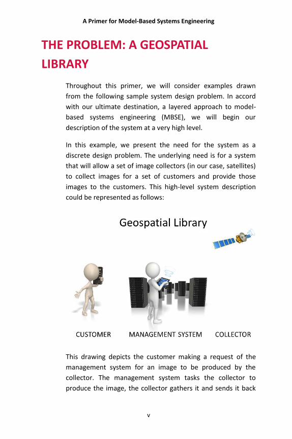
In this example, we present the need for the system as a
discrete design problem. The underlying need is for a system
that will allow a set of image collectors (in our case, satellites)
to collect images for a set of customers and provide those
images to the customers. This high-level system description
could be represented as follows:
This drawing depicts the customer making a request of the
management system for an image to be produced by the
collector. The management system tasks the collector to
produce the image, the collector gathers it and sends it back
A Primer for Model-Based Systems Engineering
vi
to the management system, whereupon it is provided back to
the customer. The customer, the management system, and
the collector are all shown separately.
In this problem, the system to be designed is the management
system. It will interface with the customer and the collector,
but the design and function of those systems are outside the
scope of the problem. They simply impose conditions which
their respective interfaces must meet.
It is obvious that the customer in this system must be able to
make a request (place an order) for an image. The collector
network, however, is a sensitive set of government satellites.
The images produced can’t be distributed to just anyone who
decides to request them. A customer qualification process is
needed to certify the eligibility to make requests.
These considerations are initially presented to the design
team in a concept of operations (CONOPS) document. The
system documentation is later expanded to include a source
document which incorporates an engineering standards
document by reference.
As the designers further explore the capability to accept
customer requests, it becomes clear that customers need to
be able to place orders in person, on the phone, by hardcopies
delivered by messengers, by fax, and over the web. The
capability to accommodate all five of these formats elaborates
on the highest level requirement that the system “accept
information requests from certified customers.”
As the system design discussions unfold, it becomes apparent
to the system stakeholders that a great deal of inefficiency will
result if the system is unable to catalogue and store images
that are taken. If another customer wants the same image,
unless there is a searchable image library, the collector(s) will
A Primer for Model-Based Systems Engineering
vii
have to be retasked, and the work associated with gathering
and processing that image will be duplicated. Therefore, the
stakeholder has asked that the design include an image library
capability.
There are also performance and resource limitations to be
considered. The system will have only 25 people per shift to
operate all functions. Performance standards will also include
responding to customer requests within 24 hours. These
standards are set out in the source document as
requirements. In addition, the source document requires that
the system must be available around the clock every day of
the year. Availability is defined as having 10 minutes or less
down time each month.
We will use this system design as a source of examples and
discussions throughout the primer. From it we will illustrate
the basic concepts of model-based systems design.

A Primer for Model-Based Systems Engineering
THIS PAGE INTENTIONALLY BLANK

A Primer for Model-Based Systems Engineering
1
WHAT IS A SYSTEM?
Although the term system is defined in a variety of ways in the
systems engineering community, most definitions are similar
to the one used in the U.S. Department of Defense
Architecture Framework (DoDAF)—“any organized assembly
of resources and procedures united and regulated by
interaction or interdependence to accomplish a set of specific
functions.” (Department of Defense Dictionary of Military and
Associated Terms, its.bldrdoc.gov/fs-1037/dir-036/_5255.htm).
In her book Thinking in Systems: A Primer (Chelsea Green
Publishing, 2008), Donella Meadows puts it somewhat more
succinctly by saying “A system is an interconnected set of
elements that is coherently organized in a way that achieves
something.” She goes on to point out that “A system is more
than the sum of its parts. It may exhibit adaptive, dynamic,
goal-seeking, self-preserving, and sometimes evolutionary
behavior.”
The idea that a system is “more than the sum of its parts” is
picked up in the International Council on Systems Engineering
(INCOSE) definition of a system. INCOSE defines a system as “a
construct or collection of different entities that together
produce results not obtainable by the entities alone” (“A
Consensus of the INCOSE Fellows”, www.incose.org/practice/
fellowsconsensus.aspx).
There are some clear commonalities among these three
definitions. First, any system must be made up of what
Meadows refers to as “elements” (called an “assembly of
resources and procedures” in the DoDAF definition and
“entities” by INCOSE). These are the parts of the system that
together form the whole.
A Primer for Model-Based Systems Engineering
2
In addition, a system must tie the parts together with
relationships. What Meadows calls “interconnect(ion)” and
“coherently organized” is for INCOSE a “construct” and for
DoDAF an “organized assembly . . . united and regulated by
interaction or interdependence.” The concept of relationships
is the second common characteristic of these definitions.
Finally, the system must have a purpose for which the
elements are assembled. DoDAF calls this organizing purpose
“to accomplish a set of specific functions.” INCOSE sees it as
the ability to “produce results not obtainable by the entities
alone.” For Meadows the system is “organized in a way that
achieves something.” In each definition the elements of the
system are related to each other in ways that promote the
accomplishment of a specific purpose that is beyond the
capability of any of the parts acting alone.
It should be noted at this point that these aspects of a system
are often construed narrowly in practice, causing our view of
systems to be constrained or limited. In reality, systems exist
wherever these three are present: parts, relationships, and a
purpose. This primer will be intentionally broad in its view of
where those aspects are present. This will enable us to see
systems in places where heretofore we might not have
expected them.
Some examples of systems include:
A set of things working together as parts of a mechanism
or an interconnecting network.
A set of organs in the body with a common structure or
function.
A group of related hardware units or software programs
or both, especially when dedicated to a single application.
A major range of strata that corresponds to a period in
time, subdivided into series.
A Primer for Model-Based Systems Engineering
3
A group of celestial objects connected by their mutual
attractive forces, especially moving in orbits about a
center.
The entities or elements of a system constructed by humans
can include people, hardware, software, facilities, policies, and
documents. For any given system, this list is limited only by
the set of things required to produce its system-level results.
These results include system-level qualities, properties,
characteristics, functions, behavior, and performance. The
value added by the system as a whole, beyond that
contributed independently by the parts, is primarily created by
the relationships among the parts. In other words, the “value-
add” of the system emerges in the synergy created when the
parts come together.
The sample problem included with this primer is that of a
Geospatial Library tasked with connecting a set of satellite
imaging collectors with its customers. It is composed of parts.
At the highest level, it has a Command Center Subsystem that
manages the collection, storage, and retrieval of imagery
products as well as a Workstation Subsystem that manages
the translation of various incoming imagery requests into an
internal common imagery collection request.
The system parts have relationships that define their
interaction and the system’s function. For example, when a
customer request cannot be serviced from the system’s
current inventory, the Command Center Subsystem makes a
specific collection request to a specific sensor to satisfy the
customer's need. The products generated from this request
are collected, added to the Geospatial Library inventory, and
combined into a package for shipment to the customer by the
Workstation Subsystem. Together, the parts of the system
have allowed the system to take a specific customer request,
A Primer for Model-Based Systems Engineering
4
obtain the images necessary to satisfy that request, and
provide the images to the customer in response.
This fulfills the system’s purpose—servicing the needs of the
customers and collectors in facilitating the exchange of
requests for images and the images themselves. At a very high
level this illustrates the presence of the parts, relationships,
and purpose in the sample system.
Systems Thinking
In order to create systems, it is necessary to engage in
“systems thinking.” Peter Senge’s book The Fifth Discipline
(Doubleday/Currency, 1990) introduced systems thinking into
popular culture. However, it remains largely unappreciated
and is honored mainly in the breach rather than the
observance. Part of this is because systems thinking is
practiced using too narrow a definition of “systems,” and this
narrowness limits the practice of systems thinking.
For a broad understanding of what is meant by “systems
thinking,” we will turn to one of the preeminent systems
thinkers, Russell Ackoff. Notice his use of the three aspects of
the systems definition (parts, relationships, and purpose) in
defining systems thinking: “systems thinking looks at
relationships (rather than unrelated objects), connectedness,
process (rather than structure), the whole (rather than just its
parts), the patterns (rather than the contents) of a system,
and context” (R. Ackoff with H. Addison and A. Carey, Systems
Thinking for Curious Managers, Triarchy Press, 2010).
Ackoff goes on to state, “Thinking systemically also requires
several shifts in perception, which lead in turn to different
ways to teach, and different ways to organize society.” This
statement is significant in two ways. First, Ackoff is observing
A Primer for Model-Based Systems Engineering
5
that the move to systems thinking requires changing the way
we think. In addition, he is showing that he sees systems (and
systems thinking) quite broadly.
Taking his latter suggestion first, Ackoff is interested in the
application of systems thinking beyond the classic boundaries
of systems engineering. Coming from a business and process
orientation (as opposed to an engineering orientation), Ackoff
sees the concepts of systems and systems thinking as broadly
applicable to business and even social process design. In his
book Redesigning Society (R. Ackoff and S. Rovin, Stanford
Business Books, 2003), he focuses on the systems aspects of
public policy decision making. He is truly committed to the
idea of seeing systems wherever the three aspects are
present.
Perhaps his most important insight has to do with the “shifts
in perception” or changes in thinking involved in thinking
systemically. A major shift in thinking comes from moving
away from the exclusively analytic approach that has
characterized our thinking since the Enlightenment. This
analytic approach, according to Ackoff, “is a three-step
process: (1) take the thing or event to be understood apart; (2)
explain the behavior or properties of the parts taken
separately; and (3) aggregate the explanations of the parts
into an understanding of the whole, the thing to be explained”
(Ackoff and Rovin, Redesigning Society). Such “analytic
thinking” takes our focus off of the system and orients it to the
parts individually. This analytic, parts-oriented approach leads
too often to ill-fated attempts to improve system performance
by improving the parts of the system. Not only are such
attempts typically fruitless, but they can actually damage
overall system performance or even destroy the system.
What is needed is a different way of thinking, a way of
approaching problems from a systems perspective. Ackoff calls
A Primer for Model-Based Systems Engineering
6
this new approach “synthetic thinking.” According to Ackoff,
“Synthetic thinking is also a three-step process, each the
opposite of the corresponding step of analysis: (1) identify one
or more systems that contain the system to be explained; (2)
explain the behavior of the containing system (or systems);
and (3) disaggregate the understanding of the containing
system into the role or function of the system to be explained”
(Ackoff and Rovin, Redesigning Society). The critical idea here
is that we begin not from a decomposition of the system into
its parts but from the point of view of the system in its
context.
In the book Systems Thinking for Curious Managers, Ackoff
points out that “Managers should never accept the output of a
technologically-based support system unless they understand
exactly what the system does and why. Many managers who
are unwilling to accept advice or support from subordinates
whose activities they do not fully understand, are nevertheless
willing to accept support from computer-based systems of
whose operations they are completely ignorant. Management
information systems are usually designed by technologists
who understand neither management nor the difference
between data and information. Combine such ignorance with
a management that does not understand the system the
technologists have designed, and one has a recipe for disaster
or, if lucky, large expenditures that bring no return” (Ackoff,
Russell; Addison, Herbert; Carey, Andrew; Gharajedaghi,
Jamshid (2010). Systems Thinking for Curious Managers: With
40 New Management f-Laws).
The point here is that systems must be understood in the
context of what they can do and the world in which they will
do it. It is not enough to see the system as a sum of the
operations of the component functions. It must been seen as a
functioning whole. This is the systems viewpoint.
A Primer for Model-Based Systems Engineering
7
This viewpoint allows us to engage the system without losing
sight of the context and purpose of the system as a whole.
Effective systems thinking combines analytic and synthetic
thinking. It is common to see analytic thinking without its
synthetic sibling. Too often this results in the loss of systems
perspective. At its worst, this becomes component
engineering.
The loss of the systems perspective can be quite costly. When
the consequences of a limited or missing systems view emerge
during the design process—as when different design paths
result in mutually exclusive constraints—the penalty is
expensive rework. Cost and schedule suffer together as the
system is reengineered to correct the problems.
Sometimes the missing perspective doesn’t levy its price until
the system is built. This is the failure that Ackoff calls out—the
failure to “understand exactly what the system does and
why.” This leads easily to unintended consequences as the
system interacts with its environment in unanticipated and
unhelpful ways.
Applying Systems Thinking to Systems Design
A system begins with an idea that must be translated into
reality. The theoretical idea of a system must link to the
engineered system “reality” and vice versa (bidirectional
linkage). The designers must also find a way to clearly show
when and how the theory explains reality and how reality
confirms their theory.
The system design must take into account the system
properties. Within the boundary of a system, there are three
kinds of properties:
A Primer for Model-Based Systems Engineering
8
Entities—These are the parts (things or substances) that make
up a system. These parts may be atoms or molecules; larger
bodies of matter like sand grains, raindrops, plants, or
animals; or even components like motors, planes, missiles,
etc.
Attributes—Attributes are characteristics of the entities that
may be perceived and measured such as quantity, size, color,
volume, temperature, reliability, maintainability, and mass.
Relationships—Relationships are the associations that occur
between entities and attributes. These associations are based
on cause and effect.
In order to explain the design, the engineers must use some
form of expression. When taken together, the properties of
the system—the entities, attributes, and relationships—form a
system “language.” This language is fundamental to being able
to describe and communicate the system among the
engineering team as well as to other stakeholders.
Using this language, the system can be represented
hierarchically, allowing it to be understood as decomposable
into meaningful subunits. These subunits are conventionally
named:
a system is composed of subsystems;
subsystems in turn are composed of assemblies;
assemblies are composed of subassemblies, and
subassemblies are composed of parts.
It is important to note that what may be considered a “part” in
the context of a particular system may be a complete
“system” in its own right. This all depends upon the point from
which the system is viewed and the resulting system boundary
decisions.
A Primer for Model-Based Systems Engineering
9
Often the terms used in describing this hierarchy are not well
specified; some engineers use the term sub-subsystem, others
use the terms component and subcomponent in the hierarchy.
Variant usage only contributes to confusion. In order to avoid
such usage confusion, the term component is used here as an
abstract term representing the physical or logical entity that
performs a specific function or functions.
The parts of a system interact to produce the performance of
the whole system. It is intuitively obvious that all parts of the
system must be functioning as designed in order for the
system to function properly. What is not so obvious is that
improving the function of one of the parts, be that a
subsystem or component or whatever it may be labeled, will
not necessarily improve the functioning of the whole. This is
because of the effects of interaction within the system. For
example, improving the resolution of the images gathered by
the collectors in the sample problem will not improve the
product for the customer if the image inventory cannot
process and deliver them. Any improvement must be
considered from a perspective that looks across the system as
a whole.
The system results at the customer level depend upon the
performance of the entire system. While the components
must be understood from the perspective of whether or not
they can perform the behavior allocated to them by the
system design, it is ultimately the performance of the system
that matters. This must account not only for the capability to
meet the needs of the stakeholders that drove the system
creation but also for any extraneous consequences of system
performance, particularly unintended or unplanned
consequences. Understanding and practicing this is the very
foundation of systems thinking.

A Primer for Model-Based Systems Engineering
THIS PAGE INTENTIONALLY BLANK
A Primer for Model-Based Systems Engineering
11
WHAT IS SYSTEMS ENGINEERING?
According to INCOSE the responsibility of systems engineering
is “creating and executing an interdisciplinary process to
ensure that the customer and stakeholder's needs are
satisfied in a high quality, trustworthy, cost efficient and
schedule compliant manner throughout a system's entire life
cycle” (“A Consensus of the INCOSE Fellows,”
http://incose.org/practice/fellowsconsensus.aspx). Boiled
down to its essence, this means that the systems engineer is
required to create and maintain a system that meets the
customers’ needs. That can be accomplished only when the
focus of the systems engineer is on the whole system and the
system’s external interfaces.
Systems engineering is concerned with the design, building,
and use of systems composed of concrete entities such as
engines, machines, and structures. It is equally concerned with
business systems, which are composed of processes. Engaging
in systems engineering requires an organized means of
thinking about those systems in their operational contexts.
This way of thinking is the heart of systems engineering.
Systems engineering begins by identifying the needs of the
users and the stakeholders to assure that the right problem is
being addressed by the system. The systems engineer crafts
those needs into a definition of the system, identifies the
functions that meet those needs, allocates those functions to
the system entities (components) and finally confirms that the
system performs as designed and satisfies the needs of the
user.
This is both a technical and a management process. The
technical process addresses the analytical, design, and
implementation efforts necessary to transform the
A Primer for Model-Based Systems Engineering
12
operational need into a system of the proper size and
configuration for its purpose. Along the way, it produces the
documentation necessary to implement, operate, and
maintain the system.
The management process supports the technical process by
planning, assessing risks, integrating the various engineering
specialties and design groups, maintaining configuration
control, and continuously auditing the effort to ensure that
cost, schedule, and technical performance objectives are
satisfied. Together, the management and technical processes
create the systems that will meet the customers’ needs.
To be effective in all these areas, systems engineering must,
therefore, provide an organized, repeatable, iterative, and
convergent approach to developing complex systems. The
approach must be “organized,” because without an organized
approach the details of the system under development will be
overlooked, confused, and misunderstood. The approach must
be “repeatable” so that it will apply to other system
development efforts in a way that creates reasonable
assurances of success. It should be both iterative and
convergent, which means the engineering processes repeat at
each level of system design and ensure the convergence of the
development process to a solution.
The success of the development process rests on the ability of
the systems engineer to maintain a system focus. We talked
about systems thinking in the discussion of the essential
characteristics of a system. The systems engineer must keep
the vision of the entire system in mind while moving through
the process of designing the system that will form the solution
to meet the needs of the stakeholders. Losing this focus will
cause the design to fail to meet those needs in one or perhaps
many ways.
A Primer for Model-Based Systems Engineering
13
Multidisciplinary Approach
The discipline of systems engineering brings together
branches of engineering and science in planning and
developing solutions for the stakeholders’ needs. By adopting
a systems view of the problem and the possible solutions,
systems engineers can draw on the different disciplines to
design a solution that most effectively meets the needs of the
stakeholders. The power of systems engineering comes from
using this multidisciplinary approach to problem solving to
satisfy the needs of stakeholders through creating or
improving a system.
Every approach has its advantages and problems. While the
multidisciplinary nature of the systems engineering team
leverages the differing experience and expertise of the various
disciplines, it also creates potential problems resulting from
the variety of specialized vocabulary and ways of
communicating that are customary in those disciplines. It is
the job of the systems engineer to provide the coordination
and communication that will allow the power of a
multidisciplinary approach to benefit the problem-solving
effort without being impeded by the potential
miscommunication and friction between the disciplines.
Problem Classes
Systems engineering can be applied to three classes of
problems: top-down or “clean-sheet” problems, middle-out or
system-improvement problems, and reverse-engineering or
system-replacement problems. The classic problems are the
top-down designs. Often the other two problem classes are
not even considered in discussions of systems engineering.
A Primer for Model-Based Systems Engineering
14
However, all three are significant and can benefit from the
discipline and rigor of systems engineering.
Top-down engineering problems are the best known among
the three problem classes. In these situations the engineering
team is faced with designing an unprecedented system
solution to stakeholder problems. These designs are also
commonly called “greenfield” or “clean-sheet” development
efforts. Such systems have many unknowns. Solving these
unknowns often involves doing research, developing new
materials, new components, and new manufacturing methods
to provide all that is necessary to implement the solution.
The initial definition of a top-down problem is usually to be
found in a document or set of documents setting out the high-
level requirements for the system. The design process begins
with an analysis of these requirements. From this analysis
emerges a high-level description of the system which is then
used in designing the solution system.
Experience is now suggesting that the top-down problems that
have heretofore held center stage are becoming more the
exception than the rule. This is due to the increasing
complexity of our world of interconnected systems and
technology. It is becoming rare that stakeholders truly have
the freedom to design a system in isolation, creating a
completely new solution. Most often the new solution must
incorporate or interface with existing technology/systems, and
these legacy components or interfaces must be accounted for
in the new design. Confronting this problem class is known as
“middle-out” engineering.
Middle-out engineering begins with modeling the “as is” state
of all or a portion of a system. This provides an understanding
of the existing “solution” and the supporting processes and
technology. From there the engineer can begin to see what
A Primer for Model-Based Systems Engineering
15
can and cannot be changed and where the opportunities for
improvement or for meeting new requirements lie. This is the
platform for designing an improved or “to be” set of solutions
to customer-identified problems using the derived system-
level requirements and the customer-developed problem
statement(s).
This approach has been quite successful in process
improvement and system-of-system settings. It is becoming
clear that this problem class will be more and more the
subject of system design needs. Systems engineers will need
to become comfortable working in this arena in order to meet
the needs of their customers.
Bottom-up or reverse engineering applies to upgrading or
replacing legacy systems. Legacy systems may have been in
operation for many years. They may have had extensive
enhancements and fixes added over the life of the system.
These are usually implemented without adequate
documentation. If documentation exists, it typically contains a
variety of omissions and errors.
The focus of the reverse engineering effort is to recover the
original system-level requirements of the system as built and
modified. Once the system-level requirements are recovered,
these requirements and the newly specified requirements that
drive the redesign are used to design and implement a
replacement system that will offer both new and existing
capabilities on a more sustainable platform.
The complete systems engineering process needs to support
all three problem classes. The systems engineering process
possesses the characteristics and strengths necessary to
provide solutions for any problems in these classes that have
realizable solutions. Since these problem classes have
different initial conditions, the starting points are different.
A Primer for Model-Based Systems Engineering
16
However, the approach to developing a system to solve a
problem is essentially the same across all three problem types.
Systems engineering addresses all of them.
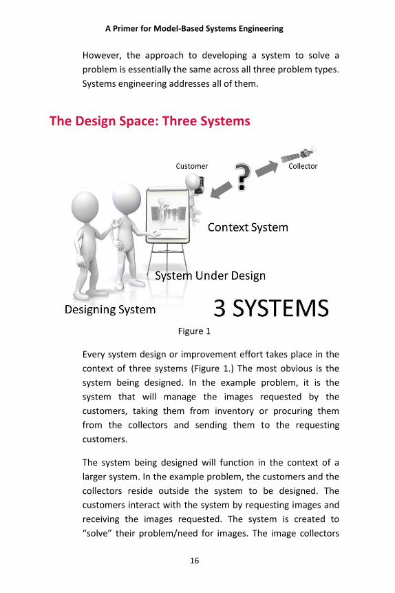
The Design Space: Three Systems
Figure 1
Every system design or improvement effort takes place in the
context of three systems (Figure 1.) The most obvious is the
system being designed. In the example problem, it is the
system that will manage the images requested by the
customers, taking them from inventory or procuring them
from the collectors and sending them to the requesting
customers.
The system being designed will function in the context of a
larger system. In the example problem, the customers and the
collectors reside outside the system to be designed. The
customers interact with the system by requesting images and
receiving the images requested. The system is created to
“solve” their problem/need for images. The image collectors
A Primer for Model-Based Systems Engineering
17
interact with the system by accepting tasking from the system
and returning images in response. Both customers and
collectors are part of the greater contextual system in which
the system under design “lives and works.” This contextual
system is the second of the three systems.
The third and final system is the system that is used to design
the system and bring it into being. This system is critical
because it drives the quality and ultimate success of the
design. This is the system that must understand the other two
systems and must at the same time be “self-aware.” It is only
through this self-awareness that the design can take on its full
measure of intentionality and manage the considerations
manifested in the other two systems.
In one of the more interesting and helpful variants of the
design space discussion, James Martin posits seven systems.
He titles his article “The Seven Samurai of Systems
Engineering: Dealing with the Complexity of 7 Interrelated
Systems” as an allusion to the Japanese movie The Seven
Samurai, in which seven samurai warriors fight to save a small
Japanese village (http://www.incose.org/wma/library/
docs/Seven_Samurai-Martin-paper-v040316a.pdf). Martin
suggests that, properly employed, the seven systems he sees
in the design space can become the key to design success.
Martin’s systems are the Context System, the Intervention
System, the Realization System, the Deployed System, the
Collaborating System, the Sustainment System, and the
Competing System. He summarizes their interactions as
follows:
1. Context System contains a Problem.
2. Intervention System is intended to address Problem.
3. Realization System brings Intervening System into being.
4. Intervening System is a constituent of Realization System.
A Primer for Model-Based Systems Engineering
18
5. Realization System needs to understand Context System.
6. Realization System needs to understand the Modified
Context System.
7. Realization System may need to develop or modify the
Sustainment System.
8. Intervention System becomes Deployed System.
9. Context System becomes the Modified Context System.
10. Deployed System is contained in Context System.
Deployed System collaborates with one or more
Collaborating Systems.
11. Deployed System is sustained by Sustainment System.
12. Deployed System may cause new Problem.
13. Competing Systems may address the original Problem.
14. Competing Systems compete with Deployed System for
resources and for the attention of users and operators.
Looking at the relationships and systems posited by Martin
shows a clear mapping back to the simpler three-system
model. The Context System in both Martin’s model and the
three-system model contains the problem from the outset and
will contain the Deployed System once it is designed.
Collaborating and Competing Systems also reside there. When
the solution is deployed into the context, it will change the
Context System. Understanding all of this is critical for the
systems engineers to successfully create an acceptable design
solution.
The whole issue of unintended consequences is an example of
the failure to completely understand the Context System. Take
as an example the introduction of nutria (a large South
American rodent) as an “answer” to the need to produce
quality fur more quickly and inexpensively. The following
advertisement (Figure 2) frames the problem and solution that
led to importing large numbers of nutria into the United
States.

A Primer for Model-Based Systems Engineering
19
Figure 2
In the advertisement, nutria are touted as being productive
(their fur next to mink in price); prolific (producing 15 to 20
young per year); easy to raise; inexpensive (costing only 1 ½
cents per day for food), as well as climate tolerant and disease
resistant. However, it fails to address what turned out to be a
major problem. The nutria reproduced rapidly and shortly
“breached containment,” escaping into the wild. Their
reproduction rate, climate tolerance, and disease resistance
made them formidable competitors in the wild. Soon they
were driving out indigenous species and defoliating the
habitats. Significant damage is being done to the areas where
they have established themselves.
The “systems engineers” at companies like Cabana Nutria, Inc.
understood the problem and addressed it directly. What they
failed to understand and address was the Context System
beyond the problem space. An effective solution to the
problem created a much bigger problem as an unintended and
unforeseen consequence of its application.
A Primer for Model-Based Systems Engineering
20
Even more insidious is the failure to account for the design
system, what Martin calls the Realization System. Inattention
to this system can cause a failure of discipline and rigor. It
cannot be said too often in the world of systems engineering
that we don’t know what we don’t know. A failure to use a
disciplined or convergent process will lead to errors that will
be completely transparent to those who make them. They are
transparent precisely because of the failure to use the
discipline that would allow the designer to catch them.
Without a rigorous, disciplined system for design, there is no
way to be sure that the design considers all aspects of the
Context System.
The metaphor of three systems is simple, but its message is
clear—systems design must consider not only the system
being designed but its context and its method of design as
well. Failure to take any of the three into account is a recipe
for failure.
The Design Space: Boundaries
Once the systems engineer grasps the concept of the three
systems, she must come to grips with the boundary between
the system being designed and the system it will live in. The
former is within the “control” of the design process, and the
latter is simply present and must be adapted to.
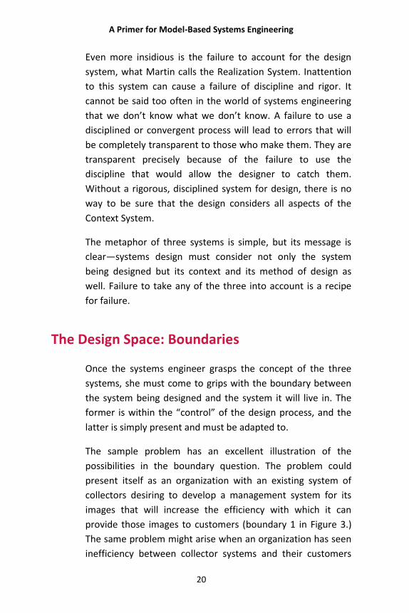
The sample problem has an excellent illustration of the
possibilities in the boundary question. The problem could
present itself as an organization with an existing system of
collectors desiring to develop a management system for its
images that will increase the efficiency with which it can
provide those images to customers (boundary 1 in Figure 3.)
The same problem might arise when an organization has seen
inefficiency between collector systems and their customers
A Primer for Model-Based Systems Engineering
21
and recognized the business opportunity to bridge that gap by
providing a way to reduce the inefficiency (boundary 2 below.)
A third possibility might exist if the customer recognized that
he could reduce his costs and wait time by managing the
images already produced and seeking to engage the collectors
for “new” images (boundary 3 below.)
In each case the system boundary is drawn differently for the
design process.
Figure 3
In each of these three cases, the degree of vertical integration
helps determine the system boundaries. It is clear that it is
very important to have a well-defined view of those
boundaries, because no matter which boundary case applies
to the situation confronting the design team, it is important to
understand the nature of the problem in connecting the
customers to the Geospatial Library and through it to the
collectors. The design of those connections turns on the
location of those boundaries.
The Process
The first task of the systems engineer is to develop a clear
statement of the problem, setting out what issue or issues are
being addressed by the proposed system. This involves
working with others (especially system stakeholders and
subject-matter experts) to identify the stated requirements
that govern what would characterize an acceptable solution.
A Primer for Model-Based Systems Engineering
22
The systems engineer must provide design focus and facilitate
proper and effective communication between the various
subject-matter experts and the stakeholders. The systems
engineer must have a broad knowledge base in order to
understand the various disciplines involved in developing the
system, to participate in and evaluate system-level design
decisions, and to resolve system issues. Often some system
requirements conflict with each other. When this happens,
the systems engineer must resolve these conflicts in a way
that does not lose sight of the system’s purpose. The goal of
the engineer is to develop a system that maximizes the
strengths and benefits of the system while minimizing its flaws
and weaknesses.
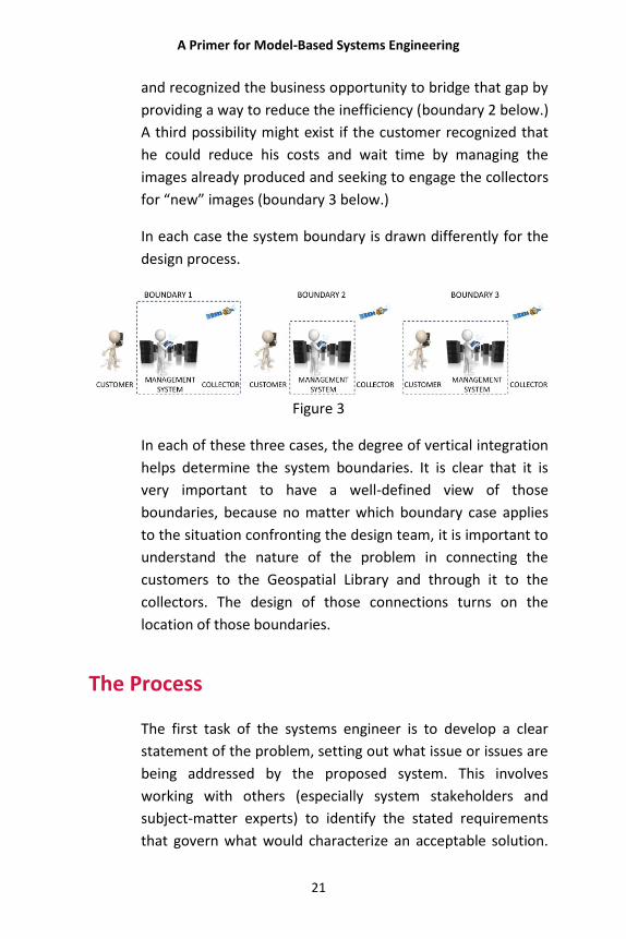
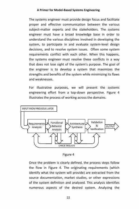
For illustrative purposes, we will present the systems
engineering effort from a top-down perspective. Figure 4
illustrates the process of working across the domains.
Figure 4
Once the problem is clearly defined, the process steps follow
the flow in Figure 4. The originating requirements (which
identify what the system will provide) are extracted from the
source documentation, market studies, or other expressions
of the system definition and analyzed. This analysis identifies
numerous aspects of the desired system. Analyzing the
A Primer for Model-Based Systems Engineering
23
requirements allows the systems engineer to define the
system boundaries and identify what is inside and outside
those boundaries. The definition of these boundaries—an
often overlooked step—is critical to properly implementing
the system. Any change in the system boundaries will affect
the complexity and character of the way in which the system
interacts and interfaces with the environment.
Specifying the functional requirements and the interactions of
the system with the external entities is essential and leads
directly to developing a clear picture of the system. It is critical
that the functional requirements (the “what”) are understood
before attempting to define the implementation (the “how”)
of the system. Therefore, this analysis is repeated throughout
the system design process to test the rigor and integrity of the
system.
The “how” of the system is embodied in the functional
behavior. This behavior is designed to meet the requirements
as they have been laid out. Every requirement is the basis of
one or more behaviors, and every behavior is based on one or
more requirements. This is the backbone of the bidirectional
traceability that will ultimately guarantee that the system
design meets the system requirements.
In parallel with the functional behavior definition, what must
be built to perform the needed behavior is derived through
decomposing the system into components. The systems
engineer then analyzes the constraints and allocates system
behavior to the physical components. This leads to the
specification of each system component. As a result of this
allocation, the identification and definition of all interfaces
between the physical parts of the system—including
hardware, software, and people—can take place. These design
decisions create the physical architecture of the system.
A Primer for Model-Based Systems Engineering
24
Once the physical architecture has been created and the
behavior allocated to it, the system must be tested.
Verification and validation are both aspects of that testing.
The system is verified against the performance standards and
specifications, and the design is validated against the
requirements. In this way the engineering team can be certain
that the design is indeed what is called for in satisfying the
customers’ needs.
It should be emphasized that these activities are performed
concurrently or in sequence but not independently. The
activities in one area influence, and are influenced, by the
other activities.
This look at the systems engineering process uses a
description that best fits top-down systems design. With
suitable approach variations, the systems engineer can
address reverse (or bottom-up) and middle-out systems
engineering perspectives as well. For example, in conducting
reverse engineering, the engineer would begin with the
existing physical description and work from the physical
representation and interfaces to ultimately derive the original
system’s requirements. Once these are obtained, the
engineering process would proceed to incorporate the desired
changes and enhancements as in a top-down design.
Domains
As described above, the work on the design proceeds in four
domains: requirements, functional behavior, architecture, and
verification and validation. Often these domains are treated as
discrete efforts. In the classic approach, work in the domains
proceeds in order, with the goal of finishing each one in turn.
In this instance the process we have described moves
sequentially through these domains.
A Primer for Model-Based Systems Engineering
25
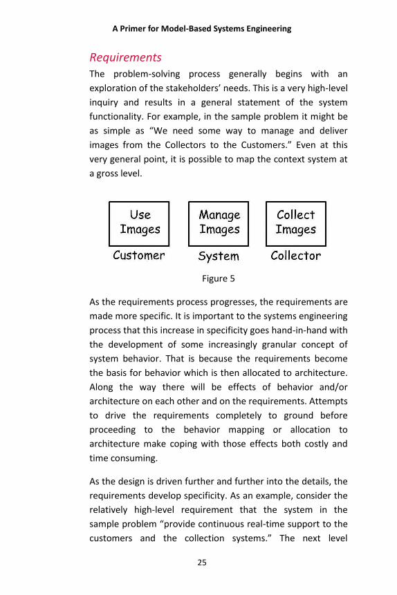
Requirements The problem-solving process generally begins with an
exploration of the stakeholders’ needs. This is a very high-level
inquiry and results in a general statement of the system
functionality. For example, in the sample problem it might be
as simple as “We need some way to manage and deliver
images from the Collectors to the Customers.” Even at this
very general point, it is possible to map the context system at
a gross level.
Figure 5
As the requirements process progresses, the requirements are
made more specific. It is important to the systems engineering
process that this increase in specificity goes hand-in-hand with
the development of some increasingly granular concept of
system behavior. That is because the requirements become
the basis for behavior which is then allocated to architecture.
Along the way there will be effects of behavior and/or
architecture on each other and on the requirements. Attempts
to drive the requirements completely to ground before
proceeding to the behavior mapping or allocation to
architecture make coping with those effects both costly and
time consuming.
As the design is driven further and further into the details, the
requirements develop specificity. As an example, consider the
relatively high-level requirement that the system in the
sample problem “provide continuous real-time support to the
customers and the collection systems.” The next level
A Primer for Model-Based Systems Engineering
26
question becomes “What is continuous real-time support?”
The requirement is refined to answer that question by
defining it as “The system shall be unavailable no more than a
total of 10 minutes per month.” Each of the requirements is
the basis of behavior that increases in specificity with the
requirements.
Behavior System behavior is concerned with two fundamental system
characteristics: what the system must do in order to answer
the customer’s need and how well the system must perform
these functions. In the example above what the system must
“do” is be available to customers and collectors. The standard
of performance (the “how well” it must perform) in this case is
to the level of no more than 10 minutes of unavailability a
month.
Describing behavior to meet requirements is constructing the
system logic or the logical model. Often this is done in one
step with the architecture design. The systems engineer
attempts to allocate the requirements directly to the
capability of an architectural component or components.
Recognizing this as “doing” behavior in one step with
architecture is probably being excessively charitable to that
process. It is more appropriate to acknowledge that it simply
skips the behavioral or logical step.
Separating the logical model from the physical model offers
distinct advantages to the systems engineering team. The
primary advantage is that the team does not have to assign
behavior to components prematurely, something which
complicates the system design effort. Separating these
simplifies the design effort and enhances the likelihood of
finding the best balance of functionality, performance, and
component composition. Once the behavior is in place, it
A Primer for Model-Based Systems Engineering
27
becomes appropriate to consider the architecture to which it
is to be allocated.
Architecture System architecture/synthesis is concerned with what physical
structure offers the best balance—considering manufacturing,
testing, support, and other factors—in answering the
customer’s need for the system. At its heart is the realizability
of the system and its physical complexity. (Is it
manufacturable, maintainable, and supportable?)
These aspects of the system strongly correlate with the
system’s behavior and the resulting partitioning and allocation
of behavior to subordinate physical components.
Architecture/synthesis tends to follow behavior in
development (form follows function) rather than the other
way around, because behavior more fully captures the
features of what the system does. There is, however, an
important “but.”
Many systems have significant architectural constraints, which
limit the systems engineer’s choices regarding architectural
composition. These constrain system behavior and therefore
lead the way instead of following. They may even reach a level
where it becomes clear that choices need to be made
between competing requirements which impose mutually
exclusive physical constraints. Such constraints are
encountered at the point of architectural design and need to
be translated back into the behavior (and sometimes even the
requirements) domain (e.g., an aircraft whose specified
operational range requires it to carry such a large load of fuel
that it is too large for the short-field operations called for in
the initial requirements).
A Primer for Model-Based Systems Engineering
28
Verification and Validation At the conclusion of the systems development phase of the
system life cycle, the customer must accept or reject the
delivered system. Depending upon the situation, the customer
may choose one or more methods to determine whether the
system fulfills the requirements of the development contract.
The goal in any case is to assure that the design process has
converged on a complete and workable solution to the entire
problem posed to the design team. The process for doing this
is known as verification and validation. Verification and
validation are the two aspects of answering the acceptance
question. Both of these aspects need to be considered
throughout the design and development processes. Program
management and engineering management teams need to
plan and address the measures that will lead to achieving
customer acceptance.
Verification is a “quality” process used to evaluate whether or
not a product, service, or system complies with particular
regulations, specifications, or conditions. Verification may
occur anywhere in the system’s life cycle. Verification is often
an internal process, but external and independent
verifications can also occur.
While validation is the process of establishing necessary and
sufficient evidence that a product, service, or system satisfies
its established requirements, formal validation often includes
the confirmation of fitness for use from the viewpoints of
customers, end users, and other product stakeholders as an
acceptance criterion. The ultimate validation question
becomes: “Does this system, as built, satisfy the needs which
drove the instigation of the design project?”
NOTE: More and more systems engineering teams think of the
process of measuring the efficacy of the system design as Test
A Primer for Model-Based Systems Engineering
29
and Evaluation (T&E). This concept arises from the software
development world and seeks to document the scope,
content, and methodology for test activities. It is embodied in
a test plan which describes the test activities of the subsystem
integration test, the system test, the user acceptance test, and
the security test in progressively higher levels of detail as the
system is developed. (As we shall see, this makes T&E a
natural fit with the layered MBSE approach.) Although T&E is
different from classic V&V, they are similar enough that for
the purposes of this primer we will treat them as the same.
Communication
It is easy to see that these four domains cover a variety of
disciplines. From gathering the requirements from an often
diverse community of system users and owners to specifying
technical architectures that will cover complex capabilities,
the systems engineering team must be able to communicate
the problem and the potential solutions in ways that will be
universally understood.
In the sample problem, the customers who use the images will
be experts at interpreting the information in the images,
visualizing terrain and recognizing infrastructure and human
activity. They will understand what images they need and
what those images should contain. They will not necessarily be
familiar with the technology necessary to allow them to
phone, fax, deliver, or directly request the images they need.
The designers of the library will understand how to use the
image data and metadata to organize, store, and retrieve the
images but will not know the technical details of the
alternative ways in which the images can be brought into the
library from the collectors’ information stream. Bridging these
A Primer for Model-Based Systems Engineering
30
gaps and many others is the job of the systems engineering
team.
This requires careful and nuanced communication. There must
be attention to language, and a common understanding of the
use of language must be developed across the design and the
disciplines involved in creating it. This coordination and
communication challenge makes the effective practice of
systems engineering a challenge in both the management and
technical arenas.
The successful systems engineering team must maintain a
systems view while moving through the four domains.
Stakeholder needs are the source of system requirements.
Those requirements become the basis of system behavior.
That behavior is allocated to the physical architecture, which is
then judged back against the requirements. Along the way,
the team must craft that solution which best fits the context
for it and do so using a disciplined and effective design
process.
A Primer for Model-Based Systems Engineering
31
WHAT IS A MODEL?
Models are common to human experience as aids for
understanding the way the world works. Everyone has
experience with some form of model and therefore has some
preconceived notions of what constitutes a “good” model.
Children’s toys are simple models of the world around them.
Toy cars, trains, and dolls all typically characterize forms,
playing on the child’s ability to link imagination (an abstract
representation) to a real object. In this sense the word model
means a physical representation of an abstract idea.
Models span a spectrum running from form to function. On
one end are tangible, visible models like a child’s plastic toy
airplane. It mimics, or models, the physical appearance of the
object (the full-sized airplane) that it represents. It doesn’t
fly—or if it does it doesn’t do so in the way the actual object
does. It models the form of the plane but not the function.
On the other end of the spectrum are model forms existing
only as sets of equations or simulations implementing the
equations. Rather than visually representing the reality behind
them, these models allow us to examine such things as the
behavior of the object being modeled. One common
characteristic of such models is that they capture or
emphasize only certain properties of interest in the modeled
object, while the fidelity of the model to the actual object is
intentionally reduced or limited in other ways.
In the world of engineering design, models connect the idea
behind a design solution with its implementation as a real
system. These models attempt to represent the entities of the
engineering problem (opportunities) and their relationships to
each other and connect them to the proposed solution or
A Primer for Model-Based Systems Engineering
32
existing mechanism that addresses the problem. The model
used in this way is the centerpiece of MBSE.
Four Elements of a Model
There are four elements of such a model: language, structure,
argumentation, and presentation.
Language—The model is seen in terms of language. The
system definition language (SDL) expresses and represents the
model clearly, so that understanding and insight can arise. This
is critical to successful system design. The system definition
language must be clear and unambiguous in order to depict
the model accurately and understandably.
Structure—The model must have structure. This allows the
model to capture system behavior by clearly describing the
relationships of the system’s entities to each other.
Argumentation—The purpose of the model is to represent the
system design in such a way that the design team can
demonstrate that the system accomplishes the purposes for
which it is designed. Therefore the model must be capable of
making the critical “argument” that the system fulfills the
stakeholders’ requirements.
Presentation—Not only must the system be capable of
making that argument, but it must include some mechanism
of showing or “presenting” the argument in a way that can be
seen and understood.
These elements, language, structure, argumentation, and
presentation, give the MBSE model what it needs to serve the
purpose of testing the system design solution against the
requirements in a way that proves its fitness and presents that
A Primer for Model-Based Systems Engineering
33
proof for all to see. This is the distinguishing value of the
model.
Characteristics of a Model
There are four characteristics common to successful system
models. These are order, the power to demonstrate and
persuade, integrity and consistency, and the ability to provide
insight into both the problem and its potential solutions.
Order—Order allows the design team to attack the problem in
a coherent and consistent manner leading to a viable solution.
The model provides the order that becomes the framework
for this effort.
Power to Demonstrate and Persuade—By representing the
relevant behaviors in proper relationship to the system
entities, the model allows the designer to see and
demonstrate the necessary system behavior. This becomes
persuasive in making the case that a given solution answers
the needs that drive the design of the system.
Integrity and Consistency—Ambiguity and inconsistency in
the system design lead to design flaws which, in turn, harm
the credibility of the argument that the system design meets
the needs it was designed to meet. The model must,
therefore, provide the integrity and consistency that lead to a
sound solution.
Insight—The model provides insight into the system problem
facing the design team as well as the potential design
solutions. By the model’s representation of system behaviors
and relationships, the design team is able to gain insight into
the comparative advantages of different approaches to solving
the design problem at hand.
A Primer for Model-Based Systems Engineering
34
Caveat: A Set of Views Is NOT a Model Various graphical and textual views derived from the true
systems model are sometimes treated as if they were
themselves models. However, these are, at most, viewable
projections of the underlying model. That is, they contain
some subset of entities, attributes, and relationships
presented so that the engineer, reader, or reviewer gains
insight into a particular aspect or aspects of the system design.
Graphical or textual views, in themselves, are not sufficient to
constitute a model. They are, rather, expressions of the model
being represented.
To be a true model, the system model needs to manage the
depth, breadth, and associated boundary conditions of the
system. This is not possible with a view or even a set of views.
Views are a valuable tool for understanding, analyzing, and
communicating the model. Some sets of views even offer a
broad understanding of many system aspects. But the views
themselves are not a model.
Language: The Systems Model Is Language-
Based
The relationship between the language expressing the model
and the meaning conveyed in the model is critically important.
Language is critical to disciplined systems design. The
ambiguity and lack of clarity that are so often present in
design efforts can have crippling results which can render a
system design useless. The need for a clear, unambiguous
systems definition language is only enlarged by the presence
of a diversity of disciplinary experts required to assist in a
complete design. The language will include both the symbolic
representation of system concepts and the graphic views and
representations that are used to convey the functions and
A Primer for Model-Based Systems Engineering
35
behaviors embodied in the system. After choosing a particular
reference entity of a given class, the use of the definition
language enables the engineering team to ask the right
question at the right time. A tremendous advantage for
resolving issues, this avoids unnecessary or inappropriate
work. A common language that can give full expression to the
system in its entirety is essential to a successful design and to
making the case to the stakeholders that the design actually
meets the requirements posed in the problem that drives the
design.
The model must be much more than one or more graphical
representations. It must take on the difficult tasks of
representing the system’s relationships in a way that assures
traceability and the consistency of boundary conditions across
the domains. The model is therefore captured in a language in
a way that allows the engineer to determine and
communicate the system characteristics. These characteristics
drive the way the system’s components interact within the
system and with the system’s external environment.
Another aspect of a system as a whole is that it cannot be
divided into independent parts without losing some of its
essential characteristics. Thus, a system’s essential defining
properties are the products of the interactions of its parts, not
the sum of the actions of the parts considered separately. This
means that a successful system language must be able to
capture these essential interactions in a way that accurately
depicts this synergy.
Sometimes there are kinds of behavior and properties that the
system must exclude. These exclusions are as much a part of
the system definition as those that are included. Safety and
security properties fall into this realm. The system must not be
unsafe to users. It must not be vulnerable to specific threats.
The model must be clear in expressing whether or not these
A Primer for Model-Based Systems Engineering
36
system properties will or will not be present. This is
particularly true because the properties of individual
components are not necessarily present in the system.
Graphics by themselves have only a limited ability to convey
these characteristics and assurances. This is one of the
fundamental reasons for needing an expression of the model
that extends beyond mere graphic representations.
A model is an integrated expression of the system using the
system definition language (SDL). It comprises source or
originating properties (e.g., context, purpose, environment,
and other constraints), physical properties (e.g., size, weight,
power), behavioral properties (e.g., events, time sequencing
of observables, execution conditions, performance), relevant
analytical and test information, and the relationships between
these system entities.
Other characteristics are necessary for a successful systems
language such as the system definition language. It must be
relatively easy for a diverse population to understand it, while
at the same time it must be able to deal with the necessary
levels of abstraction. Not everyone possesses the knowledge
to understand every nuance of the system model. Therefore,
the SDL language needs to use a basic vocabulary without a
multiplicity of meanings.
With SDL, the specialty language of domain experts is avoided;
yet domain experts can easily relate the SDL to their domain
of expertise. The mapping in Figure 7 (page 38) represents the
relationship of the parts of speech from common language to
model-based systems engineering SDL.
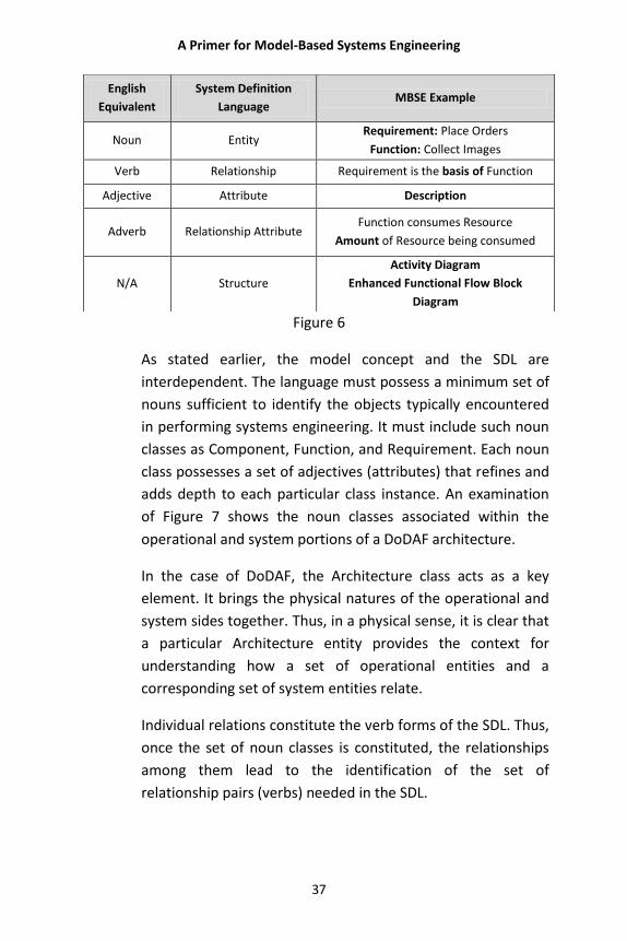
A Primer for Model-Based Systems Engineering
37
Figure 6
As stated earlier, the model concept and the SDL are
interdependent. The language must possess a minimum set of
nouns sufficient to identify the objects typically encountered
in performing systems engineering. It must include such noun
classes as Component, Function, and Requirement. Each noun
class possesses a set of adjectives (attributes) that refines and
adds depth to each particular class instance. An examination
of Figure 7 shows the noun classes associated within the
operational and system portions of a DoDAF architecture.
In the case of DoDAF, the Architecture class acts as a key
element. It brings the physical natures of the operational and
system sides together. Thus, in a physical sense, it is clear that
a particular Architecture entity provides the context for
understanding how a set of operational entities and a
corresponding set of system entities relate.
Individual relations constitute the verb forms of the SDL. Thus,
once the set of noun classes is constituted, the relationships
among them lead to the identification of the set of
relationship pairs (verbs) needed in the SDL.
English
Equivalent
System Definition
Language MBSE Example
Noun Entity Requirement: Place Orders
Function: Collect Images
Verb Relationship Requirement is the basis of Function
Adjective Attribute Description
Adverb Relationship Attribute Function consumes Resource
Amount of Resource being consumed
N/A Structure
Activity Diagram
Enhanced Functional Flow Block
Diagram
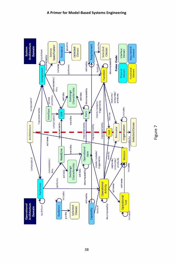
A Primer for Model-Based Systems Engineering
38
Figu
re 7
A Primer for Model-Based Systems Engineering
39
The directional lines in Figure 7 illustrate some of the primary
SDL relations. These relations are directional. This means that
in forming a “sentence,” the noun class at the arrow’s tail is
the subject of the sentence and the noun class at the arrow’s
head is the direct object (e.g., Architecture is “composed of” a
Component). Such a sentence expresses a “relationship.”
The types of problems encountered determine the types of
nouns, verbs, adjectives, and adverbs needed in the SDL. The
solvable problems need language entities to define both the
problem and solution. The fundamental structure of the SDL
does not change, but vocabulary (nouns, verbs, adjectives, and
adverbs) should be tailored to the domain. The definition of
the system definition language structure and vocabulary is
critical to having a successful system design.
Language of Behavior
The need for a language to express the system design applies
to all aspects of the design. This includes the representation of
behavior. The language of behavior is graphical. It must reflect
the time-dependent and time-independent aspects of system
behavior, the sequencing of functions, resource management,
interfaces, and control behavior.
The criteria necessary for showing behavior graphically require
that the graphical language (notation) possesses certain
characteristics. These characteristics are:
A Primer for Model-Based Systems Engineering
40
1. The ability to capture process flow and control
2. The ability to capture observables
3. Understandability
4. Executability
5. The ability to preserve behavior across:
a. Decomposition
b. Aggregation
c. Allocation
The system definition language functions and items are both
decomposable. Items represent the inputs and outputs of
functions—the observables. Any system may be described in
terms of “black boxes.” A black-box view just addresses the
inputs and outputs to the system, including their sequencing
and timing. Such a system is also decomposable into a set of
black boxes.
It is important that any decomposition (or aggregation) not
lose the behavioral effects of the layer from which it is based.
For example, the behavioral consequences of a trigger (an
input that enables the function to begin) should be preserved
into the next layer upon decomposition and not be “lost.”
Preservation of behavior is, therefore, an important property
of both the graphical language and the system definition
language.
For example, in the Geospatial Library design, one of the high-
level system requirements calls for the system to “accept
requests from certified customers.” As the design is fleshed
out, it becomes apparent that customers need to make
requests in a variety of media formats. The requirement to
accept requests from certified customers must encompass
these formats, so it becomes a requirement to “accept
requests from certified customers via any of the following
media: (1) hardcopy forms, (2) verbal, (3) phone-verbal, (4)
phone–electronic file, and (5) PC diskette–electronic file.”
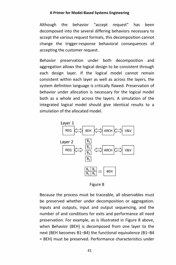
A Primer for Model-Based Systems Engineering
41
Although the behavior “accept request” has been
decomposed into the several differing behaviors necessary to
accept the various request formats, this decomposition cannot
change the trigger-response behavioral consequences of
accepting the customer request.
Behavior preservation under both decomposition and
aggregation allows the logical design to be consistent through
each design layer. If the logical model cannot remain
consistent within each layer as well as across the layers, the
system definition language is critically flawed. Preservation of
behavior under allocation is necessary for the logical model
both as a whole and across the layers. A simulation of the
integrated logical model should give identical results to a
simulation of the allocated model.
Figure 8
Because the process must be traceable, all observables must
be preserved whether under decomposition or aggregation.
Inputs and outputs, input and output sequencing, and the
number of and conditions for exits and performance all need
preservation. For example, as is illustrated in Figure 8 above,
when Behavior (BEH) is decomposed from one layer to the
next (BEH becomes B1–B4) the functional equivalence (B1–B4
= BEH) must be preserved. Performance characteristics under
A Primer for Model-Based Systems Engineering
42
decomposition need to be carefully managed. Performance
measures may change at different levels of decomposition and
performance characteristics, especially time performance
values, may need decomposition as well.
Managing Complexity with Language
Separating the functional/behavioral domain from the
architecture/synthesis domain is one of several means of
managing complexity in model-based systems engineering.
The logical model is one that, over time, changes little, if at all;
while the physical model changes rapidly due to technological
and other advances. Using the principle of allocation, many
alternative physical configurations may be tried to find the
best balance among a diverse set of criteria. Later in the
system life cycle, if the physical structure needs to change, it
becomes relatively easy using the model to discover what
functions are affected by a physical change and vice versa.
Conversely, if a requirement change occurs, then its impact on
the functional model and physical models is also easily
discovered because of the traceability afforded by the system
definition language.
There are a number of diagrams currently used to support the
behavioral domain in systems engineering. The more
prevalent views are shown in Figure 9. Several structure
diagrams capture the logical sequencing of functions, events,
and control flow. These are the Functional Flow Block Diagram
(FFBD), the Enhanced Functional Flow Block Diagram (EFFBD),
and the Activity Diagram.
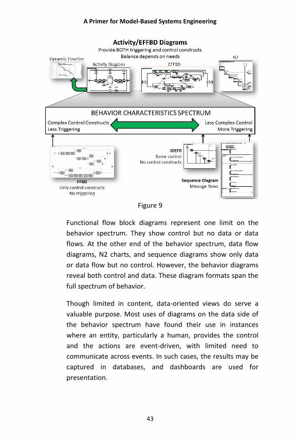
A Primer for Model-Based Systems Engineering
43
Figure 9
Functional flow block diagrams represent one limit on the
behavior spectrum. They show control but no data or data
flows. At the other end of the behavior spectrum, data flow
diagrams, N2 charts, and sequence diagrams show only data
or data flow but no control. However, the behavior diagrams
reveal both control and data. These diagram formats span the
full spectrum of behavior.
Though limited in content, data-oriented views do serve a
valuable purpose. Most uses of diagrams on the data side of
the behavior spectrum have found their use in instances
where an entity, particularly a human, provides the control
and the actions are event-driven, with limited need to
communicate across events. In such cases, the results may be
captured in databases, and dashboards are used for
presentation.
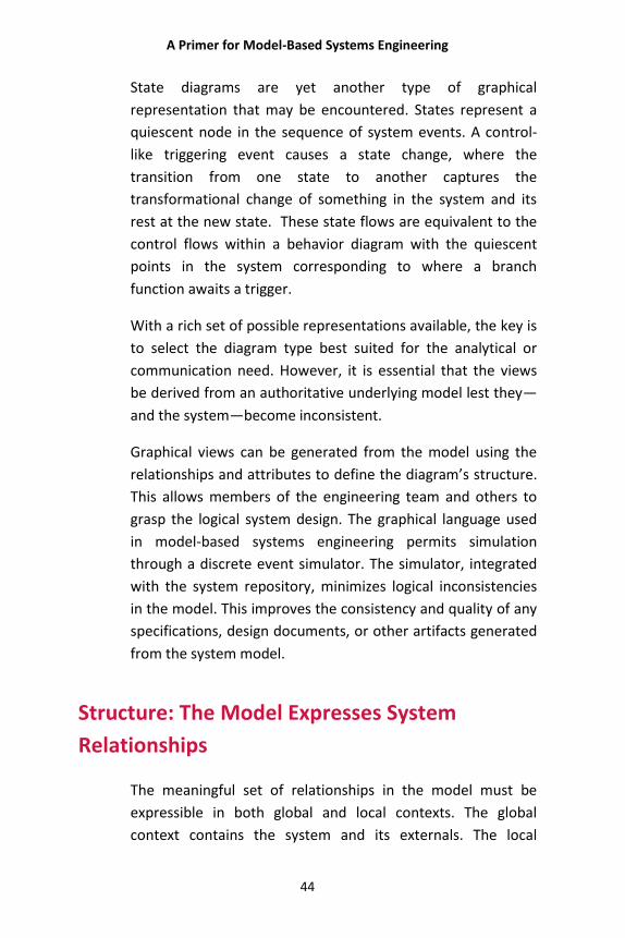
A Primer for Model-Based Systems Engineering
44
State diagrams are yet another type of graphical
representation that may be encountered. States represent a
quiescent node in the sequence of system events. A control-
like triggering event causes a state change, where the
transition from one state to another captures the
transformational change of something in the system and its
rest at the new state. These state flows are equivalent to the
control flows within a behavior diagram with the quiescent
points in the system corresponding to where a branch
function awaits a trigger.
With a rich set of possible representations available, the key is
to select the diagram type best suited for the analytical or
communication need. However, it is essential that the views
be derived from an authoritative underlying model lest they—
and the system—become inconsistent.
Graphical views can be generated from the model using the
relationships and attributes to define the diagram’s structure.
This allows members of the engineering team and others to
grasp the logical system design. The graphical language used
in model-based systems engineering permits simulation
through a discrete event simulator. The simulator, integrated
with the system repository, minimizes logical inconsistencies
in the model. This improves the consistency and quality of any
specifications, design documents, or other artifacts generated
from the system model.
Structure: The Model Expresses System
Relationships
The meaningful set of relationships in the model must be
expressible in both global and local contexts. The global
context contains the system and its externals. The local
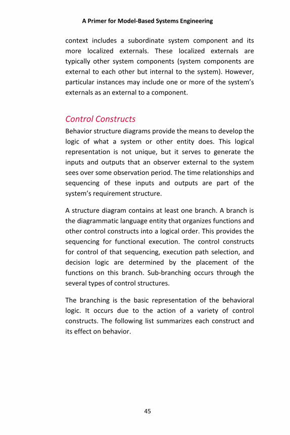
A Primer for Model-Based Systems Engineering
45
context includes a subordinate system component and its
more localized externals. These localized externals are
typically other system components (system components are
external to each other but internal to the system). However,
particular instances may include one or more of the system’s
externals as an external to a component.
Control Constructs Behavior structure diagrams provide the means to develop the
logic of what a system or other entity does. This logical
representation is not unique, but it serves to generate the
inputs and outputs that an observer external to the system
sees over some observation period. The time relationships and
sequencing of these inputs and outputs are part of the
system’s requirement structure.
A structure diagram contains at least one branch. A branch is
the diagrammatic language entity that organizes functions and
other control constructs into a logical order. This provides the
sequencing for functional execution. The control constructs
for control of that sequencing, execution path selection, and
decision logic are determined by the placement of the
functions on this branch. Sub-branching occurs through the
several types of control structures.
The branching is the basic representation of the behavioral
logic. It occurs due to the action of a variety of control
constructs. The following list summarizes each construct and
its effect on behavior.
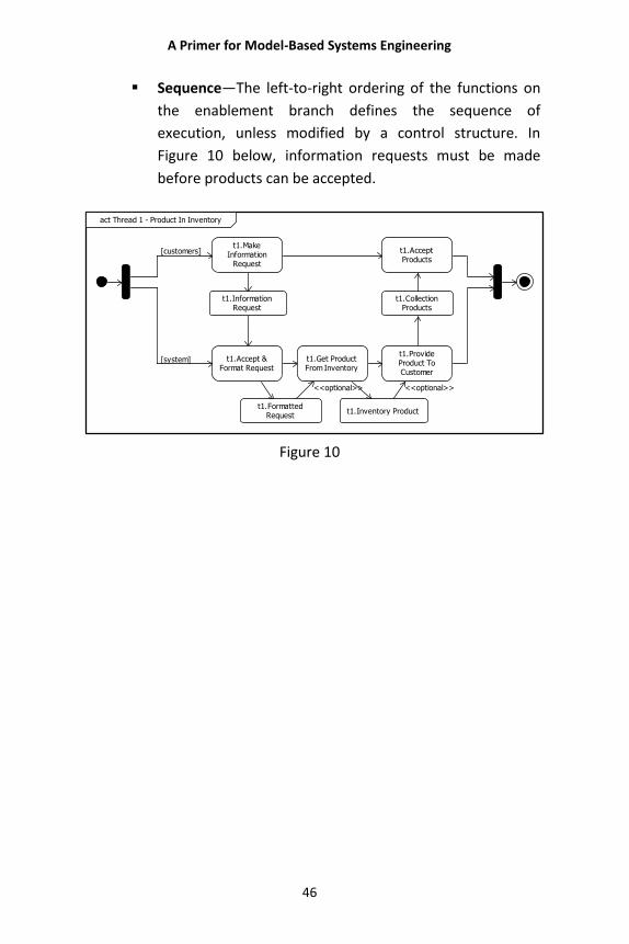
A Primer for Model-Based Systems Engineering
46
Sequence—The left-to-right ordering of the functions on
the enablement branch defines the sequence of
execution, unless modified by a control structure. In
Figure 10 below, information requests must be made
before products can be accepted.
[customers]
[system]
<<optional>> <<optional>>
t1.MakeInformation
Request
t1.AcceptProducts
t1.Accept &Format Request
t1.Get ProductFrom Inventory
t1.ProvideProduct ToCustomer
t1.InformationRequest
t1.CollectionProducts
t1.FormattedRequest
t1.Inventory Product
act Thread 1 - Product In Inventory
Figure 10
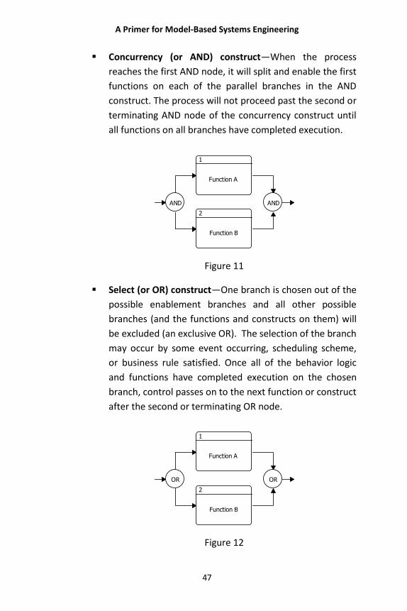
A Primer for Model-Based Systems Engineering
47
Concurrency (or AND) construct—When the process
reaches the first AND node, it will split and enable the first
functions on each of the parallel branches in the AND
construct. The process will not proceed past the second or
terminating AND node of the concurrency construct until
all functions on all branches have completed execution.
AND
1
Function A
2
Function B
AND
Figure 11
Select (or OR) construct—One branch is chosen out of the
possible enablement branches and all other possible
branches (and the functions and constructs on them) will
be excluded (an exclusive OR). The selection of the branch
may occur by some event occurring, scheduling scheme,
or business rule satisfied. Once all of the behavior logic
and functions have completed execution on the chosen
branch, control passes on to the next function or construct
after the second or terminating OR node.
OR
1
Function A
2
Function B
OR
Figure 12
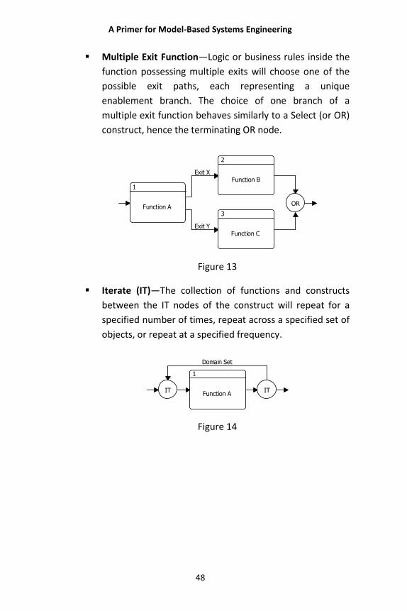
A Primer for Model-Based Systems Engineering
48
Multiple Exit Function—Logic or business rules inside the
function possessing multiple exits will choose one of the
possible exit paths, each representing a unique
enablement branch. The choice of one branch of a
multiple exit function behaves similarly to a Select (or OR)
construct, hence the terminating OR node.
Exit Y
Exit X
1
Function A
2
Function B
3
Function C
OR
Figure 13
Iterate (IT)—The collection of functions and constructs
between the IT nodes of the construct will repeat for a
specified number of times, repeat across a specified set of
objects, or repeat at a specified frequency.
Domain Set
IT
1
Function AIT
Figure 14
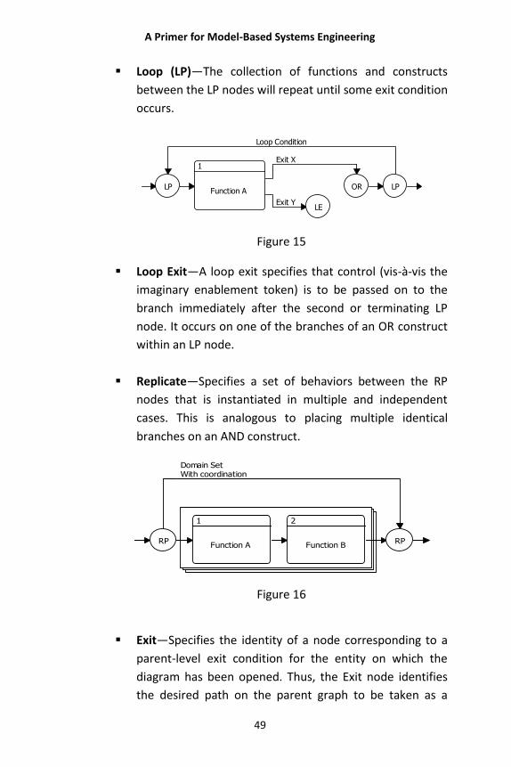
A Primer for Model-Based Systems Engineering
49
Loop (LP)—The collection of functions and constructs
between the LP nodes will repeat until some exit condition
occurs.
Exit Y
Exit X
Loop Condition
LP
1
Function A
LE
OR LP
Figure 15
Loop Exit—A loop exit specifies that control (vis-à-vis the
imaginary enablement token) is to be passed on to the
branch immediately after the second or terminating LP
node. It occurs on one of the branches of an OR construct
within an LP node.
Replicate—Specifies a set of behaviors between the RP
nodes that is instantiated in multiple and independent
cases. This is analogous to placing multiple identical
branches on an AND construct.
Domain SetWith coordination
RP
1
Function A
2
Function BRP
Figure 16
Exit—Specifies the identity of a node corresponding to a
parent-level exit condition for the entity on which the
diagram has been opened. Thus, the Exit node identifies
the desired path on the parent graph to be taken as a
A Primer for Model-Based Systems Engineering
50
result of reaching the exit node on the child behavior
diagram. The Exit node, therefore, represents the mapping
between internally represented exit behavior and the
externally represented exit branches for the parent
function.
Behavior is represented in activity or functional flow diagrams.
Both functional flow block diagrams—FFBDs and EFFBDs—and
activity diagrams are read from left to right. One helpful aid is
to follow an imaginary “enablement token” that starts on the
far left of the diagram. At an initial AND branch symbol the
imaginary token splits to follow each parallel branch. It will
move from left to right along the horizontal “enabled
branches” and enables, or allows, a function to execute when
the token reaches it. At the terminating AND branch symbol,
all the subordinate imaginary tokens are rejoined before the
token continues its journey.
At an initial OR branch symbol, the imaginary token advances
along only one branch (an exclusive OR). The selection of
which branch to follow is based on some event occurring
(perhaps as scheduled) or upon a business rule being satisfied.
Once all the branch functions have executed, the imaginary
token continues its journey.
In Figure 17, the product requested is NOT in inventory, so the
token takes the lower branch (Not in Inventory). It proceeds
through Prioritize Request and Determine Collector Mix to the
AND branching. There it divides to both Notify User of
Estimated Schedule and Task Collectors in parallel. The token
then moves to Accept and Format Collector Products and Put
Product in Inventory. It then proceeds to Get Product from
Inventory and divides again at the AND branching to both
Provide Product to Customer and Evaluate Products vs.
Request. The Product is OK, so the process continues on the
lower of the OR branches and reunites to finish the process.
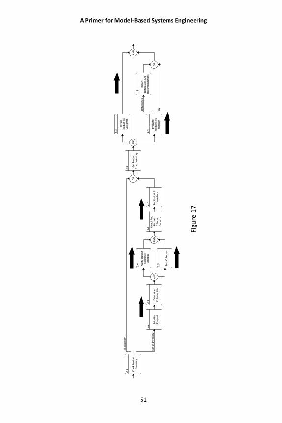
A Primer for Model-Based Systems Engineering
51
Figu
re 1
7
Not
In I
nvento
ry
In I
nvento
ry
OK
Defici
enci
es
2.1 Check
Pro
duct
Invento
ry
2.2
Prioritize
Request
2.3
Dete
rmin
eC
olle
ctor
Mix
AN
D
2.4 Notify
Use
r O
fEst
imate
dSch
edule
2.5 Task
Colle
ctors
AN
D
2.6 A
ccept
And
Form
at
Colle
ctor
Pro
duct
s
2.7 Put
Pro
duct
In
Invento
ry
OR
2.8 G
et
Pro
duct
Fro
m I
nvento
ryA
ND
1.3
Pro
vid
ePro
duct
To
Cust
om
er
1.4
Evalu
ate
Pro
duct
s vs.
Request
1.5
Report
Defici
enci
es
And
Reco
mm
endations
OR
AN
D
A Primer for Model-Based Systems Engineering
52
Branches are the way functional behavior is specified using an
EFFBD or activity diagram. Each of the different control
constructs has a unique effect on the flow of the enablement
token, which is how control constructs specify the control
logic.
These constructs serve as building blocks for the basic system
logic. However, there are two other modeling concepts that
affect functional behavior. These two modeling concepts are
the triggering of functions and provisioning of resources.
Triggers and resources are terms used in the system definition
language. Triggering is the determination of when a function
may execute on a branch once that branch is enabled.
Enablement in this sense means that all prior functions have
completed execution. A triggered function must wait for one
or more incoming, or triggering, items to be received before it
may execute. This is important when functions are allocated
to different components. Triggers serve as a means of
execution control under allocation. It is the means by which a
functionally allocated component knows when to begin
operation. (Triggering is often highlighted in sequence
diagrams, showing interactions between components but
without the clear specification of control.)
Resources also affect function execution. For example, if a
function exists to fire a missile, the firing (function) is
ineffective if there is no missile (resources) to fire. Modeling
resources accounts for a function becoming resource-starved
(no missile to fire) or having diminished performance where
its necessary resources are absent or degraded.
The activity diagram and enhanced functional flow block
diagram span the behavior spectrum and communicate the
logical steps that yield a given class of output for a given class
of input. The ordering of functions, which either perform or
A Primer for Model-Based Systems Engineering
53
contribute to the transformation, is important; just as word
ordering in an English sentence is important. Changing the
order of the functions, in general, changes the outcome; just
as changing the triggering events changes the ordering of the
outcomes. The result is that the graphical language is a special
case of the more general system definition language.
Argument: The Model Is Used to “Prove” the
Concept of the Design
The engineering team may consider different allocation
schemes to address any given engineering issue. Each
alternative offering will have certain benefits. The systems
engineering team examines, analyzes, and tests these
different allocations, as necessary, to achieve the best fit of
the benefits to the system. The allocation is measured with
consideration to a number of factors, including the system
requirements, the number and complexity of interfaces, and
life cycle costs, just to name a few. This analysis allows the
team to verify and select the alternative that offers the best
balance of performance, functionality, and usability in
satisfying the customer’s need. From that analysis, the
engineering team can create the picture needed as the basis
for verification and validation.
Bidirectional relationship sentences are used to reveal the
system’s interdependencies. (For example, A decomposes B,
implying that B is decomposed by A.) Such sentences advance
the model’s description and definition. Model advancement
means that the system unfolds in detail as the story-line
progresses.
In contrast to the world of document-based engineering, the
model’s reverse path allows the systems engineering team
A Primer for Model-Based Systems Engineering
54
and other stakeholders to unravel how the team reached a
particular point in the design effort. Horizontal linkages reveal
interrelated entities at the same complexity level. Vertical
linkages reveal relationships among various layers of
abstraction. The ability to express these system relationships
meaningfully allows the systems engineering team to manage
the complexity of the design and to identify and evaluate
impacts on other system entities. Document-based
approaches do not allow this (e.g., we cannot easily read a
book in reverse). This gives the model-based approach a
significant advantage over document-based approaches.
This advantage results because, with models, the system
design is advanced through levels of increasing detail and
demonstrates within itself how and why the system design will
satisfy the stakeholders’ needs. Therefore, a model is much
more than a graphic, a series of graphics, a set of tables,
simulation results, or even a collection of such things.
Presentation: The Model Must Be “Viewable”
This is the aspect of the model that places particular value on
graphical views. It is one thing to describe the model
abstractly and quite another to make the description real. For
most of us, this means some way to visualize the model in
three-dimensional space. Graphical views are helpful in
prompting that visualization.
All views are filtered for relevance to their purpose. No one
view contains the entire set of information. In fact, an attempt
to do that would rob the view of its power to make a
particular “statement” about the model by cluttering it up
with information not relevant to its purpose.
A Primer for Model-Based Systems Engineering
55
Graphical Representations The combination of the system design and the graphical
languages allows the model repository to generate a variety of
graphical views. Each view enhances and/or emphasizes some
system characteristics and suppresses others, giving the
engineering team a means of gaining different insights into
the system and its design. The functional flow block diagram
(FFBD) represents one limit of the behavior spectrum—where
only the control or logical structure of some portion of the
functional model is presented.
Figure 18 on page 56 shows a functional flow block diagram. In
this instance, there are two primary branches arranged as
concurrencies (a 2-branch AND construct). Each branch acts
independently of the other and may be activated by triggers,
but triggers are unseen in this view. Both branches need to
complete before exiting the behavior logic (the terminating
AND on the far right of the diagram). Rectangular icons
represent functions on this diagram. Also in this diagram are
two functions employing multiple exits. This is because some
decision occurs within these two functions.
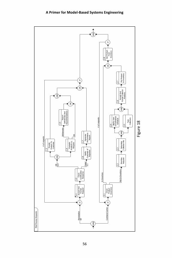
A Primer for Model-Based Systems Engineering
56
Figu
re 1
8
Com
mand C
ente
r
Not
In I
nvento
ry
In I
nvento
ry
# o
f re
quest
s
Work
station
kill
Faile
d0.1
OK
0.9
OK
Defici
enci
es
# o
f re
quest
s
AN
D
IT
1.1 A
ccept
And
Form
at
Request
1.2
Check
Cert
ific
ation
Resp
onse
AN
D
1.3
Pro
vid
ePro
duct
To
Cust
om
er
1.4
Evalu
ate
Pro
duct
s vs.
Request
1.5
Report
Defici
enci
es
And
Reco
mm
endations
OR
AN
D
1.6
Notify
Cust
om
er
of
Reje
ctio
n
1.7 G
enera
tePerf
orm
ance
Report
OR
IT
IT
2.1
Check
Pro
duct
Invento
ry
2.2
Prioritize
Request
2.3 D
ete
rmin
eC
olle
ctor
Mix
AN
D
2.4 N
otify
Use
rO
f Est
imate
dSch
edule
2.5
Task
Colle
ctors
AN
D
2.6
Acc
ept
And
Form
at
Colle
ctor
Pro
duct
s
2.7 Put
Pro
duct
In I
nvento
ry
OR
2.8 Get
Pro
duct
Fro
mIn
vento
ry
IT
AN
D
ffbd P
roce
ss R
equest
s
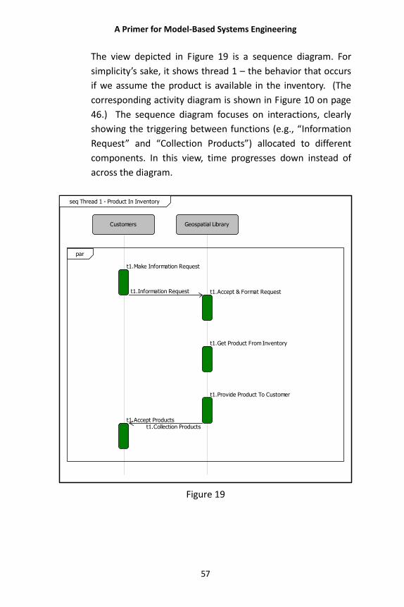
A Primer for Model-Based Systems Engineering
57
The view depicted in Figure 19 is a sequence diagram. For
simplicity’s sake, it shows thread 1 – the behavior that occurs
if we assume the product is available in the inventory. (The
corresponding activity diagram is shown in Figure 10 on page
46.) The sequence diagram focuses on interactions, clearly
showing the triggering between functions (e.g., “Information
Request” and “Collection Products”) allocated to different
components. In this view, time progresses down instead of
across the diagram.
Figure 19
par
Customers
t1.Make Information Request
t1.Accept Products
Geospatial Library
t1.Accept & Format Request
t1.Get Product From Inventory
t1.Provide Product To Customer
t1.Collection Products
t1.Information Request
seq Thread 1 - Product In Inventory
A Primer for Model-Based Systems Engineering
58
Figure 20 shows an activity diagram. In this instance, we see
the same logic flow as in the functional flow block diagram
(Figure 18), but with Items (inputs, outputs, and triggers)
added. For example, note that the trigger “information
request” appears above the function “Accept Request” in the
upper left of the workstation branch in the activity diagram
but not in the FFBD. This information is shown on the
enhanced functional flow block diagram (EFFBD) shown in
Figure 21 (page 60) as well.
In the activity diagram the trigger items point to the
corresponding functions without an <<optional>> tag. In the
EFFBD the trigger items and their inputs to functions possess a
double-headed arrow. These icon characteristics indicate that
the item is a trigger and influences the execution of the logical
model. The first function on the top branch of the first AND
construct (Accept and Format Request) has a triggering item
(information request), but this item’s icon does not have any
line indicating its origin. Graphically, this means that this
particular item was output from a function beyond the current
graphic boundary. In this case it came from the Customer,
who is not shown within the boundary of the diagram.
Upon execution, this Function outputs an item (formatted
request.) This in turn becomes the trigger for the Check
Product Inventory function on the lower AND branch. This
shows that the execution of these two branches is not
independent, as might appear from observing the functional
flow block diagram alone. Clearly, the execution of the logical
model depends highly upon triggering items.
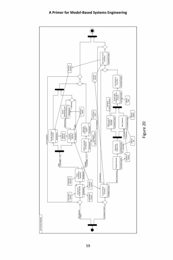
A Primer for Model-Based Systems Engineering
59
Figu
re 2
0
[Work
station]
<<
kill>
>
[Faile
d]
{ pro
bability
= 0
.1 }
[OK]
{ pro
bability
= 0
.9 }
[OK]
[Defici
enci
es]
<<
optional>
>
[# o
f re
quest
s]
[Com
mand C
ente
r]
[Not
In I
nvento
ry]
<<
optional>
>
<<
optional>
>
<<
optional>
>
[In I
nvento
ry]
[# o
f re
quest
s]
Acc
ept
And
Form
at
Request
Work
station
Check
Cert
ific
ation
Resp
onse
Work
station
Pro
vid
e P
roduct
To C
ust
om
er
Work
station
Evalu
ate
Pro
duct
s vs.
Request
Work
station
Report
Defici
enci
es
And
Reco
mm
endations
Work
station
Notify
Cust
om
er
of
Reje
ctio
n
Work
station
Genera
tePerf
orm
ance
Report
Work
station
Check
Pro
duct
Invento
ry
Com
mand C
ente
r
Prioritize
Request
Com
mand C
ente
r
Dete
rmin
eC
olle
ctor
Mix
Com
mand C
ente
r
Notify
Use
r O
fEst
imate
dSch
edule
Com
mand C
ente
r
Task
Colle
ctors
Com
mand C
ente
r
Acc
ept
And
Form
at
Colle
ctor
Pro
duct
s
Com
mand C
ente
r
Put
Pro
duct
In
Invento
ry
Com
mand C
ente
r
Get
Pro
duct
Fro
mIn
vento
ry
Com
mand C
ente
r
form
att
ed
request
cert
ific
ation
request
info
rmation
request
colle
ctio
npro
duct
s
invento
rypro
duct
defici
ency
report
cert
ific
ation
reje
ctio
n n
otifica
tion
cert
ific
ation
report
cert
ific
ation
resp
onse
priority
of
request
colle
ctor
mix
est
imate
ddeliv
ery
sch
edule
colle
ctor
task
ing
colle
ctor
data
invento
ryre
quest
act
Pro
cess
Request
s
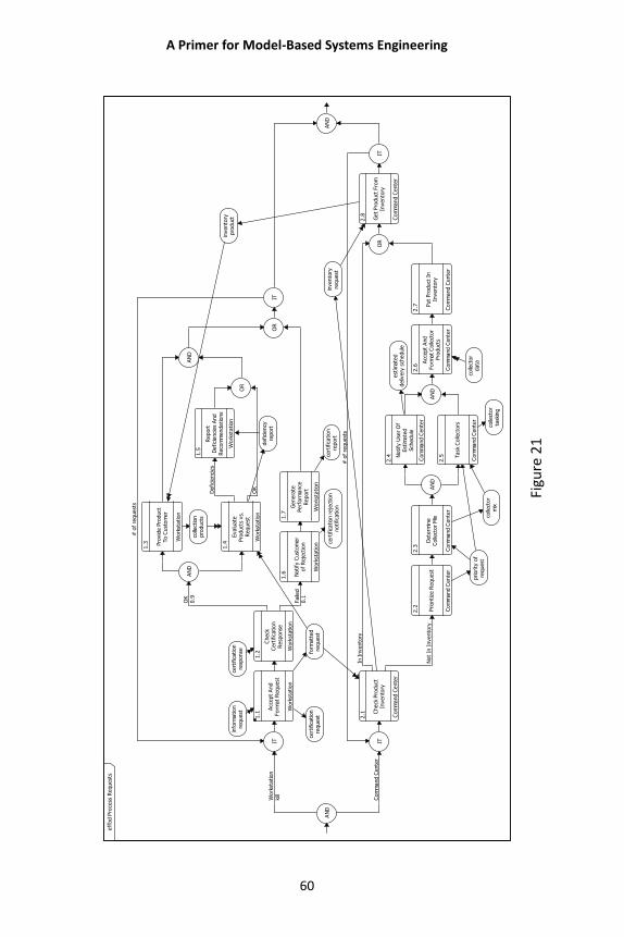
A Primer for Model-Based Systems Engineering
60
Figu
re 2
1
Com
mand C
ente
r
Not
In I
nvento
ry
In I
nvento
ry
# o
f re
quest
s
Work
station
kill
Faile
d0.1
OK
0.9
OK
Defici
enci
es
# o
f re
quest
s
AN
D
IT
1.1
Acc
ept
And
Form
at
Request
Work
station
1.2
Check
Cert
ific
ation
Resp
onse
Work
station
AN
D
1.3 Pro
vid
e P
roduct
To C
ust
om
er
Work
station
1.4
Evalu
ate
Pro
duct
s vs.
Request
Work
station
1.5
Report
Defici
enci
es
And
Reco
mm
endations
Work
station
OR
AN
D
1.6 Notify
Cust
om
er
of
Reje
ctio
n
Work
station
1.7
Genera
tePerf
orm
ance
Report
Work
station
OR
IT
IT
2.1 C
heck
Pro
duct
Invento
ry
Com
mand C
ente
r
2.2 Prioritize
Request
Com
mand C
ente
r
2.3
Dete
rmin
eC
olle
ctor
Mix
Com
mand C
ente
r
AN
D
2.4 N
otify
Use
r O
fEst
imate
dSch
edule
Com
mand C
ente
r
2.5 T
ask
Colle
ctors
Com
mand C
ente
r
AN
D
2.6
Acc
ept
And
Form
at
Colle
ctor
Pro
duct
s
Com
mand C
ente
r
2.7 P
ut
Pro
duct
In
Invento
ry
Com
mand C
ente
r
OR
2.8 Get
Pro
duct
Fro
mIn
vento
ry
Com
mand C
ente
r
IT
AN
D
form
att
ed
request
cert
ific
ation
request
info
rmation
request
colle
ctio
npro
duct
s
invento
rypro
duct
defici
ency
report
cert
ific
ation r
eje
ctio
nnotifica
tion
cert
ific
ation
report
cert
ific
ation
resp
onse
priority
of
request
colle
ctor
mix
est
imate
ddeliv
ery
sch
edule
colle
ctor
task
ing
colle
ctor
data
invento
ryre
quest
eff
bd P
roce
ss R
equest
s
A Primer for Model-Based Systems Engineering
61
Another important property of both the enhanced and
functional flow block diagrams is that time is a component of
the view. Each function has a duration and the input and
output items are the primary observables. Therefore, their
sequencing in time may be seen using the model repository’s
discrete event simulator.
Because the functions in an enhanced or functional flow block
diagram are the decomposition of a higher-level function, they
may also be represented by a functional hierarchy diagram.
Figure 22 (page 62) shows the functional hierarchy for the
behavior diagrams shown in the diagrams above. The
hierarchy diagram shows the depth of the functional
structure, starting from a source function for the hierarchy. In
addition, by selecting from a set of valid relationships for the
class of the starting entity, a hierarchy diagram reveals the
relationship paths and depth of the model for the selected
relationship set. This diagram is helpful for revealing
unfinished portions of the model as well as any miswiring of
the model.
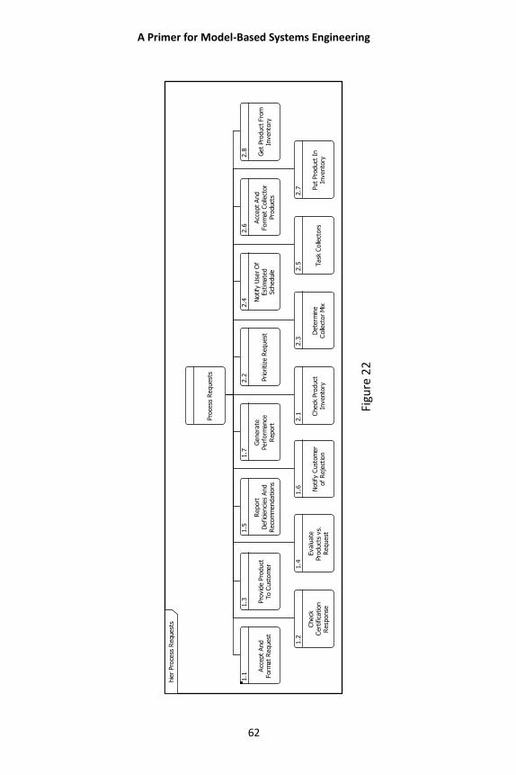
A Primer for Model-Based Systems Engineering
62
Figu
re 2
2
Pro
cess
Request
s
1.1
Acc
ept
And
Form
at
Request
1.2
Check
Cert
ific
ation
Resp
onse
1.3 Pro
vid
e P
roduct
To C
ust
om
er 1.4
Evalu
ate
Pro
duct
s vs.
Request
1.5
Report
Defici
enci
es
And
Reco
mm
endations
1.6 Notify
Cust
om
er
of
Reje
ctio
n1.7
Genera
tePerf
orm
ance
Report
2.1 C
heck
Pro
duct
Invento
ry
2.2 Prioritize
Request
2.3
Dete
rmin
eC
olle
ctor
Mix2
.4 Notify
Use
r O
fEst
imate
dSch
edule
2.5 T
ask
Colle
ctors2.6
Acc
ept
And
Form
at
Colle
ctor
Pro
duct
s 2.7 P
ut
Pro
duct
In
Invento
ry
2.8 Get
Pro
duct
Fro
mIn
vento
ry
hie
r Pro
cess
Request
s
A Primer for Model-Based Systems Engineering
63
Another diagram helpful for analysis in both the
functional/behavior and architecture/synthesis domains is the
N2 (N-squared) Diagram. The N2 diagram simply places the
functions of a behavior diagram along the principal diagonal
and the respective inputs/triggers and outputs in the off-
diagonal cells. Figure 23 (page 64) shows an N2 diagram.
Horizontally oriented line segments between functions and
items represent outputs, and vertically directed line segments
between functions and items represent inputs or triggers. Any
items appearing in the top row of the diagram represent items
arising from an external function or functions.
Correspondingly, any items appearing in the far-right column
represent outputs going to external functions. Two aspects of
this diagram are of interest to the engineering team. The first
is that time is not considered, and the second is that
functional interfaces are discerned. This diagram emphasizes
data and provides insight into allocation and interfaces.
The use of a model provides a disciplined framework in which
to construct the system. This is the case in the architectural
domain as well. Just as behavior is described and represented
graphically, so is physical architecture.
By looking at the model, the engineering team can “see”
behaviors and architectures and test them against the system
requirements. Although the various representations are
powerful tools for understanding and communicating the
model, they are not the model itself. They act as filters and
containers for the information that the model embodies. But it
is the language, structure, presentation, and argument that
combine to make the model the tool of choice in the field of
system design.
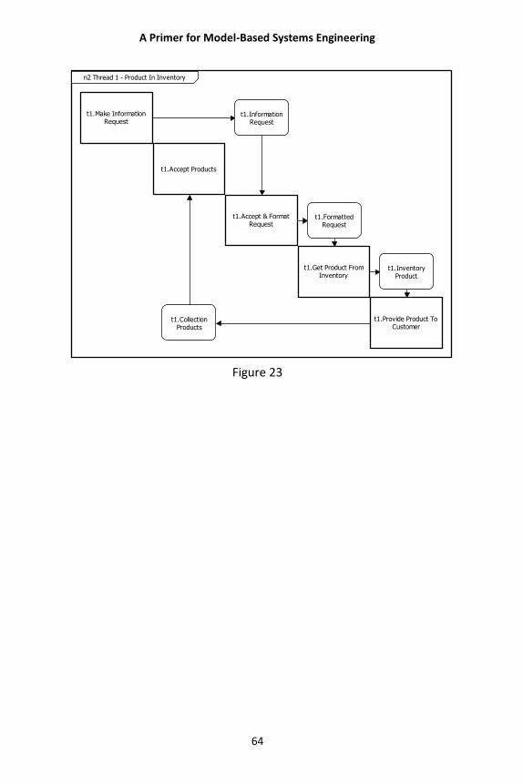
A Primer for Model-Based Systems Engineering
64
t1.Make InformationRequest
t1.Accept Products
t1.CollectionProducts
t1.InformationRequest
t1.Accept & FormatRequest
t1.FormattedRequest
t1.Get Product FromInventory
t1.InventoryProduct
t1.Provide Product ToCustomer
n2 Thread 1 - Product In Inventory
Figure 23
A Primer for Model-Based Systems Engineering
65
WHAT IS MODEL-BASED SYSTEMS
ENGINEERING?
Model-based systems engineering (MBSE) is fundamentally a
thought process. It provides the framework to allow the
systems engineering team to be effective and consistent right
from the start of any project. At the same time, it is flexible
enough to allow the “thought” process to adapt to special
constraints or circumstances present in the problem.
There are major advantages arising from using models as the
basis of systems engineering. Models thoroughly consider the
entire engineering problem, use a consistent language to
describe the problem and the solution, produce a coherently
designed solution, and comprehensively and verifiably answer
all the system requirements posed by the problem. These
traits of model-based systems engineering are significant
advantages when seeking a solution to the systems design
problem at hand.
The MBSE approach that is the subject of this primer is based
on a “layered” process of analyzing and solving systems design
problems. Developed by Jim Long, Marge Dyer, and Mack
Alford, along with a succession of colleagues and associates, it
has developed in a way that has now been named STRATA™
by Vitech Corporation. The name calls out the central principle
of the method—Strategic Layers—because the method is built
around handling the problem in layers of increasing
granularity in order to converge strategically on the solution.
Beginning at the highest, most general level, the problem
statement (system-level requirements set) is analyzed and
translated into functional behaviors that the system must
perform to fulfill the requirements. These behaviors are
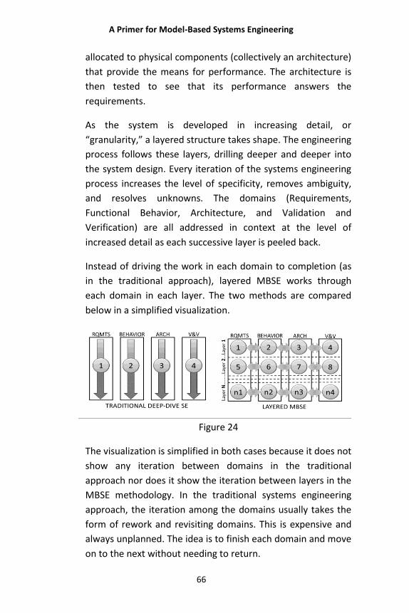
A Primer for Model-Based Systems Engineering
66
allocated to physical components (collectively an architecture)
that provide the means for performance. The architecture is
then tested to see that its performance answers the
requirements.
As the system is developed in increasing detail, or
“granularity,” a layered structure takes shape. The engineering
process follows these layers, drilling deeper and deeper into
the system design. Every iteration of the systems engineering
process increases the level of specificity, removes ambiguity,
and resolves unknowns. The domains (Requirements,
Functional Behavior, Architecture, and Validation and
Verification) are all addressed in context at the level of
increased detail as each successive layer is peeled back.
Instead of driving the work in each domain to completion (as
in the traditional approach), layered MBSE works through
each domain in each layer. The two methods are compared
below in a simplified visualization.
Figure 24
The visualization is simplified in both cases because it does not
show any iteration between domains in the traditional
approach nor does it show the iteration between layers in the
MBSE methodology. In the traditional systems engineering
approach, the iteration among the domains usually takes the
form of rework and revisiting domains. This is expensive and
always unplanned. The idea is to finish each domain and move
on to the next without needing to return.
A Primer for Model-Based Systems Engineering
67
In MBSE the iteration can be confined to an adjacent layer and
is easily achieved without interfering with the intended design
progress. This represents a huge advantage over the
traditional approach. Revisiting the domains often means
restarting the design process (or a significant portion of it) in
order to account for the changes made in that domain during
the revisit. This causes reopening the design and reworking
areas that have already been covered. None of that is
necessary with the planned and incremental iterations that
are part of the workflow in the layered MBSE method.
The layer-by-layer approach of MBSE assures that the domains
are considered in context. One of the critical system design
mistakes is losing the system context. This happens as a
natural outgrowth of thinking about the design analytically—
that is, by tearing it apart into its components and focusing at
that level. The work of the late Russell Ackoff, a University of
Pennsylvania business professor and pioneering “systems
thinker,” reminds us that we must also think “synthetically,”
holding the entire system in view and considering it as a
whole. Because a system is, at its root, more than the simple
sum of its parts, we cannot afford to lose the systems view or
we lose the essence of the system itself. (See, e.g., R. Ackoff
with H. Addison and A. Carey, Systems Thinking for Curious
Managers, Triarchy Press, 2010.)
Approaches that involve “deep dives” into one area (e.g.,
requirements) run the substantial risk of obscuring the
systemic risks incurred when the complex relationships
between domains are not fully considered. The central power
of the MBSE approach lies in its careful and complete
consideration of the system design in an orderly and
systematic fashion. This can happen only through the orderly
process and excellent communication which must be the
hallmarks of an effective systems engineering process.
A Primer for Model-Based Systems Engineering
68
This approach to solving the problem in layers is the heart of
MBSE. With this approach (addressing all domains in each
layer), there comes an assurance that all aspects of the
engineering problem at hand are addressed completely and
consistently. The layers and their interrelationships also
provide a solution that can be easily verified and validated
against the needs that created the problem. By stripping away
the layers as we might “peel an onion,” we can be assured
that we have indeed addressed the problem in a meaningful
and productive way.
As the layers are peeled away, the process converges on the
solution. The discipline and rigor of the MBSE process assure
that, like the peeled onion, the design never finds that the
next layer is larger than the last. The process instead
converges on the solution naturally as a product of the MBSE
process.
Requirements for a Systems Engineering
Process
In order for such a solution-seeking process to be effective, it
must satisfy some fundamental requirements. MBSE answers
these requirements quite well.
Requirement 1: The process must consistently lead to the development of successful systems. MBSE is a coherent and comprehensive means of consistently
arriving at a realizable system effectively and efficiently. By
engineering the system horizontally in layers and completing
all the systems engineering activities at one layer before
decomposing/elaborating in the next layer, the MBSE
engineering team advances the design from layer to layer. In
A Primer for Model-Based Systems Engineering
69
this way, MBSE converges layer by layer on a system solution
that successfully meets the needs behind the development
process.
As the work progresses through the layers, the engineering
activities performed in each domain change emphases. In
layer 1, work focuses on the requirements domain along with
verification and validation, if done properly. Work in layer 2
emphasizes the functional/behavior domain. Succeeding
layers are a balance between the functional/behavior and
architecture/synthesis domains. Refinements in system
control, error handling, and resource management are added
at each succeeding layer.
Preliminary specifications are available at the conclusion of
each layer’s activities. Therefore, the MBSE modeling process
yields meaningful draft specifications throughout
development, a distinct advantage over conventional
approaches. Doing systems engineering in layers makes the
MBSE process virtually fail-safe. Should external constraints
force the process to stop at any given layer, the draft solution
is complete to the level of the last layer finished.
A convergent process like STRATA uses this disciplined,
ordered process to make the best choices under the given
conditions. This is not to say that any particular decision is not
flawed. But where flaws exist, any correction of them can
occur without dire programmatic consequences. In addition,
by framing and developing the solutions in layers, STRATA
ensures that assumptions, boundaries, interfaces, functions,
and architectures are convergent, consistent, and complete.
The convergent process is the means of avoiding catastrophic
rework and an unlimited cycle of fixing flaws. With MBSE, the
means of resolving issues is not unduly costly or time
consuming. This is because measures exist to allow the
A Primer for Model-Based Systems Engineering
70
systems engineering team to know when each design stage is
complete, to see the direction for design advancement, to
manage the impacts around resolving flaws, and to mitigate
the consequences of uncovered design issues.
Requirement 2: The process must manage system complexity well. As problems and their solutions become more complex, it is
correspondingly more difficult to ensure that solutions are
consistently and completely defined. Applying MBSE principles
as an engineering and management process approach
provides a powerful way of describing problems and their
solutions. Because this description process is rigorous and
complete, systems engineers are able to manage the problem
complexity in a complete and disciplined manner.
As will be shown below, the integrated nature of the layered
model is the key to managing complexity. It “automates” the
tracking of the relationships and tracing paths that would
otherwise need to be maintained and followed by hand. What
would, absent the model’s integrated structure, be an arduous
task of ferreting out the information from multiple sources
becomes the simple task of looking to the model, where the
information has already been entered and maintained over
time. Freed from the ministerial task of repetitively finding
and recording information from a variety of repositories, the
design team is enabled to leverage the power of the MBSE
model to manage levels of complexity simply not possible with
more fragmented and labor-driven approaches.
A Primer for Model-Based Systems Engineering
71
Requirement 3: The process must lead to effective solutions to a broad range of customer needs. The MBSE approach provides a process that converges on a
complete solution across a broad range of customer needs.
MBSE is adaptable to the particular engineering problem type
at hand, and the process advances the system design without
performance disruption—even in the midst of unknowns.
Engineering, operational, and social choices can be considered
in advancing the design. In addition, the system can include
the ability to have a nondisruptive means of accommodating
on-going source requirement changes.
Requirement 4: The process must accommodate the three main problem classes (engineering unprecedented systems, reverse engineering, and middle-out engineering). Because it is adaptable to the layers it finds in the problem
definition, MBSE is useful in situations that require top-down
engineering, reverse engineering, and middle-out engineering.
In each instance, the engineering process begins where the
needs exist and moves through the layers of the problem to
the ultimate solution. Once the ultimate solution is reached, it
is necessary to “prove” that the solution addresses the needs
that drove the development project. MBSE makes this process
manageable by proceeding through and documenting the
development project in a way that is conducive to tracing the
sufficiency of the system offered as a solution.
STRATA iterates through the primary concurrent systems
engineering activities at each layer. The degree of effort within
each domain varies according to the nature of the problem,
the level being worked, and the boundary conditions affecting
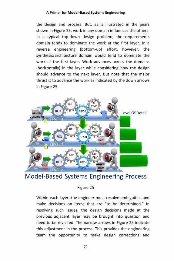
A Primer for Model-Based Systems Engineering
72
the design and process. But, as is illustrated in the gears
shown in Figure 25, work in any domain influences the others.
In a typical top-down design problem, the requirements
domain tends to dominate the work at the first layer. In a
reverse engineering (bottom-up) effort, however, the
synthesis/architecture domain would tend to dominate the
work at the first layer. Work advances across the domains
(horizontally) in the layer while considering how the design
should advance to the next layer. But note that the major
thrust is to advance the work as indicated by the down arrows
in Figure 25.
Figure 25
Within each layer, the engineer must resolve ambiguities and
make decisions on items that are “to be determined.” In
resolving such issues, the design decisions made at the
previous adjacent layer may be brought into question and
need to be revisited. The narrow arrows in Figure 25 indicate
this adjustment in the process. This provides the engineering
team the opportunity to make design corrections and
A Primer for Model-Based Systems Engineering
73
refinements as a result of new insights, discoveries, or design
decisions.
A key STRATA concept is that the engineering team should
only have to iterate between adjacent layers. This allows the
process to converge on a solution. Completeness and
convergence are essential principles of STRATA. Therefore, a
layer should be completed before advancing to the next layer
(preserving completeness), and iteration back more than one
layer becomes unnecessary. Should something be introduced
into the problem (e.g., an external change) that necessitates
revisiting earlier layers, the engineering team would be
alerted to the creation of a major problem involving schedule
and cost impacts resulting from having to reengineer the
solution back through the layers to reach the point of process
progress at which the issue arises.
Because it converges on the ultimate solution layer by layer,
STRATA is truly a convergent process. This leads to it being
“fail-safe.” A truly convergent process always leads to a
solution for any problem set that has a realizable solution,
even given the constraints of cost and schedule. However, if
circumstances (such as a redirection of resources) disrupt the
process, the convergent process produces a draft system and
other specifications at whatever process layer it encounters
the disruption. This means that an abbreviated process does
not result in a complete waste of the effort invested up to the
time of interruption. The solution at that point is complete to
the level of granularity represented in the last layer
completed.
The system design process proceeds from a conceptual to a
detailed description by moving downward with increasing
detail or granularity from one layer to the next. Each of the
iterations analyzes a layer within the system design process.
Beginning with the basic, high-level user requirements serves
A Primer for Model-Based Systems Engineering
74
to define broad system characteristics and objectives. Clarity is
brought to these high-level expressions until the process has
defined the system to a point of sufficient granularity to allow
the system’s physical implementation to begin.
Most systems engineering processes are not convergent
precisely because they have difficulty managing process
interdependencies and consistency across engineering
domains under the constraints of satisfying cost and schedule.
In those approaches, these factors tend to be treated
disjointedly. By contrast, the STRATA approach enhances the
project discipline by proceeding layer by layer across all
domains, causing all factors to be addressed both
systematically and systemically. The engineering team and
project management, therefore, have better insight into the
trade-offs needed to advance the design effort. This allows the
domains to advance together, preserving completeness.
In addition, the engineering team can work consistently at the
correct level within the design process. There are some
necessary exceptions, such as risk reduction and addressing
long-lead issues. For these issues, deep-dive studies are
appropriate to ensure system success. Ultimately, however,
the complete solution unfolds in increasing levels of detail and
intermediary results are available for early review and
validation.
MBSE Model and System Definition Language
Whether based on MBSE or not, all system design efforts
develop their own language over time because of the
necessity to communicate certain ideas clearly. The problem is
that these ad hoc approaches rarely achieve the fundamental
goals of clear communication. They take time to develop and,
because the development is unplanned and ad hoc, this
A Primer for Model-Based Systems Engineering
75
impedes system design progress while the language is
established. MBSE avoids this situation because the language
is developed in advance and eliminates confusion from the
project’s start.
The engineer uses a formal specification language to
characterize the various design entities (requirements,
functions, components, etc.) in a repository. Using this
language and a repository allows the engineer to construct a
systems “model.” By capturing all the system information in
the repository and correcting all errors, the engineer builds
the repository to contain the system model from which the
design team will produce the system, segment, and interface
specifications.
Using the language constructs of the system definition
language, the systems engineer can develop a model that
illuminates both the physical architecture and the functional
behavior of the system. The functions and the interactions of
the system with the external entities enable the system to
process the inputs into the outputs needed to satisfy the
needs that drive the system. This discussion of the MBSE
process now turns to the concepts of system function and
behavior, and the development of system threads. Threads
are sequences of behavior that trace defined paths through
the system. Collectively these threads integrate to define the
system behavior.
There are substantial benefits to maintaining system models
throughout the system life cycle. In the development stage,
the development team must characterize the system problem.
This is an effort to define both the system context
representation and the system boundary. The system
boundary definition specifies the system of interest, as well as
all external entities interfacing with the system. Thus, the
A Primer for Model-Based Systems Engineering
76
development team identifies the system-level functional
interfaces between the system and those external entities.
When working with top-down problems, the engineering team
draws from the source documents (requirements, concept of
operations, and other documentation) to identify what the
system is and what it does at its most abstract level. This
functional context model consists of the “root function” for
the system and corresponding root functions for each of the
external entities encountered. Thus, this diagram identifies all
system-level stimuli and responses for the system.
The system boundary also identifies the limits of system
development. The engineering team is responsible for
everything within the boundary, handling all inputs, and
developing all system outputs. In addition, they must manage
all the system interfaces with external systems. Even though
this high-level process appears overly simple, its purpose is to
identify the principal inputs and outputs transiting the system
boundary and to discover whether any external systems are
missing. In many cases, this activity is not done at all or not
done well.
With the originating requirements in hand, the engineer
proceeds to layer 1.
Developing Layer 1 of Our Solution
Layer 1: Requirements Work in the requirements domain begins at the highest level
with relatively general statements from the system owners
and stakeholders. These may take the form of a Concept of
Operations (CONOPS), a Request for Proposal (RFP), internal
customer documents, or all of these and more. From these
A Primer for Model-Based Systems Engineering
77
descriptions of the system and its purpose, the requirements
will begin to emerge.
As the design progresses through the layers, the requirements
will be interpreted and refined into more and more particular
statements. The more particular requirements are the
“children” of their more general “parent” requirements.
Take, for example, the requirement in the sample problem
that the system “accept information requests from certified
customers.” As the design proceeds, it becomes apparent that
customers need to be able to make requests for images in
several different media/formats. For instance, they need to be
able to make a verbal request by phone. The system must be
able to accept and process such a request. The initial
requirement for accepting customer requests (the parent) is
refined by the more specific requirement that the system
“accept requests via telephone” (the child).
Layer 1: Functional Behavior Once the requirements have been collected and analyzed at
the level of the current layer, the next step in the design
process is to design the functional behavior to implement the
requirements. Like the other domains, the behavioral (logical)
design advances in layers from the more abstract toward the
more specific and complete functional representations. This is
done concurrently with corresponding efforts in the
requirements domain and the architecture/synthesis domain.
The model interrelationships among these domains must be
maintained to ensure completeness and convergence. This
also minimizes the likelihood of having major rework because
of decisions made at an inappropriate level in another
domain.
A Primer for Model-Based Systems Engineering
78
Concurrently, an analysis of input/output transactions occurs
in the requirements domain and in the architecture/synthesis
domain to characterize broad classes of input/output
transactions based upon the system boundary determinations
that have been made. This identifies the stimulus-response
characteristics of the system. The objective is to derive the
possible threads to analyze in layer 2, which is a discovery
process. System threads are generated for several reasons:
1. To make sure that every system input (stimulus) is
properly addressed.
2. To assure that the system logic is fully developed.
3. To break the problem into solvable pieces.
In particular, the processing required for each class of system
stimulus/input should identify a thread. This also enables the
design team to identify system-level functions. Some of the
questions addressed in this discovery process are:
1. Which inputs or input sequences lead to which outputs or
output sequences?
2. Are there outputs or output sequences for which there is
not an external input (stimulus)?
3. Are there inputs or input sequences for which there are
not external outputs (responses)?
When the source documents lack sufficient information to
determine these threads, the engineering team may suggest
possible stimulus-response possibilities and engage the
customer in approving these or identifying additional threads.
The work products within the functional/behavior domain are
sometimes collectively referred to as the “functional
architecture” of the system.
A Primer for Model-Based Systems Engineering
79
Layer 1: Architecture Source documents serve to define the top-level architecture
and functional context. Its purpose is to assure the
identification of all the externals and environmental entities.
Thereafter, the context aids in discovering all the principal
input and output classes transiting the system boundary. This
identifies the primary system-level interfaces. Each layer
advances the completeness of the design and influences the
work in the other domains. Conversely, the work in the other
domains influences the physicality of each layer. Handling this
interdependence is foundational for finding balance in the
system design. MBSE does this in a disciplined, orderly
fashion.
Just as the functional/behavior domain is a part of each layer
of the STRATA, so is the architecture/synthesis domain.
Developed in concert with the analytical work on the
requirements domain, it is influenced by allocation decisions
made in the behavioral domain. The objectives of the
architectural model are determined by the current level of the
system model. For example, layer 1 architectural model
objectives are to identify the system and the external
counterparts with which it must interact. Accordingly, layer 2
architectural model objectives seek to discover physical
partitioning strategies for the system. Subsequent layer-by-
layer objectives investigate, refine, and evaluate the strengths
and weaknesses of each partitioning strategy employed. They
seek to maintain the relationships among all the other
domains—preserving each layer’s boundary conditions and
maintaining the evidentiary path for system acceptance.
Architectural Language There is a clear need for a language to express the system’s
architectural design. The language of architecture/synthesis is
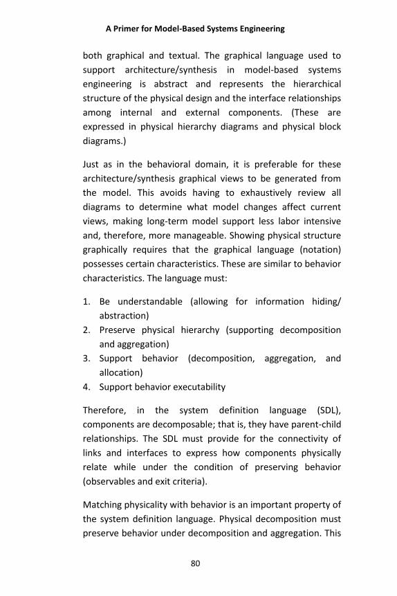
A Primer for Model-Based Systems Engineering
80
both graphical and textual. The graphical language used to
support architecture/synthesis in model-based systems
engineering is abstract and represents the hierarchical
structure of the physical design and the interface relationships
among internal and external components. (These are
expressed in physical hierarchy diagrams and physical block
diagrams.)
Just as in the behavioral domain, it is preferable for these
architecture/synthesis graphical views to be generated from
the model. This avoids having to exhaustively review all
diagrams to determine what model changes affect current
views, making long-term model support less labor intensive
and, therefore, more manageable. Showing physical structure
graphically requires that the graphical language (notation)
possesses certain characteristics. These are similar to behavior
characteristics. The language must:
1. Be understandable (allowing for information hiding/
abstraction)
2. Preserve physical hierarchy (supporting decomposition
and aggregation)
3. Support behavior (decomposition, aggregation, and
allocation)
4. Support behavior executability
Therefore, in the system definition language (SDL),
components are decomposable; that is, they have parent-child
relationships. The SDL must provide for the connectivity of
links and interfaces to express how components physically
relate while under the condition of preserving behavior
(observables and exit criteria).
Matching physicality with behavior is an important property of
the system definition language. Physical decomposition must
preserve behavior under decomposition and aggregation. This
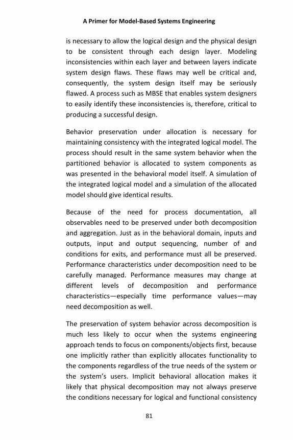
A Primer for Model-Based Systems Engineering
81
is necessary to allow the logical design and the physical design
to be consistent through each design layer. Modeling
inconsistencies within each layer and between layers indicate
system design flaws. These flaws may well be critical and,
consequently, the system design itself may be seriously
flawed. A process such as MBSE that enables system designers
to easily identify these inconsistencies is, therefore, critical to
producing a successful design.
Behavior preservation under allocation is necessary for
maintaining consistency with the integrated logical model. The
process should result in the same system behavior when the
partitioned behavior is allocated to system components as
was presented in the behavioral model itself. A simulation of
the integrated logical model and a simulation of the allocated
model should give identical results.
Because of the need for process documentation, all
observables need to be preserved under both decomposition
and aggregation. Just as in the behavioral domain, inputs and
outputs, input and output sequencing, number of and
conditions for exits, and performance must all be preserved.
Performance characteristics under decomposition need to be
carefully managed. Performance measures may change at
different levels of decomposition and performance
characteristics—especially time performance values—may
need decomposition as well.
The preservation of system behavior across decomposition is
much less likely to occur when the systems engineering
approach tends to focus on components/objects first, because
one implicitly rather than explicitly allocates functionality to
the components regardless of the true needs of the system or
the system’s users. Implicit behavioral allocation makes it
likely that physical decomposition may not always preserve
the conditions necessary for logical and functional consistency
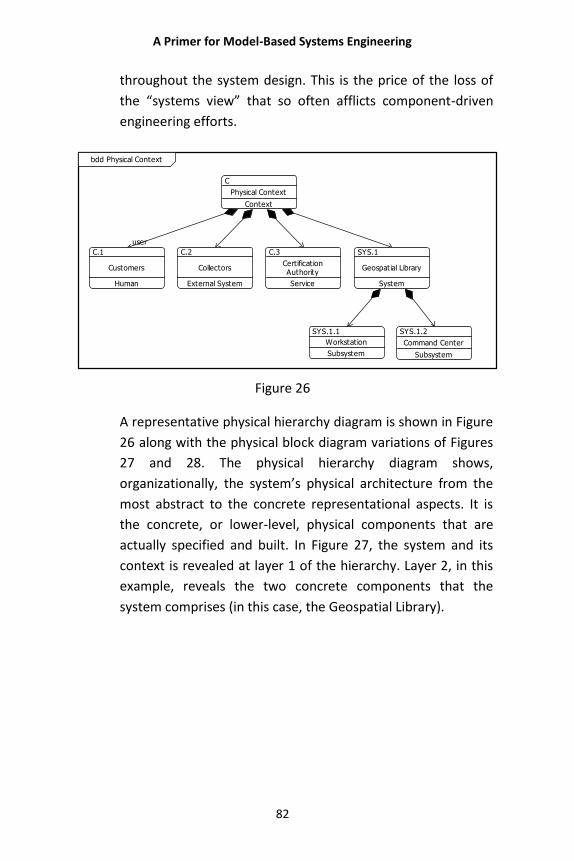
A Primer for Model-Based Systems Engineering
82
throughout the system design. This is the price of the loss of
the “systems view” that so often afflicts component-driven
engineering efforts.
user
C
Physical Context
Context
C.1
Customers
Human
C.2
Collectors
External System
C.3
CertificationAuthority
Service
SYS.1
Geospatial Library
System
SYS.1.1
Workstation
Subsystem
SYS.1.2
Command Center
Subsystem
bdd Physical Context
Figure 26
A representative physical hierarchy diagram is shown in Figure
26 along with the physical block diagram variations of Figures
27 and 28. The physical hierarchy diagram shows,
organizationally, the system’s physical architecture from the
most abstract to the concrete representational aspects. It is
the concrete, or lower-level, physical components that are
actually specified and built. In Figure 27, the system and its
context is revealed at layer 1 of the hierarchy. Layer 2, in this
example, reveals the two concrete components that the
system comprises (in this case, the Geospatial Library).
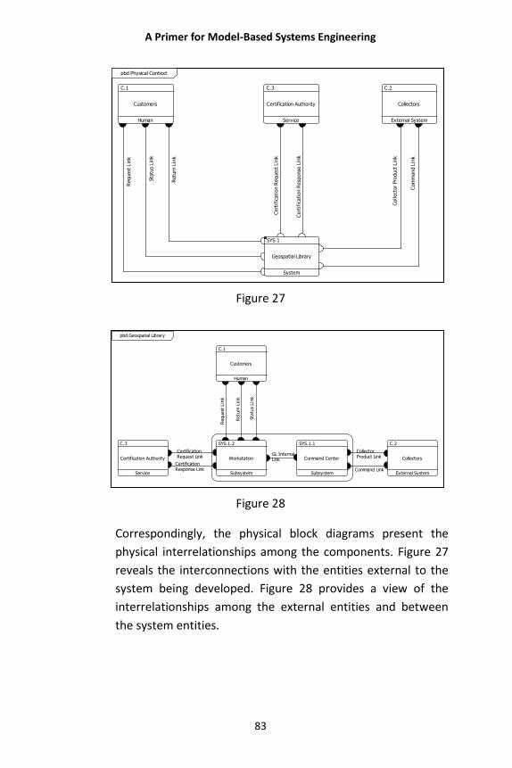
A Primer for Model-Based Systems Engineering
83
Com
mand L
ink
Cert
ific
ati
on R
esp
onse
Lin
k
Request
Lin
k
Cert
ific
ati
on R
equest
Lin
k
Retu
rn L
ink
Sta
tus
Lin
k
Collect
or
Pro
duct
Lin
k
C.1
Customers
Human
C.2
Collectors
External System
C.3
Certification Authority
Service
SYS.1
Geospatial Library
System
pbd Physical Context
Figure 27
CertificationResponse Link
GL InternalLink
Command Link
CollectorProduct Link
Sta
tus
Lin
k
CertificationRequest Link
Retu
rn L
ink
Request
Lin
k
SYS.1.1
Command Center
Subsystem
SYS.1.2
Workstation
Subsystem
C.1
Customers
Human
C.2
Collectors
External System
C.3
Certification Authority
Service
pbd Geospatial Library
Figure 28
Correspondingly, the physical block diagrams present the
physical interrelationships among the components. Figure 27
reveals the interconnections with the entities external to the
system being developed. Figure 28 provides a view of the
interrelationships among the external entities and between
the system entities.
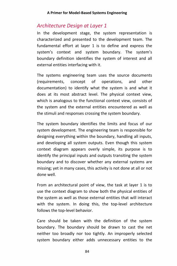
A Primer for Model-Based Systems Engineering
84
Architecture Design at Layer 1 In the development stage, the system representation is
characterized and presented to the development team. The
fundamental effort at layer 1 is to define and express the
system’s context and system boundary. The system’s
boundary definition identifies the system of interest and all
external entities interfacing with it.
The systems engineering team uses the source documents
(requirements, concept of operations, and other
documentation) to identify what the system is and what it
does at its most abstract level. The physical context view,
which is analogous to the functional context view, consists of
the system and the external entities encountered as well as
the stimuli and responses crossing the system boundary.
The system boundary identifies the limits and focus of our
system development. The engineering team is responsible for
designing everything within the boundary, handling all inputs,
and developing all system outputs. Even though this system
context diagram appears overly simple, its purpose is to
identify the principal inputs and outputs transiting the system
boundary and to discover whether any external systems are
missing; yet in many cases, this activity is not done at all or not
done well.
From an architectural point of view, the task at layer 1 is to
use the context diagram to show both the physical entities of
the system as well as those external entities that will interact
with the system. In doing this, the top-level architecture
follows the top-level behavior.
Care should be taken with the definition of the system
boundary. The boundary should be drawn to cast the net
neither too broadly nor too tightly. An improperly selected
system boundary either adds unnecessary entities to the
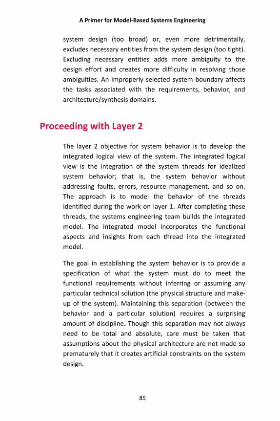
A Primer for Model-Based Systems Engineering
85
system design (too broad) or, even more detrimentally,
excludes necessary entities from the system design (too tight).
Excluding necessary entities adds more ambiguity to the
design effort and creates more difficulty in resolving those
ambiguities. An improperly selected system boundary affects
the tasks associated with the requirements, behavior, and
architecture/synthesis domains.
Proceeding with Layer 2
The layer 2 objective for system behavior is to develop the
integrated logical view of the system. The integrated logical
view is the integration of the system threads for idealized
system behavior; that is, the system behavior without
addressing faults, errors, resource management, and so on.
The approach is to model the behavior of the threads
identified during the work on layer 1. After completing these
threads, the systems engineering team builds the integrated
model. The integrated model incorporates the functional
aspects and insights from each thread into the integrated
model.
The goal in establishing the system behavior is to provide a
specification of what the system must do to meet the
functional requirements without inferring or assuming any
particular technical solution (the physical structure and make-
up of the system). Maintaining this separation (between the
behavior and a particular solution) requires a surprising
amount of discipline. Though this separation may not always
need to be total and absolute, care must be taken that
assumptions about the physical architecture are not made so
prematurely that it creates artificial constraints on the system
design.
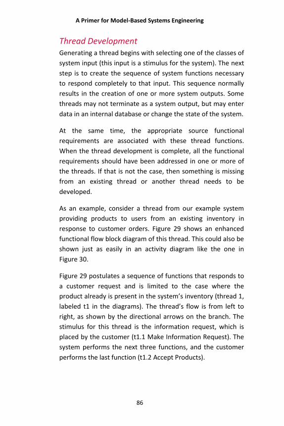
A Primer for Model-Based Systems Engineering
86
Thread Development Generating a thread begins with selecting one of the classes of
system input (this input is a stimulus for the system). The next
step is to create the sequence of system functions necessary
to respond completely to that input. This sequence normally
results in the creation of one or more system outputs. Some
threads may not terminate as a system output, but may enter
data in an internal database or change the state of the system.
At the same time, the appropriate source functional
requirements are associated with these thread functions.
When the thread development is complete, all the functional
requirements should have been addressed in one or more of
the threads. If that is not the case, then something is missing
from an existing thread or another thread needs to be
developed.
As an example, consider a thread from our example system
providing products to users from an existing inventory in
response to customer orders. Figure 29 shows an enhanced
functional flow block diagram of this thread. This could also be
shown just as easily in an activity diagram like the one in
Figure 30.
Figure 29 postulates a sequence of functions that responds to
a customer request and is limited to the case where the
product already is present in the system’s inventory (thread 1,
labeled t1 in the diagrams). The thread’s flow is from left to
right, as shown by the directional arrows on the branch. The
stimulus for this thread is the information request, which is
placed by the customer (t1.1 Make Information Request). The
system performs the next three functions, and the customer
performs the last function (t1.2 Accept Products).
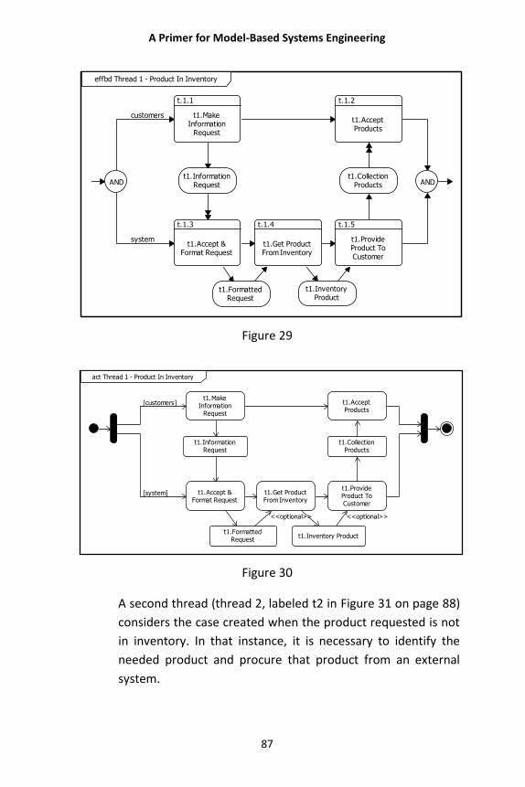
A Primer for Model-Based Systems Engineering
87
system
customers
AND
t.1.1
t1.MakeInformation
Request
t.1.2
t1.AcceptProducts
t.1.3
t1.Accept &Format Request
t.1.4
t1.Get ProductFrom Inventory
t.1.5
t1.ProvideProduct ToCustomer
ANDt1.Information
Requestt1.Collection
Products
t1.FormattedRequest
t1.InventoryProduct
effbd Thread 1 - Product In Inventory
Figure 29
[customers]
[system]
<<optional>> <<optional>>
t1.MakeInformation
Request
t1.AcceptProducts
t1.Accept &Format Request
t1.Get ProductFrom Inventory
t1.ProvideProduct ToCustomer
t1.InformationRequest
t1.CollectionProducts
t1.FormattedRequest
t1.Inventory Product
act Thread 1 - Product In Inventory
Figure 30
A second thread (thread 2, labeled t2 in Figure 31 on page 88)
considers the case created when the product requested is not
in inventory. In that instance, it is necessary to identify the
needed product and procure that product from an external
system.
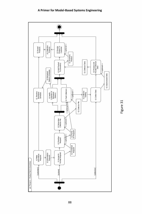
A Primer for Model-Based Systems Engineering
88
Figu
re 3
1
[cust
om
ers
]
[syst
em
]
<<
optional>
><
<optional>
>
<<
optional>
>
<<
optional>
><
<optional>
>
[colle
ctors
]
<<
optional>
>
t2.M
ake
Info
rmation
Request
t2.
Rece
ive
Est
imate
dSch
edule
t2.A
ccept
Pro
duct
s
t2.A
ccept
&Form
at
Request
t2.P
rioritize
Request
t2.D
ete
rmin
eC
olle
ctor
Mix
t2.N
otify
Cust
om
er
of
Est
imate
dD
eliv
ery
t2.T
ask
Colle
ctors
t2.A
dd P
roduct
To I
nvento
ry
t2.P
rovid
ePro
duct
To
Cust
om
er
t2.C
olle
ct D
ata
t2.P
roce
ss a
nd
Pro
vid
e C
olle
cted
Data
t2.I
nfo
rmation
Request
t2.E
stim
ate
dD
eliv
ery
Sch
edule
t2.C
olle
ctio
nPro
duct
s
t2.F
orm
att
ed
Request
t2.P
riority
Of
Request
t2.C
olle
ctor
Mix
t2.C
olle
ctor
Task
ing
t2.I
nvento
ryPro
duct
t2.C
olle
ctor
Data
t2.U
npro
cess
ed D
ata
act
Thre
ad 2
- P
roduct
Not
In I
nvento
ry
A Primer for Model-Based Systems Engineering
89
Figure 31 is more complex and shows logic that requires the
functional involvement of the system with two external
entities. The functions performed by the customer are on the
top branch and include making the initial request, receiving
the estimate regarding the anticipated delivery date for the
customer's order of products, and accepting the products on
delivery.
The functions performed by the collectors are on the bottom
branch and include collecting the data in response to the
tasking from the system, as well as processing and providing
the collected images back to the system for placement into
the system inventory. The system performs the remaining
functions.
These two threads cover the two possibilities that result when
a customer makes a request. Once the system accepts the
request, it either does or does not have the image in
inventory. If it does, the functional behavior follows thread
one and the image is retrieved and provided to the customer.
That case is covered by Thread 1. If the system inventory does
not include the requested image, the system must task a
collector to procure it, add the image to the inventory, and
provide the image to the customer. That case is represented
by Thread 2. Together, they represent the operation of the
Geospatial Library.
After generating the system threads for every class of system
input, it is necessary to check to see whether every system
output identified in either the system context diagram or the
system requirements has been addressed. If not, there must
be threads that have not yet been identified or outputs that
are the result of internal triggers (e.g., a requirement for
periodic system health and status data). These internal
triggers must be identified and threads generated for each
case. These threads form the basis for creating the integrated
A Primer for Model-Based Systems Engineering
90
logical model and should be saved for later reference to help,
for example, formulate system test threads.
Once the systems engineering team completes the system
threads, they develop the integrated logic to make the logical
model more compact and understandable, and to take
advantage of commonalities among the threads. At this point,
the logical model represents the system’s idealized behavior.
Subsequent work adds complexity to address error conditions,
resource management, failure recovery, security, and other
needs. Each layer advances the completeness of the design
and influences the work in the other domains. In the same
way, the work in the other domains influences the
functionality of each layer. Designing with this in mind is
fundamental to finding balance in the system design.
A Primer for Model-Based Systems Engineering
91
Thread Integration Once the set of system threads is complete, they must be
integrated and any commonality of functionality among them
accounted for. Systems engineers must also account for the
logical interaction and logical control for that combination of
threads.
It is tempting to integrate these threads by keeping them in
their original form and representing them in a multibranched
parallel construct. This strategy actually makes it difficult to
define and/or understand system function interactions as an
integrated whole. Rather than simply aggregating the threads
together, it is helpful to integrate their behaviors into a
synthetic whole.
The objective is to integrate the threads in a manner that
minimizes the size and complexity of the final integration. This
is done by minimizing the duplication of functions and logic
streams. The set of system threads identifies how the system
responds to each input independent of all other inputs. This is
an effective strategy for managing complexity. However, the
individual threads do not account for commonality of
functional process, nor do they account for thread
interactions.
One common integration problem is that different individuals
generate the different threads. That means that similar
functions may be described as having different names,
different boundaries, and different inputs and outputs. The
resolution of these differences must be a part of integrating
the threads into a single, common architecture.
While some differences are differences in name only, others
are functionally real. Functions with differing inputs and
outputs are actually different functions. Likewise, functions
A Primer for Model-Based Systems Engineering
92
with different exit conditions are different functions. This
must be taken into account when defining the unique system
functions during the integration of the threads.
The integration process defines the means of control over the
integrated whole. This activity may prove to be a challenge,
but it is essential in order to gain an efficient and
understandable set of system logic. It is usually easier to
integrate the threads by looking for common entities.
Examples might be inputs from the same external system,
inputs through the same input channel, or inputs requiring the
same initial functional processing. This integration activity is a
creative challenge dependent on the insight gained during
thread development, and there is no standard formula or
process for it.
The resulting integrated behavior diagram contains the
threads involved in the integration. Each of them can be seen
as an identifiable path. Figure 32 is an enhanced function flow
block diagram (EFFBD) resulting from the integration of the
individual threads into a single integrated behavior diagram.
This depicts the functional architecture of the system. It
consists of the structured sequences and logic of system
functions, including the inputs, outputs, and triggers which
relate to the functions. When integrated with the enhanced
EFFBD for all of the external systems, the resulting logical
model becomes executable.
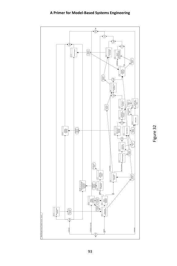
A Primer for Model-Based Systems Engineering
93
Figu
re 3
2
Colle
ctio
ns
Cust
om
ers
Syst
em
kill
OK
0.9
Not
In I
nvento
ry
In I
nvento
ry
OK
Defici
enci
es
Faile
d0.1
Cert
ific
ation A
uth
ority
AN
D
AN
D
C.1
.1
Make
Info
rmation
Request
C.1
.2
Rece
ive
Est
imate
dSch
edule
C.1
.3
Acc
ept
Pro
duct
s
C.1
.4
Rece
ive N
otifica
tion
of
Cust
om
er
of
Cert
ific
ation
Reje
ctio
n
AN
D
C.3
.1
Valid
ate
Cust
om
er
Cert
ific
ation
1.1
Acc
ept
And
Form
at
Request
1.2
Check
Cert
ific
ation
Resp
onse
1.6 Notify
Cust
om
er
of
Reje
ctio
n
1.7
Genera
tePerf
orm
ance
Report
2.1 C
heck
Pro
duct
Invento
ry
2.2 Prioritize
Request
2.3
Dete
rmin
eC
olle
ctor
Mix
AN
D
2.4 N
otify
Use
r O
fEst
imate
dSch
edule
2.5 T
ask
Colle
ctors
AN
D
2.6
Acc
ept
And
Form
at
Colle
ctor
Pro
duct
s
2.7 P
ut
Pro
duct
In
Invento
ry
OR
2.8 Get
Pro
duct
Fro
mIn
vento
ryA
ND
1.3 Pro
vid
e P
roduct
To C
ust
om
er
1.4
Evalu
ate
Pro
duct
s vs.
Request
1.5
Report
Defici
enci
es
And
Reco
mm
endations
OR
AN
D
OR
C.2
.1 Colle
ct D
ata
C.2
.2 Pro
cess
and
Pro
vid
e C
olle
ctor
Data
AN
D
info
rmation
request
est
imate
ddeliv
ery
schedule
colle
ctio
npro
duct
s
cert
ific
ation
reje
ctio
nnotifica
tion
cert
ific
ation
resp
onse
cert
ific
ation
request
form
att
ed
request
cert
ific
ation
report
priority
of
request
colle
ctor
mix
colle
ctor
task
ing
colle
ctor
data
invento
ryre
quest
invento
rypro
duct
defici
ency
report
unpro
cess
ed
data
eff
bd G
eosp
atial L
ibra
ry C
onte
xt
Funct
ion -
Level 2
A Primer for Model-Based Systems Engineering
94
As the functional design progresses, additional detail is added
to address other functional support needs. These needs are
error handling, fault recovery, input overload, resource
management, and the additional control logic to manage the
additional functional logic.
At each layer of the model, satisfaction of the layer’s
completion criteria has to occur before advancing to the next
layer. Part of those completion criteria involves assuring that
the functional model’s boundary conditions with the other
domains are met. That is, source functional requirements are
traceable to the derived lower-level functions, which in
themselves are derived functional requirements. In addition,
these same lower-level functions must be properly allocated
to the components of the physical architecture.
Architecture Design at Layer 2 The architecture/synthesis objectives for layer 2 are to
develop and apply an effective partitioning strategy for the
physical components in response to the behavior model.
Partitioning requires finding a balance between functional
groups and the components to which these functional groups
are assigned or allocated. System partitioning serves to find a
balanced set of physical components that are relatively easy
to construct, and integrates them into a useful and usable
system for the system’s stakeholders.
The work in layer 2’s behavioral domain, the integrated logic
model, is a reasonable starting point for this process, because
at this point the integrated logic model usually possesses
more structure than the current physical model coming out of
layer 1. If there are any physical architecture constraints, such
as using existing components or contractual required
configuration items, then they affect the process.
A Primer for Model-Based Systems Engineering
95
In those instances, the architectural constraints become fixed
points in the physical hierarchy and must influence the
integrated logic to assure that the behavior of the affected
components is easily recognizable and allocatable within the
integrated logic model. The allocation is an iterative process
affecting the integrated logic in an effort to find a balanced set
of functions to allocate to a corresponding set of components.
Work in the behavioral domain influences the system’s
component set and vice versa until a balance is found.
Effective partitioning requires criteria for evaluating the
various partitioning strategies and the results of applying
those strategies. Among the primary potential partitioning
strategy evaluation criteria are interface complexity, testing
complexity, and performance partitioning among subordinate
components. Secondary criteria include technology risk, future
performance requirements, and future technology insertion. It
is not necessary to use all these criteria, but there should be
defined criteria. Once these factors have been reasonably
met, the physical architecture is reviewed by the specialty
engineering teams to assess the feasibility of building a system
based upon the proposed system partition.
Architecture Design at Layer N
As the layered design progresses, additional functional detail
is added to the behavioral model. Other functional support
needs, such as error handling, fault recovery, input overload,
resource management, and the additional control logic to
manage the additional functional logic, are addressed. As a
consequence, the architecture/synthesis effort needs to
readdress the physical partitioning of the system to
accommodate the added functionality and its refinements.
A Primer for Model-Based Systems Engineering
96
The same evaluation criteria are applied to each alternative
partitioning approach to reveal the better physical
architecture. Alternative architecture partitions are brought
forward only when the architecture cannot be clearly rejected
based on the acceptance criteria.
At each layer of the model, satisfaction of the layer’s
completion criteria must occur before advancing to the next
layer. Some completion criteria assure that the
architecture/synthesis partition’s boundary conditions meet
the constraints of the other domains. That means that source
functional requirements are traceable to the derived lower-
level functions, which are themselves derived from functional
requirements.
In turn, these same lower-level functions must be properly
allocated to the components of the physical architecture. Each
evidentiary artifact is revisited to capture the current design
factors contributing to satisfying the system’s acceptance
criteria. If necessary, additional evidentiary artifacts are
generated or captured. This assures that the design process is
completed.
The physical design advances in layers from the more abstract
toward the more specific component representations. This
occurs concurrently (layer-by-layer) with corresponding efforts
in the requirements domain and the behavioral domain. The
model interrelationships among these domains must be
maintained to ensure completeness and convergence. Doing
so also minimizes the likelihood of having major rework
because of decisions made at too low a level or in another
domain.
As work progresses from layer to layer, trial behavioral
allocations are evaluated and architectural design decisions
made based on the results. By proceeding from layer to layer
A Primer for Model-Based Systems Engineering
97
in a logical fashion, STRATA produces an increasingly more
detailed model of the system, with a sound behavioral
allocation at each layer. Because the model is constructed
with fully documented relationships, each layer produces a
model which can be tested and simulated in order to prove
the integrity of the allocation against the requirements.
Verification and Validation
Verification and validation is not a single, culminating event
leading to system acceptance. There are a number of
intermediate steps occurring across the layers of the model.
As the system design progresses, evidence is gathered from
the engineering activities within each layer. That evidence
becomes the trail needed for constructing the argument for
the ultimate system acceptance as well as for verifying that
the work meets the requirements and objectives of the
system along the way.
For every layer of the model, at least one design review occurs
to gain consensus that the layer’s model is complete and
consistent to that point. This validates that layer’s model and
design and allows the systems engineering team to move on
to develop the next layer.
The relative ease or difficulty in gaining system acceptance
depends heavily upon the system integrity maintained
throughout development. In this sense, system “integrity”
means that all the intermediate and final work items are
traceable throughout the process, and decisions made along
the way are rational and defensible (with respect both to
engineering and management processes).
Some of the intermediate work items become evidence of the
system integrity in that they support the conclusion that the
A Primer for Model-Based Systems Engineering
98
system satisfies all the expressed needs. Thus, the evidence
needed to complete a formal verification and validation
process is developed and preserved throughout the
development process. Ultimately, the customer should be
confident that the system possesses no fatal flaws or
exploitable vulnerabilities and that it has supportable
components. In short, the system must be usable and useful
for the purposes for which it was intended. The design
Verification and Validation domain is where the integrity
assurance activities occur.
As we have seen, each layer of the STRATA model involves its
own allocation activities. These establish how the
functional/behavioral, architecture/synthesis, and
requirements domains interrelate. Allocation is the activity
that apportions entities in one domain to entities in another
domain.
Formal verification and validation processes demonstrate that
the delivered system meets the customer’s needs and satisfies
the design contract. The basis of formal verification and
validation is demonstrating that the delivered system satisfies
the needs driving the project, is useful, is usable, and answers
the agreed-upon requirements.
Formal Verification and Validation In traditional systems engineering approaches, requirements
reviews most often occur without adequate allocation to the
physical or logical representations. Because the model-based
approach addresses the allocation systematically, it leads to a
better-grounded method for validating the system design.
One aspect of the review is the validation of the requirements.
Validating requirements ensures that the set of requirements
is correct, complete, consistent, and traced appropriately to
A Primer for Model-Based Systems Engineering
99
model entities. As the layers of the model develop,
requirements are added through design decisions, derivation,
and layer-specific requirements found in the source
documents. The validation review progressively encompasses
more requirements at each layer and builds upon the
conclusions of previous reviews. This progressive process
leads to both a better understanding of and greater
confidence in the validation process.
Simulating the logical model as a part of the process enables
evaluation of “dynamic” model consistency. Executing the
model through simulation uncovers dynamic flaws that are
resolved through correcting and refining the logical model
and, in turn, results in requirement changes. Capturing these
requirement changes and the reasons for these changes
maintains the model’s integrity.
Verification shows that all the requirements produced through
the system design process are indeed satisfied within the
physical instantiation of the system and its components.
Proper verification depends on the trail of artifacts developed
throughout the design process as well as those resulting from
the operational simulations of the system. The discipline,
consistency, and convergence of the MBSE processes provide
a trail for the verification and validation processes to follow.
This justifies a high level of confidence in the decision to
accept the system.
System Acceptance: Requirements Verification Requirements verification requires a strategy for showing that
the implementation of the design achieves the design’s
objectives and meets the acceptance criteria. The strategies
for verifying constraint, functional, and performance
requirements are generally different. For example, the
strategy for showing the satisfaction of maintainability
A Primer for Model-Based Systems Engineering
100
requirements differs from that for showing the satisfaction of
weight requirements. The requirements for executing those
strategies are called verification requirements. These
requirements shape the system acceptance testing, which
serves as the means for verifying constraint, functional, and
performance requirements.
Ideally, there should be a minimal set of verification
requirements. The smaller the number of verification
requirements, the fewer tests, inspections, analyses, and
other verification activities necessary to show that the
implemented system does what the design claims it should do.
The system model’s leaf-level requirements trace to
verification requirements, and the verification requirements
trace to a verification method appropriate to prove that each
lower-level requirement is satisfied by the implemented
system. Verification requirement methods may also trace to
tests, test plans, and so on. For functional requirements, the
integrated logical model and even threads assist in deriving a
suitable set of test cases. Capturing the test results in the
system model layer by layer helps build the evidence needed
for ultimate system acceptance.
Defects uncovered during testing need resolution. The
verification method which discovered the defect points to the
verification requirement. From the verification requirements,
tracing back to a set of lower-level requirements helps identify
what system entities contribute to the uncovered defect.
Analyzing these areas leads to finding the defect‘s cause and
its resolution. After correction, repeated testing reveals
whether the system deficiency is resolved.
It is easy to see the value of an integrated model where all of
these linkages are maintained within the model itself. That
integration both eases the workload in making the accurate
and complete tracings required across the domains and
A Primer for Model-Based Systems Engineering
101
improves the quality of the result. The integration and
linkages provide an assurance of completeness for the analysis
and testing.
System Acceptance: Validation Operational testing is the typical approach for validating the
system for acceptance. The objective is to demonstrate that
the system is the “right” solution—one that is usable, useful,
and fulfills the customer’s needs. The validation process builds
on the verification tests supporting the system acceptance
decision. Operational testing invokes various quality criteria
along with measures of effectiveness and performance to
assess how well the system fulfills its purpose. Testing
approaches may include such measures as stress testing, load
testing, and failure modes. As in system-acceptance
verification testing, the verification requirements and
methods continue to show traceability, making them evidence
for acceptance when such tests are satisfactorily concluded.
Verification and validation of requirements, system design,
and system development are continuing processes in model-
based systems engineering. Verification and validation take
place at each layer of the model. Artifacts generated under
the aegis of verification and validation become part of the
documentation that leads to final system sign-off by the
customer.
In its system definition language, tools, and processes, model-
based systems engineering incorporates the structure to
develop systems that fulfill all the objectives of the customer.
The MBSE processes eliminate inconsistencies, errors, and
omissions early in the design and development stages. The
chain of artifacts that will ultimately make the case for system
acceptance is generated link by link at each layer. By reducing
the likelihood of failing to uncover catastrophic defects until

A Primer for Model-Based Systems Engineering
102
late in the development process, MBSE reduces inherent
program risks. This is a direct result of the consistent and
convergent nature of the MBSE processes.
The convergent nature of MBSE naturally supports the needs
of the verification and validation processes. Having used MBSE
affords the assurance, through verification and validation, that
the system does indeed fulfill the purposes for which it was
designed and, in so doing, completely satisfies all of the
system requirements.
A Primer for Model-Based Systems Engineering
103
SUMMARY
There is not unanimity around the definition of model-based
systems engineering in the marketplace, and most uses of the
term model-based systems engineering are not as broad as
what is addressed here. By intentionally adopting a “broad”
definition of a system, we have tried to show that the
approach can be used across the widest possible spectrum of
systems to be analyzed or constructed. Clearly, from the
definitions and discussion, the aim of a system model is to be
able to analyze and gain insight into real systems, whether
human-made or not. With human-made or “engineered”
systems, the aim is to find a realizable solution to a stated
need using effective engineering and management processes.
The same iterative approach that is used to define and design
a new system (the top-down engineering approach) can be
used to analyze and improve an existing system (middle-out or
reverse engineering). In those cases, the existing system
becomes a set of requirements and constraints for the design.
In any case, applying an iterative, convergent (layer-by-layer)
systems engineering process reduces ambiguity by resolving
open and uncovered issues and mitigating risks. Systems
engineers and stakeholders collaborate with other team
members to make decisions that advance the design to
completion. When the design is complete, validation and
verification can take the form of “walking through the design,”
verifying that all the requirements are valid and can be
verified, all the functions are present that are necessary to
meet the requirements, all appropriate analytical and
simulation activities have been performed, and all
components needed to perform the functions at this level are
defined. In other words, the engineers and stakeholders can
verify that the layer-by-layer process has converged on an
A Primer for Model-Based Systems Engineering
104
engineering solution that satisfies all of the requirements for
the system being designed.
This represents a huge advantage over the more traditional
document-driven approaches. Where they are slow to
respond and do not necessarily converge on a solution,
layered, iterative MBSE offers an advancing design at every
stage. By maintaining the systems view throughout the
problem-solving process, MBSE also offers a significant
advantage over the more agile approaches to engineering
design. With a foot in both worlds (disciplined system view
and responsive design), MBSE positions the design team for
success.
A Primer for Model-Based Systems Engineering
105
AFTERWORD
The MBSE approach offers the system owner significant
advantages in designing a new system or improving an existing
one. Because the design proceeds in an orderly, logical and
convergent manner, it reaches a solution that answers the
owners’ needs with a high degree of confidence. Because it
proceeds to “peel the onion” layer by layer, it offers a
complete solution, consistent with each layer’s constraints, at
any point in the process. If resources or other contingencies
interrupt or halt the development program, the solution is
usable and the resources expended to that point are not
completely lost. Because the model uses a clear, unambiguous
language to describe the problem space and the solution set,
the design process can use the expertise of a diverse set of
contributors without the typical problems of confused and
inefficient communications marring the outcome. In short, the
system stakeholders can have confidence that the MBSE
design process will converge on a solution that is useful and
usable in meeting their needs.

THIS PAGE INTENTIONALLY BLANK
A Primer for Model-Based Systems Engineering
107
AUTHORS
David Long founded Vitech Corporation in 1992 to develop and commercialize CORE®, a leading systems engineering software environment used globally. He continues to lead Vitech in delivering innovative solutions and empowering organizations to develop and deploy next-generation systems.
For over twenty years, David has focused on enabling, applying, and advancing model-based
systems engineering (MBSE) to help transform the state of the systems engineering practice. He has played a key technical and management role in refining and extending MBSE to expand the analysis and communication toolkit available to systems practitioners. David is a frequent presenter at industry events worldwide delivering keynotes and tutorials spanning introductory systems engineering, the advanced application of MBSE, and the future of systems engineering.
Zane Scott manages Vitech's Professional Services and Training organization. For the past twenty-five years, Zane has built a skill set which enables him to provide insight and guidance to individuals and companies as they improve organizational processes and methodologies. Zane has also taught systems engineering methodology in the practical process context in a variety of settings.
Zane brings a unique perspective to Vitech and its customers. With a professional background in the litigation field, Zane is also a trained negotiator, labor management facilitator and mediator. He has practiced tactical negotiation and interventional mediation and taught communications, conflict management and leadership skills at both the university and the professional level. Before joining Vitech, Zane worked as a senior consultant and process analyst assisting government and industry clients in implementing and managing organizational change.

Vitech Corporation
2270 Kraft Drive, Suite 1600 Blacksburg, Virginia 24060
540.951.3322 FAX: 540.951.8222 www.vitechcorp.com
community.vitechcorp.com


![Signals and Systems a Primer With MATLAB [2015]](https://img.pdfslide.us/doc/110x75/577c7d9b1a28abe0549f6861/signals-and-systems-a-primer-with-matlab-2015.jpg)