Embed Size (px)
Citation preview
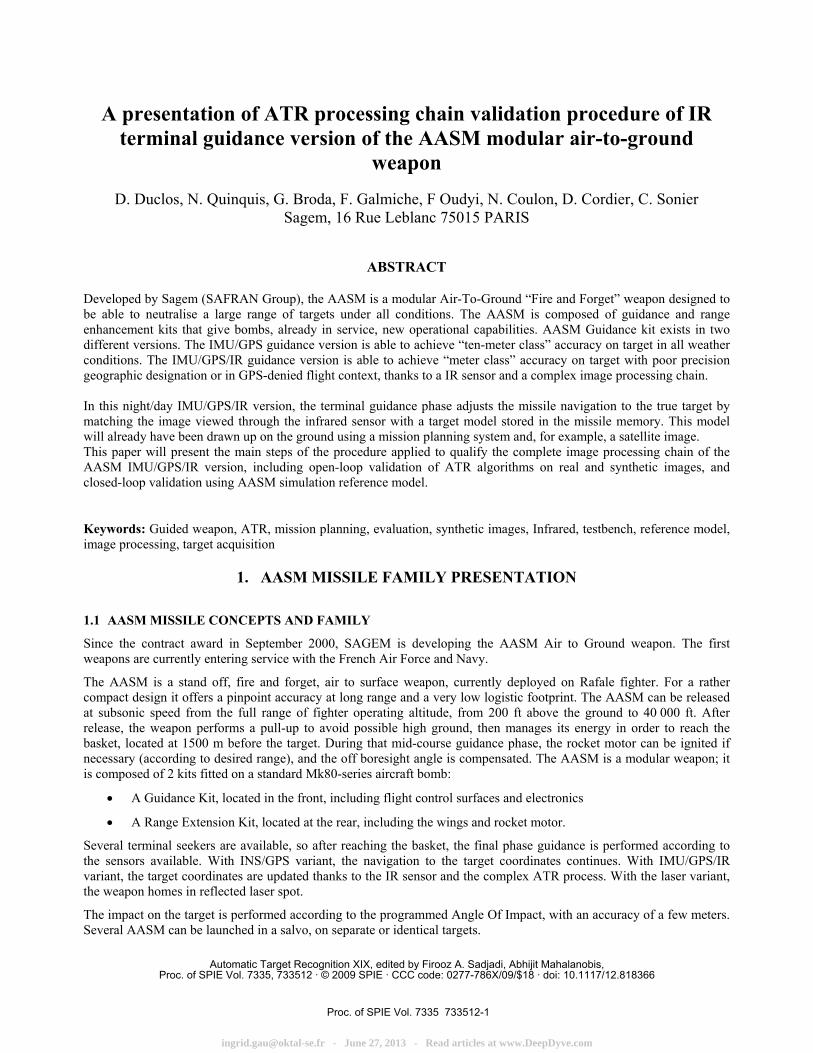
A presentation of ATR processing chain validation procedure of IR terminal guidance version of the AASM modular air-to-ground
weapon
D. Duclos, N. Quinquis, G. Broda, F. Galmiche, F Oudyi, N. Coulon, D. Cordier, C. Sonier Sagem, 16 Rue Leblanc 75015 PARIS
ABSTRACT
Developed by Sagem (SAFRAN Group), the AASM is a modular Air-To-Ground “Fire and Forget” weapon designed to be able to neutralise a large range of targets under all conditions. The AASM is composed of guidance and range enhancement kits that give bombs, already in service, new operational capabilities. AASM Guidance kit exists in two different versions. The IMU/GPS guidance version is able to achieve “ten-meter class” accuracy on target in all weather conditions. The IMU/GPS/IR guidance version is able to achieve “meter class” accuracy on target with poor precision geographic designation or in GPS-denied flight context, thanks to a IR sensor and a complex image processing chain. In this night/day IMU/GPS/IR version, the terminal guidance phase adjusts the missile navigation to the true target by matching the image viewed through the infrared sensor with a target model stored in the missile memory. This model will already have been drawn up on the ground using a mission planning system and, for example, a satellite image. This paper will present the main steps of the procedure applied to qualify the complete image processing chain of the AASM IMU/GPS/IR version, including open-loop validation of ATR algorithms on real and synthetic images, and closed-loop validation using AASM simulation reference model.
Keywords: Guided weapon, ATR, mission planning, evaluation, synthetic images, Infrared, testbench, reference model, image processing, target acquisition
1. AASM MISSILE FAMILY PRESENTATION 1.1 AASM MISSILE CONCEPTS AND FAMILY
Since the contract award in September 2000, SAGEM is developing the AASM Air to Ground weapon. The first weapons are currently entering service with the French Air Force and Navy.
The AASM is a stand off, fire and forget, air to surface weapon, currently deployed on Rafale fighter. For a rather compact design it offers a pinpoint accuracy at long range and a very low logistic footprint. The AASM can be released at subsonic speed from the full range of fighter operating altitude, from 200 ft above the ground to 40 000 ft. After release, the weapon performs a pull-up to avoid possible high ground, then manages its energy in order to reach the basket, located at 1500 m before the target. During that mid-course guidance phase, the rocket motor can be ignited if necessary (according to desired range), and the off boresight angle is compensated. The AASM is a modular weapon; it is composed of 2 kits fitted on a standard Mk80-series aircraft bomb:
• A Guidance Kit, located in the front, including flight control surfaces and electronics
• A Range Extension Kit, located at the rear, including the wings and rocket motor.
Several terminal seekers are available, so after reaching the basket, the final phase guidance is performed according to the sensors available. With INS/GPS variant, the navigation to the target coordinates continues. With IMU/GPS/IR variant, the target coordinates are updated thanks to the IR sensor and the complex ATR process. With the laser variant, the weapon homes in reflected laser spot.
The impact on the target is performed according to the programmed Angle Of Impact, with an accuracy of a few meters. Several AASM can be launched in a salvo, on separate or identical targets.
Automatic Target Recognition XIX, edited by Firooz A. Sadjadi, Abhijit Mahalanobis,Proc. of SPIE Vol. 7335, 733512 · © 2009 SPIE · CCC code: 0277-786X/09/$18 · doi: 10.1117/12.818366
Proc. of SPIE Vol. 7335 733512-1
[email protected] - June 27, 2013 - Read articles at www.DeepDyve.com
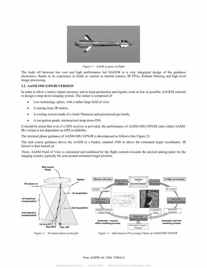
Figure 1 – AASM weapon in flight
The trade off between low cost and high performance led SAGEM to a very integrated design of the guidance electronics, thanks to its experience in fields as various as inertial sensors, IR FPAs, Kalman filtering and high level image processing,
1.2 AASM IMU/GPS/IR VERSION
In order to allow a metric impact accuracy and to keep production and logistic costs as low as possible, SAGEM selected to design a strap down imaging system. The seeker is composed of:
• Low technology optics, with a rather large field of view,
• A staring array IR matrix,
• A cooling system made of a Joule-Thomson and pressurized gas bottle,
• A navigation-grade, miniaturized strap down INS.
It should be noted that even if a GPS receiver is provided, the performance of AASM IMU/GPS/IR (also called AASM-IR) variant is not dependent on GPS availability.
The terminal phase guidance of AASM IMU/GPS/IR is decomposed as follows (See Figure 2):
The mid course guidance drives the AASM to a basket, situated 1500 m above the estimated target coordinates. IR Sensor is then turned on.
There, AASM Field of View is orientated and stabilized by the flight controls towards the desired aiming point for the imaging system; typically the area around estimated target position.
2nd Acquisition
IR sensor on
Real DPI
Basket
1st Acquisition
Est. DPI1st Acq DPI
1st trajectory compensation
2nd trajectory compensation
Mid course Phase
2nd Acquisition
IR sensor on
Real DPI
Basket
1st Acquisition
Est. DPI1st Acq DPI
1st trajectory compensation
2nd trajectory compensation
Mid course Phase
Daniel
In-flight processingTARGET+
ENVIRONMENT
Mission planningObservation
MeansObservation
Means
InputImagesDTED
Automatic + manualoffline modeling process
AASM On-BoardTarget Model
Target Area Modeling
Target Area Modeling
OnboardIR sensorOnboardIR sensor
IR Images
Low LevelImage Processing
Low LevelImage Processing
ExtractedFeatures
Automatic real-timemodeling process
Localisation Data
High levelMatching Process
High levelMatching Process
Estimated Target’s Position
Figure 2 – Terminal phase principle Figure 3 – Information Processing Chain of AASM IMU/GPS/IR
Proc. of SPIE Vol. 7335 733512-2
[email protected] - June 27, 2013 - Read articles at www.DeepDyve.com
Several pictures of the scene are taken, and the Automatic Target Recognition algorithms look for the match between the On-board Model and the observed scene. The result is an error vector, representing in geographical coordinates the distance between estimated and observed target’s localisation. This vector is supplied to the guidance algorithms, which command a course correction in order to meet the new coordinates estimation.
This acquisition process is done two times, firstly in order to locate the target, secondly in order to reach the specified accuracy of impact.
The global information processing chain of AASM IMU/GPS/IR version is presented in figure 3.
This chain is composed of two sub-chains : Mission Planning Processing and On Board Real-Time Processing. The coherence and the joint optimisation of these two sub chains are mandatory in order to obtain both impact precision and ATR robustness in all operational conditions and for all the specified types of target.
Mission Planning process starts with an input image of the target area, completed by Terrain Elevation information. From this data, an AASM On-Board Model is produced by a military photo-interpreter, helped with automatic data processing and filtering tools. The main parameters of this On-Board Model are: model’s surface, completeness of modelling, global and relative precision of localisation of model components.
Real-Time On-Board Processing performs a similar modelling task but automatically and using an IR image. Rough localisation information provided by IMU allows the initiation of the ATR process. A set of low level features are extracted from IR image and a High Level Matching process is used to research the optimal correlation between IR features and On-Board Model. The vector of corrected position of the target is then computed.
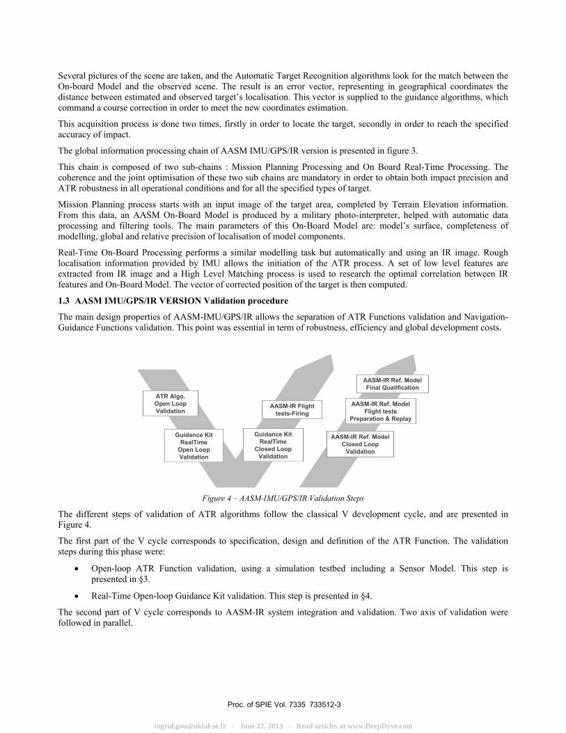
1.3 AASM IMU/GPS/IR VERSION Validation procedure
The main design properties of AASM-IMU/GPS/IR allows the separation of ATR Functions validation and Navigation-Guidance Functions validation. This point was essential in term of robustness, efficiency and global development costs.
ATR Algo.Open LoopValidation
Guidance KitRealTime
Open LoopValidation
Guidance Kit RealTime
Closed LoopValidation
AASM-IR Flight tests-Firing
AASM-IR Ref. Model Closed Loop
Validation
AASM-IR Ref. Model Flight tests
Preparation & Replay
AASM-IR Ref. Model Final Qualification
ATR Algo.Open LoopValidation
Guidance KitRealTime
Open LoopValidation
Guidance Kit RealTime
Closed LoopValidation
AASM-IR Flight tests-Firing
AASM-IR Ref. Model Closed Loop
Validation
AASM-IR Ref. Model Flight tests
Preparation & Replay
AASM-IR Ref. Model Final Qualification
Figure 4 – AASM-IMU/GPS/IR Validation Steps
The different steps of validation of ATR algorithms follow the classical V development cycle, and are presented in Figure 4.
The first part of the V cycle corresponds to specification, design and definition of the ATR Function. The validation steps during this phase were:
• Open-loop ATR Function validation, using a simulation testbed including a Sensor Model. This step is presented in §3.
• Real-Time Open-loop Guidance Kit validation. This step is presented in §4.
The second part of V cycle corresponds to AASM-IR system integration and validation. Two axis of validation were followed in parallel.
Proc. of SPIE Vol. 7335 733512-3
[email protected] - June 27, 2013 - Read articles at www.DeepDyve.com
0
SE
-SC
EN
AR
IO
SE
-TO
OLK
IT
SE
-RA
Y-I
R-S
EN
S0R
'S
EF
ST
IRS
EN
S0R
SE
-RA
Y
-c
The first axis addressed Real-Time AASM-IR validation and included the following steps: AASM-IR Closed-loop Validation on bench, presented in §6, and AASM-IR Flights and Firings.
The second axis addressed integration, validation and use of AASM-IR Reference Model for AASM-IR final performance qualification. It included the following steps:
• AASM-IR Reference Model Closed-loop validation, presented in §3, and
• AASM-IR Firing Preparation and Replay, presented in §7.
• And finally, after full validation of each models, use of AASM-IR Reference Model for AASM-IR qualification of performances, based on similar means and methods to those for AASM-IR Reference Model Closed-loop validation
Most of the physical and simulation testbenches used at the different stages of validation process use a specific IR Synthetic Image Generation Workbench. This Workbench based on OKTAL SE modules is presented in the next chapter.
2. IR SYNTHETIC IMAGE GENERATION WORKBENCH 2.1 Sagem workbench based on OKTAL SE products.
The development and validation process of the algorithm have been mainly realized using synthetic infrared images. These images have been produced by a dedicated IR Synthetic Image Generation TestBench based on OKTAL SE Workbench and a home made sensor model.
SE-WORKBENCH, also called CHORALE, is a multi-sensor battlefield modeling workbench developed by OKTAL SE and mainly used by French MoD, German BWB and by South Korea MoD, in order to achieve the synthesis of a 3D scene observed by an optronic or electronic sensor. The process of modeling and data generation is done in two steps:
• The physical characterization of the 3D scene behavior
• The computation of the physical signal received by a sensor
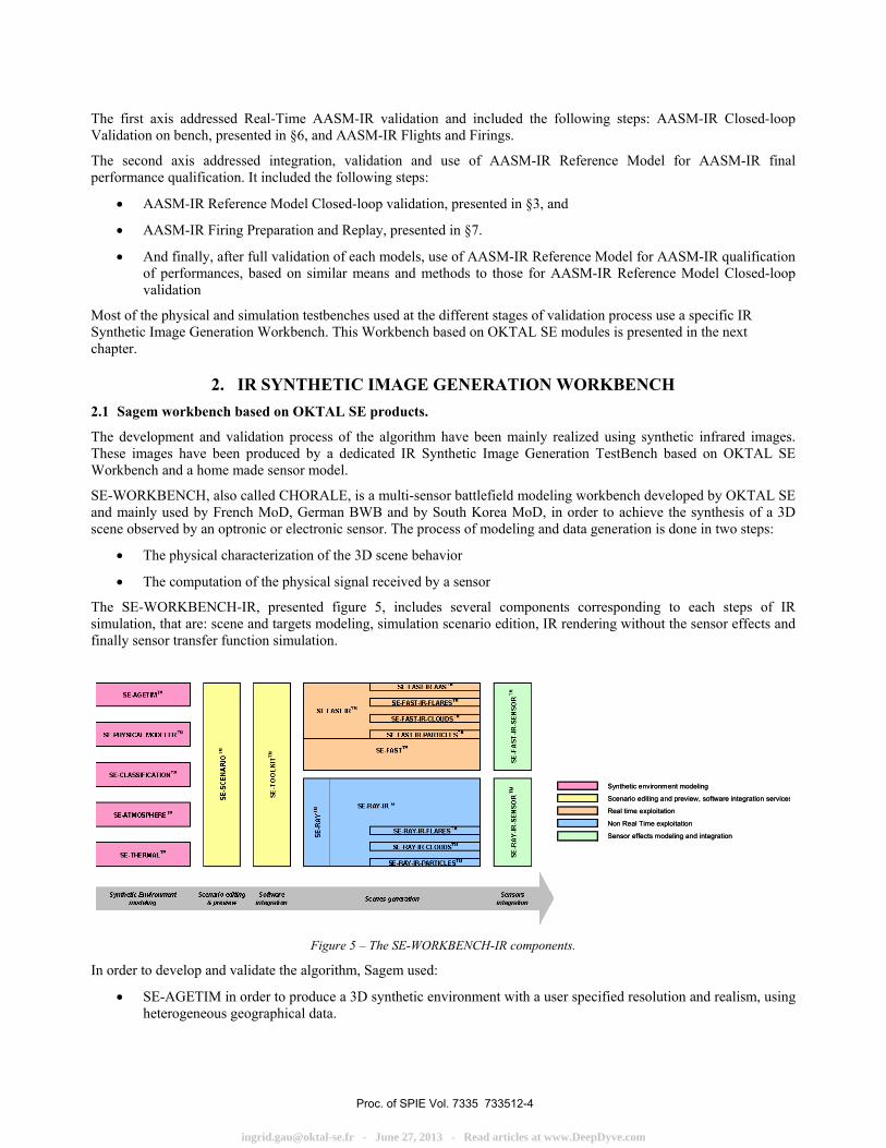
The SE-WORKBENCH-IR, presented figure 5, includes several components corresponding to each steps of IR simulation, that are: scene and targets modeling, simulation scenario edition, IR rendering without the sensor effects and finally sensor transfer function simulation.
Synthetic environment modeling
Scenario editing and preview, software integration services
Real time exploitation
Non Real Time exploitation
Sensor effects modeling and integration
Synthetic environment modeling
Scenario editing and preview, software integration services
Real time exploitation
Non Real Time exploitation
Sensor effects modeling and integration
Figure 5 – The SE-WORKBENCH-IR components.
In order to develop and validate the algorithm, Sagem used:
• SE-AGETIM in order to produce a 3D synthetic environment with a user specified resolution and realism, using heterogeneous geographical data.
Proc. of SPIE Vol. 7335 733512-4
[email protected] - June 27, 2013 - Read articles at www.DeepDyve.com

V
• SE-PHYSICAL-MODELER in order to characterize the physical properties of all the elements of the scene.
• SE-CLASSIFICATION in order to classify texture of physical materials.
• SE-ATMOSPHERE in order to characterize different atmospheres using codes like MODTRAN.
• SE-THERMAL in order to calculate temperature states of a scene for different atmospheres.
• SE-ADVANCED-SCENE-RAY for the construction of the different scenarios.
• SE-RAY-IR which is the ray tracing kernel developed by OKTAL-SE in order to compute high realism images.
• SE-TOOLKIT in order to control the generated scenario execution from a remote application.
2.2 3D Models
Twelve different synthetic scenes have been produced and used during ATR algorithm development. Those scenes are based on real locations and have a surface between two and four square kilometres. Data used to specify these models included: high resolution visible aerial images, 3D geographic data when available, aerial IR sequences recorded during dedicated flights, ground observations and pictures.
Those locations have been chosen in order to represent the diversity of:
• Military targets types and configuration (Airport, Industry Plants, Bridges, Military camps, Harbours, Ground/Air Missiles Launchers site, ..),
• Target area complexity, from very dense to very sparse,
• Vegetation and natural elements density,
• Local terrain elevation, from flat to severe.
Fig. 6: Examples of Radiance IR synthetic images.
Ten other synthetic scenes have been used for the final ATR algorithm validation. These 3D models have been produced by French MoD services and are far more detailed than the one used for the algorithm development. They have been chosen on the same criteria as those used for the development.
2.3 AASM-IR Sensor Model
The SE Workbench produces “perfect” radiance images of any size on any specified waveband. Sagem developed a sensor model in order to transform those images into images similar to those obtained with the real AASM IR system. This software models all the main sensor’s parameters : optical distortion, optical transfer function, parasite flux, IR detector sensibility, and response (offset and noise), electronics noise, dead pixels (corrected and uncorrected), calibration process.
Proc. of SPIE Vol. 7335 733512-5
[email protected] - June 27, 2013 - Read articles at www.DeepDyve.com
Several versions of this sensor model have been developed and used, starting from a specifications model, at the beginning of the project, and ending with a fully validated model of the real sensor for the final qualification phase.
2.4 Validation process
Each module of SE Workbed has been validated by OKTAL SE. Furthermore this workbed was used in several previous French MoD studies and programs, some of which were dedicated to validation of specific modules. In order to complete these validations, Sagem compared real IR images and synthetic ones produced on the same operational situation, along the same trajectory, and with a sensor model representing the real IR sensor. This comparison was done in two steps :
IR images were compared visually and statistically to identify the potential differences between the real scene and the 3D model, in terms of geometric and physical characterisation of the objects and natural background. When available, several weather or hour/date conditions were exploited.
Then ATR results on real and synthetic images were compared: firstly the accuracy of the performances of the ATR process, secondly the automatic estimation of confidence in the output results.
These analyses showed that no significant difference exists between real and synthetic images and between ATR performances obtained on these two types of input data.
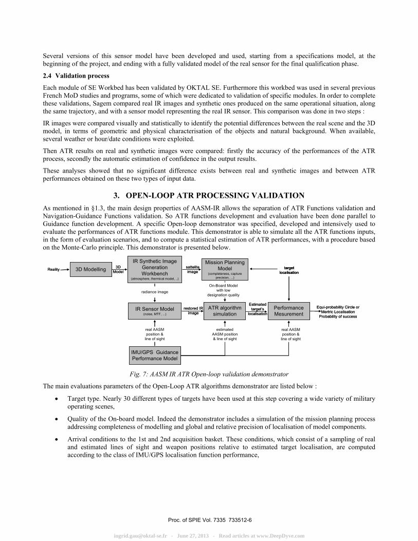
3. OPEN-LOOP ATR PROCESSING VALIDATION As mentioned in §1.3, the main design properties of AASM-IR allows the separation of ATR Functions validation and Navigation-Guidance Functions validation. So ATR functions development and evaluation have been done parallel to Guidance function development. A specific Open-loop demonstrator was specified, developed and intensively used to evaluate the performances of ATR functions module. This demonstrator is able to simulate all the ATR functions inputs, in the form of evaluation scenarios, and to compute a statistical estimation of ATR performances, with a procedure based on the Monte-Carlo principle. This demonstrator is presented below.
IR Synthetic ImageGenerationWorkbench
(atmosphere, thermical model, ..)
3D Modelling
IR Sensor Model(noise, MTF, ...)
ATR algorithmsimulation
IMU/GPS GuidancePerformance Model
PerformanceMesurement
Mission PlanningModel
(completeness, captureprecision, ...)
Reality 3DModel
Equi-probability Circle orMertric Localisation
Probability of success
Estimatedtarget’s
localisation
targetlocalisation
satteliteimage
real AASMposition &
line of sight
estimatedAASM position& line of sight
real AASMposition &
line of sight
restored IRimage
radiance imageOn-Board Model
with lowdesignation quality
IR Synthetic ImageGenerationWorkbench
(atmosphere, thermical model, ..)
3D Modelling
IR Sensor Model(noise, MTF, ...)
ATR algorithmsimulation
IMU/GPS GuidancePerformance Model
PerformanceMesurement
Mission PlanningModel
(completeness, captureprecision, ...)
Reality 3DModel
Equi-probability Circle orMertric Localisation
Probability of success
Estimatedtarget’s
localisation
targetlocalisation
targetlocalisation
satteliteimage
real AASMposition &
line of sight
estimatedAASM position& line of sight
real AASMposition &
line of sight
restored IRimage
radiance imageOn-Board Model
with lowdesignation quality
Fig. 7: AASM IR ATR Open-loop validation demonstrator
The main evaluations parameters of the Open-Loop ATR algorithms demonstrator are listed below :
• Target type. Nearly 30 different types of targets have been used at this step covering a wide variety of military operating scenes,
• Quality of the On-board model. Indeed the demonstrator includes a simulation of the mission planning process addressing completeness of modelling and global and relative precision of localisation of model components.
• Arrival conditions to the 1st and 2nd acquisition basket. These conditions, which consist of a sampling of real and estimated lines of sight and weapon positions relative to estimated target localisation, are computed according to the class of IMU/GPS localisation function performance,
Proc. of SPIE Vol. 7335 733512-6
[email protected] - June 27, 2013 - Read articles at www.DeepDyve.com
• Parameters of the IR image such as the SNR (Signal to Noise Ratio), the MTF (Modulation Transfer Function), and the fixed pattern noise. They are determined by the IR sensor features and the environmental local conditions (temperature and pressure),
• Operational mission conditions , consisting of :
o the mission date and time,
o the atmospherical conditions (visibility, humidity, …).
All of those parameters have been subject to modelisation and statistical draws. This led us to conduct, for each performance validation step, more than 5 thousands open-loop runs for each target. Altogether the total amount of runs exceeds half a million.
Real IR images on the same targets have also been used for evaluation in order to consolidate performance estimations. For each target, IR sequences have been recorded at several seasons (typically spring, winter, summer) and also at several hours of the day (twilight, night, dawn, day). The constitution of this real IR images database need more than two years. The evaluations done with these real images follow the same method as those done with IR synthetic images, except than the real sensor Lines of Sight were fixed by the recorded trajectory. The performances we obtained on real images and simulated synthetic images under the same acquisition conditions (target type, aircraft trajectory, date and time ...) were identical, which permitted to qualify the whole open-loop simulator.
In implying those evaluation means at the very beginning of the project it enabled us:
• to consolidate ATR algorithmic choices and expected performances at a early step of development, even before the physical development of sensor and Guidance Kit system started,
• to adjust the IR Sensor requirements as close as possible to the ATR functions minimal needs.
Finally, during the final qualification phase, this open-loop validation process contributed to the demonstration of the weapon system performances fulfillment. Furthermore, it allowed to significantly reduce the required number of closed-loop evaluations.
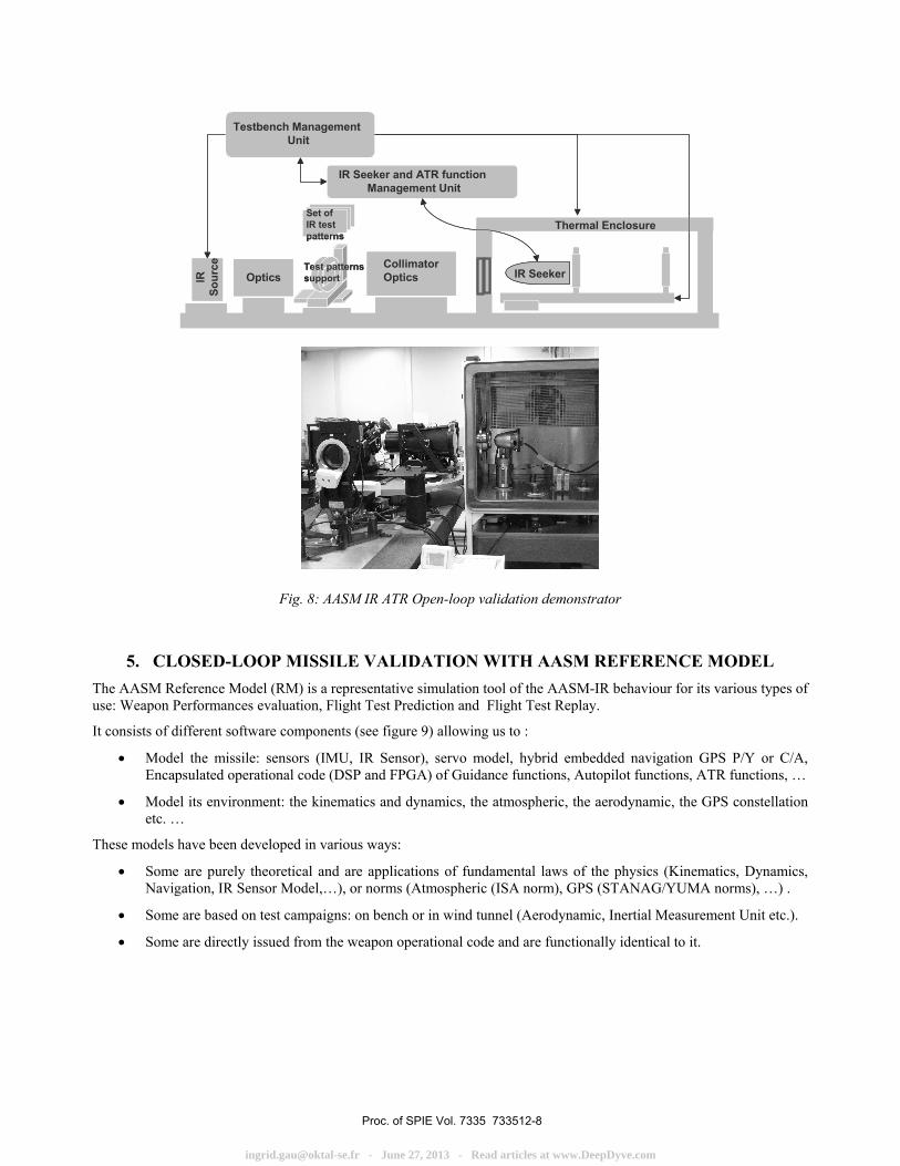
4. REAL-TIME OPEN-LOOP VALIDATION OF AASM-IR GUIDANCE KIT A specific testbench has been developed for real-time open-loop validation of AASM Guidance Kit. It has allowed the following operations :
• Real-time validation of IR Sensor performances (MTF, SNR, NETD, …) and functionalities (Cryogeny, Calibration process, …) in various thermal conditions
• Real-Time validation of IR Seeker function including ATR function, in various thermal conditions. For this second operation the testbench’s design was based on the use of innovative IR test patterns. As explained previously, due to AASM-IR design, Target acquisition phases and Trajectory compensation phases are separated. This allows to use static IR images at this level of validation, instead of IR videos which are required when the IR seeker is designed as a target tracker. The main characteristics of these realistic IR test patterns were the following :
• Size :70 x 70 mm² , Engraving resolution ; 0.1 μm equivalent to a 1024x1024 pixels image • 12 Bits IR resolution • 1st acquisition scene and 2nd acquisition scene included in a single test pattern • IR scenes generated through the IR synthetic image generator workbench presented in §2.
Several test patterns were used in order to validate the ATR Function behaviour on different types of targets. As test bench allowed us to use each test pattern in various position in term of translation, rotation and zoom, a large set of AASM arrival situations have been simulated with each single test pattern.
Proc. of SPIE Vol. 7335 733512-7
[email protected] - June 27, 2013 - Read articles at www.DeepDyve.com
Collimator OpticsIR
Sour
ce
OpticsTest patternssupport
Set of IR test patterns
IR Seeker
Testbench ManagementUnit
Thermal Enclosure
IR Seeker and ATR function Management Unit
Collimator OpticsIR
Sour
ce
OpticsTest patternssupport
Set of IR test patterns
IR Seeker
Testbench ManagementUnit
Thermal Enclosure
IR Seeker and ATR function Management Unit
Fig. 8: AASM IR ATR Open-loop validation demonstrator
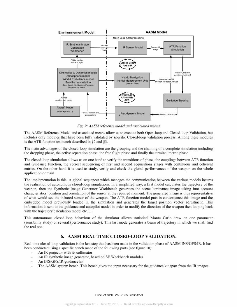
5. CLOSED-LOOP MISSILE VALIDATION WITH AASM REFERENCE MODEL The AASM Reference Model (RM) is a representative simulation tool of the AASM-IR behaviour for its various types of use: Weapon Performances evaluation, Flight Test Prediction and Flight Test Replay.
It consists of different software components (see figure 9) allowing us to :
• Model the missile: sensors (IMU, IR Sensor), servo model, hybrid embedded navigation GPS P/Y or C/A, Encapsulated operational code (DSP and FPGA) of Guidance functions, Autopilot functions, ATR functions, …
• Model its environment: the kinematics and dynamics, the atmospheric, the aerodynamic, the GPS constellation etc. …
These models have been developed in various ways:
• Some are purely theoretical and are applications of fundamental laws of the physics (Kinematics, Dynamics, Navigation, IR Sensor Model,…), or norms (Atmospheric (ISA norm), GPS (STANAG/YUMA norms), …) .
• Some are based on test campaigns: on bench or in wind tunnel (Aerodynamic, Inertial Measurement Unit etc.).
• Some are directly issued from the weapon operational code and are functionally identical to it.
Proc. of SPIE Vol. 7335 733512-8
[email protected] - June 27, 2013 - Read articles at www.DeepDyve.com
Aircraft Model(SNA, Ejectors ...)
Kinematics & Dynamics modelsAtmospheric model
Wind & Turbulence modelSatellite constellation
(Pos, Speed, Att, Dynamic Pressure,Temperature, Wind, ...)
Guidance/Steering
ATR FunctionSimulation
IR Sensor ModelIR Synthetic Image
GenerationWorkbench
Aerodynamic Model
AASM position& line of sight
intranceapertureimage
Restore IRimage
AASM/PDI relativeposition adjustment
Executed Deflections
Aircraftposition & air speed
Forces, moment andaccelerations
Hybrid NavigationInertial Measurement Unit
(Kalman Filter)
Texte Texte
Closed LoopAASM-INS/
GPS
Texte TexteClosed Loop
AASM-IR
Measured AASMPosition, Air speed,Attitude
Environnement Model AASM ModelOpen Loop ATR processing
Fig. 9: AASM reference model and associated means
The AASM Reference Model and associated means allow us to execute both Open-loop and Closed-loop Validation, but includes only modules that have been fully validated by specific Closed-loop validation process. Among these modules is the ATR function testbench described in §2 and §3.
The main advantages of the closed-loop simulation are the grouping and the chaining of a complete simulation including the dropping phase, the active separation phase, the free flight phase and finally the terminal metric phase.
The closed-loop simulation allows us on one hand to verify the transitions of phase, the couplings between ATR function and Guidance function, the correct sequencing of first and second acquisitions stages with continuous and coherent entries. On the other hand it is used to study, verify and check the global performances of the weapon on the whole application domain.
The implementation is this: A global sequencer which manages the communication between the various models insures the realisation of autonomous closed-loop simulations. In a simplified way, a first model calculates the trajectory of the weapon, then the Synthetic Image Generator Workbench generates the scene luminance image taking into account characteristics, position and orientation of the sensor at the required moment. The generated image is thus representative of what would see the infrared sensor of the weapon. The ATR function model puts in concordance this image and the embedded model previously loaded in the simulation and generates the target position vector adjustment. This information is sent to the guidance and autopilot model in order to modify the direction of the weapon then looping back with the trajectory calculation model etc. …
This autonomous closed-loop behaviour of the simulator allows statistical Monte Carlo draw on one parameter (sensibility study) or several (performance study). This last mode generates a beam of trajectory in which we shall find the real one.
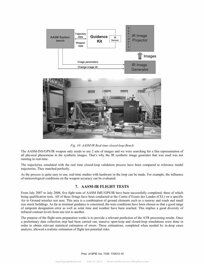
6. AASM REAL TIME CLOSED-LOOP VALIDATION. Real time closed-loop validation is the last step that has been made in the validation phase of AASM INS/GPS/IR. It has been conducted using a specific bench made of the following parts (see figure 10):
- An IR projector with its collimator - An IR synthetic image generator, based on SE Workbench modules. - An INS/GPS/IR guidance kit - The AASM system bench. This bench gives the input necessary for the guidance kit apart from the IR images.
Proc. of SPIE Vol. 7335 733512-9
[email protected] - June 27, 2013 - Read articles at www.DeepDyve.com
AASM System bench
Guidance Kit
IR Image Projector
Images
Collimator
IR Sensor
Trajectorydata
Image parametersIR Image Generator
Change image bit
Weapondata
AASM System bench
Guidance Kit
IR Image Projector
Images
Collimator
IR Sensor
Trajectorydata
Image parametersIR Image Generator
Change image bit
Weapondata
Fig. 10: AASM IR Real time closed-loop Bench
The AASM-INS/GPS/IR weapon only needs to use 2 sets of images and we were searching for a fine representation of all physical phenomena in the synthetic images. That’s why the IR synthetic image generator that was used was not running in real-time.
The trajectories simulated with the real time closed-loop validation process have been compared to reference model trajectories. They matched perfectly.
As the process is quite easy to use, real-time studies with hardware in the loop can be made. For example, the influence of meteorological conditions on the weapon accuracy can be evaluated.
7. AASM-IR FLIGHT TESTS From July 2007 to July 2008, five fight tests of AASM IMU/GPS/IR have been successfully completed, three of which being qualification tests. All of these firings have been conducted at the Centre d’Essais des Landes (CEL) on a specific Air to Ground missiles test area. This area is a combination of ground elements such as a runway and roads and small size mock buildings. As far as terminal guidance is concerned, the tests conditions have been chosen so that a good range of aimpoint designation error as well as solar time and weather have been reached. This implies a good diversity of infrared contrast levels from one test to another.
The purpose of the flight tests preparation works is to provide a relevant prediction of the ATR processing results. Once a preliminary data collection step had been carried out, massive open-loop and closed-loop simulations were done in order to obtain relevant statistical estimation of errors. These estimations, completed when needed by in-deep cases analysis, allowed a realistic estimation of flight test potential risks.
Proc. of SPIE Vol. 7335 733512-10
[email protected] - June 27, 2013 - Read articles at www.DeepDyve.com
t
As the first step of the process, a highly precise 3D model of the test area, usable by SE Workbench, has been realized. The geometric relevance is based both on high resolution aerial IR pictures and accurate topographical measurements. The relevance of the IR radiometry modelling is based on the description of the scene materials and a coarse setting using a comparison to real IR images.
The preparation of each flight tests is then divided in two main steps :
1) A data collection step including :
• Target area definition,
• Flight test parameters definition : time (meaning the date as well as the day time) and target designation error,
• Mission planning : the On-board model of the target area is made using the qualification mission planning software, using high resolution satellite imagery as main input.
• Synthetic scene adaptation to the layout and computation of atmospheric and thermal description files computation. These computations fulfil a sampling of the expected conditions (time slots and weather hypotheses) so that the sensibility to these parameters is assessed.
• IR imagery acquisition by helicopter. The device is the AASM-IR sensor, therefore the sequences share the same characteristics as the on-board pictures of the flight test.
2) The processing of this data implies three kind of simulations :
• Open-loop simulation with the synthetical environment and the fine sampling of the IR conditions (time slot and weather). This allows assessing the behaviour of the ATR function regarding radiometry variability.
• Closed-loop simulation with the synthetical environment and a coarse sampling of the IR conditions. It assesses global performance of the weapon.
• Open-loop simulation with the real IR sequences. As it generally takes place a few days before the test, it also enables us to control the aspect of the scene before firing.
Eventually data of the firings are processed to check every parameter.
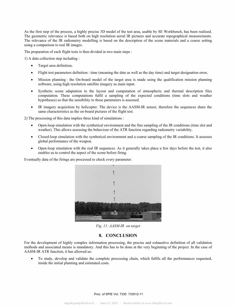
Fig. 11: AASM-IR on target
8. CONCLUSION For the development of highly complex information processing, the precise and exhaustive definition of all validation methods and associated means is mandatory. And this has to be done at the very beginning of the project. In the case of AASM-IR ATR function, it has allowed us:
• To study, develop and validate the complete processing chain, which fulfils all the performances requested, inside the initial planning and estimated costs.
Proc. of SPIE Vol. 7335 733512-11
[email protected] - June 27, 2013 - Read articles at www.DeepDyve.com
• To minimize the risks of ATR function design evolution during the project. Only minor evolutions were needed between early stage definition and final version of the algorithms.
• To ensure a complete understanding of ATR function behaviour inside its specified operational domain but also on extreme cases.
• To minimize the number of flight tests needed for final AASM-IR qualification.
Furthermore the IR Synthetic image generation workbench enabled us to develop the IR sensor and the ATR algorithms simultaneously, which was one of the key points of AASM-IR program’s success.
Most of the methods and means used for AASM-IR performance validation continue to be used for the development of the AASM-Laser version. The IR Synthetic image generation workbench is also currently used for image processing chain studies in many development programs of SAGEM optronic products such as seekers, goggles, sights, helicopter surveillance systems, …
REFERENCES
1 J-V. Legrand –SAGEM- “AASM Strap down imaging system” NATO Military Sensing Symposium Orlando, March 13-14, 2008. 2 J. Latger, T. Cathala, N. Douchin - OKTAL Synthetic Environment- A. Le Goff - DGA/DET/CELAR-, " Simulation of active and passive infrared images using the SE-WORKBENCH," SPIE Defence&Security Orlando 2007
Proc. of SPIE Vol. 7335 733512-12
[email protected] - June 27, 2013 - Read articles at www.DeepDyve.com


![Engineering Geology...AAU Office of the Registrar De 't: Civil En ineerin Program: Section: 4 course Code; CENG ID.NO ATR12152]05 ATR/5749/05 ATR/4526/05 ATR/7587/06 ATR/2774/05 ATR/5278/05](https://img.pdfslide.us/doc/110x75/60f5164ac9e9827e9d545c73/engineering-geology-aau-office-of-the-registrar-de-t-civil-en-ineerin-program.jpg)