Embed Size (px)
Citation preview
Paper 105
2019 Pacific Conference on Earthquake Engineering and Annual NZSEE Conference 1
A preliminary study on cyclic behaviour of SFS dowelled connections in glulam frames
W. Dong & M. Li University of Canterbury, Christchurch.
ABSTRACT
SFS self-drilling dowels are a special type of metal fasteners in timber construction which can go
through relatively thin steel plates and timber members without pre-drilling. The application of SFS
dowels makes wood-steel connection assembling more efficient and accurate. Due to tight fitting
between holes and fasteners, initial slips in SFS dowelled connections are much smaller than that in
conventional dowelled or bolted connections which have predrilled holes typically oversized with
1~2mm. So far, design of SFS dowelled connections in New Zealand mainly follows European
practice and very limited experimental testing has been done to validate the SFS dowelled
connection strength and stiffness with NZ Radiata Pine (RP). This paper presents a preliminary
experimental study to investigate cyclic performance of SFS dowelled connections in RP glulam
that are designed to connect diagonal braces with glulam beams and columns. Connection
properties in terms of strength, stiffness, ductility and overstrength were derived from the force-
displacement curves. The test results showed that the SFS connections performed well with high
ductility. The design equations in Eurocode 5 also provided reasonably accurate ultimate strength
and ultimate stiffness predictions.
1 INTRODUCTION
Dowel-type connections with slotted-in steel plates provide multiple shear planes of fasteners and are one of
the most efficient joint types for heavy timber structures (Figure 1). Common wood-steel-wood (WSW)
dowelled or bolted connections require considerable manufacturing efforts including accurate drilling
because fabrication tolerances can affect the performance of the connections (Mischler, et al.2000).
However, to easily assemble dowels into steel plates and timber members, oversized holes are usually
predrilled and often cause significant initial slip with reduced stiffness of the connections.

Paper 105 – A preliminary study on cyclic behaviour of SFS dowelled connections in glulam frames
2019 Pacific Conference on Earthquake Engineering and Annual NZSEE Conference 2
Figure 1: Beatrice Tinsley Building at University
of Canterbury
Figure 2: Building scenario for specimen design
SFS self-drilling dowels are a type of special fasteners which can go through timber members and relatively
thin steel plates without pre-drilling. SFS dowels are commercially available in 7mm diameters and are
considered as slender fasteners manufactured by high strength steel. As a proprietary product, very limited
research on SFS dowels has been reported in literature. Mischler (2001) conducted axial monotonic tests of
SFS dowelled connections in Norway spruce and observed high load-carrying capacity and ductile
behaviour. Schreyer et al. (2004) conducted a series of dowelled connection tests in Parallel Strand Lumber
(PSL) and compared test results between slender common dowels and SFS dowels and concluded that SFS
dowels had overall comparable performance to common slender dowels with slightly improved monotonic
stiffness and strength. Lau (2006) carried out compressive tests of SFS dowelled connections in Laminated
Veneered Lumber (LVL) and found the connections performed better than bolted connections in terms of
strength and stiffness. In New Zealand, SFS dowelled connections have been applied in timber construction
and the design method mainly follows European Yield Models (EYMs) in Eurocode 5 (2004) since Timber
Structures Standard NZS3603(1993) does not include this specific type of fasteners. Although generally
treated as a slender dowel fastener, there is limited knowledge of the cyclic behaviour of SFS dowels with
New Zealand RP glulam structure. Therefore, this study aims to understand the behaviour of the SFS
dowelled connections under cyclic loading and the results are used to check against the prediction accuracy
of the design equations.
2 EXPERIMENTAL PROGRAMME
2.1 Specimen design and material property
As shown in Figure 2, a six-storey glulam frame structure with chevron braces was used as the design
scenario. The SFS dowelled connections were designed to connect the braces to the beams and columns. The
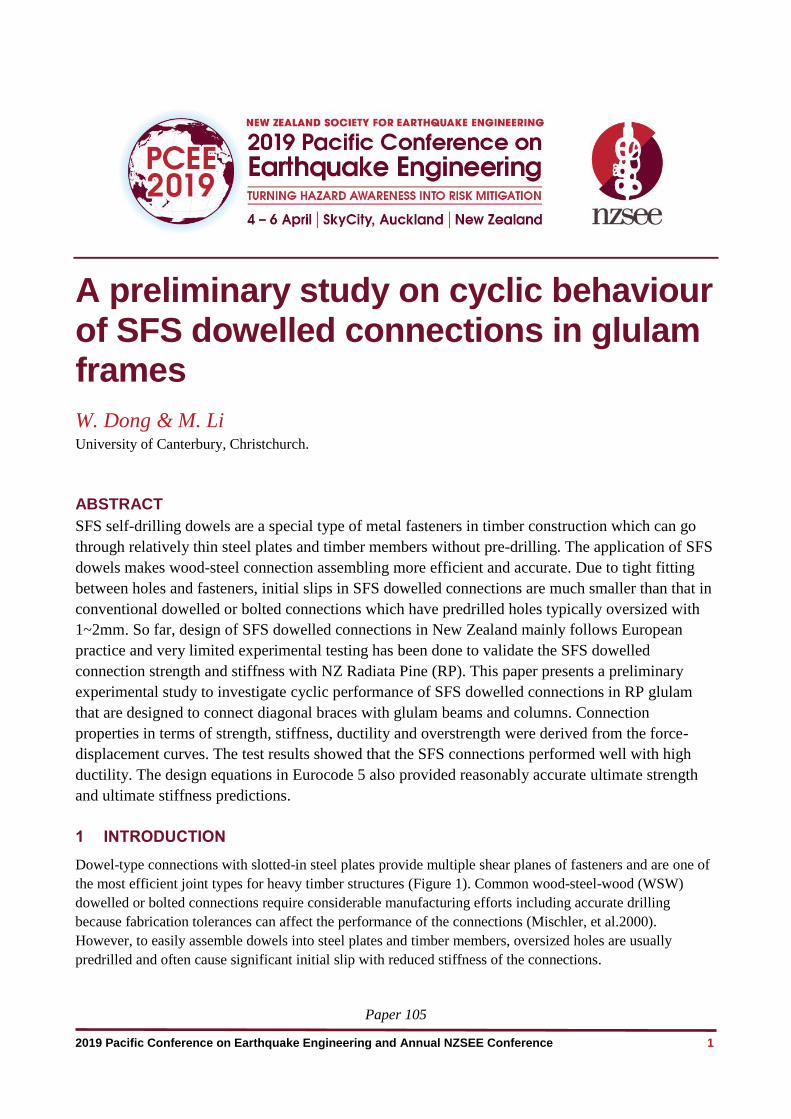
layout of the connection specimen is shown in Figure 3. The component B-1 and C-1 were used to simulate
the beam and column in the design building. GL10 RP glulam was used for B-1 and C-1 and the design
properties are specified by NZS3603. The average moisture content of the glulam members was 14% and the
average density was 478 kg/m3. The cross sections of B-1 and C-1 were 270mm x 225mm and 225mm x
225mm respectively. Two 8 mm wide slots were cut in B-1 and C-1 by a Computer Numerical Control
(CNC) machine and two 6 mm thick steel gusset plates (S-1) were inserted into B-1 and C-1. One Φ60 mm
Paper 105 – A preliminary study on cyclic behaviour of SFS dowelled connections in glulam frames
2019 Pacific Conference on Earthquake Engineering and Annual NZSEE Conference 3
hole was drilled on each gusset plate to connect the actuator with a pinned connection. 6mm ring pads were
welded around the hole to avoid any potential for local yielding around the holes. The steel plates had Grade
300 according to AS/NZS 3678 (2016).
Nine Φ7x173mm SFS dowels were used to fix S-1 to B-1 and C-1. The characteristic yield moment of SFS
dowels is 31.93 kN·mm based on the supplier’s document (Rothoblaas, (2017), which corresponds to a
characteristic ultimate tensile strength of 675MPa according to Eurocode 5. Because B-1 and C-1 were
225mm thick, the SFS dowels were overdriven 20mm into the surface of B-1 and C-1. This centred the SFS
dowels in the connection. The actuator applied the axial loading action from the braces in the design building
and transferred the loads to the joints via the gusset plates.
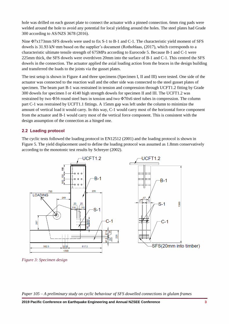
The test setup is shown in Figure 4 and three specimens (Specimen I, II and III) were tested. One side of the
actuator was connected to the reaction wall and the other side was connected to the steel gusset plates of
specimen. The beam part B-1 was restrained in tension and compression through UCFT1.2 fitting by Grade
300 dowels for specimen I or 4140 high strength dowels for specimen II and III. The UCFT1.2 was
restrained by two Φ36 round steel bars in tension and two Φ70x6 steel tubes in compression. The column
part C-1 was restrained by UCFT1.1 fittings. A 15mm gap was left under the column to minimize the
amount of vertical load it would carry. In this way, C-1 would carry most of the horizontal force component
from the actuator and B-1 would carry most of the vertical force component. This is consistent with the
design assumption of the connection as a hinged one.
2.2 Loading protocol
The cyclic tests followed the loading protocol in EN12512 (2001) and the loading protocol is shown in
Figure 5. The yield displacement used to define the loading protocol was assumed as 1.8mm conservatively
according to the monotonic test results by Schreyer (2002).
Figure 3: Specimen design
Paper 105 – A preliminary study on cyclic behaviour of SFS dowelled connections in glulam frames
2019 Pacific Conference on Earthquake Engineering and Annual NZSEE Conference 4
Figure 4: Test setup
Figure 5: Loading protocol from EN12512
(2001)
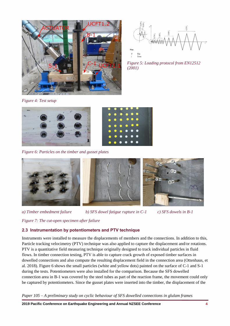
Figure 6: Particles on the timber and gusset plates
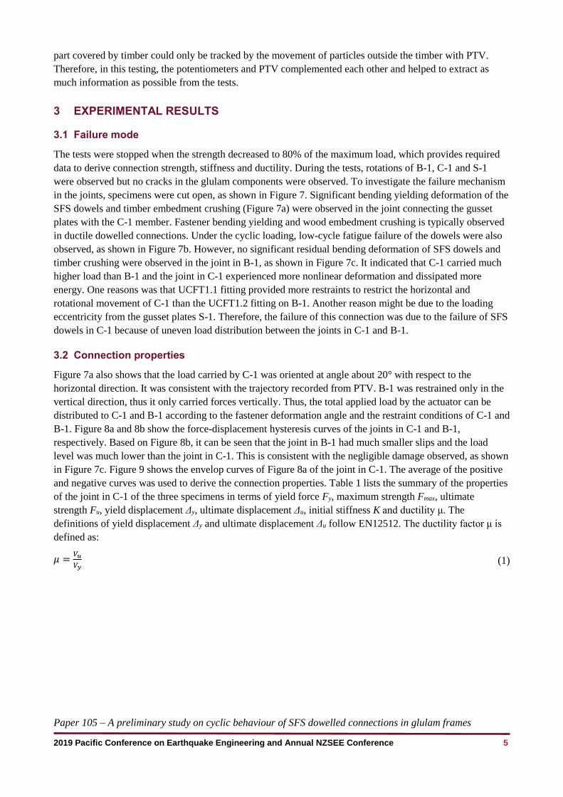
a) Timber embedment failure b) SFS dowel fatigue rupture in C-1 c) SFS dowels in B-1
Figure 7: The cut-open specimen after failure
2.3 Instrumentation by potentiometers and PTV technique
Instruments were installed to measure the displacements of members and the connections. In addition to this,
Particle tracking velocimetry (PTV) technique was also applied to capture the displacement and/or rotations.
PTV is a quantitative field measuring technique originally designed to track individual particles in fluid
flows. In timber connection testing, PTV is able to capture crack growth of exposed timber surfaces in
dowelled connections and also compute the resulting displacement field in the connection area (Ottenhaus, et
al. 2018). Figure 6 shows the small particles (white and yellow dots) painted on the surface of C-1 and S-1
during the tests. Potentiometers were also installed for the comparison. Because the SFS dowelled
connection area in B-1 was covered by the steel tubes as part of the reaction frame, the movement could only
be captured by potentiometers. Since the gusset plates were inserted into the timber, the displacement of the
Paper 105 – A preliminary study on cyclic behaviour of SFS dowelled connections in glulam frames
2019 Pacific Conference on Earthquake Engineering and Annual NZSEE Conference 5
part covered by timber could only be tracked by the movement of particles outside the timber with PTV.
Therefore, in this testing, the potentiometers and PTV complemented each other and helped to extract as
much information as possible from the tests.
3 EXPERIMENTAL RESULTS
3.1 Failure mode
The tests were stopped when the strength decreased to 80% of the maximum load, which provides required
data to derive connection strength, stiffness and ductility. During the tests, rotations of B-1, C-1 and S-1
were observed but no cracks in the glulam components were observed. To investigate the failure mechanism
in the joints, specimens were cut open, as shown in Figure 7. Significant bending yielding deformation of the
SFS dowels and timber embedment crushing (Figure 7a) were observed in the joint connecting the gusset
plates with the C-1 member. Fastener bending yielding and wood embedment crushing is typically observed
in ductile dowelled connections. Under the cyclic loading, low-cycle fatigue failure of the dowels were also
observed, as shown in Figure 7b. However, no significant residual bending deformation of SFS dowels and
timber crushing were observed in the joint in B-1, as shown in Figure 7c. It indicated that C-1 carried much
higher load than B-1 and the joint in C-1 experienced more nonlinear deformation and dissipated more
energy. One reasons was that UCFT1.1 fitting provided more restraints to restrict the horizontal and
rotational movement of C-1 than the UCFT1.2 fitting on B-1. Another reason might be due to the loading
eccentricity from the gusset plates S-1. Therefore, the failure of this connection was due to the failure of SFS
dowels in C-1 because of uneven load distribution between the joints in C-1 and B-1.
3.2 Connection properties
Figure 7a also shows that the load carried by C-1 was oriented at angle about 20° with respect to the
horizontal direction. It was consistent with the trajectory recorded from PTV. B-1 was restrained only in the
vertical direction, thus it only carried forces vertically. Thus, the total applied load by the actuator can be
distributed to C-1 and B-1 according to the fastener deformation angle and the restraint conditions of C-1 and
B-1. Figure 8a and 8b show the force-displacement hysteresis curves of the joints in C-1 and B-1,
respectively. Based on Figure 8b, it can be seen that the joint in B-1 had much smaller slips and the load
level was much lower than the joint in C-1. This is consistent with the negligible damage observed, as shown
in Figure 7c. Figure 9 shows the envelop curves of Figure 8a of the joint in C-1. The average of the positive
and negative curves was used to derive the connection properties. Table 1 lists the summary of the properties
of the joint in C-1 of the three specimens in terms of yield force Fy, maximum strength Fmax, ultimate
strength Fu, yield displacement Δy, ultimate displacement Δu, initial stiffness K and ductility μ. The
definitions of yield displacement Δy and ultimate displacement Δu follow EN12512. The ductility factor μ is
defined as:
𝜇 =𝑉𝑢
𝑉𝑦 (1)

Paper 105 – A preliminary study on cyclic behaviour of SFS dowelled connections in glulam frames
2019 Pacific Conference on Earthquake Engineering and Annual NZSEE Conference 6
a) C-1 connection for three specimens b) B-1 connection for specimen III
Figure 8: Force-displacement curve of the specimens
Figure 9: Envelope force-displacement cycle curves
Table 1: The specimens test results
Specimen No. Specimen I Specimen II Specimen III Average
Fy (kN) 147.5 154.3 158.0 153.3
Fmax(kN) 204.5 209.0 212.9 208.8
Fu(kN) 163.6 167.2 170.3 167.0
Δy(mm) 1.3 1.6 0.9 1.31
Δu(mm) 14.3 13.5 12.4 13.4
K(kN/mm) 119.5 90.8 169.5 126.6
μ 10.8 8.3 13.1 10.8
-250
-200
-150
-100
-50
0
50
100
150
200
250
-25 -20 -15 -10 -5 0 5 10 15 20 25
Fo
rce(
kN
)
Displacement (mm)
Specimen I
Specimen II
Specimen III-200
-150
-100
-50
0
50
100
150
200
-4 -2 0 2 4
Fo
rce
(kN
)
Displacement (mm)
Specimen I
Specimen II
Specimen III
-250
-150
-50
50
150
250
-25 -15 -5 5 15 25
Fo
rce
(kN
)
Displacement (mm)
Specimen I
Specimen II
Specimen III
Positive design value
Negative design value

Paper 105
2019 Pacific Conference on Earthquake Engineering and Annual NZSEE Conference 7
Figure 10: Stiffness degradation
Figure 11: Energy dissipation curve
3.2.1 Stiffness degradation
Stiffness degradation is an important parameter to estimate the performance of the connections under cyclic
loading. The secant stiffness of each loading cycle was calculated by Equation 2:
𝐾𝑖 =|𝐹𝑖𝑝|+|𝐹𝑖𝑛|
|∆𝑖𝑝|+|∆𝑖𝑛| (2)
where 𝐹𝑖𝑝= the maximum positive load of cycle i; 𝐹𝑖𝑛= the maximum negative load of cycle i; ∆𝑖𝑝= the
displacement corresponding to 𝐹𝑖𝑝; ∆𝑖𝑛= the displacement corresponding to 𝐹𝑖𝑛
Figure 10 shows the decrease of the stiffness with the increase of the displacement. As illustrated, the initial
stiffness was high due to the tight fit of the SFS dowels. It decreased to half of the initial stiffness at around
3mm because the wood embedment started to crush and the fasteners started to yield. However, From Figure
8b, the joint in B-1 did not show much yielding and stiffness degradation after 3mm’s displacement. The
reason is that the displacement contains the fastener slip in UCFT1.2 fitting which has oversized holes as
well. Also the displacement of SFS dowel group was recorded by potentiometers which included horizontal
displacement component as well.
3.2.2 Energy dissipation
The energy dissipation capacity of connection is critical for timber construction under severe earthquakes
and it plays a key role for the structure to sustain the loads and prevent collapse. Figure 11 shows the
accumulative energy dissipation curve by evaluating the enclosed area of the force-displacement hysteretic
loops in Figure 8a. The hysteretic energy dissipation was small during the first eleven loading cycles with
small displacement magnitude, indicating that the SFS dowels behaved approximately elastically up to a
maximum deformation of 1.85mm. After that, the SFS dowels started to yield, the energy dissipation
increased significantly.
3.3 Design predictions vs. test results
The strength and stiffness of the connections can be predicted by Equation 3 to Equation 12 according to the
Eurocode 5. For each SFS dowel, four shear planes are considered.
𝑛𝑒𝑓 = min {𝑛, 𝑛0.9√
𝑎1
13𝑑
4} (3)
𝐹𝑣,𝑅𝑘 = min
{
𝑓ℎ,𝛼,𝑘𝑡1𝑑
𝑓ℎ,𝛼,𝑘𝑡1𝑑 [√2 +4𝑀𝑦,𝑅𝑘
𝑓ℎ,1,𝑘𝑑𝑡12 − 1] +
𝐹𝑎𝑥,𝑅𝑘
4
2.3√𝑀𝑦,𝑅𝑘𝑓ℎ,𝛼,𝑘𝑑 +𝐹𝑎𝑥,𝑅𝑘
4
(4)
0
20
40
60
80
100
120
140
160
180
0 5 10 15 20
Sti
ffnes
s (k
N/m
m)
Displacement (mm)
Specimen I
Specimen II
Specimen III
Kser,sum
Ku,sum
0
2000
4000
6000
8000
10000
12000
14000
16000
18000
20000
0 5 10 15 20 25
Ener
gy (
J)
Cycle No.
Specimen I
Specimen II
Specimen III
Paper 105 – A preliminary study on cyclic behaviour of SFS dowelled connections in glulam frames
2019 Pacific Conference on Earthquake Engineering and Annual NZSEE Conference 8
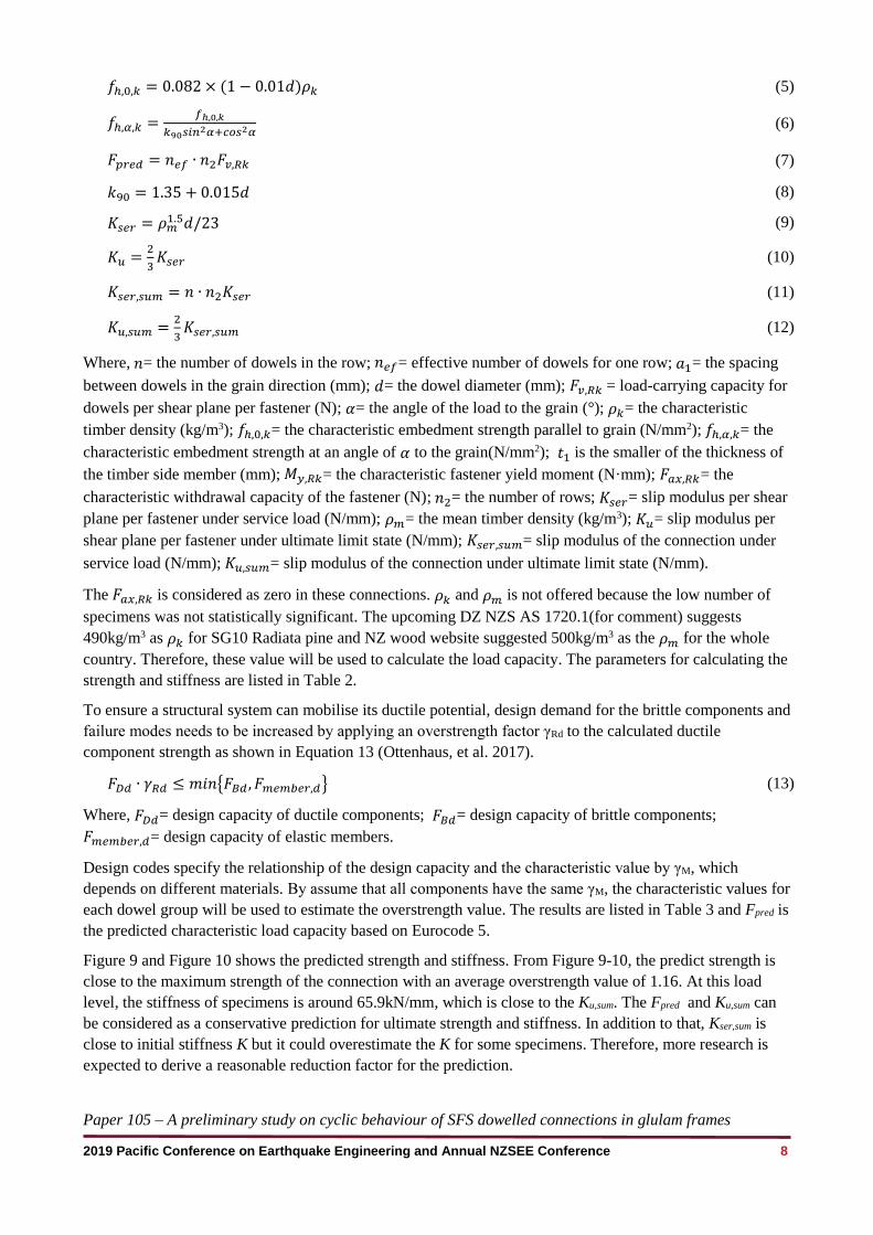
𝑓ℎ,0,𝑘 = 0.082 × (1 − 0.01𝑑)𝜌𝑘 (5)
𝑓ℎ,𝛼,𝑘 =𝑓ℎ,0,𝑘
𝑘90𝑠𝑖𝑛2𝛼+𝑐𝑜𝑠2𝛼
(6)
𝐹𝑝𝑟𝑒𝑑 = 𝑛𝑒𝑓 ∙ 𝑛2𝐹𝑣,𝑅𝑘 (7)
𝑘90 = 1.35 + 0.015𝑑 (8)
𝐾𝑠𝑒𝑟 = 𝜌𝑚1.5𝑑/23 (9)
𝐾𝑢 =2
3𝐾𝑠𝑒𝑟 (10)
𝐾𝑠𝑒𝑟,𝑠𝑢𝑚 = 𝑛 ∙ 𝑛2𝐾𝑠𝑒𝑟 (11)
𝐾𝑢,𝑠𝑢𝑚 =2
3𝐾𝑠𝑒𝑟,𝑠𝑢𝑚 (12)
Where, 𝑛= the number of dowels in the row; 𝑛𝑒𝑓= effective number of dowels for one row; 𝑎1= the spacing
between dowels in the grain direction (mm); 𝑑= the dowel diameter (mm); 𝐹𝑣,𝑅𝑘 = load-carrying capacity for
dowels per shear plane per fastener (N); 𝛼= the angle of the load to the grain (°); 𝜌𝑘= the characteristic
timber density (kg/m3); 𝑓ℎ,0,𝑘= the characteristic embedment strength parallel to grain (N/mm2); 𝑓ℎ,𝛼,𝑘= the
characteristic embedment strength at an angle of 𝛼 to the grain(N/mm2); 𝑡1 is the smaller of the thickness of
the timber side member (mm); 𝑀𝑦,𝑅𝑘= the characteristic fastener yield moment (N·mm); 𝐹𝑎𝑥,𝑅𝑘= the
characteristic withdrawal capacity of the fastener (N); 𝑛2= the number of rows; 𝐾𝑠𝑒𝑟= slip modulus per shear
plane per fastener under service load (N/mm); 𝜌𝑚= the mean timber density (kg/m3); 𝐾𝑢= slip modulus per
shear plane per fastener under ultimate limit state (N/mm); 𝐾𝑠𝑒𝑟,𝑠𝑢𝑚= slip modulus of the connection under
service load (N/mm); 𝐾𝑢,𝑠𝑢𝑚= slip modulus of the connection under ultimate limit state (N/mm).
The 𝐹𝑎𝑥,𝑅𝑘 is considered as zero in these connections. 𝜌𝑘 and 𝜌𝑚 is not offered because the low number of
specimens was not statistically significant. The upcoming DZ NZS AS 1720.1(for comment) suggests
490kg/m3 as 𝜌𝑘 for SG10 Radiata pine and NZ wood website suggested 500kg/m3 as the 𝜌𝑚 for the whole
country. Therefore, these value will be used to calculate the load capacity. The parameters for calculating the
strength and stiffness are listed in Table 2.
To ensure a structural system can mobilise its ductile potential, design demand for the brittle components and
failure modes needs to be increased by applying an overstrength factor γRd to the calculated ductile
component strength as shown in Equation 13 (Ottenhaus, et al. 2017).
𝐹𝐷𝑑 ∙ 𝛾𝑅𝑑 ≤ 𝑚𝑖𝑛{𝐹𝐵𝑑 , 𝐹𝑚𝑒𝑚𝑏𝑒𝑟,𝑑} (13)
Where, 𝐹𝐷𝑑= design capacity of ductile components; 𝐹𝐵𝑑= design capacity of brittle components;
𝐹𝑚𝑒𝑚𝑏𝑒𝑟,𝑑= design capacity of elastic members.
Design codes specify the relationship of the design capacity and the characteristic value by γM, which
depends on different materials. By assume that all components have the same γM, the characteristic values for
each dowel group will be used to estimate the overstrength value. The results are listed in Table 3 and Fpred is
the predicted characteristic load capacity based on Eurocode 5.
Figure 9 and Figure 10 shows the predicted strength and stiffness. From Figure 9-10, the predict strength is
close to the maximum strength of the connection with an average overstrength value of 1.16. At this load
level, the stiffness of specimens is around 65.9kN/mm, which is close to the Ku,sum. The Fpred and Ku,sum can
be considered as a conservative prediction for ultimate strength and stiffness. In addition to that, Kser,sum is
close to initial stiffness K but it could overestimate the K for some specimens. Therefore, more research is
expected to derive a reasonable reduction factor for the prediction.

Paper 105 – A preliminary study on cyclic behaviour of SFS dowelled connections in glulam frames
2019 Pacific Conference on Earthquake Engineering and Annual NZSEE Conference 9
Table 2: Parameters in Eurocode 5
n nef a1 d α ρk ρm fh,0,k fh,α,k t1 Mv,Rk Fv,Rk Kser Ku
3 2.3 50 7 20 490 500 37.4 35.5 71 31930 6477 3402 2268
Table 3: Prediction based on Eurocode 5 and the overstrength value
Specimen I Specimen II Specimen III Average
Fy (kN) 147.5 154.3 158.0 153.3
Fmax(kN) 204.5 209.0 212.9 208.8
Fpred(kN) 179.9
γM (Fmax/ Fpred) 1.14 1.16 1.18 1.16
K(kN/mm) 119.5 90.8 169.5 126.6
Kser,sum(kN/mm) 122.5
Ku,sum(kN/mm) 81.6
3.4 Potentiometers measurements vs. PTV
In general, the displacement measurements between potentiometers and PTV agreed very well. As an
example, Figure 12 shows the recorded time history of vertical displacement relative to the ground at centre
of the SFS dowel group in C-1. Overall, the potentiometer measurement was slightly higher than the PTV
measurement. The reason might be that the potentiometer actually recorded the total displacement between
two measuring points, including both horizontal and vertical component. However, the PTV only recorded
the vertical component. Therefore, slight rotation of the connection in this test led to the slight difference
between the potentiometer measurement and the PTV measurement.
Figure 12: The comparison between potentiometers and PTV
-15
-10
-5
0
5
10
0 5000 10000 15000 20000 25000
Dis
pla
cem
ent
(mm
)
Time sequence
Potentiometer
measurement
PTV measurement
Paper 105 – A preliminary study on cyclic behaviour of SFS dowelled connections in glulam frames
2019 Pacific Conference on Earthquake Engineering and Annual NZSEE Conference 10
4 CONCLUSIONS
This study presents a preliminary experimental study on cyclic performance of SFS dowelled connections in
GL10 grade glulam. The following conclusions can be drawn:
The SFS dowel connections performed well with high strength, initial stiffness, ductility and good
energy dissipation capacity based on the results of three connection specimens.
The predicted equation based on Eurocode 5 provided reasonably good predictions of the connection
maximum strength, ultimate stiffness and initial stiffness but it could overestimate the initial stiffness.
More research is expected to derive a more reasonable reduction factor for the initial stiffness prediction.
The PTV measurement matches the potentiometer measurement well and they can complement each
other during the tests.
5 ACKNOWLEDGEMENTS
This research programme was funded jointly by the Natural Hazards Research Platform in New Zealand,
QuakeCore and the Department of Civil & Natural Resources Engineering at the University of Canterbury.
The authors would like to acknowledge the technical support and guidance provided by Prof. Roger Nokes
and technicians Russell McConchie, Alan Thirlwell and Peter Coursey from University of Canterbury.
6 REFERENCES
BSI. 2001. BS EN 12512: 2001: Timber structures–Test methods–Cyclic testing of joints made with mechanical fasteners.
CEN. EN. 1995. Eurocode 5: design of timber structures – Part 1–1: General – Common rules and rules for buildings, CEN, Brussels, Belgium; 2004.
Lau, P.H. 2006. Fire Resistance of Connections in Laminated Veneer Lumber (LVL), University of Canterbury. Retrieved from http://hdl.handle.net/10092/1089
Mischler, A. 2001. Multiple Shear Steel-to-Timber Connections with Self-Drilling Dowels, IABSE Symposium Report.
Mischler, A., Prion, H. & Lam, F. 2000. Load-carrying behaviour of steel-to-timber dowel connections, Proceedings of world conference of timber engineering, British Columbia, Canada.
Ottenhaus, L.-M., Li, M., Smith, T. & Quenneville, P. 2018. Overstrength of dowelled CLT connections under monotonic and cyclic loading, Bulletin of Earthquake Engineering, Vol 16(2) 753-773.
Ottenhaus, L., Li, M. & Nokes, R. 2018. Application of Particle Tracking in Large Scale Timber Connection Testing, World Conference on Timber Engineering, Seoul, Republic of Korea.
Rothoblaas. 2017. WS Technical data sheets, Retrieved from https://www.rothoblaas.com/products/fastening/brackets-and-plates/pins-bolts-metric/ws#documents
SA, & SNZ. 2016. AS/NZS 3678:2016 Structural steel - Hot-rolled plates, floorplates and slabs, Standards Australia & New Zealand.
Schreyer, A.C. 2002. Monotonic and cyclic behaviour of slender dowell-type fasteners in wood-steel-wood-connections. University of British Columbia.
Schreyer, A.C., Lam, F. & Prion, H.G. 2004. Comparison of Slender Dowel-type fasteners for slotted-in steel plate connections under monotonic and cyclic loading, Proc. 8th WCTE Lahti, 2, 107-112.
SNZ. 1993. NZS 3603:1993 Timber Structures Standard. Wellington: Standards New Zealand.