Embed Size (px)
Citation preview

A Preface On The Boilers:Many centuries ago, human being found out the power of steam, but usingindustrial steam boilers started from 1712. They were made of lead or woodproducing pressure a little more than atmosphere. In 1725, Histech boilers withsteel riveted plates and proportional pressure came into use.
(Figure 1) Schematic Section of a Boiler
By passing the time, it was determined that the best way of using boilersscientifically is to make them circular. In 1795, by producing rolled plates, circularboiler was made too. Water Tube boilers were made in 1873 (Figure 1). Waterflows in slant pipes where the heat absorbs. Regarding extending the surface theheat will be exchanged in the best way.By extending other parts such as super heater, deaerator economizer and airheaters, and so on, gradually, the primary steam boilers changed to current boilerswith more capacities. Boilers advancement processes are mentioned below:1. Temperature increase

2. Pressure increase3. Boiler steam outlet increase4. Efficiency increase5. Easy to control6. Reducing manufacturing, operation and maintenance expenses7. Boiler lifetime increase
Boiler kinds:Boiler duty is to turn liquid (water) into super saturated steam, but in industry, alldevices turning liquid to super heated steam are called boiler.Boilers are being used in steam production units for general, electrical and industrialuses, and depend on their planning can make use of charcoal, mazut, gas, oil andnatural gas as their fuel.Based on different parameters, boilers classification is as bellow:
Fossil Fuel Boilers: All industrial boilers Iran use fossilized fuels. Using fossilized fuels for producingelectricity forms much carbon dioxide because the heat generated from burning thefossil fuels is three times more than the produced electrical energy. Upon thenegative effects, the fossil fuels have on our life and environment, it isrecommended to reduce using fossil fuels.
The followings are different fossil boilers:
1. Vessel boilers: This kind of boilers consists of closed vessel in which heat exchange occurs out of itand water vaporizes in the vessel. Their efficiency is low -about 30%-, which areused just in industries with low-pressure steam.
2. Fire Tube Boilers: In these boilers, tubes are coated with water and produced gases pass through thetubes. Heat exchange occurs between water and products. Furnace can be in or outof the boiler. Fire tube boilers efficiency is about 70%, which are used for steamproduction in low-pressure units.
3. WATER TUBE BOILERS:In different kinds of these boilers (figure 2), heat exchange occurs by contacting theproduced gases with the outer surface of tubes containing Water and steam and inconducting, replacement and radioactive ways. Small Diameter of the steam andwater tubes that reduces thermal stresses on tubes is the advantage of these boilers

to fire tube ones, which consequently are used in high-pressure industries. Theirefficiency is about 85 to 95%.
(figure 2)
A water tube boiler consists of combustion chamber with tubes, steam and waterheaders and drums, super heaters, air heaters, economizer and preservers.In this boilers, integrated fin coated vertical tubes are used since water tubes areunder high thermal charge, pressure and temperature stresses effects should bedesigned precisely. Water tubes are assembled in vertical mode in combustionchamber, which are welded in stubs on upper and lower sides of headers. Headersreduce the number of tubes connected directly to drum. Temperature distribution inwater tubes depends on heat transmission coefficient, thermal charge amount,thermal conduction coefficient, dimensions, and tubes engineering and finstructures. Fins cause equal distribution of thermal charge on tubes, reduce boilerheat gradient in one hand, and increase the heat exchange level, which causesmore heat exchange on the other hand.
3.1. ONCE THROUGH BOILER: Are non-drum boilers with super critical pressure, which are called Benson.Combustion chamber and wall tubes assembly are planned in a way that wall tubesfeeding water passes the combustion chamber and wall tubes, and then vaporizes

and conducts directly to super heaters, these boilers are called Non-drum boilersconsequently. As a fact that Benson boilers are high Pressure boilers require hightechnology in manufacturing process, but because of having no drum are lighter inweight than under critical presser boilers (with drum).In Benson boilers, circulation number is one. Since these boilers work, upper thecritical pressure for increasing the tubes length unlike drum boilers plan the walltubes diagonal in order to decrease the boilers height. Wall tubes in Benson boilersare thicker than drum boilers. When starting the Benson boilers for separatingwater and steam make use of cyclone, which uses from centrifugal force forseparation. Because of being drum-less, you will not have any water and steamreserve for emergency uses.
Industrial Boilers Kinds: 1. Indirect Gas Heaters:These heaters are from fire tube ones, which are used for heating the natural gasafter pressure reduction installations (civil gas).
2. Direct Gas Heaters:These heaters are from water tube kinds and called refinery furnaces too.Tubes are directly exposed to fire and heat and the coil is exposed to replacementheat.
3. Chemical reaction heaters (reactors):Drum shaped recovery boilers, which are used in petrochemical plants in which theircoils are installed helical on the plates.
4. Recovery type boilers:Recovery type boilers, which are used for making use of outlet gases energy in gaspower plants, (figure 3). Heat recovery power plant is a combination of steampower plant and gas turbines for increasing the whole system Production. In thiskind of boilers, gas turbine can operate independently.

(figure 3)
5. Recovery Boilers:These boilers are used in melting furnaces, in metalwork plants, which are installeddirectly in melting circuit. There is not the possibility of separating them of workingsystem.
6. Incinerator Boilers: These boilers are used for devastating the civic litter and generating electricity.These boilers should be equipped whit pro and after reserves (for collecting thelitter and evacuating the ash).
7. Coal Boilers:These boilers also should be equipped with pro and after reserve for reserving coal.
Boilers Manufacturing Parts: Each boiler consists of different parts that each one is installed for a special aim.Based on the duty they have boilers parts are divided into following parts:
Pressure Parts: All parts in which water as steam (tubes, headers and so on) passes through, havingmore inside pressure than environment are called under pressure parts (figure 4).Generally, all parts from boiler feed water pump to supper-heater outlets are calledpressure parts, which are listed bellow:

Main Feed Water Pipe:transfers water from boiler feed pump outlet to economizer inlet header
- Economizer Inlet Header: Generally it collects or distributes fluid (water or steam) A – Distributor header: header outlets are more than inletsB – Collector header: header inlets are more than outlets
(figure 4)
Economizer Tubes:Economizers increase boilers efficiently. Economizers increase the inlet watertemperature to reach saturation, which prevents the reduction of drum watertemperature. Economizers are installed in combustion gases outlet.More heat exchange, needs more heat surfaces to maintain this fact fins areInstalled on economizers tubes (fins increase heat surfaces).The boilers burning fuel determines the use of fins. If the used fuel is from lightFuels (natural gas), the fins are used and. the fins are installed in two ways:1. In line2. Stager
Economizer Outlet Header:Collects water from economizers and conducts to steam drum
Economizer Outlet Pipe:Exchanges water from economizer outlet to steam drum inlet

Steam Drum:Drums separate water and steam. Drums are different in structure, but all are thesame in operation. The mixture of water and steam enters the separator. Thencentrifugal force and circular movement will separate them. After passing the drier plates and finally conducts to water wall tubes by downcomers, steam losses its water completely. Drum is like a reserve for boilers Too. Itreserves water or steam in itself and keeps it for boiler critical conditions.Equal division of inlet water from economizer and injection of some chemical Fluidsinto boiler fulfills by drum.Drums are consisting of two internal and external parts. Its main parts are:1- Separator2- Chevron drier3- Drier4- Internal pipe
Water (Lower) Drum:Its horizontal cylindrical reserve, which is installed, in the lowest part of the boilerand acts like a header. After separation, water comes down to down comer pipesand enters the lower drum. Water drum divides feeding water equally to wall and
Bank tubes: These tubes connect upper drum to lower drum in a way that some tubes act asown comer and the other as riser
Water wall tube:In modern boilers all three kinds of heat exchange (conduction, radioactive andreplacement) occur, which results on changing water to steam. In these boilers usefrom vertical tubes as a complete wall. Water in tubes absorbs the heat energy andcools the walls.The fins are installed between the tubes. The structure of the walls depends oncombustion, steam, and boiler size.The way of installing, the water wall tubes are as per following: A - Boiling wallB – Touching tubesC – Fin tubesThe roles water wall tubes play in absorbing the needed heat for producing waterand steam along with fin tubes advantages are below listed:
o Equal heat charge distribution on inner side of tubeso Fin expanded surfaces, which reduce metal surfaces of tubes for heat
absorption

o No combustion leakage from boilerso Walls and tubes high stabilityo Erection time reductiono Walls weight reduction and easy commissioningo Having no touch between furnace insulation and combustion productso Increases the insulators lifetime and consequently expenses and maintenance
will be reducedo Tubes can be installed in a way that fluids speed will be proportionate to heat
exchange rateo Boiler starts to work easily by reducing the wall weight.
Not having touch between furnace insulation and combustion products makes theinsulators lifetime increased in one hand and maintenance expenses will be reducedon the other handMaking of these walls is expensive and needs much skill and experience for weldingthe tubes to fins. In wall tubes, water flows in tubes from Bottom to top. More waterflows upward, more energy absorption and steam production we have. In naturalcirculation boilers because of the density differencesIn forced circulation tubes between water and water and steam mixture,displacement occurs naturally. With regard to low-density deterrence, forcedcirculation pumps are used for circulating water. It should be noticed that just aportion of outlet water turns to steam. The amount of steam produced in boilerdepends on to the boiler circulation number. In away that whatever boilercirculation number is fewer, the outlet steam amount from Wall tubes increases. Itcan be stated as:Water circulation number in boiler = (outlet steam amount from water tubes)/1For example when the circulation number is four, it means that water should turnfour times in wall tubes and down comer.Circulation number is three to ten for drum boilers and one for non-drum boilers.Increasing the circulation number increases the boiler capacity and reduces burningof boiler tubes, which increases efficiency.
Riser pipe:These pipes conduct water and steam from wall tubes outlet headers to drums inother words riser pipes act as an intermediate between wall header and steamdrum. Connecting the pipe directly to drum increases the thickness of drum toomuch. To prevent this water and steam flowing in wall tubes gather in outletheaders first and then by fewer riser pipes conducted to drum.
Saturated Steam Pipe:

Conduct steam from drum to super heater inlet header.The steam, which is heated after drum, is called dry steam with 100% quality.
Primary And Secondary Super Heater And De-Super-Heater:Outlet steam from drum should have more temperature in order to have moreenergy, which is, called dry steam of super heater.This act fulfills in super heaters consist of parallel tubes and in touch withcombustion made hot gases. These pipes conduct the combustion heat.Depend on their type; super-heaters are planned in single or multi phases. They areinstalled on top of the combustion chamber. They receive the heat in radioactiveand displacement forms. Steam first enters the primary super heater, then desuper-heater (controlling temperature) and at last, secondary super-heater shouldbe able to keep the temperature stable in the lowest and highest turbine Load. De-super-heaters are made of two walls for preventing saturated water touch with hightempered wall. In the boilers of low temperature outlet, super-heaters are cancelled.
Re-heater: Stem energy drops when coming out of high-pressure turbines. For preventingMoisture in low-pressure turbine, floors should conduct the energy of return Steamupward and then conduct it to middle pressures turbine. This act fulfills by re-heater. They are the same as super-heaters consisting horizontal and parallel tubes.These pipes are installed in combustion product direction. Exchange hot gases heatinside using re-heater or not depend on boiler capacity and power plant planning.Re-heaters are used just in high capacity boilers for increasing the efficiency. Re-heaters consist of two primary and secondary sections. Re-heaters parts are listedbellow:
1- Recovery cold tube2- Re-heater inlet header3- Re-heater tubes4- Re-heater outlet header5- Warm return-tubes
Main Steam Pipe:Conducts superheat steam from outlet header of secondary superheat to turbine orheat exchangers.
Steam Air Heater:In cold weather water particles in the air freeze when contacting to fan blades
moreover, break the blades consequently. To prevent this, inlet air warms in asteam heater.
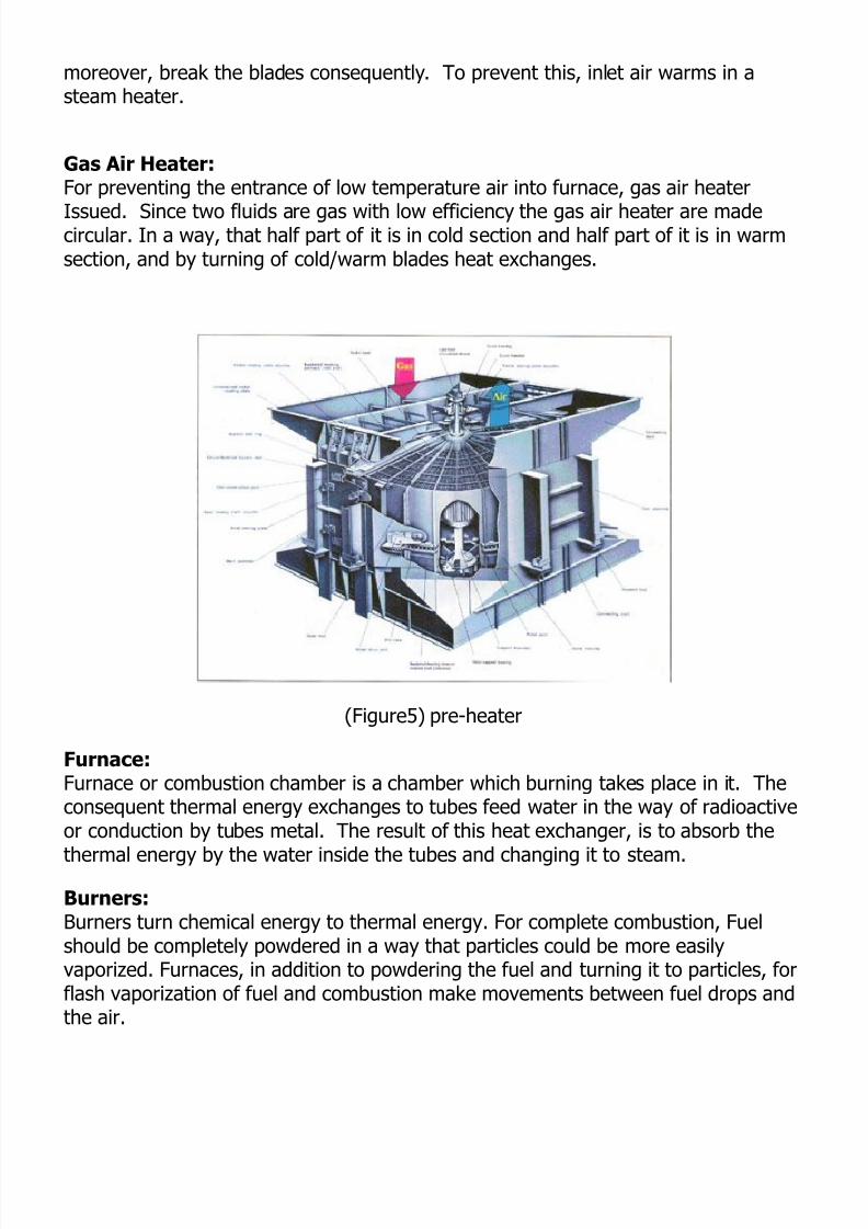
Gas Air Heater: For preventing the entrance of low temperature air into furnace, gas air heaterIssued. Since two fluids are gas with low efficiency the gas air heater are madecircular. In a way, that half part of it is in cold section and half part of it is in warmsection, and by turning of cold/warm blades heat exchanges.
(Figure5) pre-heater
Furnace: Furnace or combustion chamber is a chamber which burning takes place in it. Theconsequent thermal energy exchanges to tubes feed water in the way of radioactiveor conduction by tubes metal. The result of this heat exchanger, is to absorb thethermal energy by the water inside the tubes and changing it to steam.
Burners:Burners turn chemical energy to thermal energy. For complete combustion, Fuelshould be completely powdered in a way that particles could be more easilyvaporized. Furnaces, in addition to powdering the fuel and turning it to particles, forflash vaporization of fuel and combustion make movements between fuel drops andthe air.

Gas Recirculation Fan (G.R.F):Some parts of burnt gas fumes are added to inlet air for controlling the Nox andincreasing the thermal efficiency.By using G.R.F some percentage of outlet combustion products will be returned tofurnace to cover the outer surface of the tubes as a layer for preventing the tubesenergy absorption in radioactive from. More increase in molecules makes moreconvection inside the furnace. G.R.F is more efficient in low temperature, becausedecreases the radioactive energy absorption in one hand and prevents overheatingthe superheat when starting to work.
Controlling the temperature of outlet steam from super-heaters: A- Using De-Super-Heaters (Water Spray):Using water spray after primary super heater decreases the secondary super Heatersteam temperature. This system is necessary for boilers because of its speed andreliability. This system is planned in a way that in its real charge keeps some waterspray for the time of not having real temperature because of Carbon black formationinside the tubes.
B- Angular Change Of Furnaces:By changing the angle of furnaces, the amount of free energy in furnace of differentheights can be changed. Bringing down the furnace head, increases the producedsteam when reducing the steam temperature.
C- Using G. R. F:For controlling the steam temperature when starting to work, some amounts ofOutlet gases will be sent back to furnace by G.R.F.
Incinerator Boilers: Ever increasing production of garbage and inappropriate ways of gathering madethe thermal plasma process a proper method for burning the garbage.
Plasma: Plasma is one of material forms. For the first time Dr. Long Muyer an AmericanChemical physician scientist in 1929 called the ionized gas as plasma.It consists of a set of atoms, ions and electrons, which move freely. Electric andmagnetic fields will affect plasma.

Plasma System For Garbage Disposal: All plasma system has five main parts:1. Feeding part2. Combustion chamber3. Outlet gas processing unit4. Gathering solid products5. Lateral equipmentGarbage enters the feeding unit. Then in appropriate portions, it will be put intofurnace. Plasma gas, which is heated to near the sun heat, will be transferred togarbage. Plasma heat can be transferred in radioactive, convection and conductionforms garbage decomposes to raw and simple material by Pyrolisis method. Mainpart of outlet gases are hydrogen and carbon monoxides and acidic gases like HCIand h2 s. in plasma technology there is no need to oxygen and any oxygen reservesand its thermal out come is two to three times more the fossil fuels thermaloutcome.
Boiler planning and engineering department field of activities:- Planning of industrial and power plant natural circulation water tube boilerpackages with 20-t/hr capacity and more steam production based on customerdemand.-Technology transfer contract with IHI Company from Japan based onmanufacturing of water tube boilers with natural circulation burning with gas andfluid fuels as Per followings:- Package boilers from 20t/hr to 100t/hr capacity- Industrial boilers from 50t/hr to 350t/hr capacity- Power plant boilers from 390t/hr to 2200t/hr capacities-Technology transfer contract with Gadelius K.K for Langstorm pre-heaters- FW combination cycle
Different kinds of power plant, industrial and equipment manufactured in AzarAb Company
Boiler Type Choice:Water tube boilers are AzarAb main products and AzarAb is one of the greatestboiler manufactures in Middle East. We are able to manufacture different types ofwater tube boiler, from 20t/hr to 2000t/hr under the licensee of I.H.I form Japan.

(Figure 6)
1) Base Heating Power Plant Steam Boilers: This kind of boiler consists of a natural circulation drum, super heater andeconomizer. The air direction is toward furnace. This compound boiler consists offurnace and heat recovery zone. (Figure 7) AzarAb has installed in Shahid Rajai power plant a MW 250 model in which consistsof 12 furnaces in front wall and eight furnaces in back wall. Outlet gases pass twoparallel directions in which one of them consists of re-heaters and the other consistsof super-heaters.Heat gases passing the parallel directions exchange the heat to re-heaters andSuper heaters join each other, then pass the primary economizer and enter the airpre-heaters. Duper will control re-heaters, which are installed at the end of re-heaters outlet steam temperature from re-heater, and re-heater and Super-heaterdampers generator high changes are set in a way that outlet steam Temperatureremains stable. Advantages of controlling re-heater by dumber are as less consuming power, betterre-heater protection, and fast response to re-heater temperature changes.Re-heaters main duty is to increase outlet steam temperature from H.P. turbine.The boilers drum is located in upper part and along the width of boiler.Separating signs separates the water and steam mixture entering to drum from walltubes (risers).

(Figure 7)
Mentioned Boilers Specifications:Produced steam capacity 390 to 2200 t/hrPlanned pressure amount 150 to 2000 kg/cm2Its fuel bused on its facilities can be natural gas or mazout.
2- Stable Boilers (SN):These boilers under the I.H.I certificate are manufactured for industrial and Powerplant purposes. They are single drum non-heat-recovery, natural circulation andradioactive heat transfer .the used fuels can be natural gas mazout or gas oil.- Produced steam capacity 90 to 950 t/hr- Planned pressures amount: 80 to 150kg/cm2

(Figure 8)
3- Stable Boilers (SD):This kind of boilers because of their high quality and efficiency has special Situationbetween industrial and power plant boilers.With a stable structure, consist of two water and steam drums with naturalCirculation fluid, a large furnace for complete combustion and high temperaturecontrol super heaters.Boiler more specifications:Produced steam capacity 40 to 420 t/hrPlanned pressure amount 40 to 110 kg/cm2Maximum temperature 515 c (960 f)
4- Water Tube Boiler (SCM):For better maintenance, these boilers consist of two drums and heat exchange isdone by furnace in convection and radioactive ways.

(Figure 9)
Here the preheated water conducts to water and steam drum installed in top of theboiler and then goes to all tubes and pipes. Contrary to type 1, this boiler has noheat recovery system. Water walls with two or 2.5-inch outer diameters arecompletely welded for using in replacement units.For regulating the water level in drum, there are special signs under the usual Waterlevel. In this way, the dryness of the steam will be kept more than 99.5 Percent.BOILER MORE SPECIFICATION:
- Produced steam capacity: 5 to 35t/hr- Planned pressure amount: 10 to 25kg/m2Mazout is the used fuel.
5- Pre-Made Boilers (SC): Contrary to other boilers, these boilers will be transported and installed in the siteafter manufacturing and installing it in the workshop as a complete pre-mode unit.There are some limits in dimensions and weight of these boilers because of Trafficregulations.MORE SPECIFICATIONS:- Produced steams capacity 250 t/hr- Planned presser amount: 30 to 350 kg/cm2- Maximum temperature 48c (900 f)The used fuels are gas or gas oil and/or a mixture of both.

(Figure 9)
Boilers Lateral Equipment : 1- Gas and air canals2- Gas and air regulating valves3- Gas and air expasile Canal openings4- Inlet air preheating by steam and water AzarAb manufactured all these equipment.
Electricity industry is a basic industry and all other industries and activities aredirectly and indirectly are relative to it. So investing on it is necessary. Countriesprovide their needed energy from different ways such as fossil, atomic, water,natural gas, coal, and geothermal fuels. From whole of useful used energy, somepart of it will be converted to useful energy and a part of it will be wasted. Fromaspect of producing the electricity hydropower, plants are divided to:- Large hydropower plants (LHP) (more than 100mw capacity)- Small hydro power plants (SHP) (between 1 to 100mw capacity)- Mini hydro power plants (lower than 1mw capacity)
Small hydro power plants are in two forms:- Low head small hydro power plants- High head small hydro power plants as a general highhead hydro power plants are cheaper than the low head

ones, due to the used turbines.In large hydro power plants the installation place of turbine is on dam installations,water conducts toward turbine by a canal and turns the runner that is connected toturbines shaft and turning the shaft generates electricity.
Hydropower Plants Department and Factory Equipment:Based on our country's developing policies and localizing the basic industrytechnology, departments’ goals are de fined in forms of GC and EPC. Based on our20 years of experiences from abroad training courses and using our uniqueequipment, the department and company has capabilities in making power plantprecise parts, planning, finance and industrial consultant commerce, makingengineering, erection, commissioning and project management in manufacturinghydro power plants, Francis, Kaplan and butterfly valves.Based on our policy, AzarAb has done the engineering construction or left themanufacturing of karun1, Karun2, Karun3, Karun4 or Masjed Soleiman, karkhehpower plant and factories equipment to other regional companies and by distributingthe work among the regional companies has performed a significant role.In addition to active participating in domestic industries, this department has beenpresent in international markets such as China, Austria, and Belarus.In addition, this department has made much effort on continuing the establishmentof Occupation Health and Safety Management System OHSAS 18001.Non-destructive test on all under process parts takes place in hydro power plantsand factory equipment department based on most modern methods.The tests performance guide starts from entering the raw material to our RawMaterial Receipt Department by using VT, DT, and UT tests.
In forming unit, metal sheets up to 220mm thickness will be rolled and pipes up to52" diameter will be bent, performing DT, VT, PT, and VT tests.In assembling line, precise parts will be assembled in X, Y, Z coordinates and byusing digital precise measuring and calibrated tools (Camera and control bymachine).In machining workshop, light and heavy parts up to 200 ton with 12m length, 5mwidth, 12m diameter, and 6m height are being work with using DT test with hecto-millimeter tolerance.In welding field based on ASTM, ASME, DIN and other international standards alongwith VT, DT, PT, MT, UT and RT tests, the qualified methods are being used.On thermal operation, based on our capability and factory powerful thermaloperation equipment, this department issues the stress – relief, aniline and returnguides, and regarding the operation has quiet assessment through by QualityControl Department.Following the first, second and third schedule of the country's economicaldevelopment, AzarAb has a noteworthy role in the national goals by participating in

manufacturing the essential machinery and equipments of mother industries.Client's satisfaction by on time doing the order and standard quality and leastexpenses in compare with foreign manufacturer is one this industries company longterm schedules. All attempts and tries of the management and staff would be widely offered to reachto these objectives.Based on our capabilities and obtained experiences during participating inperforming the country's heavy projects and regarding the market potential andcurrent fortunes and threats, market's quality and quantity development, AzarAb hasstarted manufacturing of Francis type hydro turbines equipment from 1985 asfollow:1- Karun 1 hydro-turbine in four units with 250MW power output2- Karun 3 hydro-turbine in eight units with 250MW power output3- Karkheh hydro-turbine in three units with 133MW power output4- Masjed Soleiman hydropower in four units with 250MW Power output5- Masjed Soleiman developing plan hydropower in four units with 250MW poweroutput6- Gotvand hydro-turbine in four units with 250MW power output7- Karun 4 hydro-turbine in four units with 250MW power output8- Siah Bishe hydro-turbine in four units with 250MW power output9- Seimare hydro-turbines in three units with 163MW power output
Manufacturing of high capacity hydro-turbines is performed for the first time in Iran. AzarAb in cooperation with FARAB Company based on its strong professionalpotential both in software and hardware capabilities could solve all problems anddifficulties and now produces the high quality products. For instance, the moldingof heavy equipments was one of the main problems in the way of these projectsand fortunately, now we have successfully solved all of these problems with the helpand cooperation of AzarAb's experts.We offer our thanks to Mr. Mahnama and Mr. Karbalai current managing directors ofFARAB and AzarAb companies for their wide attempts and also Mr. Haj Rasoulianthe chairman of the board of FARAB for his guidance.By choosing 30 direct contractors and 50 indirect contractors in the fields of moldingand forging under the AzarAb monitoring the manufacturing operation of the projectstarted to perform. After the confirmation of plans and documents by employeragents some portion of the equipment were sent to site and installed. Accordingthe most experts' comments, these equipments in compare with the foreign oneshave better quality.Now four units of Masjed Soleiman developing plan, Karun 4, Gotvand and SiahBishe hydro-turbines equipment manufacturing process have come to conclude with VOITH from Austria, and Seimare project with ALSTOM from France, in which mainpart of equipment is delivered to VOITH's agency in the least possible time and

manufacturing of the rest equipment is still continued.Draft tube elbow from Seimare hydro-turbine project is delivered to ALSTOM too. AzarAb has confirmed about 60-milliard Rials investment in water projects, hasperformed about 90% of the project, and now is generating electricity.In addition to hardware investment, AzarAb has seriously followed the technologytransfer and has made a contract with L.M.Z, in which the first phase of the contractfor planning and manufacturing of butterfly valves has successfully ended. In anyway AzarAb activity in hydropower plants field focuses on two parts:1. Planning and manufacturing of butterfly valves2- Planning and manufacturing of hydro-turbines
Butterfly Valves:Butterfly valves is used to open and close the inter water main direction, whichincludes four main parts as case, disk, upper and lower pipes and two hydraulic jacks. Its diameter and weight is about 5.3m and 272t, which is from the biggestones in all over the world and just a few countries are able to manufacture it.Its case weighs about 70t and each one of molded parts is about 11~15t, withabout 800mm thickness.Used sheets thickness is from approximately 30mm to130mm the its joints are performed with usage of verymodern technology and its manufacturing processinvolves cutting, welding, thermal operation, precisemachining, hydrostatic test, leakage test, and systemoperation test. Regarding its huge dimension, somespecial equipment is installed in AzarAb. Now theoperation of molding, construct, machining, hydrostatic test, and leakage test issuccessfully ended and we are witness of its operation in hydro power plants.
Hydro-Turbines:Spiral Case:Its main duty is to distribute the inlet fluid equally to stay ring in a way that inletfluid speed is stable to prevent the chock of fluid movement non-symmetry.Geometrical shape of spiral case is like a spiral and the curve causes to reduce thefluid pressure loss to its smallest amount. The spiral case weighs about 170 tonsand is made of high-resistance steel alloy sheets (62 U, S460N, P355) with 24 to60mm thickness.Due to its curve and non-symmetric it is formed byspecial rolling operation that needs high technicalknowledge and experience and joint to each other bywelding operation. Then its complete pre-montage –regarding the dimension control and planning dataapproval- is perform and tested under 34.8bar water.

Since manufacturing of spiral case parts regarding the algebraic form and highprecise need much sensitivity, so RT and UT tests will test all welded directionsaccording the standard.
Distributor:Its main duty is conducting the inlet water to runner blades and a dynamicassembly. This assembly consists of near five thousands small and big parts andare in mechanical conformity with each other, which are mode of antirust martenzitisteel which is used in industrial process such as molding,cutting, welding, machining and thermal operationaccording the international standards and weight about160 ton.Distributors move by two hydraulic jacks with 40barpressure, which is manufactured in AzarAb. AzarAb Company is now based on its scientific knowledgeis among the world's famous companies such as VOITH, ALSTOM, H.E.C, and GE.
Wicket Gate:Wicket gate plays an important role in hydropower plants. Wicket gate increasesturbine revolution and after paralleling with net, increases the turbine load.Changing in turning place of this part causes the change in flow rate of turbinerunner. Wicket gate conducts the water flow into runner. In this case, the angle ofentering water to runner is too important and plays animportant role in efficiency and reducing cavitations.Because of nature of flowing water in turbine direction,sandy parcels and impure material, and cavitationscauses friction and corrosion in wicket gates. So after atime depend on the condition of operation and the waterand grease material, the journal place and the sealingon the wicket will corrode.In this case, manufacturing and and/or purchasing a new wicket gate is tooexpensive and needs much time, so AzarAb tries to use certain economicalmaintenance methods and makes the start to power plants easy.Based on following applicable method wicket gates can be ready to perform in ashort time: total wicket gate cleaning, quality control in all levels repairing theruined parts, cleaning the welding surfaces, thermal operation for stress – relief,make the repaired surfaces to standard sizes by lathe operation, doing chromecampsite coating in friction surfaces and wicket gates seats.The machining operation of wicket gate is too important in a way that shaft andseat angle of the sealing should be in the same direction.

Runner:Runners change the fluid motion moment and make the generator to turn. Sincethe static pressure of the runner blades is equal, so the pressure does nothing.The aerodynamic shape of the blades is so that the pressure turns to kinetic energyalong the blade so the static pressure in blades both sides are equal. Thus, thestatic pressure in blades outlet is less than its inlet. As the turbine is Francis type, the radical inlet flow and intheThe fluid flow on the blades should be symmetrical, toprevent the chock on turbine shaft.Runner is one of the basic turbine parts so blades shouldbe resistant against cast frictional stresses andcavitations. Its main parts such as blades, crowns, bandsare made of antirust steel and in molding method.
Welding these stainless steel parts needs special technology and equipment inwhich AzarAb is equipped with the best ones. Regarding their dynamically, specialsensitive and care is applied in their manufacturing process.
Draft Tube Elbow: Since the outlet flow contains kinetic energy and thepressure in runner outlet is too low to prevent cavitationsand energy loss a make use of unloading pipe is essentialthat its aerodynamic shape is acquired by the model anddimensional analysis.Each unloading pipe consists of 16 semi cone segmentsand weighs 78 tons, which is manufactured by rolling andwelding operations with essential technical knowledgeand experience.
Servomotor:To open and close the butterfly valves and turbine moveable blades for regulatingthe inlet water to runner, two 40 and 60 bar hydraulic jacks are used. As the openand closing time should in a special period, the precise of manufacturing is toohigh. For example, the inner side of the cylinder should be sangzani to be assuredof essential surface safi. In addition, the hydrostatic, leakage, and performancetests for controlling the process of the manufacturing, resistance, and planningverification would be performed.

Type of boilers
This section describes the various types of Boilers: Fire tube boiler,Water tube boiler, Packaged boiler, Fluidized Bed Combustion Boiler,tmospheric Fluidized Bed Combustion Boiler, Pressurized Fluidized
Bed Combustion Boiler, Circulating Fluidized Bed Combustion Boiler,Stoker Fired Boiler, Pulverized Fuel Boiler, Waste Heat Boiler andThermic Fluid Heater.
Fire Tube Boiler
In fire tube boiler, hot gases passthrough the tubes and boiler feedwater in the shell side is converted intosteam. Fire tube boilers are generallyused for relatively small steamcapacities and low to medium steampressures. As a guideline, fire tubeboilers are competitive for steam ratesup to 12,000 kg/hour and pressures up to 18 kg/cm2. Fire tube boilersare available for operation with oil, gas or solid fuels. For economicreasons, most fire tube boilers are nowadays of “packaged”construction (i.e. manufacturers shop erected) for all fuels.
Water Tube Boiler
Fig: Simple Diagram ofWater Tube Boiler
Reference:http://www.yourdictionary.com/

In water tube boiler, boiler feed waterflows through the tubes and enters
the boiler drum. The circulated water is heated by the combustiongases and converted into steam at the vapour space in the drum.These boilers are selected when the steam demand as well as steampressure requirements are high as in the case of process cum powerboiler / power boilers.
Most modern water boiler tube designs are within the capacity range4,500 – 120,000 kg/hour of steam, at very high pressures. Manywater tube boilers nowadays are of “packaged” construction if oil and /or gas are to be used as fuel. Solid fuel fired water tube designs areavailable but packaged designs are less common.
The features of water tube boilers are:
Forced, induced and balanced draft provisions help to improvecombustion efficiency.
Less tolerance for water quality calls for water treatment plant. Higher thermal efficiency levels are possible
Packaged Boiler
The packaged boiler is so called because it comes as a completepackage. Once delivered to site, it requires only the steam, water pipework, fuel supply and electrical connections to be made for it tobecome operational. Package boilers are generally of shell type withfire tube design so as to achieve high heat transfer rates by bothradiation and convection.
The features of package boilers are:
Small combustion space and highheat release rate resulting infaster evaporation.
Large number of small diametertubes leading to good convectiveheat transfer.
Forced or induced draft systemsresulting in good combustionefficiency.
Number of passes resulting in better overall heat transfer.
Higher thermal efficiency levels compared with other boilers.
images/ahd/jpg/A4boiler.jpg

These boilers are classified based on the number of passes - thenumber of times the hot combustion gases pass through the boiler.The combustion chamber is taken, as the first pass after which theremay be one, two or three sets of fire-tubes. The most common boilerof this class is a three-pass unit with two sets of fire-tubes and withthe exhaust gases exiting through the rear of the boiler.
Fluidized Bed Combustion (FBC) Boiler
Fluidized bed combustion (FBC) has emerged as a viable alternativeand has significant advantages over conventional firing system andoffers multiple benefits – compact boiler design, fuel flexibility, highercombustion efficiency and reduced emission of noxious pollutants suchas SOx and NOx. The fuels burnt in these boilers include coal, washeryrejects, rice husk, bagasse & other agricultural wastes. The fluidizedbed boilers have a wide capacity range- 0.5 T/hr to over 100 T/hr.
When an evenly distributed air or gas is passed upward through afinely divided bed of solid particles such as sand supported on a finemesh, the particles are undisturbed at low velocity. As air velocity isgradually increased, a stage is reached when the individual particlesare suspended in the air stream – the bed is called “fluidized”.
With further increase in air velocity, there is bubble formation,vigorous turbulence, rapid mixing and formation of dense defined bedsurface. The bed of solid particles exhibits the properties of a boilingliquid and assumes the appearance of a fluid – “bubbling fluidizedbed”.
If sand particles in a fluidized state is heated to the ignitiontemperatures of coal, and coal is injected continuously into the bed,the coal will burn rapidly and bed attains a uniform temperature. Thefluidized bed combustion (FBC) takes place at about 840 OC to 950OC. Since this temperature is much below the ash fusion temperature,melting of ash and associated problems are avoided.
The lower combustion temperature is achieved because of highcoefficient of heat transfer due to rapid mixing in the fluidized bed andeffective extraction of heat from the bed through in-bed heat transfertubes and walls of the bed. The gas velocity is maintained betweenminimum fluidisation velocity and particle entrainment velocity. Thisensures stable operation of the bed and avoids particle entrainment in

the gas stream.
Atmospheric Fluidized Bed Combustion (AFBC) Boiler
Most operational boiler of this type is of the Atmospheric Fluidized BedCombustion. (AFBC). This involves little more than adding a fluidizedbed combustor to a conventional shell boiler. Such systems havesimilarly being installed in conjunction with conventional water tubeboiler.
Coal is crushed to a size of 1 – 10 mm depending on the rank of coal,type of fuel fed to the combustion chamber. The atmospheric air,which acts as both the fluidization and combustion air, is delivered at apressure, after being preheated by the exhaust fuel gases. The in-bedtubes carrying water generally act as the evaporator. The gaseousproducts of combustion pass over the super heater sections of theboiler flow past the economizer, the dust collectors and the airpreheater before being exhausted to atmosphere.
Pressurized Fluidized Bed Combustion (PFBC) Boiler
In Pressurized Fluidized Bed Combustion (PFBC) type, a compressorsupplies the Forced Draft (FD) air and the combustor is a pressurevessel. The heat release rate in the bed is proportional to the bedpressure and hence a deep bed is used to extract large amount ofheat. This will improve the combustion efficiency and sulphur dioxideabsorption in the bed. The steam isgenerated in the two tube bundles, one inthe bed and one above it. Hot flue gasesdrive a power generating gas turbine. ThePFBC system can be used for cogeneration(steam and electricity) or combined cyclepowergeneration. The combined cycleoperation (gas turbine & steam turbine)improves the overall conversion efficiencyby 5 to 8%.
Atmospheric Circulating Fluidized BedCombustion Boilers (CFBC)
In a circulating system the bed parametersare so maintained as to promote solidselutriation from the bed. They are lifted in a

relatively dilute phase in a solids riser, and a down-comer with acyclone provides a return path for the solids. There are no steamgeneration tubes immersed in the bed. Generation and super heatingof steam takes place in the convection section, water walls, at the exitof the riser.
CFBC boilers are generally more economical than AFBC boilers forindustrial application requiring more than 75 – 100 T/hr of steam. Forlarge units, the taller furnace characteristics of CFBC boilers offersbetter space utilization, greater fuel particle and sorbent residencetime for efficient combustion and SO2 capture, and easier applicationof staged combustion techniques for NOx control than AFBC steamgenerators.
Stoker Fired Boilers
Stokers are classified according to the method of feeding fuel to thefurnace and by the type of grate. The main classifications are spreader
stoker and chain-gate or traveling-gatestoker.
Spreader Stokers
Spreader stokers utilize a combination ofsuspension burning and grate burning. Thecoal is continually fed into the furnace abovea burning bed of coal. The coal fines areburned in suspension; the larger particlesfall to the grate, where they are burned in athin, fast-burning coal bed. This method of
firing provides good flexibility to meet load fluctuations, since ignitionis almost instantaneous when firing rate is increased. Due to this, thespreader stoker is favored over other types of stokers in manyindustrial applications.
Chain-grate or Traveling-grate Stoker

Coal is fed onto one end of a moving steel grate. As grate moves alongthe length of the furnace, the coal burns before dropping off at the endas ash. Some degree of skill is required,particularly when setting up the grate, airdampers and baffles, to ensure cleancombustion leaving the minimum of unburntcarbon in the ash.
The coal-feed hopper runs along the entirecoal-feed end of the furnace. A coal gate isused to control the rate at which coal is fedinto the furnace by controlling the thicknessof the fuel bed. Coal must be uniform in sizeas large lumps will not burn out completelyby the time they reach the end of the grate.
Pulverized Fuel Boiler
Most coal-fired power station boilers use pulverized coal, and many ofthe larger industrial water-tube boilers also use this pulverized fuel.This technology is well developed, and there are thousands of unitsaround the world, accounting for well over 90% of coal-fired capacity.
The coal is ground (pulverized) to a fine powder, so that less than 2%is +300 micro meter (μm) and 70-75% is below 75 microns, for abituminous coal. It should be noted that too fine a powder is wastefulof grinding mill power. On the other hand, too coarse a powder doesnot burn completely in the combustion chamber and results in higher
unburnt losses.The pulverized coal is blown with part of thecombustion air into the boiler plant through aseries of burner nozzles. Secondary andtertiary air may also be added. Combustiontakes place at temperatures from 1300-1700°C, depending largely on coal grade.Particle residence time in the boiler is typically2 to 5 seconds, and the particles must besmall enough for complete combustion tohave taken place during this time.
This system has many advantages such as ability to fire varyingquality of coal, quick responses to changes in load, use of high pre-
heat air temperatures etc.
One of the most popular systems for firing pulverized coal is thetangential firing using four burners corner to corner to create a fireballat the center of the furnace.
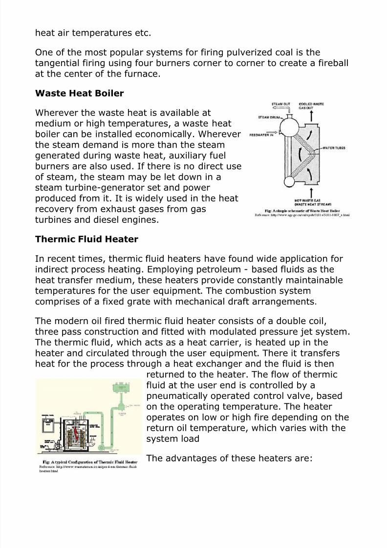
Waste Heat Boiler
Wherever the waste heat is available atmedium or high temperatures, a waste heatboiler can be installed economically. Whereverthe steam demand is more than the steamgenerated during waste heat, auxiliary fuelburners are also used. If there is no direct useof steam, the steam may be let down in asteam turbine-generator set and powerproduced from it. It is widely used in the heatrecovery from exhaust gases from gasturbines and diesel engines.
Thermic Fluid Heater
In recent times, thermic fluid heaters have found wide application forindirect process heating. Employing petroleum - based fluids as theheat transfer medium, these heaters provide constantly maintainabletemperatures for the user equipment. The combustion systemcomprises of a fixed grate with mechanical draft arrangements.
The modern oil fired thermic fluid heater consists of a double coil,three pass construction and fitted with modulated pressure jet system.The thermic fluid, which acts as a heat carrier, is heated up in theheater and circulated through the user equipment. There it transfersheat for the process through a heat exchanger and the fluid is then
returned to the heater. The flow of thermicfluid at the user end is controlled by apneumatically operated control valve, basedon the operating temperature. The heateroperates on low or high fire depending on thereturn oil temperature, which varies with thesystem load
The advantages of these heaters are:

Closed cycle operation with minimum losses as compared tosteam boilers.
Non-Pressurized system operation even for temperatures around250 0c as against 40 kg/cm2 steam pressure requirement in asimilar steam system.
Automatic control settings, which offer operational flexibility. Good thermal efficiencies as losses due to blow down, condensate
drain and flash steam do not exist in a thermic fluid heatersystem.
The overall economics of the thermic fluid heater will depend upon thespecific application and reference basis. Coal fired thermic fluidheaters with a thermal efficiency range of 55-65% may comparefavorably with most boilers. Incorporation of heat recovery devices inthe flue gas path enhances the thermal efficiency levels further.
Steam Locomotive Operation
The latest reviewed version was checked on 28 May 2013. There
are template/file changes awaiting review.
A Wikibookian believes this page should be split into smaller
pages with a narrower subtopic.
You can help by splitting this big page into smaller ones. Please
make sure to follow the naming policy. Dividing books into smaller
sections can provide more focus and allow each one to do one thing
well, which benefits everyone.
You can ask for help in dividing this book in the assistance reading
room.
This book is an operators manual for the operation of functional steam
locomotives. The terms and procedures described here will enable a person to
safely operate a 19th or 20th century steam locomotive well into the future.
To hostle, fire, or engineer a locomotive effectively, efficiently, and safely, a
person should have a good understanding of the construction and the physics
that go into a steam engine to produce locomotion as well as an understanding
of normal operating techniques.
Contents
[hide]

1 Locomotive Construction and Parts
o 1.1 The Boiler
o 1.2 Combustion Chamber
o 1.3 Effect of Heating, Cooling, and Low Water
o 1.4 Temperatures of Steam and Water
2 The steam circuit
3 The Crew
o 3.1 Hostler
o 3.2 Fireman
o 3.3 Engineer
4 Firing
o 4.1 General Practices
o 4.2 Fire less Locomotives
o 4.3 Wood Burning Locomotives
o 4.4 Oil Burning Locomotives
5 References
Locomotive Construction and Parts[edit]
The Boiler [edit]
A common later (1940s) boiler design was the radial stay extended wagon top
type of locomotive boiler, which consists of an oblong box with a circular top
made of steel plating, connected to a cylindrical part which is commonly known
as the barrel of the boiler. That part of the boiler enclosing the firebox is known
as the outer casing, or shell. The firebox corresponds in shape to the back end
and sides of the outer casing or shell, a space being provided between the
firebox sheets and those of the outer casing which provides for the firebox being
surrounded by water. The front, or cylindrical part of the boiler encloses the flues
which are secured at the front to the front flue sheet and at the back to the inner
or firebox flue sheet.
This arrangement provides that all parts of the firebox, as well as the flues are
completely surrounded by water, and it also provides that when fuel is burned in
the firebox, the heat will be transmitted by the flues and firebox plates to the
water; the unused gasses and smoke having free passage from the firebox
through the flues to the smoke box and smoke stack.
The smoke box is formed by extending the cylindrical part of the boiler beyond
the front flue sheet. The boiler shell is provided with a steam dome on top of the
shell which forms a chamber where steam may collect and free itself from the

water in the boiler before passing through the throttle valve to the cylinders.
The flues in a locomotive boiler are known as fire tubes, because the heat
passes through them, while the arch tubes, of which there are usually four in
each firebox are called "water tubes" because the fire is on the outside, and the
water passes through them.
The firebox sheets and flues constitute what is known as the heating surface. In
addition to this heating surface there is additional, or superheater heating surface
in many boilers, which superheats the steam after it leaves the boiler and while it
is passing from the boiler to the cylinders. Comparing the flue heating area with
that of the area of the firebox plates shows that the plate heating surface equals
only 5% of the flue heating surface, but the firebox heating surface generates
about 40% of the steam. This fact should be remembered.
In the locomotive boiler a large number of small flues are provided instead of a
few large flues, in order that the heat and gasses passing from the firebox to the
smoke box will be split up and come into contact with a larger flue surface. If
large flues were used, great quantities of heat would pass through the center of
the flues without coming into contact with the surface of the flue, such heat would
pass away and be lost. A large number of small tubes also provides for the heat
being more evenly distributed through the boiler shell water space. The small flue
can be made of thinner material, which permits the heat to be more easily
transmitted to the water which surrounds the flues. In the extended wagon top
type of locomotive boiler, the back part, or outer shell, is considerably larger in
diameter than the front section, or cylindrical part; while the straight type of boiler
has the outer shell and cylindrical part of practically the same diameter. The
extended wagon top type therefore allows more steam and water space, and
gives superior performance in foaming water conditions.
Locomotive boilers are made entirely of steel, except stay-bolts and stays, which
are of iron. The crown sheet is supported by what are called radial stays,
reaching from the crown sheet to the exterior wrapper sheet.
There are three common designs of fireboxes in general use. The narrow, deep
firebox, which is between the frames and extends below the top frame rails. The
semi-wide shallow firebox which rests on top of the frames and extends to the
outside edges of the frame rails, and the wide firebox type having a firebox wider
than the frames and extending outside the frame rails on both sides, and resting
on top of the frame rails, or expansion brackets which are secured to the top of
the frames.
Combustion Chamber [edit]

The combustion chamber for large locomotives was originally introduced for the
purpose that its name implies, of providing increased firebox area for combustion
purposes. As locomotives grew larger and the wheel base longer, it then became
a question of limiting the length of flues. It was found that when flues were more
than 21 or 22 feet long, there was considerable more trouble in respect to
leakage and in order to keep the flues within those limits of length it was
necessary to lengthen out the firebox, which was done by extending the flue area
into the boiler.
There is also an advantage of the combustion chamber, in addition to allowing
shorter flues, the heating surface of the firebox sheets composing the
combustion chamber is vastly more efficint than the increased length of flues
would be if the combustion chamber was not used.
The combustion chamber also serves to protect the ends of the tubes from cold
air which comes up through the grates at the front end of the firebox, in addition
to providing a long flameway for the burning gases, which is particularly desirable
with oil, or coal, having a large percentage of volatile matter.
Effect of Heating, Cooling, and Low Water [edit]
When the crown sheet or firebox sheets are not covered with water, they become
overheated very quickly with a hot fire in the firebox. If for any reason water is not
maintained over the crown sheet, and the sheet becomes overheated, the fire
must be put out or deadened at once, and under no circumstances should cold
water be forced into the boiler. The boiler should be cooled down before any
attempt is made to refill it, because forcing cold water into the boiler when it is
very hot produces sudden changes in temperature of the various parts of the
sheets and sets up destructive strains.
The prevention of destructive strains and stresses, or reducing their amplitude
should interest all who have to do with the upkeep of the locomotive. In order to
bring out clearly and simply the cause of destructive stresses, it should fully be
understood that the contraction or expansion of a body of metal when changes of
temperature occur is irresistible. A firebox sheet expanding or contracting as
a result of a change in temperature cannot be restrained. It is certain to find
relief in some direction, either by self destruction or destroying the obstacle
opposing its movement.
The life of a locomotive boiler or firebox is dependent largely upon the care which
it receives while in service. It is not possible in the operation of a locomotive to
avoid all strains and stresses, but it is possible, practical, and beneficial to
reduce the frequency of the stresses and also their amplitude. In other words, if

by any means the severity of the strains is reduced even though their frequency
be increased, the period between failures will be prolonged, the time between
repairs and the life of fireboxes and boilers will be lengthened.
Figure 3, which is a diagram of the boiler shown in Figure 1, illustrates the action
of metal when heating and cooling takes place. It will be noted that the boiler is
divided into sections. After steam is generated in the boiler to 200lbs per square
inch, it is found that the boiler has expanded nearly one inch, which
demonstrates that the metal expands as heating takes place and that when the
boiler cools the metal contracts. Expansion and contraction of the metals thus
sets up strains and stresses at various parts in the boiler, and it is important that
as these strains are developed that they be developed slowly, in order that the
effect of heating or cooling will be distributed throughout the boiler so that the
expansion or contraction will be as uniform as possible throughout all its parts.
Temperatures of Steam and Water [edit]
Operating a water injector or water pump while locomotive is standing causes
more frequent and greater inequality of temperatures throughout the boiler and
the development of more destructive stresses than any other cause. To illustrate:
Temperature of the steam in a locomotive boiler at 190 psi is 383 degrees
Fahrenheit (195 degrees Centigrade). This is also the temperature of the water
at that steam pressure. When an injector is operated, the water passing through
the injector on its way to the boiler is heated from 160 to 200 degrees F (71 to 93
degrees C). It is therefore from 183 to 223 degrees F (102-124 deg C) cooler
than the water within the boiler. The water from the injector being cooler is
heavier than the higher temperature water in the boiler, and on entering the
boiler must take a downward course and continue downward until it reaches the
lowest part. The weight of a cubic foot of water as it enters the boiler from the
injectors is 60 1/8 pounds, while a cubic foot of water at 190 psi steam pressure,
or 383 degrees Fahrenheit, is 54 1/4 pounds, or 9% lighter than the water at 200
degrees delivered into the boiler from the injector. This difference of weight
makes it clear why the cooler and heavier water seeks the lower levels and
displaces the hotter, lighter water.
Table Showing Temperatures of Steam at Different Pressures
Boiling point 212 F
100.0 C
100 psi 337.8 F
169.9 C

160 psi 370.6 F
188.1 C
180 psi 379.5 F
193.1 C
200 psi 387.8 F
197.7 C
220 psi 395.6 F
202.0 C
250 psi 406 F
207.8 C
300 psi 421.7 F
216.5 C
-Quick reference to Water boiling point (Not Steam Temp) at different pressures-
The boiling point of water raises 3 degrees F per each pound of square inch
pressure added. For example: at sea level, water will boil at 212 degrees F (100
deg C). +1 PSI over sea level it will raise the boiling point 3 degrees F, to 215
degrees F (1.7 deg C, to 101.7 deg C). At +5 PSI over sea level the boiling point
of water will be 227 degrees F (108.3 deg C). And so on. This is why directions
for boiling noodles and baking goods at high altitudes require longer cook times,
and/or more water added to mixture.
The steam circuit[edit]
The Crew[edit]
Hostler [edit]
The hostler prepares an engine each day for service. This usually includes
starting the fire, greasing and oiling all lubrication points on a steam locomotive.
This was traditionally the starting point for a person coming onto the engine crew.

Additonally, Hostlers service locomotives with fuel and water, sand and
lubricants and assure that all required tools and flagging equipment are provided
on the locomotive. The firebox is cleaned or banked as necessary upon arrival at
the locomotive.
Fireman[edit]
The fireman maintains the steam pressure in a locomotive boiler. This is
accomplished through careful regulation of the fire, and by regular addition of
water to the boiler. Water is added through the use of an injector or feed water
pump. In the absence of an Engineer, he will be responsible for the safety and
security of the locomotive. Locomotive Firemen will not operate locomotives
unless under the direct supervision of a qualified Engineer.
Engineer [edit]
The engineer is responsible for ensuring that the engine is fit for operation before
and during any movement of the locomotive. The engineer is responsible for its
over the road upkeep, oiling and proper operation of the locomotive to be most
fuel efficient and easy on the machinery. The engineer controls the operation of
the locomotive but the conductor controls the movement of the train, and both
are responsible for its safe operation. The steam whistle, headlight, throttle, air
brakes, reverse lever, and fireman are usually under the direct control of the
engineer.
Firing[edit]
Firing involves caring for the boiler, and making sure there is always sufficient
steam for the engineer to use. When proficient, a fireman should concentrate on
efficient operation to conserve fuel, water and extend the life of the engine. This
is especially important in the 21st century as working steam engines are rare and
often in precarious financial situations.
General Practices[edit]
The boiler of a locomotive is made of a steel alloy and holds thousands of
gallons of water. The boiler must be treated with care at all times, as it must
withstand tremendous amounts of heat, pressure and vibration. The fireman
should take care to minimize the thermal stresses placed on the boiler when
safety permits.
Fire less Locomotives[edit]
Fire less locomotives generally used a tank (in place of a boiler and firebox) filled
with super heated water that flashed into steam as the pressure from working
existing steam dropped the pressure (refer to pressure table above). Fire less

locomotives were tied to operating in an area where they could obtain water
heated higher than the boiling point while a fire was undesirable for safety
reasons. They were used mostly in industries or a group of industries, and due to
this limitation were not common for moving trains on main lines. They were
replaced by explosion proof diesel or electric locomotives. There are no
references to currently operating fire less locomotives found by this author.
Wood Burning Locomotives[edit]
Wood burning locomotives fell into disfavor in the United States once expansion
into the western plain states began, chiefly because of the generally lower
amount of thermal energy wood locomotives offered from the fuel, and the
scarcity of forests in the plain states.
Oil Burning Locomotives[edit]
Oil burning locomotives in the steam era mainly used "Bunker C" fuel oil. (Bunker
C is also known as Type 6 or Number 6.)[1] While some preserved steam
locomotives of today (circa 2005) still use Bunker C, most have switched to
various alternative fuels as Bunker C can be difficult to locate, transport, and
store. Alternatives include Number 4 fuel oil, kerosene or diesel oil (and
sometimes a mixture of diesel/kerosene), others employ used motor oil.
Regardless of the kind of oil used, most locomotives store the fuel in a tank on
the tender. The oil tank is equipped with steam heat coils to heat the fuel before
combustion. This is done to keep the oil viscosity such that the oil can flow freely
to the combustion chamber. Bunker C fuel oil is very thick and difficult to use
without pre-heating.
The fire in an oil burning locomotive is controled with two valves: The fuel valve,
which controls the flow of oil to the atomizer, and the atomizer valve, which
controls the steam to force the oil into small droplets for burning.
The fireman must control the amount of steam, oil, and air in the combustion
chamber to produce the most effecient fire to boil the water. The fireman
observes the color of the smoke emitted from the smoke stack to determine what
the fire needs. Thick, foul smelling black smoke indicates that the fire is not
burning correctly due to too much fuel oil. The fireman can increase the draft of
air using dampers and the blower or reduce the amount of oil to the burner. Blue
smoke indicates too much steam is being admitted to the atomizer, and he must
reduce the steam pressure. A light grey smoke indicates proper adjustment,
while no smoke at all means the fire is too light and should be increased.
It is worthy to note that under some circumstances, the fireman can cause a
series of hollow booms or small explosions though mis-adjustment of the fire. If
one were to be watching with the firedoors open at such a time, one would see
that the flame is being ripped away from the burner and into the flues. This also
can cause heavy amounts of soot to be deposited in the flue, reducing the
effeciency of the boiler. The soot can be cleaned by throwing sand into the
combustion chamber, but this causes undesireable wear to the flues and any
superheaters.
Super critical boilers
supper critical is simply the point above which a two phase mixture doesnot exist. If we start with water at room temperature and above the criticalpressure it is still water and acts as a fluid. Above the critical pressure aswe heat the water we will simply not goto a phase change. There is still asaturation line so to speak. If you look at the density change withtemperature you find that the saturation can be extended along a line werethere is a significant density change rate with temperature. I don't know ifanybody else has noticied this though. At any rate below the criticalpressure when you heat water you reach a point were adding heat stopsrasing the temperature and the heat goes into effecting a change of phasefrom liquid to water. The amount of BTUs it takes to change liquid to vaporis decreasing as you increase the pressure until you reach the criticalpoint. At the critical point the heat it takes ti effect a change of phasebecomes zero. Loot at the chart on my web page. There is a 3D chart ofpressure temperature and enthalpy(heat content). That chart does not go tothe critical point but can clearly see a wall of constant temperature alongthe saturation line. The height of the wall is the heat of vaporazation andyou can see that it's height it deminishing as the pressure is increassing.Ot just keeps deminishing right up to the critical point. You might also notethat the top of the saturation wall is almost constant and that is the heatcontent of the liquid water increassing with pressure along the saturationline that is reducing the wall's height. If thoes charts went to the criticalpoint that saturation wall would reduce town to zero height. And above thecritical pressure it would not exist.I think in a super ctitical boiler your circulation rate is not importantbecause there is no bubble formation or evaporation and the there is onlyone condition through out the boiler. The bubbles / vapor are the robbersof heat transfer and without them the tube wall is always wet for maximumheat conduction. The evaporation zone is fairly short and the change fromliquid heat transfer to that of steam is quick. 2 phase flow only happens fora short distance and it still keeps the walls wet for excellent heat transferbut as the walls start to dry, the transfer drops considerably.
Theroetically the super critical boiler would be smaller as every bit of theheat transfer surface can see the maximum transfer rate. Now you must

consider the weight of the materials and the size of the pumps and controlsneeded for super critical pressures, not to mention the cost.
Q1. What are the fuels used in boilers?Coal, oil and fuel gas.
Q2. What are the types of boilers used?Power boilers, industrial boilers.
Q3. What are the Balance of plant (BOP) in a power station?Coal handling, ash handling, auxiliary piping, coolingwater plant, Chemical treatment plantlet.
Q4. What is a buckstay?Buckstay is a product used to avoid bucking of the slimwater walls and steam cooled walls.
Q5. What is a de-super heater?De-super heater reduces the temperature of the super-heated steam.
Q6. What is a de-aerator?De-aerator is a product used to remove oxygen andother gases from the water.
Q7. What is a burner?Burner is used to burn solid or liquid or gaseous fuels.
Q8. What is a water wall?Water wall is made of series of tubes connected witheach other. Water flows inside the tubes.
Q9. What is a steam cooled wall?Steam cooled wall is made of tubes connected with eachother. Steam flows inside these tubes.
Q10. What are the types of air-heaters?Air-heaters can be rotary type or stationery type.
Q11. Why ash collection devices are used?Ash collection devices are used to reduce pollution.
Q12. What are the types of ash collection devices?Mechanical precipitation and Electro-static precipitationare the two types used.
Q13. What are soot blowers?Soot blowers are used to clean the heat transfersurfaces of boiler.
Q14. What are the mediums used for soot blowing?

Air blowing or steam blowing are the two methods used.
Q15. What are the types of soot blowers?Wall blowers and long retractable blowers are used.
Q16. What are the type of heat transfer surfaces used?Plain surfaces and finned surfaces are for heat transfer.
Q17. What is the function of the economizer?Economizer economizes the power plant operation.
Q18. What are the functions of steam drum?(a) steam separation, (b) steam-water circulation and(c) purifying steam.
Q19. What is the function of super-heater?Super-heater is used to super heat the steam and gethigher thermal Efficiency of the plant.
Q20. Why large boilers are top supported?(a) avoid buckling of furnace walls, (b) allow thermalexpansion and (c) reduce thermal loads.
Q21. Why steel structures (avoiding concrete) are used forboiler structures?Steel structures are used are used for speeding - up theconstruction schedule and facilitate changes.
Q22. What is aviation light?Aviation lights are used in tall buildings to warn aero-planes against Collision and accident.
Q23. What is lightning arrestor?Lightning arrestors receive the electrical current duringlightning and Save the structure.
Q24. What is wind load?Movement of air is wind. The wind load for India is givenin IS875 part 3.
Q25. What is seismic load?Seismic load, also known as earth-quake load, is due tomovement of Earth. (see IS1893).
Q26. What is the allowable deflection?The allowable deflection was set as one inch per tenyards. As per IS800 - 1984, D = span / 325.
Q27. What is resonance?When the natural frequency and the induced frequencymatches Resonance takes place.
Q28. Why resonance should be avoided?

During resonance, high vibration and stress will occur.Hence, resonance Should be avoided.
Q29. What is the life of a power plant?Life of the power plant is about 50 years. But, manycomponents need Replacement and repair.
Q30. What is safety requirement for boiler, in India?The Indian Boiler Regulations, 1950 (withamendments).
Q31. What are the materials used for boiler pressure parts?Carbon steel, low alloy steel, medium alloy steel andstainless steel.
Q32. What are the materials used for boiler structures?Mild steel as per IS2062 is used. For fasteners, IS1367is used.
Q33. What is the material used for boiler insulation?Slag wool, mineral wool and glass wool are used.
Q34. What is the material used for boiler foundation?Reinforced Cement Concrete (RCC) with a specification"M20" is used.
Q35. What are the types of bolted connections used for boilerstructures?Bearing type connection and Friction type connectionsare used. Bearing type is popularly used.
Q36. What is a shear key?Shear key are flat plates welded at the bottom of thestructure base plates to transfer shear forces.
Q37. What are the types of chimneys?Rcc chimney and steel chimney are used.
Q38. What are the types of steel chimneys?Self supporting type and guyed chimney are used.
Q39. Why conical chimneys are preferred?Conical chimneys are economical.
Q40. What is the corrosion allowance used for steel chimney?Corrosion allowance = 3.0 mm (typical).
Q41. Which boiler code is governing in India?The Indian Boiler Regulations, 1950 (withamendments)is governing in India.
Q42. Who is the authorized inspector in India?The Chief Inspector of Boiler (CIB) is the authorized

inspector for the Respective states.
Q43. Which body is empowered to amend The Indian BoilerRegulation?The Central Boiler Board (CBB) is authorized to amendthe IBR.
Q44. Why steel is used for boiler pressure parts?The cost to weight ratio is favorable for steel. Hence,steel is used.
Q45. What is the purpose of refractory?Refractory is provided where the flue gas temperature ishigh (above 800 Degree C).
Q46. What is the purpose of refractory retainers?Retainers are embed within the refractory and theyretain the refractory to the surfaces.
Q47. What are the steps in design?Design, engineering, process analysis, stress analysis,detailing, drafting, Documentation and documentapproval.
Q48. What are the aspects to be taken care-off in design?Head-room, walk-way, access, approach, clashdetection, clash resolution and interfacing.
Q49. What are the software's used in design office?MS Windows, MS Office, STAAD. Pro, CAEPIPIE, CAESAR- II.
Q50. What are the hardware required in design office?Computer with accessories, Un-interrupted powersupply (UPS), Xerox machine, FAX.
Q51. What software are used for piping stress analysis?CAEPIPE and CAESAR - II.
Q52. What are the plant design computer programs used?CATIA, Plant Design System (PDS), Plant DesignManagement System (PDMS).
Q53. What are the Finite Element Analysis (FEA) softwareavailable?ANSYS, COSMOS, ABACUS and NASTRAN.
Q54. What is the head room required?Head room required = 1.800 mm.
Q55. What is the walk- way width required?Walk-way width required = 900 mm.

Q56. What is the load per unit area on the boiler floors?Load per square meter = 500 kg.
Q57. What is the allowable deflection due to loads?Allowable deflection = " Span / 325 ".
Q58. What is the allowable drift?Allowable drift = " Height / 325 ".
Q59. Why stress concentration factor (SCF) is not consideredin boiler design?The boiler materials are ductile steel. The stress, afteryielding, Re-distributes favorably.
Q60. What is virtual zero point?Large top supported boilers expand cubically withrespect to a virtual Zero point near the top.
Q61. What is floating anchor?Floating anchors are anchors with thermal expansionmovements.
Q62. What is buckstay channel?Buckstay channel is used to support the furnace wallsand helps in transfer of loads.
Q63. What is furnace guide?Furnace guides fix the virtual zero point. This is used totransfer load From hot structure to cold structure. l am-water mixture.
Q64. List the drum internalsTurbo-separator or cyclone separator, pipes for vents,drains ad chemical dosing.
Q65. What is the purpose of a header?Header collects or distributes steam or water or steam-water mixture.
Q66. State ideal gas law.PV = m R T.
Q67. State zoreth law of thermodynamics.If systems A and B are in equilibrium with system C,then systems A and B Are in equilibrium.
Q68. State the First law of thermodynamics.In an isolated system, the energy is always conserved.
Q69. State the Second law of thermodynamics.A system has to deliver heat with a sink while pumpingheat from a lower Source to a higher source.

Q70. State First law of NewtonA body will be in its state of rest or steady motion alonga straight line Unless acted upon by external force.
Q71. State Second law of Newton.The rate of change of momentum is equal to force.
Q72. State Third law of Newton.For every action, there is an equal and oppositereaction.
Q73. State Newtons universal law of gravitation.All bodies attract each other. The force of attraction isinversely proportional to the square of distance ofseparation.
Q74. What are the types of pollution?Solid pollution, liquid pollution, air pollution and noisepollution.
Q75. What is the causes of air pollution?The main causes of air pollution are power plants andautomobiles.
Q76. Why Reinforced Cement Concrete (RCC) is used?RCC is labor intensive and economical in India.
Q77. What is pre-stressed concrete?Pre-stressing with steel rods in the RCC is pre-stressedconcrete.
Q78. What is the function of foundation bolts?Foundation bolts holds-down the structure to earth.
Q79. What is Flue Gas De-sulfurisation (FGD)?FGD is used to remove sulfur and sulfur compoundsfrom the flue gas.
Q80. Name a few structural elements (members).Column, beam and bracing.
Q81. What is the design criteria for column?Axial compressive load.
Q82. What is the design criteria for beam?Beams are designed to withstand bending.
Q83. What is the design criteria for bracing?Axial tension or axial compression.
Q84. What is the function of base plate?Base plate distributes forces from the columns andbracings to the foundation.

Q85. What are the types structural steel connections?Bolted or welded or riveted or bonded connections.
Q86. What is the minimum thickness of structures to beused?Six millimeter.
Q87. Where hand hole plates are used?Hand hole plates are used in the boiler pressure parts toview and clean the inside surfaces.
Q88. Where man-hole ways are used?Man-hole ways are used to access the boiler inner parts.
Q89. What is the function of boiler drum level gages?Level gages are used for finding the water level insidethe boiler drums.
Q90. What are thermo-couples?Thermo-couples are used to measure the temperature ofcomponents.
Q91. What is flow nozzle?Flow nozzle is used to find-out the quantity of flowmeasurement.
Q92. What is an orifice?Orifice is a sharp opening in a plate to facilitate flowmeasurement.
Q93. What is a venture?Venturi is used measure the flow in a pipe.
Q94. What is a valve?Valves are used control flow in pipes.
Q95. What is DAS?Data Acquisition System (DAS) is used record readings.
Q96. What is VLH?Variable Load Hangers (CLH) are used for support,permiting limited Support load variation.
Q97. What is CLH?Constant Load Hangers(CLH) are used forsupport,permitting small load variations.
Q98. Why water quality is control of in boilers?Water quality is controlled to avoid corrosion of boilerparts.
Q99. Why paints are required?Paints are required to protect the surface of boiler.

Q100. Why rockers are used for boiler hanger supports?Rockers reduce the induced bending load. This leads toeconomic design.