Embed Size (px)
Citation preview

A PRECEDENT-ORIENTED SIMULATION IN DESIGNING THE TEMPLATES OF AIRPLANE PARTS
Petr SosninComputer Department
Ulyanovsk State Technical University Ulyanovsk, 432027, Russia
E-mail: [email protected]
KEYWORDS
Computer numerical control, designing, precedent,configured template.
ABSTRACT
This study is concerned with a precedent-oriented approach to structural designing of configured templates of airplane parts. The specificity of the approach is defined by the use of means for simulating the template from the viewpoint of its computer numerical control programming (CNC-programming). The simulation is implemented with the use of template reflections on a semantic memory that supports pseudo codeprogramming of CNC-processes.
INTRODUCTION
In the aircraft industry, for manufacturing the parts of a fuselage, wings and aileron, including details of their covering, technological templates are widely used. It is caused by such specificities of aviation parts as their large sizes, complicated configurations, low mechanical rigidity, high requirements for machining and linking in assembling. In addition, for linking the parts included in each plane section of an aircraft construction, a system of rigid equipments is necessary for fixing the contours of the internal parts that make up this section. For example, large-largest parts have to be linked to the sheet metal control-contour templates.Any template for the part is a kind of its machining attachment that supports definite technological operations, for example, manufacturing of the corresponding part, its checking on specifications and linking with another part in the frame of the definite plane section. For this reason, designing the template should take into account the required technological functions.In the general case, the template is a plane figure that geometrically consists of the definite configuration of the corresponding part and additional elements that provide the implementation of technological functions. Any template is produced from a steel sheet with using of laser cutting. Below, such templates are called as “configured templates” (or shortly CT). For manufacturing the actual airplane, enormous number of various templates must be designed, produced and applied. This work is usually implemented by using the technology that is applied tomanufacturing of the aviation parts indicated above.But the creation of configured templates is morecomplicated then the creation of the corresponding
parts. It is necessary to note that manufacturing of the configured templates is based on computer numerical control programming (CNC-programming) oriented on the use of appropriate CAD-system and laser cutting machine.The life cycle of template manufacturing includes the
stages that require the creative-intensive activity of workers that participate in designing of the templates. It is caused by the need to take account of future ways to move the laser beam on all lines that represent a template for its steel billet. The projected CNC-program must specify and control the laser beam along the way.There is a number of specialists (with different professional experience) who obviously or indirectly participate in designing indicated CNC-programs. Only some of them are programmers. It is our deep conviction that conceptually algorithmic models of CNC-processes can help in reaching a common understanding on the projected CNC-processes and reduce the complexity of CNC programming.The paper presents the approach to simulating the CNC-processes with using the software models the content and dynamic of which are expressed in the specialized language of the pseudo code type. In addition, any of such modes is activated in a semantic memory of the toolkit WIQA (Working In Questions and Answers) that included means for pseudo code programming (Sosnin2013). The process of simulation is visualized in an area of a graphical editor embedded to WIQA.
RELATED WORKS
Problems and possibilities of CNC-programming in CAD/CAM-environments are described in detail in numerous publications (Zhang et al. 2011). An important group of works is associated with: a description of how to direct the use of CAD / CAM systems "as is" (Yoh-Fong 2006) and the problems involved constructing qualitative models of control trajectories (Yeung 2003 ); the need to verify the control path and enter corrective action (Wang et al.2012); simulation of CNC processes (Hongmei et al.2013).The other group of works are focused on the decision of a concrete kind of problems (Reidinger and Morarescu2014), concrete software products (Raja and Baskar2012), or descriptions of development under concrete kinds of machine tools (Al-Kindi and Zughaer 2012).In a number of publications and articles, scientists and researchers adapted several Artificial Intelligence methods or hybrid method for tool path optimization such as Genetic Algorithms (Kovacic et al. 2005),
Proceedings 29th European Conference on Modelling and Simulation ©ECMS Valeri M. Mladenov, Petia Georgieva, Grisha Spasov, Galidiya Petrova (Editors) ISBN: 978-0-9932440-0-1 / ISBN: 978-0-9932440-1-8 (CD)

Artificial Neural Network (Zuperl and Cus 2003), Artificial Immune Systems (Ülker et al. 2009), Ant Colony Optimization (Kanon and Faez 2008) and Particle Swarm Optimization (Gao et al. 2008).All of the indicated studies were taken into account in the offered approach. They were used as sources of requirements for the study described in this paper. But, mapping the templates onto the programmed semantic memory aren’t used in publications referenced above.
LIFE CYCLE OF DESIGNING THE CONFIGURED TEMPLATE
As told above, designing the configured templates is similar to designing the airplane parts, and, for this reason, their life cycles are similar too. After designing,parts and their templates are produced with the use of programmable laser cutting machines. Similarity and differences between parts and their templates are demonstrated in figure 1.On this figure, the chosen part and templates are conditionally shown in the context of the airplane construction (for underlying the specificity of parts’ dimensions). The template structure includes forms that are identical to the corresponding part. But such a structure has additional components that are intendedfor solving the technological tasks. For this reason,templates include normative specifications that are written on their plate by the laser beam.Selecting and implementing the elements of the
template structure, which complements the form of the corresponding part included in the template, lead to anumber of design problems that admit alternative solutions. A role of an important source of appropriate and alternative solutions can play a library of templates’ models that are prepared for the reuse in designing. But, even in such case, the production of the new aircraft will require creating the necessary templates again by designing the new templates and/or using (with
modification or not) the templates from the called library.The production and use of configured templates have a number of stages in their life cycle the works in which are supported by different computerized means. The CAD/CAM systems (for example, the toolkit NX, Unigraphics) occupy the important place among such means. The offered means are combined with NX, the use of which helps in labour-intensive mathematical calculations and in solving the normative geometrical tasks. All necessary working drawings are implementedin the NX environment.In addition, the toolkit NX supports designing the CNC-programs. But despite the deep study and power potential of the toolkit NX, its means do not cover all spectrum of CNC-tasks that stand in front of CNC-professionals and can be used for creating the additional useful toolkits. Combining the CAD/CAM-systems with means of simulating the CNC-processes is estimated as one of the prospective ways of increasing the effectiveness of CNC-programming. In the deep belief of authors of this paper, the means of simulations should support the possibilities of conceptual experimenting with CNC-programs. We understand the conceptual experimenting as a mental experiment, the content and process of which are operatively reflected on a semantic memory, and results of reflections are used in the process of experimenting with the useful purposes. The role and place of offered means of solving the useful tasks of designing the CNC-programs are indicated in figure 2.The scheme of life cycles for the part and its configured template demonstrates basic practices the inclusion of which in designing the template leads to positive effects. All included practices are fulfilled with models of configured templates and their components that have been materialized in a semantic memory of the toolkit WIQA. Results of such way of working are used in the processes of templates' designing.
Figures 1: Airplane Part, Templates, and Technological Specification

Figures 2: Life Cycle of Designing the Template
The scheme of life cycles for the part and its configured template demonstrates basic practices the inclusion of which in designing the template leads to positive effects. All included practices are fulfilled with models of configured templates and their components that havebeen materialized in a semantic memory of the toolkit WIQA. Results of such way of working are used in the processes of templates' designing.
REFLECTION OF CNC-PROCESSES ON THE SEMANTIC MEMORY
The feature of the toolkit WIQA is defined by its semantic memory oriented on the work with models of essences that are investigated by designers with using of question-answer reasoning (Sosnin 2013). This kind of reasoning helps to create the following types of models in the semantic memory:
1. Declarative models that are mapped constructs from the viewpoint of their static (their states or their nature), for example, models of template geometry.
2. Imperative models that can be used as computer programs, for example, pseudo code programs of the search in the ontology of templates.
3. Behavioral models that reflect actions of the designer with models of templates, for example, pseudo code programs of experimenting.
A pair of units such as a question (Q) and corresponding answer (A) helps to build the simplest QA-model (or QA-object) that is uploaded in the cell of the semantic memory. But, as it is shown in figure 1, a description of
such simplest object can have a rich semantic expression.
Figures 3: Specification of the Interactive Object
The interactive object inherits a number of basic attributes of the cell that helps to register for the object its unique identifier (address in QA-memory), type, description, name of the creator, time of storing or last modification, name of the parent object, quantity of “children” and a number of other characteristics. These attributes with their values and the definite subsystem of operations (commands) support interactions of designers with visualized object stored in the corresponding cell.To underline features of such memory, it was named “question-answer memory” or shortly QA-memory (Sosnin 2013).Additional attributes are attached to the definite simple object for enriching its computerized potential, for example, to enrich the semantics of the object representation in QA-memory. It is necessary to note

that additional attributes, attached files, and useful references are applied in a number of system processes implemented with the toolkit WIQA. For example, these attributes are applied in following cases:
1. In workflows that support documenting, one of the additional attributes automatically providesreplicating the content of “description” in a group of cells marked with this attribute.
2. The toolkit supports a pseudo code programming with using the possibilities of QA-memory. More detail, data and operators of such programs are coded in described cells. They found their symbolic expression in attributes “description” of those cells in which the source code of each pseudo code program is written.
Pseudo code programming in the WIQA-environment has differences with other of its versions (Sosnin 2013), and, for this reason, WIQA-version of pseudo codeprogramming was called “question-answer programming” (QA-programming).So, the designer, who works in the WIQA-environment, has the possibility of reflecting on the QA-memory any useful task in designing the templates. The designer has the possibility for solving the necessary task of taking into account its semantic features.In addition, for the reusable task, the toolkit WIQA supports creating its model in a form of a precedent framework presented in figure 4.The structure of the framework is coordinated with the process of task-solving and preparing the solution of the task for the reuse. This structure includes a textual model PT of the solved task Z, its model PQA in the form of the registered QA-reasoning, the logical formulae PL
of the precedent regularity, a graphical (diagram) representation PG of the precedent, its pseudo-code
model PI in a form of a pseudo code program and the model which presents its executable code PE.
Figures 4: Framework of Precedent
The use of the precedent model helps to accumulate reuse results in designing the definite template. Such way is applied for building the model templates that are loaded into the library, shown in figure 2. In figure 5, the example of the template model is presented partially only for demonstrating the forms of components PT, PG, PI and PE. The content of the logical component PL is opened above at figure 4. The component PQA defines the description of the solution way, and it includes the results of normative documenting (by attached files).
Figures 5: The Structure and Content of the Template Model
It is necessary to mark that models of templates in precedent forms exist in QA-memory where they are located in the specialized library. More exactly, this library is included in an applied ontology that supports designing the configured templates. The toolkit WIQA includes a set of means for creating the applied ontologies, and it has been used for developing the ontological maintenance of designing the configured templates. The built ontology consists of the following sections:
1. The system of typical templates as concepts.
2. The visualized classification of templates.
3. Templates in manufacturing of aviation parts.
4. Templates in a production control of parts.
5. Templates as models of precedents.
The classification of templates is visualized as it shown in figure 6. All interfaces in the screenshot use Russian language. For this reason, some screenshot areas are marked in English.
Figures 6: Classification of Typical Templates
The classification helps in the search for appropriate templates at the initial stage of their designing. This task is indicated as “Access” in figure 2.So, at the beginning of designing the necessary template, the designer implements the following actions:
1. Choosing the useful template from the library (task “Access”).
2. Analyzing the similarity and differences with the required template (task “Analysis”).
3. Fitting the similar template to the requirements (task “Adaptation”).
If the appropriate template is absent in the library, the designer should create its model in the NC-environment. There are a number of utilities that supports the transfer of models from NC to WIQA and back.
SIMULATION OF CNC-PROCESSES
Reflection of working drawings in the graphical editor of WIQA
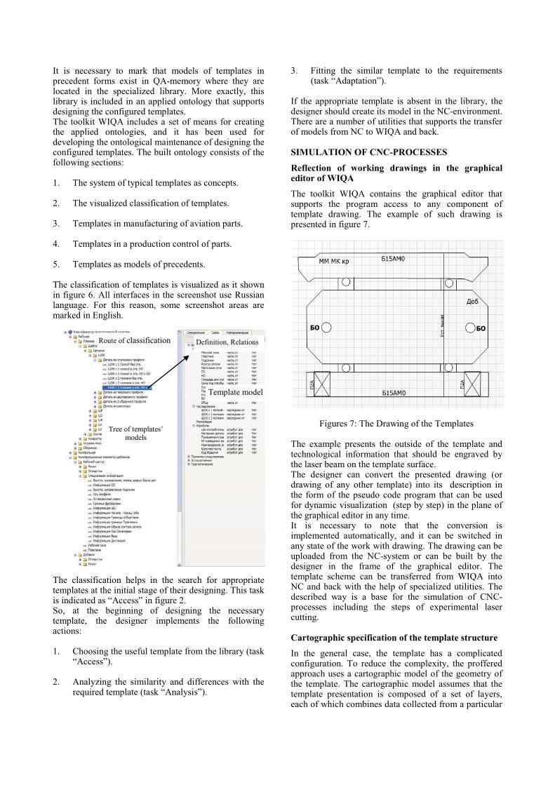
The toolkit WIQA contains the graphical editor that supports the program access to any component of template drawing. The example of such drawing is presented in figure 7.
Figures 7: The Drawing of the Templates
The example presents the outside of the template and technological information that should be engraved by the laser beam on the template surface.The designer can convert the presented drawing (or drawing of any other template) into its description in the form of the pseudo code program that can be used for dynamic visualization (step by step) in the plane of the graphical editor in any time.It is necessary to note that the conversion is implemented automatically, and it can be switched in any state of the work with drawing. The drawing can be uploaded from the NC-system or can be built by the designer in the frame of the graphical editor. The template scheme can be transferred from WIQA into NC and back with the help of specialized utilities. The described way is a base for the simulation of CNC-processes including the steps of experimental laser cutting.
Cartographic specification of the template structure
In the general case, the template has a complicated configuration. To reduce the complexity, the proffered approach uses a cartographic model of the geometry of the template. The cartographic model assumes that the template presentation is composed of a set of layers, each of which combines data collected from a particular
Tree of templates’ models
Template model
Definition, RelationsRoute of classification
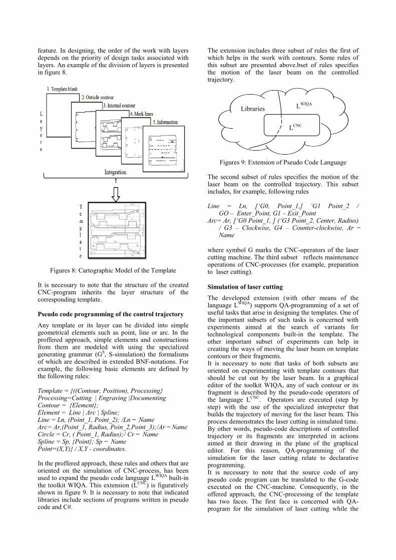
feature. In designing, the order of the work with layers depends on the priority of design tasks associated with layers. An example of the division of layers is presentedin figure 8.
Figures 8: Cartographic Model of the Template
It is necessary to note that the structure of the created CNC-program inherits the layer structure of the corresponding template.
Pseudo code programming of the control trajectory
Any template or its layer can be divided into simple geometrical elements such as point, line or arc. In the proffered approach, simple elements and constructions from them are modeled with using the specialized generating grammar (GS, S-simulation) the formalisms of which are described in extended BNF-notations. For example, the following basic elements are defined by the following rules:
Template = {((Contour, Position), Processing}Processing=Cutting | Engraving |DocumentingContour = {Element};Element = Line | Arc | Spline;Line = Ln, (Point_1, Point_2); /�����������Arc= Ar,(Point_1, Radius, Poin_2,Point_3);/Ar ���NameCircle = Cr, ( Point_1, Radius);/ ����������Spline = Sp, {Point}; � ���������Point=(X,Y)} / X,Y - coordinates.
In the proffered approach, these rules and others that are oriented on the simulation of CNC-process, has been used to expand the pseudo code language LWIQA built-in the toolkit WIQA. This extension (LCNC) is figuratively shown in figure 9. It is necessary to note that indicated libraries include sections of programs written in pseudo code and C#.
The extension includes three subset of rules the first of which helps in the work with contours. Some rules of this subset are presented above.bset of rules specifies the motion of the laser beam on the controlled trajectory.
1
2
3
Figures 9: Extension of Pseudo Code Language
The second subset of rules specifies the motion of the laser beam on the controlled trajectory. This subset includes, for example, following rules
Line = Ln, [‘G0, Point_1,] ‘G1 Point_2 / GO – Enter_Point, G1 – Exit_Point
Arc= Ar, [‘G0 Point_1, ] (‘G3 Point_2, Center, Radius)/ G3 – Clockwise, G4 – Counter-clockwise, ��� �����Name
where symbol G marks the CNC-operators of the laser cutting machine. The third subset reflects maintenance operations of CNC-processes (for example, preparation to laser cutting).
Simulation of laser cutting
The developed extension (with other means of the language LWIQA) supports QA-programming of a set of useful tasks that arise in designing the templates. One ofthe important subsets of such tasks is concerned with experiments aimed at the search of variants for technological components built-in the template. The other important subset of experiments can help in creating the ways of moving the laser beam on template contours or their fragments. It is necessary to note that tasks of both subsets are oriented on experimenting with template contours that should be cut out by the laser beam. In a graphicaleditor of the toolkit WIQA, any of such contour or its fragment is described by the pseudo-code operators of the language LCNC. Operators are executed (step by step) with the use of the specialized interpreter that builds the trajectory of moving for the laser beam. This process demonstrates the laser cutting in simulated time.By other words, pseudo-code descriptions of controlled trajectory or its fragments are interpreted in actions aimed at their drawing in the plane of the graphical editor. For this reason, QA-programming of the simulation for the laser cutting relate to declarative programming.It is necessary to note that the source code of any pseudo code program can be translated to the G-code executed on the CNC-machine. Consequently, in the offered approach, the CNC-processing of the template has two faces. The first face is concerned with QA-program for the simulation of laser cutting while the
1
2
3
LWIQA
LCNC
Libraries

second face directs on G-program controlled the laser cutting in real time. This possibility is presented in figure 10.
Figures 10: Two Faces of Pseudo Code Programs
The rational choice of the laser beam way
It should be noted the created trajectory must consist of a set of lines processed by the laser beam and a set of lines that correspond to the beam's idling. Hence, there exists the task to build the way for idling. In our study, the choice of rational way of idling is based on solving the Traveling Salesman Problem (TSP).The used solution will be explained with the scheme of the abstract template (with simple contours and without technological engraving) that combines contours presented in figure 11.
Figures 11: Development of Idling
The template includes outside contour A and contours B, D, E and F that should be cut by the laser beam. Let us suggest that the point S1 on the steel sheet S is the initial point of the controlled trajectory.
The rational choice corresponds to the following algorithmic reasoning:
1. At the first stage, a list L of “soldering points” for TSP(L) will be formed as points of tie-in contours:
1.1. The initial point of the trajectory is included in the list L as the initial point IP of TSP(L).
1.2. The next element of the list L is the point X of crossing the line, going between IP and the center of the nearest contour Yi. The point X lies on the intermedia route R the length Ln of which satisfies the condition:
X � Min (Ln1(R1), Ln2(R2),where R1 = TSP(IP, X1, C2, …Ck, … CK),
R2 = TSP(IP, X2, C2, …Ck, … CK).
1.3. Than IP =X, the variable list = (IP,C2, …Ck … CK )and GOTO step 1.2.
2. Compute idling I as I= IK+ R*, where IK �� � last piece of idling and R* = TSP’(L). Route R* doesn’t include the back way to IP.
3. Unite contours {Yi} with idling I in the geometrical description of the controlled trajectory.
In figure 11, for example, points B1 and B2 are alternative for the first choice of the point X. Idling I includes points S1, B1, D2, E1, F1 and A1.The presented reasoning reflects the idea of the rational choice. Algorithmic scheme of reasoning is only similar to the working algorithm that additionally supports the experimenting with the routes of idling.
Documenting of the CNC-process
There are two versions of documenting the CNC-process in designing of templates that are additional each other. The first version uses registering of the technological information on the face side of the manufactured template. This method is implemented byusing the laser beam, and it requires locating the units of such information on the plane of the template. An example of such locating is shown in figure 12.
Figures 12: Documenting on the Templates
Engraved instructions
Pseudo code in Russian

The second version uses traditional normative documenting in a table form (in our case with the content in Russian language). The example of such document is presented in figure 13 in order to show the constructs that can be created in WIQA-environment.
Figures 13: Normative Document of the CNC-process
Similar documents are prepared electronically, but they are also applied as hard copies. The task of documenting can be solved in NC and WIQA environment that can supplement each other. The toolkit WIQA supports real-time work with documents the content of which reflects on the semantic memory.
CONCLUSION
The described approach and its means support the pseudo-code simulation of CNC-processes in designing the configured templates of airplane parts. The use of such means opens the possibilities for experimental estimations of CNC-processes in questionable points of their life cycle. The set of such points is concerned, for example, with untypical characteristics of the controlledtrajectory. A number of such points are concerned with the use of templates for different technological applications.The specificity of the described approach is defined by following features: the use of reflections of CNC-process on the semantic memory that opens the possibility of pseudo code programming actions of the designer and moving the laser beam on the controlled trajectory; the use of models of precedents for registering the results of designing for the future reuse; the use of the ontological maintenance of real-time actions in designing.Offered versions of conceptual experiments are implemented in visual forms with using the specialized graphical editor that supports the conversions of the template geometry to the pseudo code program of its simulation in experimental aims. All achieved positive effects facilitate increasing the quality in designing of the CNC-programs.
REFERENCESAl-Kindi, G. and H. Zughaer. 2012. “An approach to
improved CNC machining using vision-based system.”Mater. Manuf. Process, 27, No.7, 765-774.
Gao, D., Z.J. Yuan, Y.X. Yao, C.Q. Liu and J.G. Li. 2008. “Cutting parameters optimization by using Particle Swarm Optimization (PSO).” Appl. Mech. Mater., 10, 879-883.
Kanan, H.R. and K. Faez. 2008. “An improved feature selection method based on Ant Colony Optimization (ACO) evaluated on face recognition system.” Appl. Math. Comput., 205, No.2, 716-725.
Kovacic M., Brezocnik M., Pahole I., Balic J., Kecelj B. 2005.“Evolutionary programming of CNC machines. Journal of Materials Processing Technology.” ��������.
Hongmei, L, L. Lei and Zh. Huiqiang. 2013. “Java language for numerical control simulation system research.”International Journal of Machine Learning and Computing, 3, No.6, �����.
Yeung, M. K. 2003. “Intelligent process-planning system or optimal cnc programming - a step towards completeautomation of CNC programming.” Integrated Manufacturing Systems, 14, No.7, ������
Yih-Fong T. 2006. “Parameter design optimisation of computerised numerical control turning tool steels for high dimensional precision and accuracy.” Materials and Design, 27, No.8, �� ��.
Raja, S. and N. Baskar. 2012. “Application of particle swarm optimization technique for achieving desired milledsurface roughness in minimum machining time.” Expert Syst. Appl., 39, No.5, 5982-5989.
Riedinger, P. and I.��. Morarescu. 2014. “A numerical framework for optimal control of switched input affine nonlinear systems subject to path constraint.” Mathematics and Computer in Simulation, Elsevier, 95, �����
Sosnin P. 2013. “Scientifically Experimental Way-of-Working in Conceptual Designing of Software Intensive Systems.” In Proc. of the. Intelligent Software Methodologies, Tools and Techniques (SoMeT), 43-51.
Ülker, E., M. E. Turanalp and H. S. Halkaci. 2009. “An artificial immune system approach to CNC tool path generation.” J. Intell. Manuf., 20. No.1, 67-77.
Wang, S.G., Y.J. Wang, G.X. Wu and Y.L. Fu. 2012. “Application of intelligence fusion algorithm in path optimization problem.” Appl. Mech. Mater., 151, 632-636.
Zuperl, U. and F. Cus. 2003. “Optimization of cutting conditions during cutting by using neural networks.”Robot. Cim-Int. Manuf., 19, No.1-2, 189-199.
Zhang, Y., X. Xu and Y. Liu. 2011. “Numerical control machining simulation: A comprehensive survey.” Int. J. Comp. Integ. M., 24, No.7, 593-609.
PETR SOSNIN was born in Ulyanovsk in the USSR, on July 12, 1945. He graduated from the Ulyanovsk Polytechnic Institute (1968).His employment experience
included the Ulyanovsk Polytechnic Institute and Ulyanovsk State
Technical University. His special field of interests includes AI applications for computer aided design. P. Sosnin defended doctor degree in Moscow Aviation Institute (1994). He is the author of ten books and more than three hundred articles.


![Non-Precedent Decision of the Administrative … › sites › default › files › err › D2...for the similar occupation of Computer and Information Systems Manager[ s ]:· directly](https://img.pdfslide.us/doc/110x75/5f0f84117e708231d4448c7f/non-precedent-decision-of-the-administrative-a-sites-a-default-a-files-a.jpg)