Embed Size (px)
Citation preview
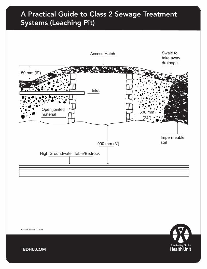
A Practical guide to class 2 sewage system
(leaching pit)
900 mm (3’)
High Groundwater Table/Bedrock
Impermeable soil
Access Hatch Swale to take away drainage
500 mm(24”)
Inlet
Open jointed material
150 mm (6”)
A Practical Guide to Class 2 Sewage Treatment Systems (Leaching Pit)
TBDHU.COM
Revised: March 17, 2016
Leaching Pits
Class 2 Sewage Treatment and Dispersal Systems
Leaching pits are used to treat and disperse grey water sewage only. They are not to be used to dispose of toilet water. Grey water sewage comes from plumbing fixtures like sinks, showers or laundry machines.
Because they treat and disperse sewage, they must be inspected an approved under the Ontario Building Code by the Thunder Bay District Health Unit.
This method of waste water treatment and dispersal is only recommended if there is no pressurized water supply and the daily volume of grey water is small.
Under the Ontario Building Code, a leaching pit can only be used if the daily flow of grey water is less than 1000 litres per day.
Location
Minimum distances must be followed
- 15m (50 feet) from any lake, pond, river, stream or any other water course
- 15m (50 feet) from any dug well, sand point well, spring or other source of potable water
These distances are minimums and may have to be increased if the soil conditions are not ideal.
The area should be elevated and well drained. Low laying areas are subject to excessive run off which will overload the pit and saturate the soils. This could result in poor treatment and increases the possibility of ground water contamination.
SoilsThe excavation for a pit must not exceed 1.25m (4 feet) in depth. Better treatment, drainage and evaporation are achieved in the soil that is just below the surface.
The bottom of the pit must be a minimum of 0.9m (3 feet) above the high water table or bedrock. Because the grey water sewage is treated by the bacteria in the soil, it is important to have 0.9m of unsaturated soil to provide adequate treatment and to protect against contamination.
The top 2-5 cm of soil will filter all solids in the grey water sewage. The remaining sewage bacteria will be treated by the soil bacteria as the liquid moves down through the soil.
Clay Soils
When installing a leaching pit in clay soils the excavation must have .60m (2 feet) of clean sand between the crushed rock and the clay soil. The sand will filter the suspended solids and treat the grey water to provide a higher quality effluent that will be more easily absorbed by the clay solid. Prior to placing the sand in the excavation the walls and bottom of the pit must be raked to remove smeared clay soils and allow more contact area with the sand, this will greatly improve the drainage abilities of the clay soil.
Leaching Pit Rock
The rock used in the leaching pit must be clean and free of fine material to prevent premature clogging of the natural soils. Caution must be taken when selecting the rock, it must be larger in size than the holes for this purpose. The rock must completely surround the barrel, excluding the top side where there are no holes. The purpose of the rock is to keep the barrel or bucket out of the saturated soils and prevent the sand from plugging the holes.
Backfilling
When the leaching pit is completed and ready to be covered, it is recommended that the fill be crowned slightly to shed rain water and snow melt. A thin layer of topsoil and sodding will prevent erosion, assist with evaporation, and divert surface water away from the leaching pit. It is mandatory that the final grade be grassed.
Leaching Pit Maintenance
Since leaching pits do not have a settlement tank it may be necessary to install a grease interceptor or a screen.
The grease interceptor is recommended if there will be kitchen wastes going into the leaching pit. The interceptor will allow for cooling of the waste water and separation of the greases and oils. It is advised to have a convenient access to the grease interceptor so it may be cleaned as required, the grease can be disposed of in your household garbage.
The installation of a screen before the leaching pit will significantly reduce the amount of solids that enter the leaching pit. (Note: if a grease interceptor is installed, a screen is not required). Access to the screen should be relatively easy but secure to prevent rodents and flies from entering. The contents in the screen should be removed regularly and disposed of in your composter or household garbage.
A leaching pit or a grease interceptor can be pumped out the same as a septic tank. If solid materials build up in the leaching pit container it is a good idea to have them removed, this will prolong the working life of the leaching pit.
Ontario Building Code
Minimum Legal Requirements for Class 2 Sewage Treatment Systems (Leaching Pit)
Section 8.4. Class 2 Sewage Systems
8.4.1. General Requirements
8.4.1.1. Scope
(1) This Section applies to the construction of a Class 2 sewage system.
8.4.1.2. Application
(1) A Class 2 sewage system shall be designed only for the treatment and disposal of greywater.
(2) The total daily design flow for a Class 2 sewage system shall be calculated based on the fixtures discharging to the system as follows:
(a) 200 L per fixture unit where there is a supply of pressurized water, and
(b) 125 L per fixture unit where there is no supply of pressurized water.
8.4.2. Design and Construction Requirements
8.4.2.1. Construction Requirements
(1) The bottom of the pit shall be at least 900 mm above the high ground water table.
(2) The pit shall be constructed in such a manner as to prevent the collapse of its sidewalls.
(3) Any material used to support or form the sidewalls of the pit shall be an open jointed ma-terial of a type that will permit leaching from the pit.
(4) The pit shall be provided with a tight, strong cover that shall remain over the pit except when it is necessary to remove it for purposes of adding greywater to or removing grey-water from the pit or for purposes of maintenance of the pit.
(5) The earth around the perimeter of the pit shall be raised or mounded to a height of at least 150 mm above ground level.
(6) The surface of the ground in the area of the pit shall be so graded that surface drainage in the area will be diverted away from the pit.
(7) The pit shall be surrounded on all sides and on its bottom by at least 600 mm of soil having a percolation time of less than 50 minutes.
8.4.2.2. Maximum Sewage Flow
(1) A Class 2 sewage system shall not be constructed where the daily design greywater flow to the system exceeds 1 000 L/day.
8.4.2.3. Sizing
(1) A Class 2 sewage system shall be designed and constructed so that the loading rate to the side walls shall be not more than the value calculated using the formula,
Where, LR = loading rate of the sidewalls in litres per day/m2, and T = percolation time.
LR = 400 T
Minimum distance from a drilled well 10m (30 feet)Minimum distance from a dug well 15m (50 feet)Minimum distance from a lake, river, etc. 15m (50 feet)Minimum distance from a property line 3m (10 feet)
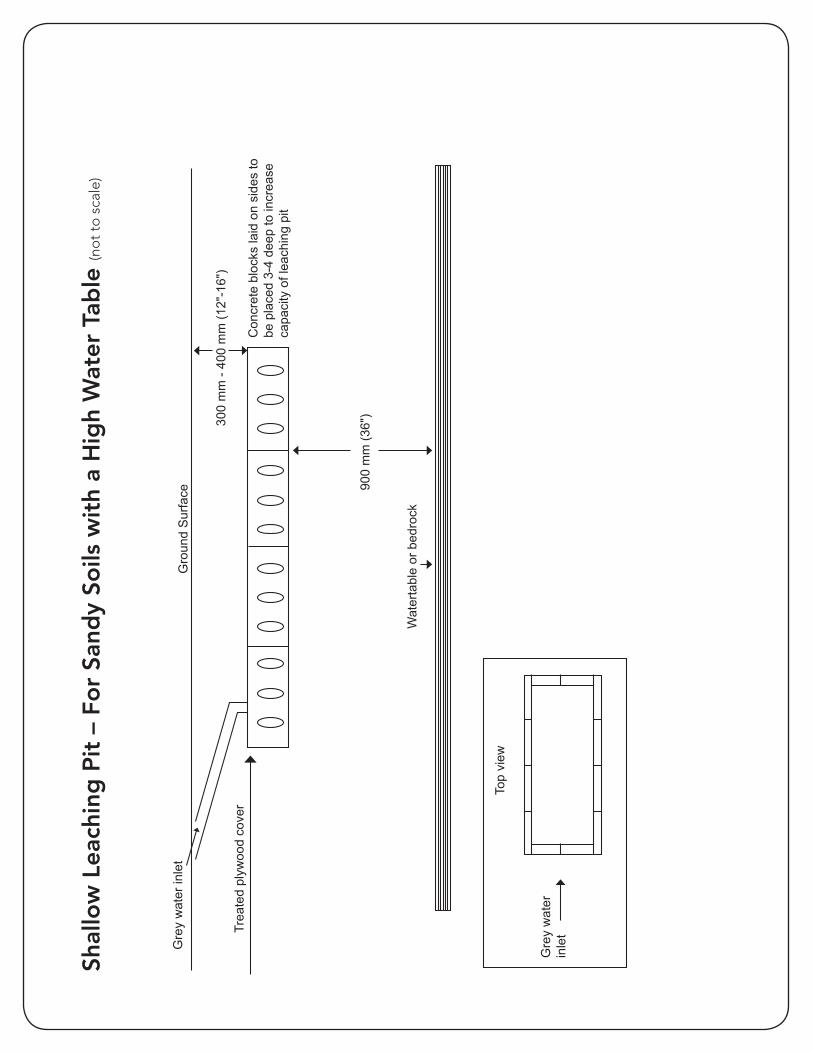
Shal
low
Lea
chin
g P
it –
Fo
r Sa
ndy
Soils
wit
h a
Hig
h W
ater
Tab
le (n
ot
to s
cale
)
Shal
low
Lea
chin
g Pi
tFo
r San
dy S
oils
With
a H
igh
Wat
er T
able
/Bed
rock
Gro
und
Sur
face
Gre
y w
ater
inle
t
300
mm
- 40
0 m
m (1
2"-1
6")
Con
cret
e bl
ocks
laid
on
side
s to
be
pla
ced
3-4
deep
to in
crea
se
capa
city
of l
each
ing
pit
900
mm
(36"
)
Wat
erta
ble
or b
edro
ck
Not
to s
cale
Top
view
Gre
y w
ater
inle
tTrea
ted
plyw
ood
cove
r
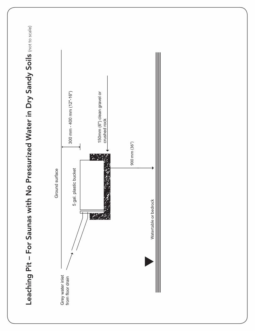
Leac
hing
Pit
for S
auna
s w
ith N
o Pr
essu
rized
W
ater
in D
ry S
andy
Soi
ls
Gro
und
surfa
ceG
rey
wat
er in
let
from
floo
r dra
in5
gal.
plas
tic b
ucke
t30
0 m
m -
400
mm
(12"
-16"
)
150m
m (6
") c
lean
gra
vel o
r
crus
hed
rock
900
mm
(36”
)
Wat
erta
ble
or b
edro
ck
* N
ot to
sca
le
Leac
hing
Pit
– F
or
Saun
as w
ith
No
Pre
ssur
ized
Wat
er in
Dry
San
dy
Soils
(no
t to
sca
le)
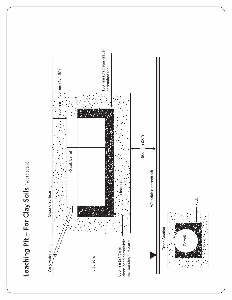
Leac
hing
Pit
for C
lay
Soils
Gro
und
surfa
ceG
rey
wat
er in
let
150
mm
(6”)
cle
an g
rave
l or
cru
shed
rock
900
mm
(36”
)
Wat
erta
ble
or b
edro
ck
* N
ot to
sca
le
Cro
ss S
ectio
n
600
mm
(24”
) min
.cl
ean
sand
com
plet
ely
surr
ound
ing
the
barr
el
clay
soi
ls
45 g
al. b
arre
l
300
mm
- 40
0 m
m (1
2”-1
6”)
clea
n sa
nd
Bar
rell
Sand
Rock
Leac
hing
Pit
– F
or
Cla
y So
ils (n
ot
to s
cale
)
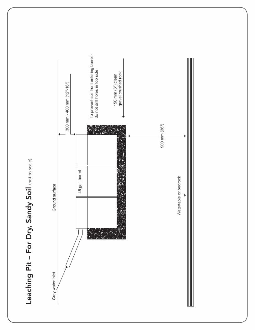
Gro
und
surfa
ceG
rey
wat
er in
let
150
mm
(6")
cle
an
grav
el c
rush
ed ro
ck
900
mm
(36"
)
Wat
erta
ble
or b
edro
ck
To p
reve
nt s
oil f
rom
ent
erin
g ba
rrel
- do
not
dril
l hol
es in
top
side
*Not
to s
cale
45 g
al. b
arre
l
300
mm
- 40
0 m
m (1
2"-1
6")
Leac
hing
Pit
– F
or
Dry
, San
dy
Soil
(no
t to
sca
le)
Leac
hing
Pit
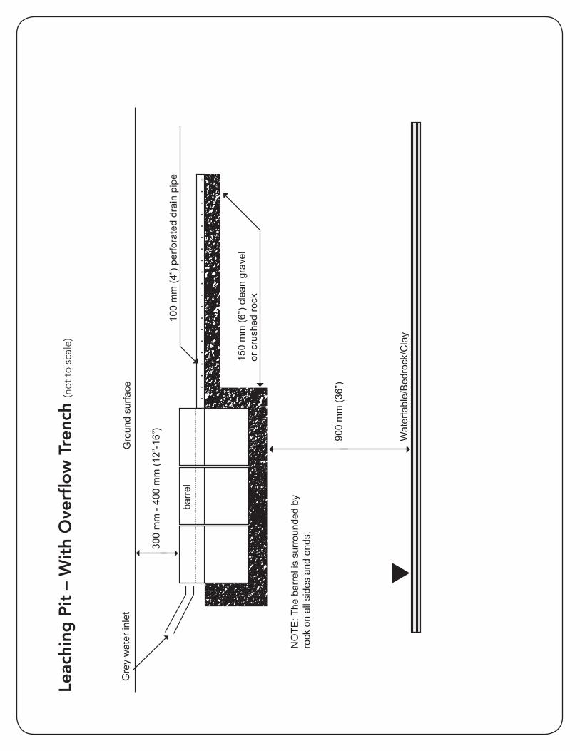
with
Ove
rflo
w T
renc
h
Gro
und
surfa
ceG
rey
wat
er in
let
100
mm
(4”)
per
fora
ted
drai
n pi
pe
150
mm
(6”)
cle
an g
rave
l or
cru
shed
rock
300
mm
- 40
0 m
m (1
2”-1
6”)
900
mm
(36”
)
Wat
erta
ble/
Bed
rock
/Cla
y
*Not
to s
cale
NO
TE: T
he b
arre
l is
surr
ound
ed b
y ro
ck o
n al
l sid
es a
nd e
nds.
barr
el
Leac
hing
Pit
– W
ith
Ove
rflo
w T
renc
h (n
ot
to s
cale
)
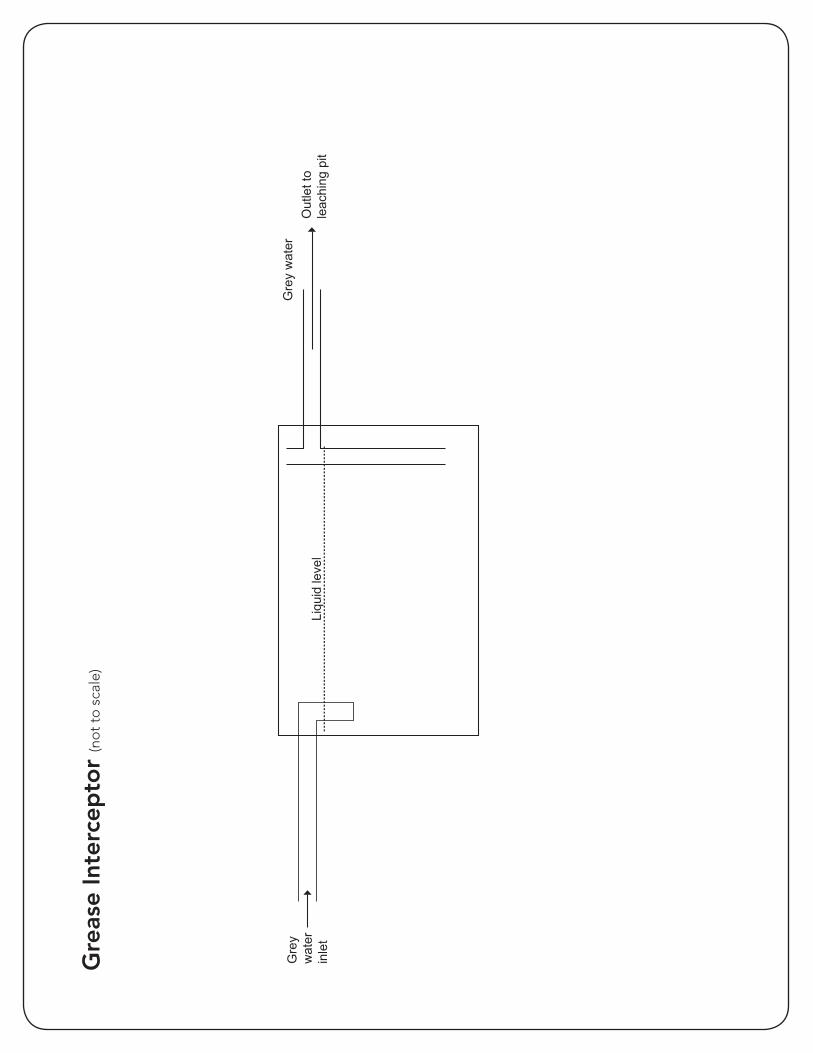
Gre
ase
Inte
rcep
tor
Gre
y w
ater
in
let
Liqu
id le
vel
Gre
y w
ater
Out
let t
o le
achi
ng p
it
*Not
to s
cale
Gre
ase
Inte
rcep
tor
(no
t to
sca
le)