Embed Size (px)
Citation preview
N Mukherjee, X Bai, D Strickland
A Practical Investigation of Power Quality using an LCL Filter Based Grid Connected Energy Storage System without Active Filtering
Energy Storage
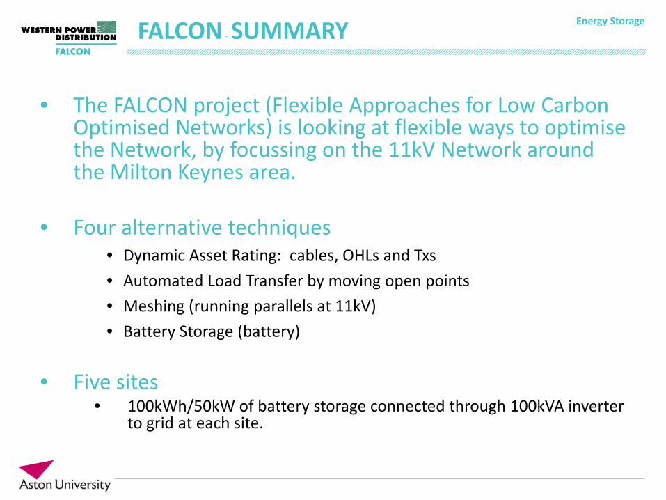
• The FALCON project (Flexible Approaches for Low Carbon Optimised Networks) is looking at flexible ways to optimise the Network, by focussing on the 11kV Network around the Milton Keynes area.
• Four alternative techniques • Dynamic Asset Rating: cables, OHLs and Txs • Automated Load Transfer by moving open points • Meshing (running parallels at 11kV) • Battery Storage (battery)
• Five sites
• 100kWh/50kW of battery storage connected through 100kVA inverter to grid at each site.
FALCON - SUMMARY
Energy Storage FALCON – ENERGY STORAGE SITES
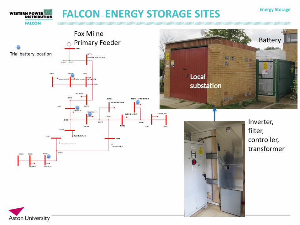
Trial battery location
Fox Milne Primary Feeder Battery
Inverter, filter, controller, transformer
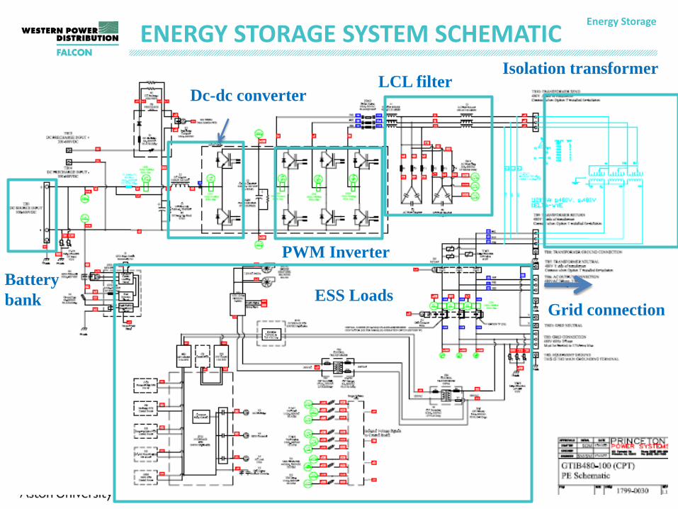
Energy Storage ENERGY STORAGE SYSTEM SCHEMATIC
PWM Inverter
Dc-dc converter LCL filter
Battery bank
Isolation transformer
ESS Loads Grid connection
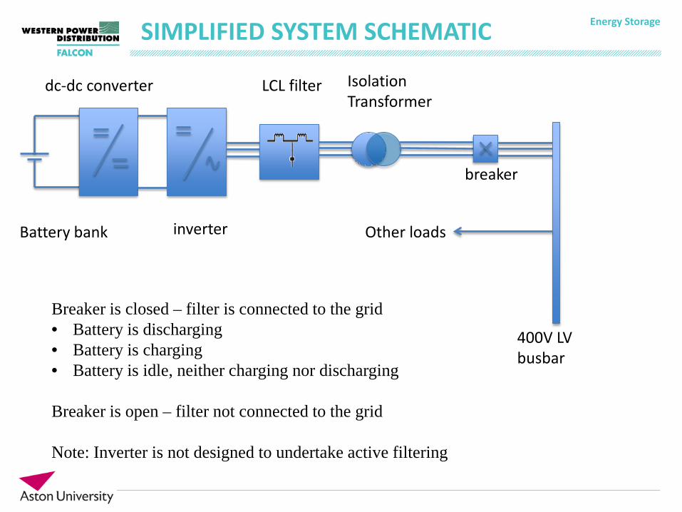
Energy Storage SIMPLIFIED SYSTEM SCHEMATIC
Breaker is closed – filter is connected to the grid • Battery is discharging • Battery is charging • Battery is idle, neither charging nor discharging Breaker is open – filter not connected to the grid Note: Inverter is not designed to undertake active filtering
Battery bank
dc-dc converter
inverter
LCL filter Isolation Transformer
400V LV busbar
Other loads
breaker
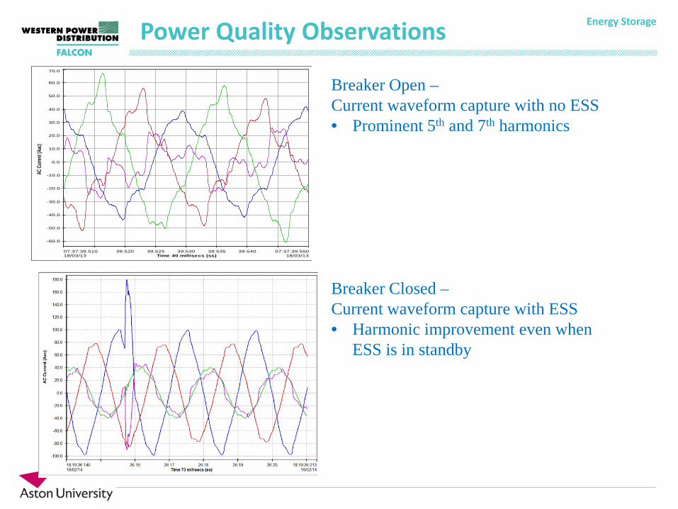
Energy Storage Power Quality Observations
07:37:39.51018/03/13
07:37:39.55018/03/13
39.520 39.525 39.530 39.535 39.540Time 40 millisecs (ss)
-60.0
-50.0
-40.0
-30.0
-20.0
-10.0
0.0
10.0
20.0
30.0
40.0
50.0
60.0
70.0
AC Cu
rrent
(Aac
)
Breaker Open – Current waveform capture with no ESS • Prominent 5th and 7th harmonics
Breaker Closed – Current waveform capture with ESS • Harmonic improvement even when
ESS is in standby
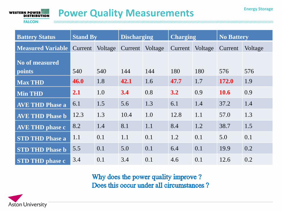
Energy Storage Power Quality Measurements
Battery Status Stand By Discharging Charging No Battery
Measured Variable Current Voltage Current Voltage Current Voltage Current Voltage
No of measured points 540 540 144 144 180 180 576 576
Max THD 46.0 1.8 42.1 1.6 47.7 1.7 172.0 1.9
Min THD 2.1 1.0 3.4 0.8 3.2 0.9 10.6 0.9
AVE THD Phase a 6.1 1.5 5.6 1.3 6.1 1.4 37.2 1.4
AVE THD Phase b 12.3 1.3 10.4 1.0 12.8 1.1 57.0 1.3
AVE THD phase c 8.2 1.4 8.1 1.1 8.4 1.2 38.7 1.5
STD THD Phase a 1.1 0.1 1.1 0.1 1.2 0.1 5.0 0.1
STD THD Phase b 5.5 0.1 5.0 0.1 6.4 0.1 19.9 0.2
STD THD phase c 3.4 0.1 3.4 0.1 4.6 0.1 12.6 0.2
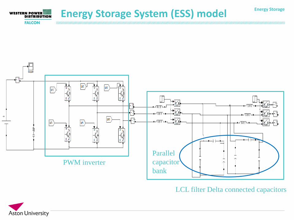
Energy Storage Energy Storage System (ESS) model
PWM inverter
LCL filter Delta connected capacitors
Parallel capacitor bank
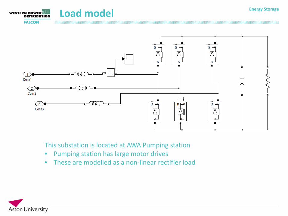
Energy Storage Load model
This substation is located at AWA Pumping station • Pumping station has large motor drives • These are modelled as a non-linear rectifier load
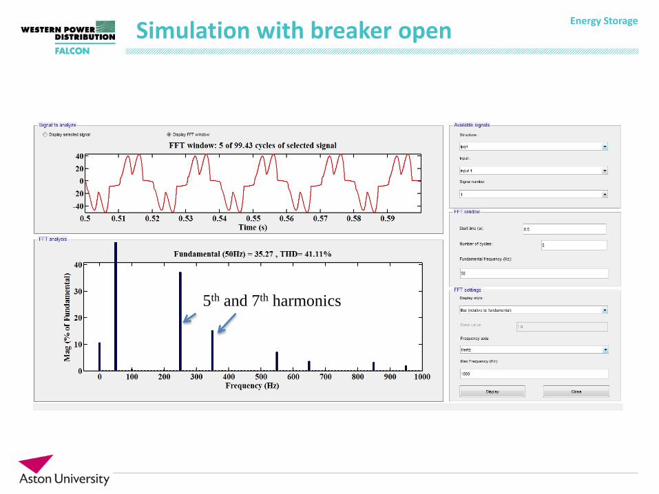
Energy Storage Simulation with breaker open
5th and 7th harmonics
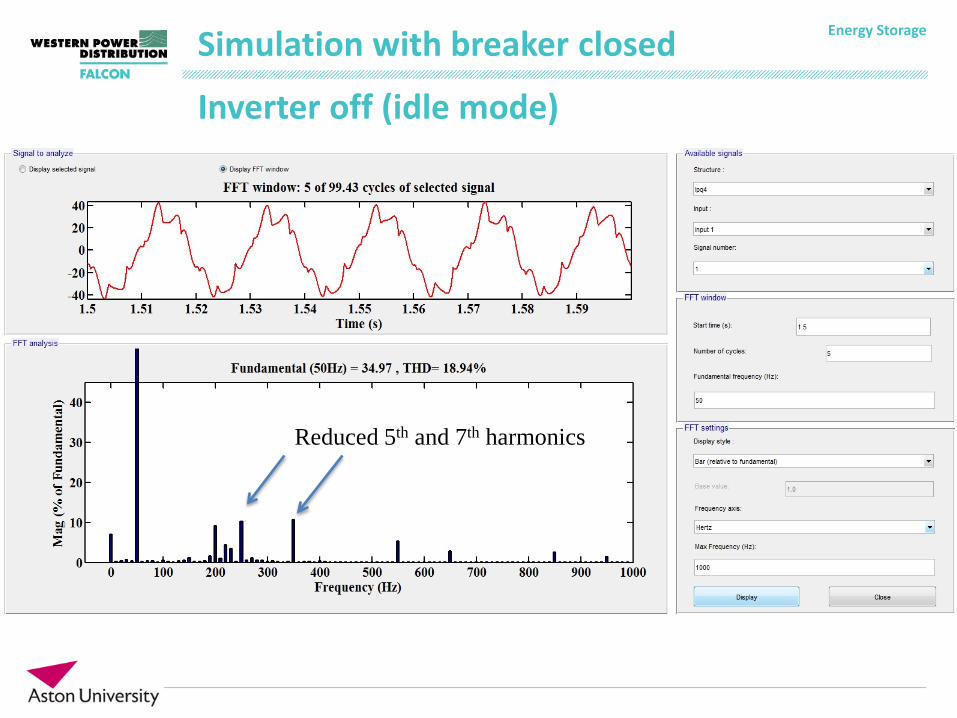
Energy Storage Simulation with breaker closed
Reduced 5th and 7th harmonics
Inverter off (idle mode)
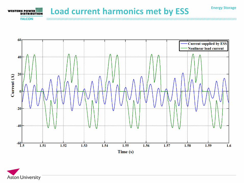
Energy Storage Load current harmonics met by ESS
Energy Storage Analysis
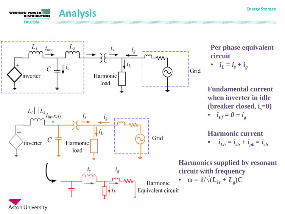
Per phase equivalent circuit • iL = is + ig
Fundamental current when inverter in idle (breaker closed, is=0) • iLf = 0 + ig
Harmonics supplied by resonant circuit with frequency • ω = 1/√(LTr + Lg)C
Harmonic current • iLh = ish + igh = ish
Energy Storage Analysis values
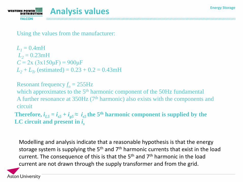
Using the values from the manufacturer: L1 = 0.4mH L2 = 0.23mH C = 2x (3x150μF) = 900μF L2 + LTr (estimated) = 0.23 + 0.2 = 0.43mH Resonant frequency fo = 255Hz which approximates to the 5th harmonic component of the 50Hz fundamental A further resonance at 350Hz (7th harmonic) also exists with the components and circuit
Therefore, iL5 = is5 + ig5 ≈ is5 the 5th harmonic component is supplied by the LC circuit and present in is
Modelling and analysis indicate that a reasonable hypothesis is that the energy storage system is supplying the 5th and 7th harmonic currents that exist in the load current. The consequence of this is that the 5th and 7th harmonic in the load current are not drawn through the supply transformer and from the grid.
Energy Storage
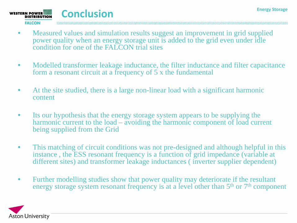
• Measured values and simulation results suggest an improvement in grid supplied power quality when an energy storage unit is added to the grid even under idle condition for one of the FALCON trial sites
• Modelled transformer leakage inductance, the filter inductance and filter capacitance
form a resonant circuit at a frequency of 5 x the fundamental
• At the site studied, there is a large non-linear load with a significant harmonic content
• Its our hypothesis that the energy storage system appears to be supplying the harmonic current to the load – avoiding the harmonic component of load current being supplied from the Grid
• This matching of circuit conditions was not pre-designed and although helpful in this instance , the ESS resonant frequency is a function of grid impedance (variable at different sites) and transformer leakage inductances ( inverter supplier dependent)
• Further modelling studies show that power quality may deteriorate if the resultant energy storage system resonant frequency is at a level other than 5th or 7th component
Conclusion