Embed Size (px)
Citation preview

Issue 03/2017
g
Technical Data
A Power Quality Interface
for Low and Medium Voltage
Smart Grids
Model PQI-DA smart
1 Wall-mounted housing
1 DIN-Rail housing
1 Panel mounting housing
1. Application
Solving all measurement tasks in electrical grids can be a daunting task. The new Power Quality Interface and Disturbance Recorder PQI-DA smart, aimed at low and medium voltage grids, represents the A-Eberle response to such needs. This central component can be used either as Power Quality-Interface in accordance with all Power Quality standards or as a device for all physically defined/measured values in typical three-phase systems.
Beside the possibility of standard evaluations, the PQI-DA smart also has a high speed fault recorder capability with a 40.96kHz/10.24kHz recording rate and a half cycle r.m.s. registration, which allows for a detailed analysis of grid disturbances.
In particular, PQI-DA smart is suitable for monitoring, registering, evaluating and recording special reference quantities or quality agreements between the supplier of energy and the end customer.
Modern Power Quality measuring devices operate in accordance with the IEC 61000-4-30 Ed.3 standard. This standard defines measurement methods that create a reference base for the user.
Devices from different manufacturers operating according to this standard, must offer the same measurement results.
IEC 61000-4-30 standard distinguishes two classes of measuring devices:
0 Class A devices - used for measurements related to contracts in customer-supplier relationships.
0 Class S devices - used to determine statistical quality values.
The PQI-DA smart meets all demands of the IEC 61000-4-30 Ed.3 (2015) standard for an A-Class device:
Parameter IEC61000-4-30 Class
Power frequency A
Magnitude of the Supply Voltage A
Flicker A
Supply voltage dips and swells A
Voltage interruptions A
Supplv voltage unbalance A
Voltage harmonics A
Voltage interharmonics A
Mains signaling voltage A
Underdevation and overdeviation A
Measurement aggregation intervals A
Time-clock uncertainty A
Flagging A
Transient influence quantities A

Design Page 2
We take care of it.
2. Design
The PQI-DA smart has been developed for measurements perfromed within public grids as well as for recording PQ data within an industrial environment up to 690V (L-L) measurement voltage. Its key characterisitcs, making it suitable for such enronments, are:
0 No moving parts (fans, hard drives etc.)
0 CAT IV
0 Extensive storage capability (can be extended up to 32 GB by the user, permitting several years recording without connection to database)
0 Optional “IEC61000-4-7 - 2kHz to 9kHz” (B1)
0 Frequency measurement of voltage and current according IEC 61000-4-7 from 2 kHz to 9 kHz.
2.1 Characteristics of the Power-
Quality Interface PQI-DA smart
2.1.1 Technical Data
0 1.7-inch colour display
0 Keypad for basic/direct device configuration
0 1 GB internal memory
0 Input channel bandwidth 20 kHz
0 4 voltage inputs FSR : 480V L-N, Accuracy < 0.1%
0 4 current inputs 1A/5A nominal,
0 Simultaneous processing of sampled and calculated voltages and currents
0 Oscilloscopic voltage and current recorder sampling rate : 40.96kHz / 10.24kHz
0 Half cycle recorder : power frequency, r.m.s. of voltages and currents, voltage and current phasors, power recording rate : ~10ms(50Hz) / ~8.33ms (60Hz)
0 Powerful recorder triggering
0 Online streaming of voltages and currents at 40.96kHz sampling rate.
0 IEC 61000-4-30, Class A voltage quality processing
0 Recording of DIN EN 50160 power quality events
0 Spectral analysis 2 kHz…9 kHz,(35 frequency bands, BW = 200Hz) of voltages and currents according (IEC 61000-4-7)
0 Phase of voltage and current harmonics n=2..50
0 2 general purpose digital inputs (Trigger, Recording Start / Stop, General documentaion of level)
0 2 relay outputs for protection monitoring and alarm
0 Complex analysis software WinPQ smart (sold as a package)
0 As an option: Analysis of the data on an MYSQL-based database using the WinPQ software package.
0 Permanent communication with up to 500 devices.
Communication Protocols
– MODBUS RTU
– MODBUS TCP
– IEC60870-5-104 (Option P1)
– IEC61850 (Option P2)
Time synchronisation protocols (Receive / Slave)
– IEEE1344 / IRIG-B000..007
– GPS (NMEA +PPS)
– DCF77
– NTP
– PTP (IEEE1588)
Interfaces
Ethernet RJ45 (10/100 Mbit)
2 * RS232/RS485
on terminals
switchable
Dimensions
L x B x H 160 x 90 x 58 mm

Page 3
Page 3
Design
Voltage inputs
Channels U1, U2, U3, UN/E/4
Electrical safety DIN EN 61010
300V CAT IV
600V CAT III
Input reference level PE
Impedance -> PE 10 MΩ || 25pF
Nominal input voltage Un 230VAC
Full scale range (FSR) 0…480VAC L-E
Waveform AC & DC, any
Maximum crest factor @ Un 3
Bandwidth DC…20kHz
Nominal power frequency fn 50Hz / 60Hz
Frequency range of the fundamental
fn ± 15% 42.5..50..57.5Hz 51.0..60..69.0Hz
Accuracy
Fundamental, r.m.s
±0.1% Un (0°C…45°C)
±0.2% Un (-25°C…55°C) @ 10%...150%Un
Fundamental, Phase ±0.01° @ 10%...150%Un
Harmonics n = 2..50, r.m.s.
±5% of reading @ Uh ≥ 1% Un
±0.05% Un @ Uh < 1% Un
Harmonics n = 2..50, Phase
±n∙0.01° @ Uh ≥ 1% Un
Interharmonics n = 1..49, r.m.s.
±5% of reading @ Uih = ≥ 1% Un
±0.05% Un @ Uih < 1% Un
Power frequency ±10mHz @ 10%...200%Un
Flicker DIN EN 61000-4-15:2011
Class F2
Dip residual voltage ±0.2% Un @ 10%..100%Un
Dip duration ±20ms @ 10%..100%Un
Swell residual voltage ±0.2% Un @ 100%..150%Un
Swell duration ±20ms
Voltage inputs
@ 100%..150%Un
Interruption duration ±20ms @ 1%..100%Un
Voltage unbalance ±0.15% @ 1%..5% reading
Mains signaling voltage (< 3kHz)
±5% of reading @ Us = 3%..15% Un
±0.15% Un @ Us = 1%..3% Un
Current inputs
Channels I1, I2, I3, IN/4
Electrical safety DIN EN 61010
300V CAT III
Input type Differential, isolated
Impedance ≤ 4mΩ
Nominal input current In
5 AAC
Full scale range (FSR) 10AAC 100AAC
Overload capacity permanent ≤ 10s ≤ 1s
20 A 100 A 500 A
Waveform AC, any
Maximum crest factor @ In
4
Bandwidth 25Hz...20kHz
Accuracy
Fundamental, r.m.s < 0,1% FSR
5%...100%
< 0,2% FSR 5% ... 10%
Fundamental, Phase ±0,1° 5%...100%
±0,2° 5% ... 10%
Harmonics n = 2..50, r.m.s.
5% 5%...100% 10% 5% ... 10%
Harmonics n = 2..50, Phase
±n∙0,1° 5%...100%
±n∙0,2° 5% ... 10%
Interharmonics n = 1..49, r.m.s.
±5% 5%...100%
±10% 5% ... 10%
Design Page 4
We take care of it.
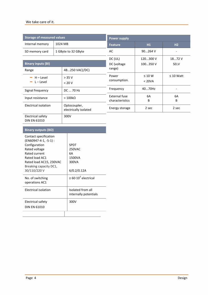
Storage of measured values
Internal memory 1024 MB
SD memory card 1 GByte to 32 GByte
Binary inputs (BI)
Range 48...250 VAC(/DC)
– H – Level – L – Level
> 35 V
< 20 V
Signal frequency DC ... 70 Hz
Input resistance > 100kΩ
Electrical isolation Optocoupler, electrically isolated
Electrical safety DIN EN 61010
300V
Power supply
Feature H1 H2
AC 90...264 V -
DC (UL)
DC (voltage range)
120...300 V
100…350 V
18...72 V
SELV
Power consumption.
≤ 10 W
< 20VA
≤ 10 Watt
Frequency 40...70Hz -
External fuse characteristics
6A B
6A B
Energy storage 2 sec 2 sec
Binary outputs (BO)
Contact specification (EN60947-4-1, -5-1) : Configuration Rated voltage Rated current Rated load AC1 Rated load AC15, 230VAC Breaking capacity DC1, 30/110/220 V
SPDT 250VAC 6A 1500VA 300VA 6/0.2/0.12A
No. of switching operations AC1
≥ 60∙103 electrical
Electrical isolation Isolated from all internally potentials
Electrical safety
DIN EN 61010
300V

Page 5
Page 5
Design
Environmental parameters Storage and transport Operation
Ambient temperature :
Limit range of operation
IEC 60721-3-1 / 1K5 -40 ... +70°C
IEC 60721-3-2 / 2K4 -40 ... +70°C
IEC 60721-3-3 / 3K6 -25 ... +55°C
Ambient temperature :
Rated range of operation H1
Rated range of operation H2
---
IEC DIN EN 61010
-25 ... +45°C
-25 ... +50°C
Relative humidity: 24h average
No condensation or ice
5...95 % 5...95 %
Solar radiations --- 700W/m2
Vibration, earth tremors IEC 60721-3-1 / 1M1 IEC 60721-3-2 / 2M1
IEC 60721-3-3 / 3M1
Electrical safety
– IEC 61010-1 – IEC 61010-2-030
Protection class 1
Pollution degree 2
Overvoltage category mains supply option : H1 H2
300V / CAT III 150V / CAT III
Measurement category 300V / CAT IV
600V / CAT III
Altitude ≤ 2000m
Electromagnetic Compatibility
Immunity
– IEC 61000-6-5, environment G
Emissions
– CISPR22 (EN 55022) , class A

Power Quality Interface for Low and Medium Voltage Networks – PQI-DA smart
2.1.2 Mechanical design
The PQI-DA smart is mountable on the wall or via its DIN rail housing.
All connections are accessible via Phoenix type terminals. The connections are made by using plug-in/clamping technology, except for the current and voltage inputs.
For the TCP/IP interface one RJ 45-connector is available.
Front view PQI-DA smart
Side view of PQI-DA smart

Page 7
Page 7
Design
2.1.3 Terminal strip number PQI-DA smart
Terminal strip no. Designation Function Terminal no.
X1 Auxiliary voltage UH L (+) 11
L (-) 12
X1 Ground GND E 13
X2 Binary input
BI1 + 21
- 22
BI2 + 23
- 24
X3
Phase voltage U1 L1 31
Phase voltage U2 L2 32
Phase voltage U3 L3 33
Neutral point voltage U4 N 34
X5
Binary output 1 R1 NC contact 51
Pol 52
NO contact 53
Binary output 2
R2 NC contact 54
Pol 55
NO contact 56
X6
Phase current L1 I1 S1 (K) S2 (l)
61 62
Phase current L2 I2 S1 (K) S2 (l)
63 64
Phase current L3 I3 S1 (K) S2 (l)
65 66
Neutral conductor / sum current I4 S1 (K) S2 (l)
67 68

Power Quality Interface for Low and Medium Voltage Networks – PQI-DA smart
2.1.4 Dimensions
2.1.5 Colour display
The device’s 1.7-inch colour display provides information about the correct connections for the measuring cables and current transducers, as well as it indicates online data on voltage, current, THD, power values and energy.
The number of PQ-events that occurred, the oscilloscope records and r.m.s. records for different periods (last day, week or month) are also displayed.

Page 9
Page 9
Design
2.2 Measurement / Functions
PQI-DA smart complies with the automatic event detection and measurement standards, which are:
EN50160 (2013) / IEC61000-2-2 / IEC61000-2-12 /IEC61000-2-4 (Class 1; 2; 3) / NRS048 / IEEE519 / IEC61000-4-30 class A / IEC6:1000-4-7 / IEC61000-4-15
Continuous Recording :
Five fixed and two variable measurement time intervals are available for continous recording:
10/12 T (200ms), 1 sec, n*sec, 150/180 T (3sec), n*min, 10 min, 2 h
Time Interval Voltage 10/ 12T
150/ 180T
10 min
2 h
1 s
N* s
N* min
Power frequency
Power frequency, 10s-Value (IEC61000-4-30)
Extremes, standard deviation of power frequency (10s)
r.m.s. values (IEC61000-4-30)
Extremes, standard deviation of T/2-values
Underdeviation [%] , Overdeviation [%] (IEC61000-4-30)
Harmonic subgroups n= 0..50 (IEC61000-4-7)
Maximum values of 10/12 T harmonic subgroups n = 2..50
Interharmonic subgroups n=0..49 (IEC61000-4-7)
Total Harmonic Distortion (THDS) (IEC61000-4-7)
Partial Weighted Harmonic Distortion (PWHD)
Unbalance, neative-/positive- sequence , sequence sign
Unbalance, zero-/positive- sequence
Positive-, negative-, zero sequence phasors
Phasors (fundamental)
Flicker (IEC61000-4-15)
Instant flicker (IEC61000-4-15)
Mains signaling voltages [%] (IEC61000-4-30)
Phase angle( zero crossings) of phase voltage harmonics n=2..50 to fundamental of reference voltage
Frequency bands 1..35 , 2kHz..9kHz, r.m.s. (IEC61000-4-7)

Power Quality Interface for Low and Medium Voltage Networks – PQI-DA smart
Time Interval Current 10/ 12T
150/180T 10 min
2 h
1 s
N* s
N* min
r.m.s. values
Extremes of T/2-values
Harmonic subgroups n= 0..50 (IEC61000-4-7)
Maximum values of 10/12 T harmonic subgroups n = 2..50
Interharmonic subgroups n=0..49 (IEC61000-4-7)
Total Harmonic Distortion (THDS) (IEC61000-4-7)
Total Harmonic Currents
Partial Weighted Harmonic Distortion (PWHD)
Partial Odd Harmonic Currents (PHC)
K-Factors
Unbalance, neative-/positive- sequence , sequence sign
Unbalance, zero-/positive- sequence
Positive-, negative-, zero sequence phasors
Phasors (fundamental)
Phase angle( zero crossings) of current harmonics n=2..50 to fundamental of reference voltage
Frequency bands 1..35 , 2kHz..9kHz, r.m.s. (IEC61000-4-7)
Time Interval Energy 10 min
2 h
1 s
N* s
N* min
Active energy, phase
Active energy, total
Exported active energy, phase
Exported active energy, total
Imported active energy, phase
Imported active energy, total
Reactive energy (inductive), phase
Reactive energy (inductive), total
Exported reactive energy (inductive), phase
Exported reactive energy (inductive), total
Imported reactive energy (inductive), phase
Imported reactive energy (inductive), total

Page 11
Page 11
Design
Time Interval Power 10 min
2 h
1 s
N* s
N* min
Active power, phase
Active power, total
Active power extremes
Reactive power, phase
Reactive power, total
Reactive power extremes
Apparent power, phase
Apparent power, total
Fundamental active power, phase
Fundamental active power, total
Fundamental reactive power, phase
Fundamental reactive power (displacement), total
Fundamental apparent power, phase
Phase angle of fundamental apparent power, phase
Fundamental apparent power, total
Phase angle of fundamental apparent power, total
Reactive distortion power, phase
Reactive distortion power, total
Active power factors, phase, total
Reactive power factors, phase, total
COS + sign, phase, total
SIN + sign, phase, total
COS + sign of reactive distortion power, phase, total
Capacitive-, inductive scaling factor of COS (-1..0..+1) :
Triggered interval mean active power, phase
Triggered interval mean active power, total
Triggered interval mean reactive power, phase
Triggered interval mean reactive power, total

Power Quality Interface for Low and Medium Voltage Networks – PQI-DA smart
2.3 Oscilloscopic recorder:
Sampling rate: 40.96kHz or 10.24kHz
Max. record length: 4s (40.96kHz) or 16s (10.24kHz)
Quantities
3-wire system 4-wire system
phase – ground voltages phase –neutral voltages
residual voltage neutral – ground voltage
phase – phase voltages
phase currents
total current neutral current

Page 13
Page 13
Design
2.4 Half cycle recorder:
Recording rate: ~10ms (50Hz) or ~8.333ms (60Hz)
Max. record length: 6min (50Hz) or 5min (60Hz)
Quantities
Power frequency
r.m.s. voltages
r.m.s. currents
Active power, phase
Reactive power, phase
Active power, total
Fundamental reactive power (displacement), total
Phase angle of fundamental apparent power, total
Voltage phasors (fundamental)
Current phasors (fundamental)
Positive-, negative-, zero sequence voltage phasors
Positive-, negative-, zero sequence current phasors

Power Quality Interface for Low and Medium Voltage Networks – PQI-DA smart
2.5 Recorder triggering:
trigger quantity lower upper step
r.m.s. phase voltages (T/2)
r.m.s. phase-phase voltages (T/2)
r.m.s. residual/neutral-ground voltage (T/2)
Positive sequence voltage (T/2)
Negative sequence voltage (T/2)
Zero sequence voltage (T/2)
Phase voltage phase (T/2)
phase voltages wave shapes (wave shape filter)
+/- threshold phase-phase voltages wave shapes (wave shape filter)
residual/neutral-ground voltage wave shape (wave shape filter)
r.m.s. phase currents (T/2)
r.m.s. total / neutral current (T/2)
Power frequency (T/2)
Binary inputs (debounced) rising, falling slope
Command external
2.6 PQ Events:
trigger quantity lower upper
voltage dip (T/2)
voltage swell (T/2)
voltage interruption (T/2)
voltage rapid voltage change (T/2) sliding average filter
mean +/- threshold
voltage change (10min)
voltage unbalance (10min)
mains signaling voltage (150/180T)
voltage harmonics (10min)
voltage THD (10min)
voltage short term flicker PST (10min)
voltage long term flicker PLT (10min)
power frequency (10s)
Page 15
Page 15
Design
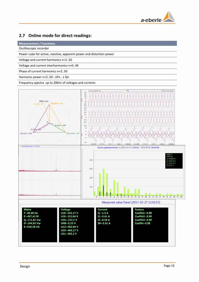
2.7 Online mode for direct readings:
Measurement / Functions
Oscilloscopic recorder
Power cube for active, reactive, apparent power and distortion power
Voltage and current harmonics n=2..50
Voltage and current interharmonics n=0..49
Phase of current harmonics n=2..50
Harmonic power n=2..50 : ±Pn , ± Qn
Frequency spectra up to 20kHz of voltages and currents

Power Quality Interface for Low and Medium Voltage Networks – PQI-DA smart
3. Order specifications PQI-DA smart
For determining the smart code ordering details:
0 Only one unit can be ordered for codes with the same capital letter.
0 When a code's capital letter is followed by the number 9, additional information in plain text is required.
0 When a code's capital letter is followed only by zeros, the code may be omitted.
Characteristic Code
Power Quality Interface for Medium and High Voltage Networks 0 4 voltage converters, 4 current transformers 0 In accordance with DIN EN-50160 and IEC 61000-4-30 (Class A) 0 2 digital inputs 0 2 relay outputs 0 WinPQ smart software for PQI-DA smart
PQI-DA smart
Current inputs 0 4 current inputs for metering circuit 1A/5A (range 10A) 0 4 current inputs for protection circuit 1A/5A (range 100A)
C30 C31
Supply voltage 0 AC 90 V..110 V..264 V or DC 120 V..220 V..350 V 0 DC 18 V...60 V...70 V
H1 H2
Option IEC61000-4-7 (40,96kHz sampling) 0 10,24kHz sampling; without 2kHz to 9kHz measurement 0 Frequency measurement of voltage and current from 2 kHz to 9 kHz
40.96kHz sampling oscilloscope recorder
B0 B1
Option communication protocol 0 Modbus RTU & TCP 0 IEC 60870-5-104 (RJ45) 0 IEC61850 (RJ45)
P0 P1 P2
Rated value of the input voltage 0 100V / 400 V / 690 V (CAT IV 300V)
Operating instructions 0 German 0 English 0 French 0 Spanish 0 Italian 0 Chinese 0 Russian
G1 G2 G3 G4 G5 G6 G7

Page 17
Page 17
Order specifications PQI-DA smart
3.1 Option PQI-DA smart
Additions to PQI-DA smart Code
SD-memory card (external): 4 GByte industrial standard 900.9099.4
DIN-rail, wall mounted housing Frame for panel mounting
564.0435
564.0433
Radio time clock interface DFC 77 111.9024
GPS clock - H1: AC/DC 88 V...264 V D2: RS485
GPS clock - H2: DC 18 V...72 V D2: RS485
111.9024.45
111.9024.46
Software WinPQ smart Code
Software WinPQ smart
For parameterising PQI-DA smart, as well as reading PQI-DA smart measurement data and online data as a single-user licence – sold as a package
WinPQ smart
WinPQ database Code
Software WinPQ
For the parameterisation, archiving and analysis of PQI-D/DA measurement data with the following basic functions: 0 32-bit/64-bit Windows program interface 0 Database for storing measurement data for each measurement point
Date access via TCP/IP network 0 Possibility of visualization for all measurement variables accessible from a PQI-
D/DA as a function of time and as a statistical magnitude 0 A second seat license is included in the price
WinPQ
Licences 0 Single-user license for 2 x PQI-D/DA/smart 0 Single-user license for 2 - 10 x PQI-D/DA/smart 0 Single-user license for > 10 x PQI-D/DA/smart
L0 L1 L2
Operating instructions 0 German 0 English 0 French
A1 A2 A3

Power Quality Interface for Low and Medium Voltage Networks – PQI-DA smart

Page 19
Page 19
Order specifications PQI-DA smart

Power Quality Interface for Low and Medium Voltage Networks – PQI-DA smart
A. Eberle GmbH & Co. KG
Frankenstraße 160 D-90461 Nuremberg
Tel.: +49 (0) 911 / 62 81 08-0 Fax: +49-(0)911-62 81 08 99 E-mail: [email protected]
http://www.a-eberle.de
Presented by:
_______________________________
Copyright 2017 by A. Eberle GmbH & Co. KG
Subject to change without prior notice.
Date: 4/25/2017