Embed Size (px)
Citation preview

Received December 13, 2018, accepted January 14, 2019, date of publication January 29, 2019, date of current version February 14, 2019.
Digital Object Identifier 10.1109/ACCESS.2019.2895675
A Power Distribution Control Strategy BetweenEnergy Storage Elements and Capacitors forCascaded Multilevel Inverter With HybridEnergy SourcesZHAO LIU , YUE ZHANG, SHANSHAN ZHAO, AND JIAN GONGSchool of Automation, Nanjing University of Science and Technology, Nanjing 210094, China
Corresponding author: Zhao Liu ([email protected])
This work was supported in part by the National Natural Science Foundation of China under Grant 51507086, and in part by theNatural Science Foundation of Jiangsu Province under Grant BK20150839.
ABSTRACT The key technology of a cascaded multilevel inverter with hybrid energy sources lies in thepower distribution among different chains. A power distribution control strategy between the energy storageelements and the capacitors is proposed to achieve fault tolerant control. In the cascaded multilevel inverterwith hybrid energy sources, the chains with energy storage elements can operate in four quadrants, whilethe chains with capacitors can only operate in two quadrants. With the proposed control method, the activepower distribution is realized by active voltage vector superposition, and the reactive power distribution isachieved by initial operation point selection. This enhances both the system reliability and availability whileenabling continuous operation in four quadrants. Meanwhile, the stable operation region and the range of theinitial operating point have been derived by the vector analysis to avoid over-modulation. An experimentalprototype based on a single-phase link with two series chains has been built in the laboratory. The simulationand experimental results are provided to demonstrate the effectiveness of the proposed control method.
INDEX TERMS DC-AC power converters, power control, voltage control, energy conversion, energyexchange, energy storage, power generation control.
I. INTRODUCTIONOver the last decade, renewable energy sources such asphotovoltaics and wind-power generation have been progres-sively installed within distribution power systems. However,the output power of photovoltaics and wind-power genera-tion depends on weather and climate conditions significantly.Electric power utilities may face system stability issues,which are related to voltage and frequency fluctuations result-ing from the intermittent nature of renewable energy sources.Energy storage helps to mitigate the stochastic nature ofrenewable resources. In addition, energy storage can quicklydeliver active power to provide services, such as spinningreserve, peak shaving, load levelling, and load frequencycontrol [1]–[3]. Compared to other energy storage system,battery energy storage system (BESS) has been proved moreattractive for its fast reaction and high power density. A BESS
The associate editor coordinating the review of this manuscript andapproving it for publication was Bora Onat.
installation has two major hardware components: a powerconversion system (PCS) and a network of battery energystorage units [4]. A comparison among a conventional designusing parallel power blocks (PBBESS), a design using intel-ligent battery packs (IBP-BESS) and a cascaded H-bridgedesign (CHB-BESS) has been given in reference [5], cas-caded multilevel inverter has the characteristics that it couldbe connected with medium-voltage grid directly withouttransformer and its capacity could be expanded easily, so itis widely used as the PCS of BESS [6], [7]. Beyond offeringabove significant benefits, the cascaded BESS suffers fromthe drawback of employing great number of components,which will lead to reduction in the reliability.
The so-called ‘‘fault tolerance’’ for cascaded multilevelinverter has been investigated in [8]–[12]. For a cascaded con-verter, fault-tolerant control can be achieved by two ways [8]:
1) by providing a redundant converter cell in each phase,and bypassing not only the faulty converter cell, but alsotwo healthy converter cells in the other two phases;
168802169-3536 2019 IEEE. Translations and content mining are permitted for academic research only.
Personal use is also permitted, but republication/redistribution requires IEEE permission.See http://www.ieee.org/publications_standards/publications/rights/index.html for more information.
VOLUME 7, 2019

Z. Liu et al.: Power Distribution Control Strategy Between Energy Storage Elements and Capacitors
2) by bypassing the faulty converter cell only, withoutproviding redundant converter cells.
The first category can ride through a fault in atleast one converter cell at the rated voltage and power.Reference [9] proposes a fault-tolerant control strategy toachieve the N+1 redundancy in a cascaded H-bridge mul-tilevel converter (CHMC) based STATCOM system andredundant H-bridge building block (HBBB) is designed andapplied to deal with the switching device failure and improvethe reliability and availability. In [10], a method for fault-tolerant operation of three phase CHB converters was pre-sented, which employs an auxiliary module made by sixsemiconductor switches and one capacitor in series to theCHB converter. This category of approaches is often usedin critical applications at the expense of cost and efficiency.The second category can tolerate a fault in a few convertercells with a reduced voltage and power. Reference [11] hasproposed a modified level-shifted pulse width modulation(LS-PWM) strategy to apply the neutral shift for fault-tolerant control of cascaded H bridge multilevel inverters(CHMIs). When the proposed LS-PWM is applied with theneutral shift, the cascaded multilevel inverter can maintaincontinuous operation, producing three-phase balanced line-to-line voltages and currents at the ac side during a switchingdevice fault. The proposed fault-tolerant strategy in [12]is based on an adaptation of the modified space vectormodulation (SVM) technique to the fundamental phase-shiftcompensation method, and it generates balanced line-to-linevoltages with increased voltage levels in the faulty condition.Although a tolerable degree of reduction in voltage andpower depends on the application, it is acceptable in terms ofavoiding the complete shutdown in most cases. The parallelconnection is required for the battery strings, each of whichconsists of series-connected battery modules. Thus, desirablepower and energy ratings can be obtained by connectingmultiple battery strings in parallel. However, parallel andseries connections of many battery modules inherently bringcomplexity to the battery management system (BMS) [3],and too many batteries and BMS are prone to failure.The battery consistency, overvoltage, overheating, and BMScommunication failure can cause the fault, either of theabove two methods will cause voltage and power loss if thebatteries/BMS fail. Actually, the fault batteries/BMS can beremoved by switching off the contactors to form cascadedmultilevel inverter with hybrid energy sources, the battery andthe capacitor serve as two main DC sources, shown in Fig.1.
The cascadedmultilevel inverter with hybrid energy sourcehave been widely studied and applied. The key lies in thepower distribution among different chains. In [13], a waybased on a time-domain modulation strategy is presented,it can achieve any dc voltage ratio between the H-bridgesof the single-dc-source cascaded H-bridge converter. In [14],using the phase-shift modulation approach, a new controlmethod for cascaded H-bridge multilevel converters fedwith only one independent dc source is presented. The pro-posed method has a wide voltage regulation range for the
FIGURE 1. Star-connected cascaded multilevel inverter with hybridenergy sources.
replacement capacitors in the H-bridge cells. A segmentedpower-distribution control system based on a hybrid cascadedmultilevel converter with parts of energy storage is proposedin [15], a novel three-segmented control strategy based onactive and reactive power control is proposed to realize theenergy flow among the ordinary cells, storage cells, andthe motor. A power-distribution strategy between the energysource, the energy storage, and the electric motor has beendeveloped and implemented in [16], an autonomous powerregenerative control has been proposed to achieve the voltagebalancing control of the energy storage. However, the abovemethods are all controlled as voltage source converter (VSC),it is not suitable for grid-connected inverter. The controlstrategy of grid-connected asymmetrical cascaded multi-level converter has been considered in [17], the battery andthe electrical double layer capacitor (EDLC) serve as dcsources, and feed forward space vector modulation technique(FFSVM) is used to distribute active power between batteryand EDLCs. With the proposed voltage feed-forward mecha-nism, the hybrid energy storage system can flexibly operate indifferent modes, but it cannot regulate the active and reactivepower continuously. Furthermore, the distribution of reactivepower among chains is not considered. Traditionally, thedecoupled active and reactive power distribution control isadopted in cascaded multilevel inverter with hybrid energysources. A CHB inverter topology with both PV arrays andenergy storage elements is proposed in [18], and a two-layerhierarchical control is also developed. The lower layer isresponsible for system PQ control and distribution amongeach HB, and the upper layer decides power dispatchingand generate power references for each H-bridge (HB).However, there is a delay in the active and reactive decoupling
VOLUME 7, 2019 16881

Z. Liu et al.: Power Distribution Control Strategy Between Energy Storage Elements and Capacitors
separation, so its dynamic response is slow and the chainsmay also be over modulated during the dynamic process.
This paper proposes a power distribution control methodfor cascaded multilevel inverter with hybrid energy sources.In particular, the active power distribution between the energystorage elements and the capacitors is realized by active volt-age vector superposition, and the reactive power distributionis achieved by initial operation point selection. Moreover,the selection range of initial operation point is describedin detail in this paper, which can avoid over-modulation.To enhance both system reliability and redundancy, the stableoperation region also has been derived by vector analysis.Accordingly, the proposed power distribution control methodwill not only make full utilization of the system’s capacity butalso enable continuous operation in four quadrants, it can beused not only in the occasion of batteries and capacitors toachieve fault-tolerant control but also in other occasions withhybrid energy source such as batteries and PV, batteries andEDLCs and so on.
This paper is outlined as follows. After the introductionsection, a simplified equivalent model is given and the oper-ation modes are described in Section II. An insightful illus-tration of the proposed power distribution strategy betweenthe energy storage and the capacitors is shown in Section III.The range of initial operation point is also derived in thissection to avoid over-modulation. Section IV presents thestable operation range of cascaded multilevel inverter withhybrid energy sources by vector analysis. In Section V andSection VI, the proposed system is firstly simulated in aMATLAB/Simulink simulation platform and then imple-mented on an experimental prototype based on a single phaselink with two series chains. Simulation and experimentalresults are presented to verify the effectiveness of the pro-posed control method. Finally, conclusions are presented inSection VII.
II. EQUIVALENT MODEL OF SYSTEMAccording to [19] and [20], either star-connected or delta-connected cascaded multilevel inverter can be divided intothree single-phase links by individual control, so taking anarbitrary link in Fig.1 as study object, which is shown in Fig.2.It can be assumed that there are M -chains with batteries andN -chains with capacitors in the link. Where vs is the gridvoltage, is is the grid current, Vcap and Vbat are respectivelythe DC voltages, Ls is the filter inductor, which ignores theresistor. A pre-charge circuit is formed by R, J1 and J2, L1 isused to reduce the second harmonic current. By the methodsproposed in [21] and [22], all chains with batteries and allchains with capacitors can respectively be assumed to thesame.
To simplify the analysis, the link can be equivalent to twoseries chains, as shown in Fig.3. Where vr1 is the outputvoltage of chains with batteries, vr2 is the output voltage ofchains with capacitors, vL is the inductor voltage.vr1, vr2 and vL are consisted of fundamental voltage and
harmonic voltage. Usually the phase-shift SPWMmodulation
FIGURE 2. The single-phase link.
FIGURE 3. The equivalent circuit of single-phase link.
is adopted in cascaded multilevel inverter and it will not beover modulated, the harmonic voltages are mainly switchingfrequency harmonic and are relatively small, so they can beignored.
Thus:
vs = vr + jωLs · is = vr1 + vr2 + jωLs · is (1)
where:
vs = Vs 6 0vr1 = Vr1 6 ϕ3vr2 = Vr2 6 ϕ4Vr1 = Ma · Vr1m = Ma ·MVbat/
√2
Vr2 = Mb · Vr2m = Mb · NVcap/√2
(2)
The grid voltage vs is chosen as the phase reference andits RMS is Vs; Vr1 and ϕ3 are respectively the RMS andphase of vr1; Vr2 and ϕ4 are respectively the RMS and phaseof vr2; Vr1m and Vr2m are respectively the maximum of Vr1andVr2;Ma andMb are respectively themodulation ratio, and0 ≤ Ma ≤ 1, 0 ≤ Mb ≤ 1.The cascaded multilevel inverter with hybrid energy
sources can operate in four quadrants, and the vector dia-grams of operation mode are shown in Fig.4. Where δ is the
16882 VOLUME 7, 2019

Z. Liu et al.: Power Distribution Control Strategy Between Energy Storage Elements and Capacitors
FIGURE 4. The vector diagrams of operation mode. (a) Quadrant three.(b) Quadrant four. (c) Quadrant two. (d) Quadrant one.
angle between vr and is, and it also denotes the power factorof the hybrid energy storage system.
The operation modes in Fig.4 can be divided into twocategories, the operation modes of Fig.4(a) and Fig.4(b) aresimilar and can be defined as inductive mode while theoperation modes of Fig.4(c) and Fig.4(d) can be defined ascapacitive mode.
III. PROPOSED CONTROL METHODIn Fig.3, the chain with batteries can operate in four quadrantswhile the chain with capacitors can only operate in two quad-rants. Ideally the chain with capacitors cannot absorb activepower, but because there is power loss in the chain, includingDC-side power loss, switching loss, and so on, it needs toabsorb a little active power to cancel out the loss. The aimof active power distribution is that the batteries provide allactive power and the capacitors absorb a little active power tomaintain its DC-side voltages.
Taking the inductive mode in Fig.4(a) for example, sincethe other modes have the similar analyzing methods andconclusions. The vector diagram is shown in the Fig.5. CC1 isa circle centered on point O1 and its radius is Vr1m. By for-mula (2), arbitrary vector in CC1 can be obtained by changingthe modulation ratio Ma and phase angle ϕ3 of vr1, so CC1represents the output voltage range of vr1 without over-modulation. Similarly, CC2 is a circle centered on point O2
FIGURE 5. The vector diagrams in inductive mode.
and its radius is Vr2m, which represents the output voltagerange of vr2 without over-modulation. The black shadow areaP is the overlapping part of CC1 and CC2, which means thatthe steady-state operating point can only be synthesized inthis area, for only in this area vector vr1 and vector vr2 cansynthesis vector vr without over-modulation.
The power loss of chain with capacitors is small and can beneglected, so vr2 must be perpendicular to is, which is shownin Fig.6. The A1A2 is the line segment where vr2 and area Pintersect, which means that the steady-state operating pointcan only be located at this line segment.
FIGURE 6. The stable operation region in inductive mode.
According to the balance control proposed in litera-ture [3], the initial operation point is located at point B, andO1B:O2B=MVbat :NVcap, which is shown in Fig.7, then avector parallel with is which can be called ‘‘the active powervoltage vector’’ is added based on the point B.
FIGURE 7. The initial operation point.
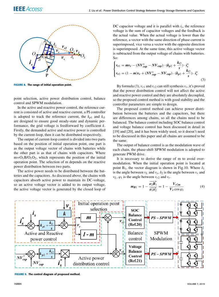
But it can be known from Fig.7 that it is difficult to findappropriate active power voltage vector which makes thepoint B transition to A1A2, so the initial operation pointcan be adjusted, shown in the Fig.8. Two lines parallel to ishave been given from points A1 and A2 respectively, and theparallel lines intersect vr at points B1 and B2 respectively. Theinitial operation point B can be selected on the line segmentB1B2, and it is easy to find appropriate active power voltagevector to make point B transition to point A.
The control block diagram is proposed in Fig.9. Theproposed control method is consisted of five parts, includ-ing active and reactive power control, initial operation
VOLUME 7, 2019 16883
Z. Liu et al.: Power Distribution Control Strategy Between Energy Storage Elements and Capacitors
FIGURE 8. The range of initial operation point.
point selection, active power distribution control, balancecontrol and SPWM modulation.
In the active and reactive power control, the reference cur-rent is consisted of active and reactive current, a PI controlleris adopted to track the reference current, the kp1 and ki1are designed to ensure good steady-state and dynamic per-formance, the grid voltage is feedforward by coefficient k .Firstly, the demanded active and reactive power is controlledby the current-loop, then it can be distributed respectively.
The output of current-loop control is divided into two partsbased on the position of initial operation point, one part isas the output voltage vector of chains with batteries whilethe other part is as that of chains with capacitors. Wherem=O1B/O1O2, which represents the position of the initialoperation point. The selection of m depends on the reactivepower distribution between two parts.
The active power needs to be distributed between the bat-teries and the capacitors. As discussed above, the chains withcapacitors absorb active power to maintain its DC-voltage,so an active voltage vector is added to its output voltage,the active voltage vector is generated by the closed loop of
DC capacitor voltage and it is parallel with is, the referencevoltage is the sum of capacitor voltages and the feedback isthe actual value. When the actual voltage is lower than thereference, a vector with the same direction of phase current issuperimposed, vice versa a vector with the opposite directionis superimposed. At the same time, this active voltage vectoris subtracted from the output voltage of chains with batteries.So:vr1 = mvr − (NV∗cap − NV cap) · (kp2 +
ki2s) · i∗s
vr2 = (1−m)vr + (NV∗cap − NV cap) · (kp2 +ki2s) · i∗s
(3)
By formula (3), vr1 and vr2 can still synthesis vr , it’s provedthat the power distribution control will not affect the activeand reactive power control and they are absolutely decoupled,so the proposed control method is with good stability and thecontroller parameters are simple to design.
The proposed control method can achieve power distri-bution between the batteries and the capacitors, but thereare differences among chains, so all the chains need to bebalanced. The balance control including SOC balance controland voltage balance control has been discussed in detail in[19] and [20], and it has been widely used, so it doesn’t needto be discussed in this paper and all chains are assumed to bethe same.
The output of balance control is as the modulation wave ofeach chain, the phase-shift SPWM modulation is adopted togenerate PWM drive.
It is necessary to derive the range of m to avoid over-modulation. When the initial operation point is located atpoint B1, the vector diagram is shown in Fig.10. Where δ1is the angle between vL and vs, δ2 is the angle between vr andvL , ϕ1 is the angle between vr2 and vr .
mB1 = 1−−−→o2B1−−→o1o2
= 1−V r2m
V r cosϕ1(4)
FIGURE 9. The control diagram of proposed method.
16884 VOLUME 7, 2019

Z. Liu et al.: Power Distribution Control Strategy Between Energy Storage Elements and Capacitors
FIGURE 10. The calculation of m when the initial operation point is atpoint B1.
where:
δ1 = δ −π
2
Vr =√V 2s + V
2L − 2 · Vs · VL · cos δ1
cosϕ1 = − cos δ2 =V 2s − V
2r − V
2L
2 · Vr · VLVr2m =
NVcap√2
(5)
Similarly, when the initial operation point is located atpoint B2, the vector diagram is shown in Fig.11. Where ϕ2 isthe angle between vr1 and vr2, ϕ3 is the angle between vr1and vs.
mB2 = 1−−−→o2B2−−→o1o2
= 1−V r2
V r cosϕ1(6)
where:
δ1 = δ −π
2
Vr =√V 2s + V
2L − 2 · Vs · VL · cos δ1
cosϕ1 = − cos δ2 =V 2s − V
2r − V
2L
2 · Vr · VLVr1m =
MVbat√2
ϕ2 = π − arcsin(VsVr1m
· sin δ1)
ϕ3 = π − ϕ2 − δ1 = arcsin(VsVr1m
· sin δ1)− δ1
Vr2 =sinϕ3sin δ1
· Vr1m − VL
(7)
The initial operation point B is located on the line segmentB1B2, so
m ∈[mB1 mB2
]The selection of m depends on the distribution of reactive
power between two chains.When the hybrid energy storage system operates in capac-
itive mode, the range of initial operation point is shownin Fig.12. Similarly, the range of m can be also derived bygeometric analysis.
FIGURE 11. The calculation of m when the initial operation point is atpoint B2.
FIGURE 12. The range of initial operation point in capacitive mode.
IV. STABLE OPERATION RANGE ANALYSISWhen the hybrid energy storage system operates in inductivemode, it can be known from Fig.6 that vr2 must intersectarea P to avoid over-modulation of the system, so it is neededto meet the following two conditions in Fig.13. Where γ isthe angle between O2O and vr .
1) The triangle O1O2A2 needs to be within the triangleO1O2O, which means ϕ1 < γ .2) The triangle O1O2O3 can be constructed, which means
cosδ1 ≤ 1.
FIGURE 13. The operation region of hybrid energy storage system ininductive mode.
VOLUME 7, 2019 16885

Z. Liu et al.: Power Distribution Control Strategy Between Energy Storage Elements and Capacitors
(a) ϕ1 < γ
Then it can be concluded that:cosϕ1 = − cos δ2 = −
V2r + V
2L − V
2s
2V rVL
cos γ =V2r + V
2r2m − V
2r1m
2V rV r2mcosϕ1 > cos γ
(8)
So,
Vr <
√VL · (V2
r1m − V2r2m)+ V r2m · (V2
s − V2L)
VL + V r2m(9)
(b) cosδ1 ≤ 1Where,
cos δ1 =V2s + V
2L − V
2r
2V sVL(10)
So,
V r ≥
√V2s + V
2L − 2V s · VL (11)
So the range of Vr can be derived by (9) and (11), then theranges of δ and δ1 also can be derived by (10) and (12).
δ = δ1 +π
2(12)
When the hybrid energy storage system operates in capac-itive mode, the operation range can be derived similarlyaccording to Fig.14.
FIGURE 14. The operation region of hybrid energy storage system incapacitive mode.
V. SIMULATIONA. THE PARAMETERS OF SIMULATION SYSTEMIn order to verify the proposed theoretical analysis, the modelof cascaded multilevel inverter with hybrid energy sourcescontrolled by the proposed strategy is simulated withMATLAB/SIMULINK. The simulation is based on a singlephase link with two series chains as shown in Fig.3, one chainis with battery as DC source and the other is with capacitor.This paper focuses on the power distribution between energystorage elements and capacitors, so two chains are enough.The detailed parameters are listed in Table 1.
TABLE 1. Main parameters of cascaded multilevel inverter with hybridenergy sources.
The simulation is still based on the inductive mode shownin Fig.5. According to the system parameters, there are:
V r1m =MVbat√2= 70.7V
V r2m =NV cap√2= 141.4V
V s = 180VVL = Is · ωLs = 10.1V
(13)
It can be concluded from formulas (9), (10) and (11), thenV r ∈[169.9469V 170.7624V
]δ1 ∈
[0 0.3944
] (14)
When δ1 = 0, the range of m can be obtained fromformulas (4) and (6), that:
m ∈[0.1678 0.6431
](15)
When δ1 = 0.3944, the range of m can be obtained from(4) and (6), that:
m = 0.0942 (16)
By formulas (15) and (16), it is proved that vr2 intersectsarea P within the range of δ1.
Let δ1 = π /12, the range of m can be obtained fromformulas (4) and (6), that:
m ∈[0.0844 0.3556
](17)
Simulation has been given respectively when m=0.2,0.4 and 0.6. The simulation is based on the proposed controlmethod in Fig.9 without consideration of balance control. Allthe active power is provided by chain with batteries, while thechain with capacitors absorbs a little active power to maintainits DC voltage, the reactive power is distributed by initialoperation point if it is not over modulated.
16886 VOLUME 7, 2019

Z. Liu et al.: Power Distribution Control Strategy Between Energy Storage Elements and Capacitors
FIGURE 15. The simulation when m=0.2, δ1 = π/12. (a) Voltages of battery and capacitor. (b) Grid voltage and current. (c) The output voltageand current of chain with battery. (d) The output voltage and current of chain with capacitor. (e) The modulation waves of different chains.(f) The active power waveforms of grid and different chains. (g) The reactive power of different chains.
B. SIMULATION WHEN m=0.2Fig.15 shows the simulation results of cascaded multilevelinverter with hybrid energy sources when m=0.2. By for-mula (17), it is not overmodulated. The dc voltagewaveforms
of the battery and the capacitor are shown in Fig.15(a). Thecapacitor voltage can be well controlled as 200V, and thereis 100Hz ripple voltage in the capacitor voltage. Fig.15(b)shows the grid current and grid voltage, the system operates
VOLUME 7, 2019 16887

Z. Liu et al.: Power Distribution Control Strategy Between Energy Storage Elements and Capacitors
FIGURE 16. The simulation when m=0.4, δ1 = π/12. (a) Voltages of battery and capacitor. (b) Grid voltage and current.(c) The output voltage and current of chain with battery. (d) The output voltage and current of chain with capacitor.(e) The modulation waves of different chains. (f) The reactive power of different chains.
in inductive mode, the grid current THD is 2.41%. It canbe seen from Fig.15(c) that the chain with battery outputsactive power and inductive reactive power. From Fig.15(d)that the current lags the output voltage, so the chain withcapacitor outputs inductive reactive power and it needs toabsorb active power to maintain its DC voltage. Fig.15(e)shows the modulation waves of both chains, both of themodulation waves are less than 1 and the system is in normalmodulation. In Fig.15(f), Ps is the active power provided bygrid, Pr1 and Pr2 are respectively the active power absorbedby chain with batteries and chain with capacitors, Pr1 ≈Ps = −1000W, Pr2 ≈ 0, so the chain with batteries providesall the active power to the grid. In Fig.15(g), Qr1 and Qr2are respectively the reactive power provided by chain withbatteries and chain with capacitors, Qr1 = 635var, Qr2 =2575var,Qr1:Qr2 = 1:4.0551≈0.2:0.8, so the reactive poweris exactly distributed by initial operation point.
C. SIMULATION WHEN m=0.4Fig.16 shows the simulation results of cascaded multi-level inverter with hybrid energy sources when m=0.4.
By formula (17), it is out of the range. The simulation resultsare the same to that of m=0.2, but the grid current is 2.86%and it is over modulated. In Fig.16(f), Qr1 = 1123var,Qr2 = 2072var, Qr1:Qr2 = 1:1.84516=0.4:0.6, the reac-tive power distribution is not determined by initial operationpoint, because the chain with batteries is over modulated.
D. SIMULATION WHEN m=0.6Fig.17 shows the simulation results of cascaded multilevelinverter with hybrid energy sources when m=0.6. By for-mula (17), it is out of the range. In Fig.17 the grid cur-rent THD is up to 7.57% and it is over modulated too.In Fig.17(f), Qr1 = 1425var, Qr2 = 1740var, Qr1:Qr2 =1:1.22116=0.6:0.4, the reactive power distribution is not deter-mined by initial operation point, because the chain with bat-teries is over modulated. A comparison has beenmade amongFig.15, Fig.16 and Fig.17 that the active and reactive powercan be controlled by the proposed control method, the activepower is distributed properly tomaintain the capacitor voltagewhile the reactive power is distributed based on the initial
16888 VOLUME 7, 2019

Z. Liu et al.: Power Distribution Control Strategy Between Energy Storage Elements and Capacitors
FIGURE 17. The simulation when m=0.6, δ1 = π/12. (a) Voltages of battery and capacitor. (b) Grid voltage and current. (c) Theoutput voltage and current of chain with battery. (d) The output voltage and current of chain with capacitor. (e) The modulationwaves of different chains. (f) The reactive power of different chains.
operation point if without over-modulation. The correctnessof theoretical analysis has been proved.
VI. EXPERIMENTAL RESULTSA prototype of cascaded multilevel inverter with hybridenergy sources has been developed to verify the proposedcontrol strategy. The prototype is a single phase link with fourseries chains, but only two chains are used for experimentalverification. The DC source of one chain is a 1000V/40Ahigh precision programmable DC power supply, and theother chain is with capacitor. All the parameters of experi-mental prototype are the same as that of simulation, whichare listed in Table 1. Fig.18 shows the main circuit, singlechain and controller of the prototype. The IGBT moduleis FF300R12ME4, each chain has two IGBT modules, andthe IGBT driver is 2SP0115 produced by Concept. Thecontroller is based on single data signal processing (DSP)TM320F28335 and dual complex programmable logic device(CPLD) EPM570T144I5. The DSP is dedicated to realize the
FIGURE 18. Experimental prototype.
proposed control method, one CPLD is used for synchronoussampling, and the other is used for protection and IO control.The controller connects to the chains by optical fibers.
VOLUME 7, 2019 16889

Z. Liu et al.: Power Distribution Control Strategy Between Energy Storage Elements and Capacitors
To avoid over-modulation, only the experimental resultswhen m=0.2 and δ1 = π /12 has been given, shown in Fig.19.Fig.19 (a) shows the output voltage of chain with DC powersupply and the grid current, the chain outputs active powerand inductive reactive power; Fig.19 (b) shows the output
FIGURE 19. The experiment when m=0.2, δ1 = π/12. (a) Output voltageand current of chain with DC source versus time. (b) Output voltage andcurrent of chain with capacitor versus time. (c) Grid voltage and currentversus time. (d) DC voltages of DC source and capacitor versus time.
voltage of chain with capacitor and the grid current, the chainoutputs inductive reactive power and absorbs a little activepower to maintain the DC voltage; Fig.19 (c) shows the gridvoltage and grid current, the hybrid energy storage systemoutputs active power and inductive reactive power; Fig.19 (d)shows the DC capacitor voltage and the voltage of DC powersupply, there is second harmonic in the DC capacitor voltage.The experimental results are consistent with those of simu-lation results. It is shown in Fig.19 that the grid current andcapacitor voltage have been well controlled.
The active and reactive power of each chain have beengiven in Table 2 with power analysis. The reactive powerQr1:Qr2 = 1:4.09≈1:4. The effectiveness and feasibility ofproposed control method have been proved by experiment.
TABLE 2. The active and reactive power of each chain in experiment.
VII. CONCLUSIONThis paper has proposed a power distribution control forcascaded multilevel inverter with hybrid energy sources.A power distribution strategy between the energy storageelements and the capacitors has been developed and imple-mented by proposed control method. In this control method,the active power distribution between chains can be realizedby active voltage vector superposition while the reactivepower distribution can be achieved by initial operation pointselection, and the energy storage elements provide all activepower while the capacitors maintain DC voltage as well asexchange reactive power. Meanwhile, the stable operationregion and the range of the initial operation point of proposedmethod have been derived by vector analysis. The experimen-tal results have been shown to be consistent with simulationresults and have confirmed the validity of the proposed powerdistribution control. Compared with the traditional activeand reactive decoupling power distribution control method,the proposed control method in this paper has the advantagesof fast dynamic response and simple implementation, it canbewidely used in various cascadedmultilevel hybrid systems.
REFERENCES[1] L. Wang, F. Bai, R. Yan, and T. K. Saha, ‘‘Real-time coordinated voltage
control of PV inverters and energy storage for weak networks with highPV penetration,’’ IEEE Trans. Power Syst., vol. 33, no. 3, pp. 3383–3395,May 2018.
[2] J. Tan and Y. Zhang, ‘‘Coordinated control strategy of a battery energystorage system to support a wind power plant providing multi-timescalefrequency ancillary services,’’ IEEE Trans. Sustain. Energy, vol. 8, no. 3,pp. 1140–1153, Jul. 2017.
16890 VOLUME 7, 2019

Z. Liu et al.: Power Distribution Control Strategy Between Energy Storage Elements and Capacitors
[3] J. I. Y. Ota, T. Sato, and H. Akagi, ‘‘Enhancement of performance,availability, and flexibility of a battery energy storage system based ona modular multilevel cascaded converter (MMCC-SSBC),’’ IEEE Trans.Power Electron., vol. 31, no. 4, pp. 2791–2799, Apr. 2016.
[4] T. Soong and P. W. Lehn, ‘‘Evaluation of emerging modular multilevelconverters for BESS applications,’’ IEEE Trans. Power Del., vol. 29, no. 5,pp. 2086–2094, Oct. 2014.
[5] E. Chatzinikolaou and D. J. Rogers, ‘‘A comparison of grid-connectedbattery energy storage system designs,’’ IEEE Trans. Power Electron.,vol. 32, no. 9, pp. 6913–6923, Sep. 2017.
[6] L. Zhi-Bin, C. Yang, M. Qin-Dong, G. Hai-Feng, Z. Bai-hua, andL. Zhi-Gang, ‘‘Design of 2 MW/10 kV cascaded power conversion sys-tem,’’ in Proc. 40th Annu. Conf. IEEE Ind. Electron. Soc. (IECON),Oct./Nov. 2014, pp. 4250–4255.
[7] N. Kawakami et al., ‘‘Development of a 500-kW modular multilevelcascade converter for battery energy storage systems,’’ IEEE Trans. Ind.Appl., vol. 50, no. 6, pp. 3902–3910, Nov./Dec. 2014.
[8] L. Maharjan, T. Yamagishi, H. Akagi, and J. Asakura, ‘‘Fault-tolerantoperation of a battery-energy-storage system based on a multilevel cascadePWM converter with star configuration,’’ IEEE Trans. Power Electron.,vol. 25, no. 9, pp. 2386–2396, Sep. 2010.
[9] W. Song and A. Q. Huang, ‘‘Fault-tolerant design and control strategy forcascaded H-bridge multilevel converter-based STATCOM,’’ IEEE Trans.Ind. Electron., vol. 57, no. 8, pp. 2700–2708, Aug. 2010.
[10] H. Salimian and H. Iman-Eini, ‘‘Fault-tolerant operation of three-phasecascaded H-bridge converters using an auxiliary module,’’ IEEE Trans.Ind. Electron., vol. 64, no. 2, pp. 1018–1027, Feb. 2017.
[11] S.-M. Kim, J.-S. Lee, and K.-B. Lee, ‘‘Amodified level-shifted PWM strat-egy for fault-tolerant cascaded multilevel inverters with improved powerdistribution,’’ IEEE Trans. Ind. Electron., vol. 63, no. 11, pp. 7264–7274,Nov. 2016.
[12] M. Aleenejad, H. Mahmoudi, and R. Ahmadi, ‘‘Unbalanced space vec-tor modulation with fundamental phase shift compensation for faultymultilevel converters,’’ IEEE Trans. Power Electron., vol. 31, no. 10,pp. 7224–7233, Oct. 2016.
[13] S. Vazquez, J. I. Leon, L. G. Franquelo, J. J. Padilla, and J. M. Carrasco,‘‘DC-voltage-ratio control strategy for multilevel cascaded converters fedwith a single DC source,’’ IEEE Trans. Ind. Electron., vol. 56, no. 7,pp. 2513–2521, Jul. 2009.
[14] H. Sepahvand, J. Liao,M. Ferdowsi, andK. A. Corzine, ‘‘Capacitor voltageregulation in single-DC-source cascaded H-bridge multilevel convertersusing phase-shift modulation,’’ IEEE Trans. Ind. Electron., vol. 60, no. 9,pp. 3619–3626, Sep. 2013.
[15] X. Zha, P. Wang, F. Liu, J. Gong, and F. Zhu, ‘‘Segmented power dis-tribution control system based on hybrid cascaded multilevel converterwith parts of energy storage,’’ IET Power Electron., vol. 10, no. 15,pp. 2076–2084, Dec. 2017.
[16] L. Liu, H. Li, S.-H. Hwang, and J.-M. Kim, ‘‘An energy-efficient motordrive with autonomous power regenerative control system based on cas-caded multilevel inverters and segmented energy storage,’’ IEEE Trans.Ind. Appl., vol. 49, no. 1, pp. 178–188, Jan./Feb. 2013.
[17] W. Jiang et al., ‘‘Flexible power distribution control in an asymmetrical-cascaded-multilevel-converter-based hybrid energy storage system,’’ IEEETrans. Ind. Electron., vol. 65, no. 8, pp. 6150–6159, Aug. 2018.
[18] Q. Zhang, ‘‘Control of PV battery hybrid system usingcascaded H bridge converter,’’ in Proc. IEEE 3rd Int.Future Energy Electron. Conf. ECCE Asia (IFEEC-ECCE Asia),Jun. 2017, pp. 2008–2012.
[19] L. Maharjan, S. Inoue, H. Akagi, and J. Asakura, ‘‘State-of-charge (SoC)-balancing control of a battery energy storage system based on a cas-cade PWM converter,’’ IEEE Trans. Power Electron., vol. 24, no. 6,pp. 1628–1636, Jun. 2009.
[20] Z. Liu, B. Liu, S. Duan, and Y. Kang, ‘‘A novel DC capacitor voltagebalance control method for cascade multilevel STATCOM,’’ IEEE Trans.Power Electron., vol. 27, no. 1, pp. 14–27, Jan. 2012.
[21] Z. Chunyan and L. Zhao, ‘‘Advanced compensation mode for cascademultilevel static synchronous compensator under unbalanced voltage,’’ IETPower Electron., vol. 8, no. 4, pp. 610–617, Apr. 2015.
[22] Y. Shi, B. Liu, Y. Shi, and S. Duan, ‘‘Individual phase current control basedon optimal zero-sequence current separation for a star-connected cascadeSTATCOM under unbalanced conditions,’’ IEEE Trans. Power Electron.,vol. 31, no. 3, pp. 2099–2110, Mar. 2016.
ZHAO LIU was born in Hubei, China, in 1983.He received the B.S. and Ph.D. degrees in elec-trical engineering from the Huazhong Univer-sity of Science and Technology, Wuhan, China,in 2004 and 2010, respectively.
He is currently an Associate Professor withthe School of Automation, Nanjing University ofScience and Technology. His research interestsinclude renewable energy applications, multilevelconverters, and power electronics applied to powersystems.
YUE ZHANGwas born in Shaanxi, China, in 1995.He received the B.S. degree in smart grid fromthe NanjingUniversity of Science and Technology,Nanjing, China, in 2017.
He is currently pursuing the master’s degreein control theory and control engineering withthe School of Automation, Nanjing University ofScience and Technology. His research interestsinclude renewable energy applications and multi-level converters.
SHANSHAN ZHAO was born in Anhui, China,in 1995. She received the B.S. degree in smartgrid from the Nanjing University of Science andTechnology, Nanjing, China, in 2017.
She is currently pursuing the master’s degreein power system and automation with the Schoolof Automation, Nanjing University of Science andTechnology. Her research interests include energyInternet and power electronics applied to powersystems.
JIAN GONG was born in Anhui, China, in 1996.He received the B.S. degree in electrical engineer-ing from the Nanjing University of Science andTechnology, Nanjing, China, in 2018.
He is currently pursuing the master’s degreewith the School of Automation, Nanjing Uni-versity of Science and Technology. His researchinterests include inverter paralleling and powerelectronics applied to power systems.
VOLUME 7, 2019 16891