Embed Size (px)
Citation preview

A PORTABLE LABORATORY-RADIANCE CYBER-PHYSICAL SYSTEM FOR ADVANCED DAYLIGHTING SIMULATION
Alex R. Mead1, Khalid M. Mosalam2
Dept. of Civil and Environmental Engineering, Univ. of California, Berkeley, CA, USA; 1 [email protected] , 2 [email protected]
ABSTRACT Lighting design is a critical component in the creation of the modern indoor built environment. Designers have two sources of light, artificial luminaires and sunlight, with the later recently gaining popularity for both its occupant health and energy savings benefits. Typically, lighting design is undertaken with one of three methodologies: experiments, numerial modeling, or simplified techniques. This paper proposes a new method for indoor lighting design, combining both experimental and numerical techniques. Luminance measurements are taken from a complex fenestration system under daylight excitation and used as inputs of daylight into a Radiance computational model of the interior space. This system falls under the category of hardware-in-the-loop simulation and is thus a cyber-physical system. A demonstration of the system through a preliminary example is also given.
INTRODUCTION Lighting design is a critical component in the creation of the modern built environment. Excessive illumination within a space causes an occupant to strain due to squinting. However, insufficient illumination makes the occupants unable to see what they are doing. The ideal amount of light needed by an occupant for a particular task is variable and depends on many factors. To provide a common goal for the lighting of an indoor environment, the Illuminating Engineering Society of North America (IESNA) publishes recommended illuminance levels for various indoor environments, typically based on the intended use of a space by its occupants. These recommended levels, codified in standards, are often adopted by codes to specify how much light a space legally needs. Other areas of the world have similar standardizing organizations as IESNA. In order to meet the needed quantitative indoor lighting requirements, designers have two forms of light at their disposal, namely daylight from the sun and artificial light from luminaires. For the past several decades, artificial lighting has dominated the design scene for the indoor built environment. However, recent interests in reducing energy use (Bodart et al., 2002) as well as increasing the health
and productivity of occupants (Edwards et al., 2002), have led to an increased interest in using daylight to provide the needed illumination. Consistent with many other design disciplines, lighting designers use various modeling methods in an iterative design process to ensure that their use of daylighting and luminaires fulfill the needs of a particular space. Three main categories of design methods are commonly used nowadays (Fakra et al., 2011) as discussed in the following sub-sections.
Experiments These methods often involve building either full- or reduced-scale lighting models of a space and examining the behavior of such models with respect to their lighting properties. These techniques can be as simple as building a small model to study shadow in a Heliodon (Bodart et al., 2007) or as complicated as the very detailed Louvre Abu Dhabi scale model (Koren, 2010). Even full-scale models can be used in facilities such as the FLEXLAB at Lawrence Berkeley National Laboratory, CA, USA or the SinBerBEST Testbed including a Daylight Emulator. Advantages include the ability to measure the real phenomena and eliminating modeling assumptions. Disadvantages include the added time and cost associated with building physical models and conducting experiments.
Numerical Modeling These methods use computer programs to model indoor spaces and to perform simulations that predict various lighting properties of a space. Typically, the workflow consists of specifying the space to be analyzed by constructing an input file defining the geometry, materials and their properties, and light sources within the space. Subsequently, an analysis type is requested, and based on the defined space in the input file, the program outputs various lighting quantities that the user can use to inform the design. Such quantities could include the average illuminance on a plane or the illuminance at a particular point, amongst several others. These programs typically use ray tracing or radiosity methods to calculate these lighting values. Popular programs include Radiance (Ward, 1994) and Ecotect, now incorporated into the Autodesk Revit family (Ecotect, 2015). Advantages include the
Proceedings of BS2015: 14th Conference of International Building Performance Simulation Association, Hyderabad, India, Dec. 7-9, 2015.
- 146 -

ability to model many different spaces simply by defining different input files and the ability to easily conduct parametric studies to optimize the design. Disadvantages include accepting the modeling assumptions, which are often not stated clearly, the computational costs associated with those models, and being limited to the restrictions of the prepackaged tools.
Simplified Techniques Methods in this category make various assumptions about the analysis, which typically reduce its accuracy, but make it much more tractable. For example, a simplified method may assume uniform sky conditions or a fixed position for illumination analysis within a space. Unlike numerical techniques, which relying on first principles configured to the design at hand, like numerical techniques, these methods use “rules-of-thumb” heuristics to predict illumination levels. Heuristics may include parameters such as window height and room aspect ratios (Krarti et al., 2005). Advantages include very simple and easy to apply calculations. Disadvantages include the major assumptions involved in these loose calculations and the associated differences from reality in the results. Depending on a host of factors (e.g. needs of the project, the budget, the design schedule), a designer may choose to use a subset of the above methods in the lighting design procedure. For example, a designer may adopt an experimental approach and build a scale model of a proposed building, where shadow placement is of interest to the designer. The physical model can be used on a Heliodon to understand how the shadows will fall within the space. Other designs may not require a specific lighting analysis beyond the simple binary decision of enough or not enough light. In this case, the designer may opt for a simplified method to ensure compliance but reject further analysis for the sake of schedule and cost. Lighting designers are increasingly choosing to use numerical methods to simulate proposed design spaces and relying solely on these techniques. Some reasons for this include the abundance of powerful personal computers that simulations run on and the detailed analysis they provide without the associated cost, time, and difficulty of physical models. While numerical methods are great tools, and prepackaged and validated programs abound, there are still limitations to these approaches. For example, what does a designer do when there is no prepackaged component that faithfully represents the analyzed design or when a design is so complicated where a numerical simulation would take days or even weeks? This paper proposes a new analysis method for daylighting combining the traditional experimental and numerical methods to develop a novel cyber-physical system capitalizing on the synergy between physical testing and numerical modeling and
simulation. The next section begins by a detailed overview of the proposed system, emphasizing the two domains (computational and physical) and gives an explanation of the functionality of the system. A demonstration of the system by experiment is subsequently discussed. Conclusions and future work are finally included in the paper.
CYBER-PHYSICAL SYSTEM The proposed portable laboratory-Radiance system, Figure 1, is composed of interacting a physical portable testbed, referred to as the CUBE, with computational components (data processing of the CUBE sensor readings and calling the Radiance simulation), hence can be classified as a cyber-physical system (CPS). While CPS’s are not new, due to the inherent complexity of unifying the paradigms of sequential computation with the concurrent nature of the physical world, their design and analysis are still open and rapidly evolving research questions (Lee, 2015). Several examples of the use of the CPS to perform experiments abound using different names depending on the community. For example, the structural engineering community refers to the CPS experimental technique as hybrid simulation (Elkhoraibi and Mosalam, 2007). In the experiments, part of a structure is simulated by physically constructed full size or scaled models and the rest of the structure is modeled computationally. During a simulation, the computational and physical models are coupled, where computed responses from the computer model are imposed on the physical specimen using controllers and actuators and the specimen responses measured with sensors are fed-back into the computer model at each computational step. In the fields of automotive and aerospace engineering, CPS experimentation is referred to as hardware-in-the-loop (HWiL) simulation. It often involves the modeling of a plant using numerical techniques interacting with a physical realization of the controller intended for that plant. Many examples exist related to internal combustion engines (Isermann et al., 1999), transmissions (Brendecke et al, 2002), and advanced missile guidance systems (Cole et al., 1996). These experiments utilize the modeling and simulation synergies realized by the interaction of physical and computational techniques and hence are classified as CPS. The proposed CUBE-Radiance CPS involves new physics applications for daylighting analysis.
Figure 1: CUBE-Radiance CPS architecture
Proceedings of BS2015: 14th Conference of International Building Performance Simulation Association, Hyderabad, India, Dec. 7-9, 2015.
- 147 -

In the overview of Figure 1, the order of operations for the system begins with a physical façade panel capable of light transmission, e.g. with embedded optical fibers as in the Translucent Concrete Panel (TCP) discussed in (Ahuja et al., 2014), being excited on the CUBE by some daylight source, either real sunlight or a daylight simulator. An array of Complementary Metal-Oxide Semiconductor (CMOS) sensors captures the physical response of the façade panel and transfers the measurements to the cyber-domain using their analog-to-digital converters (ADC), effectively taking physical phenomena and converting it into a digital representation in bytes. This digital representation of the sensor measurements is then further processed into a standard representation of the luminance function of the façade panel under test, LM-63-02 (*.ies file). With the creation of this file, the system completely transfers the physical domain phenomena into a cyber-form. The LM-63-02 file is used as an input into the lighting simulation program Radiance, which returns meaningful lighting analysis results, which engineers and lighting designers can use to inform their design. The following sections detail the operation of the CUBE-Radiance CPS via its two component domains: Cyber and Physical.
CUBE – Physical Domain The luminous property being measured is the luminance of the panel, 𝐿 𝑋,𝑌, 𝜃,𝜙 , Figure 2, where 𝐿 measured in candela/m2 is for the visible light defined by the luminosity function (CIE, 1926) emitted on the inside of the building by the panel under test in a specific direction governed by the altitude 𝜃 and azimuth 𝜙 from a specific location on the panel 𝑋,𝑌 . This measured luminance function fully captures the daylight delivering properties of a façade panel under test for a specific light excitation on the outside of the panel, captured and transported through the panel, and dispersed into the space by leaving the inside of the panel.
Figure 2: Luminance distribution, 𝐿 𝑋,𝑌, 𝜃,𝜙
The CUBE in its current form is shown in Figure 3. It is a portable testbed using near-field photometric techniques to measure the luminous properties of a building façade panel under test. It can be easily brought to field locations or sunlight simulators for daylight excitation. It has multiple test bays pointing in the four cardinal directions, as well as up, allowing several façade panels to be tested at the same time.
a) Sensor diagram elevation
b) Sensor diagram plan
c) Photograph of the CUBE
Figure 3: The CUBE
Proceedings of BS2015: 14th Conference of International Building Performance Simulation Association, Hyderabad, India, Dec. 7-9, 2015.
- 148 -

The Numerical indoor lighting software package Radiance can import a generic luminance function, if it is defined in the industry standard format, LM-63-02. While LM-63-02 is typically used to import luminaire luminance functions, the CUBE-Radiance system uses this data representation for the façade panel under test considering it as a light source. Thus, the façade panel can be effectively modeled as a luminaire in Radiance, capitalizing on an existing interface to the daylight simulation suite of programs. Traditionally, the luminance function of a luminaire is measured adhering to the “10× Rule” (sometimes the “5× rule” is used with similar results) and falls in the category of far-field photometry (Palmer et al., 2010; DiLaura, 2011). This rule implies that illuminance measurements are taken from a distance at least ten (or five) times greater than the largest luminaire dimension. These measurements are taken at varying angles within the hemisphere surrounding the luminaire being measured. Using the Inverse Square Law, the luminaire is approximated as a point source, resulting in less than 1% error from the true analysis, and the luminance function can be derived from the measured illuminance values. This analysis is traditionally executed using a Goniophotometer, the types of which are defined in the IESNA standard LM-75-01, R2012. The tested panels are approximately 30 cm square requiring a space with at least 300 cm line of sight to every point of the panel. This size requirement is too burdensome for the CUBE as it severely limits its portability. In response, we use near-field photometry methods to measure the luminance of the panels (Ashdown, 1993a, b). We assume the light source is the inside surface of the tested panel, i.e. there is no need to consider volumetric sources, e.g. plasma arcs. The CUBE implements a novel type of goniophotometer consisting of a fixed array of CMOS chips arranged at critical angles 𝜃,𝜙 with respect to the inside of the panel. This contrasts standard goniophotometers, which use one light sensor and a combination of sensor and specimen rotation or mirrors to capture the luminance of the light source. This fixed nature of the sensors is necessary due to the continuously moving daylight source, i.e. the sun. This sensors array allows for simultaneous measurements of the whole luminance field. If a movable sensor were used, the luminance of the panel would change during the measurement and introduce error. Each pixel in each CMOS chip can be used as a light sensor measuring luminance from the tested panel (Bellia et al, 2002), because the CMOS chip is capturing the light leaving specific areas of the panel which are then incident on the chip (this is similar to a picture of the panel and the pixels in the picture are actually measurements of the light leaving the respective area of the panel and falling on the CMOS chip). Ray tracing techniques can be used to trace the
light rays from the respective areas of the panel through the measurement chip location, out to a hemisphere with a radius appropriate for point source approximation of the panel. This ray tracing for near-field photometry technique is applied to all the CMOS chip measurements, and the luminance function of the tested panel is thus calculated. While near-field photometry is considerably more complicated than far-field, the technique employed leads to a full understanding of the luminance of the panel in a relatively compact area. The measured luminance field in this manner is subsequently converted to the industry standard luminaire representation format, LM-63-02 (*.ies file), by discretizing the hemisphere into solid angles and summing the rays in the corresponding sub-spaces.
Radiance – Cyber Domain Technically, the cyber domain begins as soon as the CMOS chips use their ADC’s to transform the chip response to light excitation into a byte representation. The processes of measurement, analog to digital conversion, and data manipulation into *.ies file format are explained in the physical domain section in the order in which they are completed. At this stage, we have a measured value of a daylight harvesting façade panel that was captured under real excitation and converted to the digital form LM-63-02 *.ies file. The ies2rad program, a standard component of the Radiance suit, is used to convert the *.ies data file into a luminaire object the Radiance lighting simulation package uses. This created Radiance object is placed in any Radiance input file defining a space for analysis and it provides the equivalent luminance into the room as the real daylight harvesting façade panel tested in the CUBE. This is powerful because, in the computational domain, this façade panel, which was excited and measured once in the physical world (without modeling errors or expensive computations because we are measuring real phenomena), can be used in many different virtual spaces by simply defining different ASCII text files and running standard simulations with the Radiance suit.
System Operational Semantics In contrast to normal luminaire luminance measurements where the light is provided by an electrical power source conversion and thus is static, the sun is continuously moving. This makes simultaneous measurements of the whole luminance function necessary. Hence, we need an array of CMOS chips measuring at the same time instant, instead of one chip being moved around the panel, as is typical with goniophotometers. Examining the processes outlined above, one notices it only captures the panel’s behavior exposed to the sunlight conditions for the time of day and day of year being subjected on the CUBE when the measurement is taken. With this in mind, we envision
Proceedings of BS2015: 14th Conference of International Building Performance Simulation Association, Hyderabad, India, Dec. 7-9, 2015.
- 149 -
two modes of operation for the CUBE-Radiance system with respect to sunlight excitation, namely real and simulated. With real sunlight exciting the panels, we envision experiments running for one day at a time. The CUBE would be brought to some site, perhaps a chosen building, and setup to collect data. On the day of the experiment, measurements begin once any sunlight is available, i.e. before the specified sunrise. The system completes the procedure outlined above every 15 minutes and is run until there is no sunlight left in the sky. This system operation can be captured using a model of computation called Timed-Synchronous Data Flow (TSDF) (Ptolemaeus, 2014) represented graphically in Figure 4. Simulated daylight excitation is also an option for use with the CUBE-Radiance system. For example, the CUBE can be easily moved into a daylight simulator, in which precise lighting conditions mimicking those of the sun can be dialed in and held static. In this case, the 15 minute time intervals can be eliminated, and a simple procedure as outlined above can be executed once the desired lighting conditions are obtained. This mode of operation offers a more practical use for the CUBE-Radiance system. In this case, critical design points, e.g. subjecting the CUBE to the CIE standard skies (CIE, 2003) or conditions from the Perez sky model (Perez, 1987), could be explored in a relatively short period with a powerful simulator. It is envisioned that the CUBE-Radiance system can be used for the daylighting design process for advanced projects and product/system design where resources are typically allocated for daylight analysis in these pursuits.
Figure 4: Timed synchronous data flow semantics
EXPERIMENT To demonstrate the CUBE-Radiance CPS, we consider a unique building façade panel with daylighting collecting properties, namely the TCP’s investigated in (Ahuja et al., 2014). These panels utilize solar concentrators, optical fibers, and light diffusers to capture, transport, and disperse daylight within a space. The particular tested panels herein used optical fibers only with the concentrators and diffusers removed in this preliminary study. TCP’s are a good canditate for the CUBE-Radiance CPS because they cannot be modeled in Radiance due to the high number of ray reflections needed to model
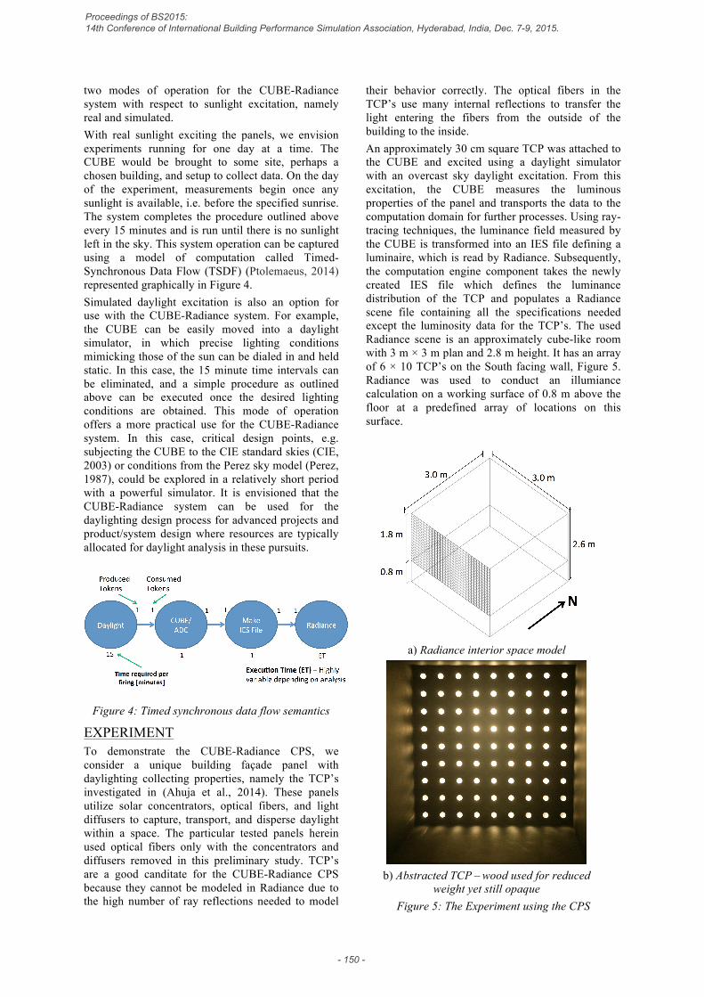
their behavior correctly. The optical fibers in the TCP’s use many internal reflections to transfer the light entering the fibers from the outside of the building to the inside. An approximately 30 cm square TCP was attached to the CUBE and excited using a daylight simulator with an overcast sky daylight excitation. From this excitation, the CUBE measures the luminous properties of the panel and transports the data to the computation domain for further processes. Using ray-tracing techniques, the luminance field measured by the CUBE is transformed into an IES file defining a luminaire, which is read by Radiance. Subsequently, the computation engine component takes the newly created IES file which defines the luminance distribution of the TCP and populates a Radiance scene file containing all the specifications needed except the luminosity data for the TCP’s. The used Radiance scene is an approximately cube-like room with 3 m × 3 m plan and 2.8 m height. It has an array of 6 × 10 TCP’s on the South facing wall, Figure 5. Radiance was used to conduct an illumiance calculation on a working surface of 0.8 m above the floor at a predefined array of locations on this surface.
a) Radiance interior space model
b) Abstracted TCP – wood used for reduced
weight yet still opaque Figure 5: The Experiment using the CPS
Proceedings of BS2015: 14th Conference of International Building Performance Simulation Association, Hyderabad, India, Dec. 7-9, 2015.
- 150 -

Due to the daylight simulator using an overcast sky as excitation, an assumption of uniform light exiting the optical fibers into the space, i.e. a lambertian light source, is adopted. While this experiment only shows a small subset of the CUBE-Radiance CPS’s full experimental power with respect to nonuniform luminance façade panels, for this presentation of the CUBE-Radiance CPS, it does show its full operational semantics in simulated daylight excitation mode.
RESULTS ANALYSIS Figure 6 shows the horizontal illuminance calculated by Radiance for the model in Figure 5a. Programmatically in Radiance, the illuminance is solved for at a set of fixed locations on a grid located 0.8 m above the floor. These locations and their corresponding illuminance values are represented using discrete values that can be converted into a contour plot. The illuminance is about 4.0 lux near the TCP bearing wall (South facing façade) and drops to about 2.7 lux at the opposite side of the space. While this illuminance is low, when considering intuitively the only light source in the room is an array of optical fibers transferring light from an overcast outdoor environment, it does however seem reasonable.
Figure 6: Radiance analysis – horizontal illuminance
[lux] on a working plane at 0.8 m above floor
FUTURE WORK The future work with the CUBE-Radiance CPS is to deploy the CUBE for longer duration measurements under real sunlight conditions for full days during the year. This will allow for the evaluation of daylight harvesting façade contributions to the indoor built environment’s illumination throughout the course of a full day. Because in reality the sun position is constantly changing, we expect to conduct this study
for several days throught the year. Therefore, we feel this analysis offers a powerful insight for designs using novel daylight harvesting façades. Practically, if the data are collected for solstices and equinoxes, a period of only 3 days of data (because the two equinoxes have the same sun patterns), the extreme behaviors are captured and can be used in design. Another future work is to “close-the-loop” of the CUBE-Radiance CPS by using the results of the Radiance simulation to augment the façade panel under test, Figure 7. For example, suppose the façade panel under test has some augmentable component like a shade or adjustable daylight concentrator. The panel excitation and data collection would proceed as defined above. However, depending on the results of Radiance simulation (this could be several analyses as the full Radiance suite is at the user’s disposal), the analysis results are fed into a controller to manipulate the shades or the concentrators of the façade panels. In this manner, an office space with a novel daylight collecting façade can be adjusted to attenuate daylight admitance. If excessive illumiance is calculated by Radiance on a workplane surface during one step, the CUBE can automatically manipulate the the façade to adjust the daylight admitted into the space. This functionality allows for testing of not only novel daylight harvesting façade panels, but also control algorithms for their operation.
Figure 7: CUBE-Radiance CPS architecture
featuring “closed-loop” functionality Further work in validating the above technique using full-scale experimental techniques is also planned. The newly completed SinBerBEST Testbed and Daylight Emulator will play a crucial role in this work.
SUMMARY There are three main methods used in the analysis of indoor lighting designs: Experimental, Numerical, and Simplified. Each method comes with advantages and disadvantages including cost, time, and resources. Presented here is a novel method that combines experimental and numerical methods, providing a new method of analysis benefiting from
Proceedings of BS2015: 14th Conference of International Building Performance Simulation Association, Hyderabad, India, Dec. 7-9, 2015.
- 151 -

the ease of use of the numerical methods and expressiveness and accuracy of real world measurements from the experimental methods. The machinery associated with this new method can be classified as a cyber-physical system and thus expands the domain of a well-established field of research. A proof-of-concept simulation is presented and the future directions of the work are stated.
ACKNOWLEDGEMENTS The authors thank Pierre Lemarchand for assistance with Radiance and Aashish Ahuja and Nuria Casquero-Modrego for helpful comments concerning luminance. Selim Günay also offered much appreciated technical advice. The presented research was funded by the Republic of Singapore’s National Research Foundation through a grant to the Berkeley Education Alliance for Research in Singapore (BEARS) for Singapore-Berkeley Building Efficiency and Sustainability in the Tropics (SinBerBEST) program. BEARS has been established by the University of California, Berkeley, as a center for intellectual excellence in research and education in Singapore.
REFERENCES
Ahuja, A. Mosalam, K. and Zohdi, T. (2014). Computational Modeling of Translucent
Concrete Panels. J. Archit. Eng., 10.1061/(ASCE)AE. 1943 5568.0000167, B4014008
Ashdown, I. (1993a). Near-field photometry: A new approach. Journal of the Illuminating Engineering Society, 22(1), 163-180.
Ashdown, I. (1993b, August). Near-field photometry in practice. In IESNA Annual Conference Technical Papers (pp. 413-425).
Bellia, L., Cesarano, A., Minichiello, F., & Sibilio, S. (2002). Setting up a CCD photometer for lighting research and design. Building and Environment, 37(11), 1099-1106.
Bodart, M., & De Herde, A. (2002). Global energy savings in offices buildings by the use of daylighting. Energy and Buildings, 34(5), 421-429.
Bodart, M., Deneyer, A., De Herde, A., & Wouters, P. (2007). A guide for building daylight scale models. Architectural Science Review, 50(1), 31-36.
Brendecke, T., & Kucukay, F. (2002). Virtual real- time environment for automatic-transmission control units in the form of hardware-in-the-loop. International journal of vehicle design, 28(1), 84-102.
CIE S 011/E. 2003. Spatial Distribution of Daylight – CIE Standard General Sky. Standard, CIE central bureau: Vienna.
CIE (1926). Commission Internationale de l'Eclairage proceedings, 1924. Cambridge University Press, Cambridge.
Cole Jr, J. S., & Jolly, A. C. (1996, May). Hardware- in-the-loop simulation at the US Army Missile Command. In Technologies for Synthetic Environments: Hardware-in-the-Loop Testing (Vol. 2741, pp. 14-19).
DiLaura, D. L. (2011). IES handbook 10th edition. Ecotect – (2015) Sustainable Building Design
Software – Autodesk (Ecotect) http://usa.autodesk.com/ecotect-analysis/ Edwards, L., & Torcellini, P. A. (2002). A literature
review of the effects of natural light on building occupants (p. 59). Golden, CO: National Renewable Energy Laboratory.
Fakra, A. H., Miranville, F., Boyer, H., & Guichard, S. (2011). Development of a new model to predict indoor daylighting: Integration in CODYRUN software and validation. Energy Conversion and Management, 52(7), 2724-2734.
FLEXLAB. https://flexlab.lbl.org. Isermann, R., Schaffnit, J., & Sinsel, S. (1999).
Hardware-in-the-loop simulation for the design and testing of engine-control systems. Control Engineering Practice, 7(5), 643-653.
Koren, B. S. (2010). Louvre Abu Dhabi 1/33— Fabrication of a large-scale physical light-test model. Advances in Architectural Geometry 2010, 163-174.
Krarti, M., Erickson, P. M., & Hillman, T. C. (2005). A simplified method to estimate energy savings of artificial lighting use from daylighting. Building and Environment, 40(6), 747-754.
Lee, E. A. (2015). The Past, Present and Future of Cyber-Physical Systems: A Focus on Models. Sensors, 15(3), 4837-4869.
Palmer, J. M., & Grant, B. G. (2010). The art of radiometry. Bellingham: SPIE Press.
Perez, R., Seals, R., Ineichen, P., Stewart, R., & Menicucci, D. (1987). A new simplified version of the Perez diffuse irradiance model for tilted surfaces. Solar energy, 39(3), 221-231.
Ptolemaeus, C. (2014). System Design, Modeling, and Simulation: Using Ptolemy II.
Elkhoraibi, T., & Mosalam, K.M. (2007). Towards error-free hybrid simulation using mixed variables. Earthquake Engineering and Structural Dynamics, 36(11), 1497-1522.
Ward, G. J. (1994, July). The RADIANCE lighting simulation and rendering system. In Proceedings of the 21st annual conference on Computer graphics and interactive techniques (pp. 459-472)
Proceedings of BS2015: 14th Conference of International Building Performance Simulation Association, Hyderabad, India, Dec. 7-9, 2015.
- 152 -