Embed Size (px)
Citation preview
STANGE, W. and KING, R.P. A population balance approach to the modelling of the CIP process. APCOM 87. Proceedings of the Twentieth International Symposium on the Application of Computers and Mathematics
in the Mineral Industries. Volume 2: Metallurgy. Johannesburg, SAIMM, 1987. pp. 209-221.
A Population Balance Approach to the Modelling of the CIP Process
W. STANGE and R.P. KING
Department of Metallurgy and Materials Engineering, University of the Witwatersrand, Johannesburg
A method, based on the macroscopic population balance equation allowing the dynamic simulation of a multi stage adsorption plant given an arbitrary rate expression, is described. The partial differential equations resulting from this method are simplified using the method of characteristics. The simplified equations can then be solved using standard ODE integration techniques. The procedure is illustrated by means of data typical of a CIP application.
Requirements for data structures which allow the incorporation of the carbon-in-pulp (CIP) model (and other unit models) into a general metallurgical simulator are described. Based on these considerations, it is concluded that more generality in the description of distributed quantities such as loading and particle size is provided by the use of mass density at fixed class boundaries, rather than discrete masses within fixed classes as has hitherto been
used by ore-dressing simulators.
Introduction
unit processes has been done, (12) no A number of metallurgical simulation
packages exist although many of these are
not general simulation packages which
allow the simulation of arbitrary process
flowsheets. Packages which allow the
simulation of arbitrarily complex ore
dressing flowsheets have been described,
(1) and some packages which permit the
simulation of ore-dressing and hydro
metallurgical flowsheets using simplistic
models are also available. (2)
common methodology such as that used for
ore-dressing modelling exists.
Cilliers (11) has developed a
flexible simulator executive incorporating
data structures which are extendable and
versatile enough to describe all possible
substream types found in hydro-
metallurgical flowsheets. Powerful tearing
and ordering routines which are able to
cope with the complex recycles present in
these flowsheets were also developed.
(11) Although some excellent work in the
modelling of particular hydrometallurgical
This paper describes the modelling of
the CIP process. The techniques developed
to model this process may serve to
illustrate some methods which may be used
in the modelling of hydrometallurgical
processes such that the resulting models
can be used in a general simulator.
Owing to the economic importance of the
CIP process in South Africa as well as in
other gold producing countries, the
benefits which an accurate, flexible model
could have for the design and optimization
of CIP plants are obvious. This is one
reason why a CIP modelling exercise was
chosen. The other is that the CIP process
is complex and any methods developed for
its modelling are likely to have
significant implications for the
development of simulation techniques for
A POPULA nON APPROACH TO MODELLING THE CIP PROCESS 209
hydrometallurgical unit processes. This
would facilitate
simulator which
the
is
development of a
able to handle
metallurgical flowsheets containing both
ore-dressing and hydrometallurgical unit
processes.
Ore-dressing simulator data structures
The success realized by available
ore-dressing simulators
the more simplistic
is perhaps due to
models of unit
procesess (as compared to, say, hydro-
metallurgy) wi th which they have to
contend. There is also only the ore phase
which needs to be described effectively.
In general, only the mass flowrate of the
aqueous phase is needed. This has allowed
the development of data structures which
represent the properties of the process
streams in great detail. For
ore-dressing, attention has focused on the
description of the particulate nature of
In the well known ore-dressing the ore.
simulator
dimensional
MODSIM,
matrix
(1) a
represents
three
the
distributed properties of particle size,
grade and 'flotability' as a discrete
distribution for each process stream. Each
mathematical model in the simulator thus
operates on a well defined stream data
structure, transforming the discrete feed
distribution
distributions
into
for the
the appropriate
unit products.
Calculation may then proceed easily in
sequential-modular fashion.
Considerable success has been obtained
using this method, and as most
ore-dressing models described in the
literature use this discrete method for
representing the distributed ore
properties, it is easy to add ne,.;
process models to such a simulator.
unit
The development of techniques for the modelling of the CIP process
Although significant research has been
conducted on the derivation of an
210
appropriate rate expression for the
adsorption of gold onto activated carbon,
(3,4,5) not much work concerning the
insertion of these rate expressions into
the equipment mass -balance has b,een done.
It is normal to develop particular methods
appropriate for the rate expression used.
(4,5) This is obviously unsatisfactory
if the models developed are to be embedded
in a general· simulator. The CIP model
should be capable of accepting a
user-supplied rate expression. The level
of complexity (in the rate expression) may
thus be chosen to suit the amount and type
of data to which the user has access.
Quantities which have a major effect on
the rate of adsorption of gold onto carbon
are bulk solution tenor, carbon particle
size and gold loading on the carbon. Each
rate expression includes these variables
(or closely related quantities) in a
specific functional form to predict the
rate of loading at any time. Due to the
nature of the carbon used in CIP plants
and the way in which it is manufactured,
the carbon particles are not equally sized
but a distribution of sizes exists. Carbon
is transferred countercurrent to the flow
of the pulp by moving a certain fraction
of the carbon in each contactor forward to
the next contactor periodically. This
leads to a distribution of loaclings (which
can be expected to be different for each
particle size) in each contactor. Thus
two distributed quantities exist which
strongly influence the rate of adsorption.
These must be dealt with appropriately in
any attempt to model the CIP situation.
Williams and Glasser (5) have shown
that if the rate expression is linear in
the gold loading term, average loading
values may be used. in both the carbon mass
balance and the solution mass balance. Van
Deventer (4) used a discrete density
function to describe the distribution of
loadings. Although good agreement bet,.;een
METALLURGY: GOLD PROCESSING
predicted and experimental data was
obtained, it would be difficult to use
this method to simulate the general case
i.e. when carbon flows into and out of the
contactor and carbon abrasion and breakage
takes place during adsorption.
Due to the power and flexibility of the
method, this work was based on the
population balance technique.
The population balance technique
The population balance technique is a
general method used to analyse particulate
systems. It has been used to model
erystallizers (6) as well as minerals
processing
comminution,
unit (8)
operations
flotation,
such as (10) and
leaching. (7) Various examples of
use of population
minerals processing
Herbst. (9)
balance models
are provided
the
in
by
Although excellent explanations of the
derivation of the population balance
equation can be found in the above
references, a short review is in order for
those readers not familiar with the
relevant literature.
Although derived from the same
mathematical equations, two forms of the
population balance exist: the macroscopic
and microscopic forms. The macroscopic
version is used when the behaviour of each
particle is not influenced by its position
in the reactor vessel. This form is
normally used for systems where it can be
assumed that the particulate phase is well
mixed, such as leaching and CIP. The
microscopic form is used to describe
systems where the particle behaviour is
influenced by its spatial coordinates, for
example in a plug-flow reactor. Only the
macroscopic population balance equation
will be discussed in this paper as it is
assumed that the carbon phase in an
adsorption vessel is well mixed.
A particle is considered to have a set
of These may
be properties such as particle size,
unreacted core size (shrinking core
leaching model), the number of radicals in
a polymer, or the loading of gold on a
carbon particle. The continuous rate of
change of each property is defined by 1/ i
dZjdt.
1II(Zl,Z2'" ,Zj)
density function
is a
defined
population
so that
represents
the number of particles per unit volume,
which have property 1 in the range Zl to
Zl+~Zl' property 2 in the range Z2 to
Z2+~Z2 and so on.
A number balance (9) then leads to
the macroscopic population balance
equation :
feeds a [V(t)lII]
at = '\ F~n lII~n L l l
i=l
J
+V(t) [(B-D) I j=l
For the CIP case the
[1]
distributed
quantities are loading y and particle size
8. Thus define 1II(y,8,t)dy d8 as the number
of particles having loading between y and
y+~y and particle size between 8 and 8+~8
at time t, per unit volume of carbon in
the contactor. The property velocities are
thus:
Qy dt
d8 dt
R(y,C,8)
The following conditions are assumed to
exist during an adsorption cycle
- No carbon flows into or out of any of
the contactors.
=> Fin = Fout = 0
=> Vet) = Constant
A POPULATION APPROACH TO MODELLING THE CIP PROCESS 211
No breakage or attrition of carbon
occurs.
=> B = D
=> dS/dt
The first assumption is restrictive in
that, in general carbon may flow into or
out of a contactor o\ving to screen leaks,
spills or carbon transfer. This may be
accommodated easily in the macroscopic
equation. In this paper the simple case
will be developed so as not to make the
development more complex than necessary.
The first assumption is thus not a
limitation of the method but is used
merely for convenience in this particular
case. It can be seen that if functional
forms for 1.12' Band D exist, then the
macroscopic equation could be used to
model the industrial-scale adsorption
process realistically i. e. for the case
where carbon abrasion and breakage as well
as carbon flow into and out of a contactor
takes place.
Equation [1] for the assumptions made
can thus be written for each adsorption
stage n as
[2]
As it has been assumed that no size
degradation occurs, it is possible to
substitute the more convenient mass
Pn(y,S,t)dy dS is
thus the mass of carbon in the contactor
having loading between y and y+~y and size
between S and S+~S at time t. It is easily
shown that [2] can be written as
[ 3]
Equation [3] is a first-order PDE which
212
describes the movement of the carbon
loading and size distribution function in
each stage with time. This equation must
be solved simultaneously with the liquid
mass balance which can be written as
follows (assuming perfect mixing, and that
no leaching takes place)
1 V
s
00 00
II o 0
P (y,S,t) R(y,C ,S)dy dS n n
[4]
The Equations [3] and [4] define
completely the dynamic behaviour of a CIP
plant subj ect to the assumptions stated
above.
Methods of solution
The system of Equations [3] and [4] can be
simplified using the method of
characteristics. (13) This method finds
directions in the relevant plane(s) which
transforms the integration of a system of
PDEs into the integration of a system of
ODEs. Suitable methods for integrating
ODEs can then be applied, preferably
algorithms which adjust the step size to
keep the error below a maximum bound such
as that described by Fehlberg. (14)
Applying the method of characteristics
to the system of Equations [3] and [4],
the characteristic directions are given
by :
[5]
[ 6]
Along these directions the equations to
be integrated are :
dPn
] = _ P aR(y,Cn,S)
dt I n ay [7]
METALLURGY: GOLD PROCESSING
dC nJ = Q (C - C ) dt 11 Vs n-l n
co co
1 V
s J J P (y,o,t) R(y,C ,o)dy do n n
o 0 [ 8]
The system of equations to be solved
are thus [5 ], [7], [ 8] with the
appropriate initial conditions.
Carbon streams data structures suitable for use in a general simulator
Any general simulator must be able to
~epresent distributed properties in such a
way that the data for all streams is
'indexed' by the same fixed class
boundaries. For example, in an ore-
dressing simulator such as MODSIM, the
contents of size class 3, in any stream,
may refer to the mass of particles in that
stream having a representative size of 300
~m. The models transform the contents of
these classes, but do not change the
'index' values of any classes.
When transferring carbon in a CIP
plant, a mixing operation is carried out,
with a fraction of the carbon in two
adjacent stages being mixed together. In
order to facilitate the simulation of this
mixing operation, the distributed
properties (loading, size) of the carbon
in each stage must be indexed by the same
fixed class boundaries. Thus loading
class 4, size class 3 in contactors 1..N
must all represent the mass or number
density of carbon in each contactor having
say loading 300 g/ton and particle size
1.5mm. This is even more important if the
flowsheet to be simulated contains other
carbon handling units, for example an
elution column, or the more complex CIP
case where flow of carbon into and out of
the contactor (owing to carbon transfer
and/or spills) is modelled.
The elution and CIP mathematical models
are then able to operate on the streams
data using a common 'index' which needs to
be stored only once for the entire
flowsheet, and not for each stream.
Considering the number of classes which
may be needed to obtain an accurate
simulation,
significant
requirements.
this obviously
savings in
leads to
memory
There are two possible methods for
implementing fixed class stream storage
for the particulate phase. One is to use
discrete masses at fixed representative
class values by discretizing the
population balance partial differential
equation. A good example of this is the
way in which the PDE arising from the
breakage and selection comminution model
is discretized. Ore-dressing simulators
such as MODSIM then store the actual mass
in each class in each stream. However,
for certain models such as the CIP model
(see Equation [1]) it may be necessary to
approximate a partial derivative using
finite differences if the PDE is to be
discretised. Finite difference methods are
not suitable if discontinuities exist in
the density function, (15) and
discontinuities may easily occur in the
initial conditions for the population
balance Equation [1]. These methods do not
propagate the discontinuity, but "smudge"
the area near the discontinuity.
The other method is to use mass or
number density at fixed class bounds.
Sepulveda (7) has used this method in
the numerical techniques that he has
developed to solve rigid models for the
leaching process.
The approach adopted in this work was
to use mass density at fixed class bounds.
This was done for the following reasons :
a) The method of characteristics can then
be used to solve the CIP model with any
rate expression. This can be seen from
Equations [5] , [7] and [8]. This
method can be used for rate expressions
A POPULATION APPROACH TO MODELLING THE CIP PROCESS 213
of any complexity, even when a system
of differential equations such as those
developed by Van Deventer (4)
describe the rate of adsorbtion. A
sophisticated ODE solver has been
designed, and this forms the basis of
the CIP model. This solver is based on
the work by Fehlberg (14) which
allows an estimate of the truncation
error to be made at each integration
step. Step length control is
implemented
by Thomas
using (17)
methods
This
recommended
ODE solver
allows the solution
differential equations
rate expression as
characteristic equations.
of all
defining
well as
the
the
the
b) Sufficient generality is provided. The
model can be extended to cope with the
general CIP case (where carbon may flow
into and out of a contactor) and still
use any rate expression.
c) The population balance method is
powerful enough to provide the
framework for the modelling of many
other unit processes. These models
would require the distribution to be
described as discrete masses or mass
densities, and as it may not always be
possible to discretize the population
balance PDE, the use of mass density
provides more generality. Mass or
number density thus provides a common
basis for future model development,
enabling program modules and methods to
be developed which can be utilized by
all unit models.
Implementation using the method of characteristics
Using
consists
characteristics, the
of integrating Equation
problem
[5]
the chosen number of characteristics.
for
The
number of characteristics used depends on
the accuracy required. Ten to two hundred
characteristics per contactor were used,
and it was found that forty
214
characteristics per contactor provided
acceptable accuracy for the case
simulated. The number of characteristics
chosen determines the number of equations
to be solved. Although microcomputers
provide sufficient storage capability even
when two hundred characteristics are used,
the numeric processing capabilities of
most microcomputers are such that times in
the order of hours would be needed to
solve the large system of ODEs which
define this problem. This is made worse
by the fact that the system may need to be
solved many times, starting at some
initial condition, before a pseudo-steady
state is achieved. This makes the use of
(most) microcomputers to solve the problem
impractical at this stage.
The initial value for each
characteristic is the relevant fixed class
boundary value. The characteristics
define the traj ectory of a particle which
has an initial loading equal to a class
boundary value. Equation [8] needs to be
integrated along each characteristic, with
the initial conditions being the initial
number density at the appropriate class
boundary. Equation [7] also needs to be
integrated simultaneously
[8] . As the y values
with
defined
[5]
by
and
the
integration of [5] are not equally spaced
the trapezoidal rule was used'to evaluate
the integral in [7].
The major problem resulting from the
use of characteristics is that at the end
of the adsorption cycle, P is defined at
the y values calculated by the integration
of [5], not at the fixed class boundaries.
An interpolation procedure was thus
developed which enabled the values of P at
the fixed class bounds to be found from
the values of P defined by [5] and [8] at
the end of the adsorption cycle.
An appropriate interpolatiou technique
The requirement for the interpolation
technique was that the integral :
METALLURGY: GOLD PROCESSING
I=IIp(y,o,t)dY do
evaluated at the y, 0 ,P values defined by
the integration of Equations [5] and [8],
be the same as that evaluated at the fixed
class bounds. This is mos t critical as
the above integral is the total mass of
particles in the contactor at time t and
this quantity cannot be in error.
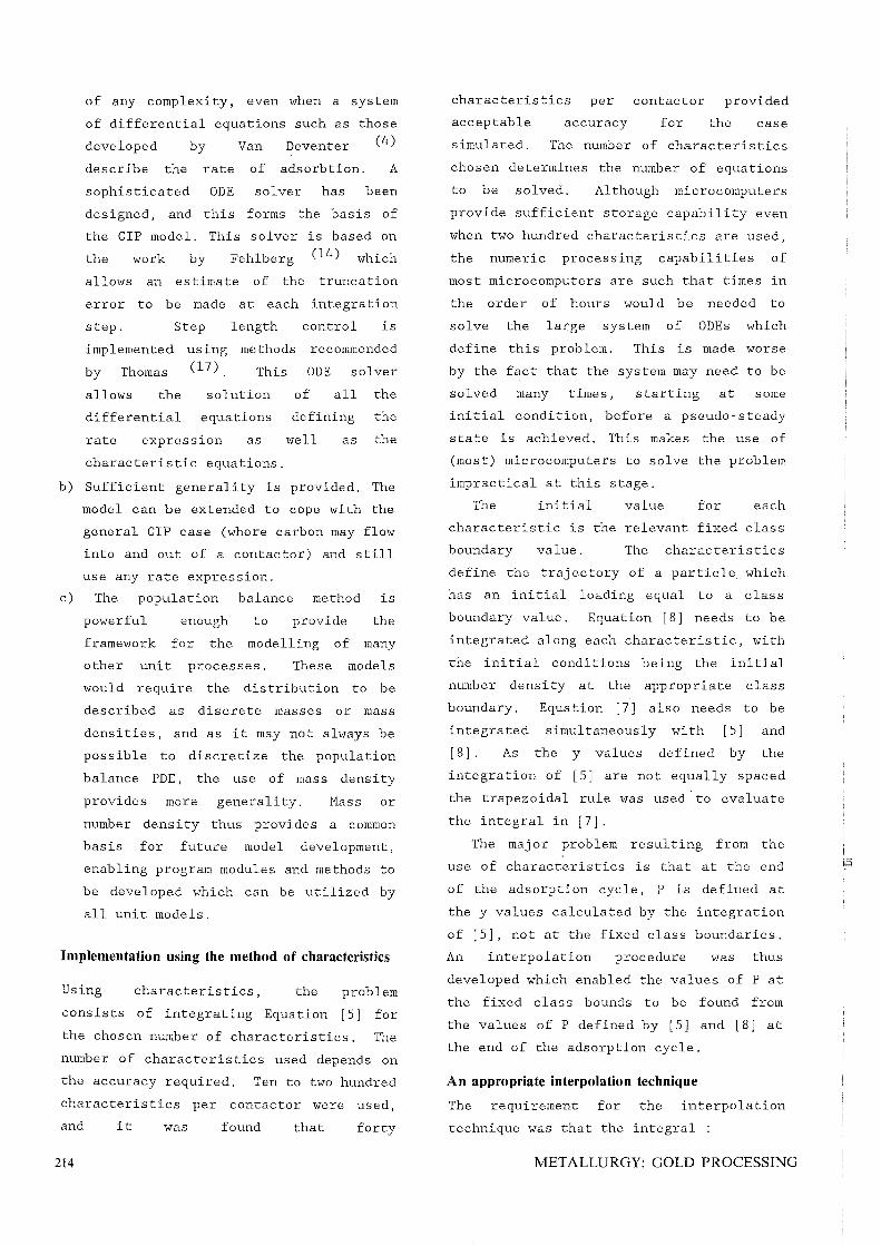
Although standard linear and polynomial
interpolation techniques were tried, none
met the above requirement. Accordingly, a
method based on constrained minimization
was developed. The constraint in the
interpolation method developed is that the
integral calculated at the fixed class
bounds be equal to I i.e. the total mass
of carbon in the contactor. The quantity
to be minimized is the sum of the relative
differences between the P values at the
fixed class bounds that satisfy the
constraint and those P values determined
300000
at the fixed boundaries by linear
interpolation from the values defined by
integration along the characteristics.
This allows the constraint to be met while
preserving the shape of the P
distribution. A set of equations in P at
the fixed class bounds is set up. These
may be solved simply without using any
complex numerical techniques. Figure 1
shows an example of results obtained using
this method.
Simulation results
Although many simulations could be run
showing the effect of various parameters
on CIP plant performance, this work is
primarily concerned with the description
of changes in the loading distribution
during adsorption. Thus only examples
illustrating this feature will be
presented.
All simulations were performed using
N 200000 Original
Interpolated
u m b e r
D e n s 100000 i t Y
o o 1000 2000 3000
Loading g/ton
FIGURE 1. Original and interpolated distributions
A POPULA nON APPROACH TO MODELLING THE CIP PROCESS 215
the (16)
rate
and
expression described by Menne
used by Glasser and Williams
(5) in their work. As the dependency of
the rate expression parameters on carbon
particle size have not been established,
only one size class was used in all
simulations. The following parameter
values were used :
kl 0,012
k2 0,0019
* 3328 ton- l y g
Mc 4,32 tons
Vs 75 m3
Q 75 m3 hour- l
N 5
Cin = 1,9 g m- 3
Cycle Time = 24 hours
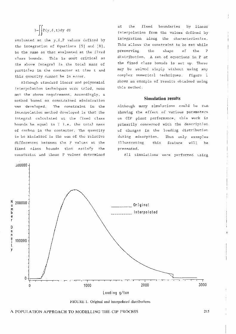
The rate expression used has the
functional form
R=kl C (/' - y) - k2 y
0.012 i 0.011
0.010
0.009
1.4 0.008 a s 0.007 s o 0.006 e n 0.005, s I 0.004
Y 0.003
0.002
0.001
0.000
o 1000
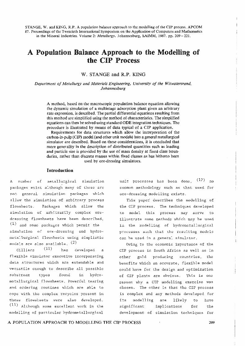
Figure 2 illustrates the
used as initial conditions
contactors.
distribution
in all CIP
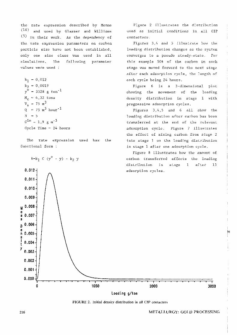
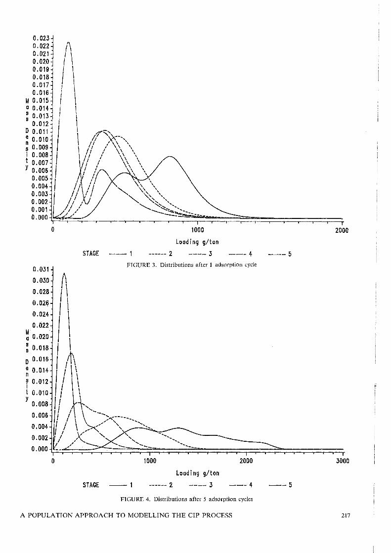
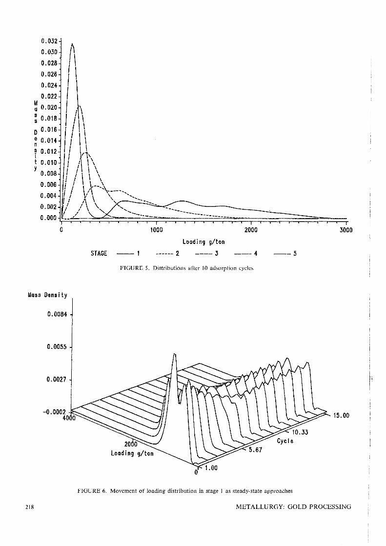
Figures 3,4 and 5 illustrate how the
loading distribution changes as the system
converges to a pseudo steady- state. For
this example 50% of the carbon in each
stage was moved forward to the next stage
after each adsorption cycle, the length of
each cycle being 24 hours.
Figure 6 is a 3-dimensional plot
showing the movement of the loading
density distribution in stage 1 with
progressive adsorption cycles.
Figures 3,4,5 and 6 all show the
loading distribution after carbon has been
transferred at the end of the relevant
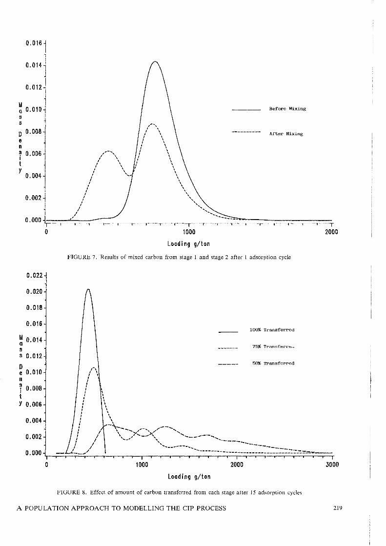
adsorption cycle. Figure 7 illustrates
the effect of mixing carbon from stage 2
into stage 1 on the loading distribution
in stage 1 after one adsorption cycle.
Figure 8 illustrates how the amount of
carbon transferred affects the loading
distribution in stage 1 after 15
adsorption cycles.
2000 3000
Loading g/ton
FIGURE 2. Initial density distribution in all CIP contactors
216 METALLURGY: GOLD PROCESSING
0.023 1 0.
0221 I~ 0.021 \ 0.020 I 0.019j \ 0.018~ I 0.017j I \ 0.016-] I; \
lA 0.015 ~
: 0.013 I \ a 0.01411
\
0.012 j \ DO. 0 11 I I d''.' e ' \ // \'-<-"" ~ ~: ~~~ 1 ( \ 1/ ,/ \ \ ' i O. 008) ( 1/,' to. 007 ~ / I "
Y ~:~~~ (I // j~ 0.004 / I '/ 0.003 ( 1/ \ / 0.002 1/ ,YJ
/ I " 0.001 / I ' 0.000 .I /
o
STAGE ~~ 1 ------ 2
1000
Loading g/ton
---- 3 ---4
0.031 FIGURE 3. Distributions after 1 adsorption cycle
0.030 {\
o .028 I \ 0.026 (\
0.024 I \ 0.022 \
~ 0.020 (
: 0.018 ( \
D 0.016 ( Ip\
: 0.014 1 I \ \ f 0.012 I / \ \\ t 0.010 I ~ y 0.008 /' ~"
/' I \ '-_ a . 006 , I \ .... , ...... -- ___ ... , / \ """ , -- ...
2000
--5
~:~~: fl, / V'''><~''~ "" ........................ ... I ~~, " ............ ~-__
0.000 ~/~-_;<=,,~/~.=,--~~=.~=-~~~,;-=-~-~~~= ...... ~ ... ~ ... -=-~~;=;=~~~~~~~~~=;=;~~ o 1000 2000 3000
Loading g/ton
STAGE - 1 ------ 2 ---- 3 --- 4 --5
FIGURE 4. Distributions after 5 adsorption cycles
A POPULATION APPROACH TO MODELLING THE CIP PROCESS 217
G 1000 2000 3000
Loading g/ton
STAGE -- 1 ------ 2 ---- 3 ---4 --5
FIGURE 5. Distributions after 10 adsorption cycles
Uass Dens i ty
0.0084
0.0055
0.0027
15.00 -0.0002 40 0
FIGURE 6. Movement of loading distribution in stage 1 as steady-state approaches
218 METALLURGY: GOLD PROCESSING
0.022
0.020
0.018
0.016
~ 0.014 s s 0.012
D e 0.010 n S
0.008 i t Y 0.006
0.004
0.002
0.000
0
1000
Loading g/ton
Before Mixing
After Mixing
FIGURE 7. Results of mixed carbon from stage 1 and stage 2 after 1 adsorption cycle
I I I I I ,
I I I I I I , , , , , , , , , , , , ,
I
lA, \ \
I I
I I
\ \ \ \ \ \ \ \ \ \ \ \ ,
-'\-..... - ---- ...... \ -...... "'"",. .... , ,/'" " \, ,,' ...... _.,.>'" ............ _----' ......
....... " "... ......._-----
100% Transferred
75% Transf'err,,~
50% Transferred
I 2000
I / I / --'"
.... -- -----... __ ...... ... ... -...... --------------------------::-::--:':"::.=~ .... -1000 2000 3000
Loading g/ton
FIGURE 8. Effect of amount of carbon transferred from each stage after 15 adsorption cycles
A POPULA nON APPROACH TO MODELLING THE CIP PROCESS 219
Conclusions
A powerful technique, allowing the dynamic
simulation of a CIP plant using any rate
expression has been developed. This makes
the simulation of RIP (resin in pulp)
simple if an appropriate rate expression
for the adsorption of gold onto resin is
available, as the RIP equipment geometry
is very similar to that of CIP.
The mass balance for the carbon phase
was derived using the macroscopic
population balance. The resulting system
of equations was simplified by use of the
method of characteristics and solved by
conventional ODE numerical techniques.
Fixed class boundaries, together with
mass density were used for the
representation of the distributed carbon
properties instead of the more commonly
used discrete masses in fixed classes.
This was done to provide maximum model
generality and extendability.
The methods developed may be used as a
basis for the development of other dynamic
hydrometallurgical models, particularly
other units which are found in resin or
carbon based adsorption flowsheets such as
elution.
220
1Jr
P
B
Notation
Number density function.
Mass density function.
Birth rate function.
D Death rate function.
v Volume of particulate phase.
Mc Mass of carbon in a contactor.
Vs Solution volume in a contactor.
F = Volumetric flowrate of particulate
phase.
Q
N
Y
d
C
Volumetric flowrate of aqueous
phase.
Number of CIP stages.
Average gold loading on carbon
particle.
Carbon particle size.
Gold concentration in aqueous
phase.
R
n
Rate of loading of gold onto a
carbon particle.
Subscripts
Stage index.
References
1. FORD, M.A. and KING,R.P. The
simulation of ore-dressing plants.
Int.J.Hiner. Process. vol.12 1984.
pp. 285-304.
2. RI CHARDS ON , J.M. COLES, D.R. and WHITE,
J.W. Flexmet: A computer-aided and
flexible metallurgical technique for
steady-state flowsheet simulation.
Engineering and Hining Journal.
vol.82 no. 10, 1981. ~p.88-97.
3. JOHNS, M.W. Model application.
Lecture 5, Carbon School, HINTEK.
February 1986.
4. VAN DEVENTER, J.S.J. Kinetic model for
the adsorption of metal cyanides on
activated charcoal. 1984. Ph.D. thesis,
University of Stellenbosch.
5. WILLIAMS, D.F. and GLASSER, D. The
modelling and simulation of processes
for the adsorption of gold by charcoal.
J. S. Afr. Inst. Hin. Hetall.
vol.85, no. 8, 1985. pp.237-243.
6. RANDOLH, A:D. and LARSON, M. Theory
of Particulate Processes. New York,
Academic Press, 1971.
7. SEPULVEDA, J.E, A fundamental approach
to the design and optimization of
multistage, agitated leaching systems.
1981. Ph. D. thesis, University Of
Utah.
8. HERBST, J.A and FUERSTENAU, D.W.
Scale-up procedure for continous
grinding mill design using population
METALLURGY: GOLD PROCESSING
balance models. Int.J.Miner.
Process. vol.7 1980. pp. 1-31.
9. HERBST, J.A. Rate processes in
multiparticle metallurgical systems.
In: Rate Processes in Extractive
Metallurgy. Sohn, H.Y. and
Wadsworth, M.E. New York, Plenum
Press, 1978. pp.53-lll.
10.BASCUR, O.A. and HERBST, J.A. Dynamic
modelling of a flotation cell with a
view toward automatic control. CIM
XIV International Mineral Processing
Conference. Toronto, 1982.
11.CILLIERS, J.J. Hydrometallurgical
simulation : A viable program
structure. 1986. M.Sc. dissertation.
University of The Witwatersrand,
Johannesburg.
l2.SEPULVEDA, J.E. and HERBST, J.A. A
population balance approach to the
modeling of multistage continuous
leaching systems. Fundamental
Aspects of Hydrometallurgical
Processes. AIChE Symposium Series.
vol.74, no. 173. pp.4l-65.
l3.AMES, W.F. Numerical Methods for
Partial Differential Equations. 2nd
ed. New York, Academic Press, 1977.
l4.FEHLBERG, E. Klassiche runge-kutta
formeln vierter und niedrigerer
ordnung mit schrittweiten-controlle
und ihre anwendung auf
warmeleitungsprobleme. Computing.
vol.6 1970. pp.6l-7l.
l5.SMITH, G.D. Hyberbolic equations and
characteristics. In: Solution of
Partial Differential Equations
Finite Difference Methods. 3rd ed.
Oxford, Clarendon Press, 1985.
pp.143-20S.
16.MENNE, D. Predicting and assessing
carbon-in-pulp circuit performance.
CIM XIV International Mineral
Processing Conference. Toronto, 1982.
l7.THOMAS, B. The Runge-Kutta Methods.
Byte. vol.ll, number 4, 1986.
pp.19l-210.
A POPULATION APPROACH TO MODELLING THE CIP PROCESS 221