Embed Size (px)
Citation preview
Mechatronics 24 (2014) 41–54
Contents lists available at ScienceDirect
Mechatronics
journal homepage: www.elsevier .com/ locate/mechatronics
A platform for aerial robotics research and demonstration: The FlyingMachine Arena
0957-4158/$ - see front matter � 2013 Elsevier Ltd. All rights reserved.http://dx.doi.org/10.1016/j.mechatronics.2013.11.006
⇑ Corresponding author. Tel.: +41 44 632 0608, mobile: +41 76 226 5145.E-mail address: [email protected] (S. Lupashin).
Sergei Lupashin ⇑, Markus Hehn, Mark W. Mueller, Angela P. Schoellig, Michael Sherback,Raffaello D’AndreaETH Zurich, Institute for Dynamic Systems and Control, Sonneggstrasse 3, ML K 36.2, Zurich, ZH 8092, Switzerland
a r t i c l e i n f o a b s t r a c t
Article history:Received 15 November 2012Accepted 15 November 2013Available online 10 January 2014
Keywords:Aerial roboticsQuadrocoptersRobotics testbedsNetworked control systems
The Flying Machine Arena is a platform for experiments and demonstrations with fleets of small flyingvehicles. It utilizes a distributed, modular architecture linked by robust communication layers. An esti-mation and control framework along with built-in system protection components enable prototypingof new control systems concepts and implementation of novel demonstrations. More recently, a mobileversion has been featured at several eminent public events. We describe the architecture of the Arenafrom the viewpoint of system robustness and its capability as a dual-purpose research and demonstrationplatform.
� 2013 Elsevier Ltd. All rights reserved.
1. Introduction
Dedicated multi-vehicle aerial robotics test beds such as [1–3]first appeared around a decade ago – the MIT Raven [1] test bedbeing one of the first described in literature. A number of researchresults have been enabled by such test beds such as aggressivemaneuvers [4], aerobatics [5,6], object manipulation [7,8], coordi-nated construction [9], and others, expanding the field of aerialrobotics at an impressive pace. Traditionally limited to scientificexperiments, these systems are now reaching wider audiences atinstallations such as the New Directors’ Showcase at Cannes [10],the outdoor aerial light show at Ars Electronica 2012 [11], andour own shows further detailed below.
Since 2007 we have been developing an aerial robotics test bedcalled the Flying Machine Arena (FMA) (Fig. 1). Our goal is to createsoftware and hardware infrastructure reliable and robust enoughfor regular public demos while also being sufficiently flexible forresearch use. Given the research context, it is natural that a systemlike the FMA undergoes continuous modification; yet to enablepublic demonstration the FMA also has to meet the conflictingrequirement of being a reliable, predictable system, operating ondemand and with little forewarning. To meet these opposingrequirements, the Arena has been created as a strictly modularizedplatform where flight-proven components are used for demonstra-tions as a complete flight-ready system, or, for research, in near-arbitrary combination with new, malleable experimental modules.
The FMA infrastructure is mostly vehicle-agnostic and a varietyof dynamic systems have taken advantage of the platform. How-ever, typical public FMA demos use small quadrocopters, mainlybecause of their unique combination of simplicity, robustness,and agility. Therefore algorithms and methodology in this workwill be presented in a generalized manner, though quadrocopterswill be used regularly to describe concrete details, with necessaryspecific equations listed in the appendices.
In addition to the quadrocopter-specific work, the FMA hasfound use in various other projects [12–14], mainly as a (i) distrib-uted rapid-prototyping environment and for (ii) performance vali-dation and evaluation. For example, a vision-based autonomousmulticopter [14] was flown in the FMA to collect ground truthlocalization data, taking advantage of the protected space, themotion capture system, and the networking middleware to simul-taneously collect data and to provide a backup failsafe controller incase the on-board autonomy failed.
In this work we take a different perspective from previous aerialrobotic test bed publications [1–3] and describe the FMA systemarchitecture (Section 2) and core components (Section 3) fromthe viewpoint of system robustness and dual-use capability. Notethat here the term ‘‘robustness’’ refers to the concept of resilienceof a system as a whole under stress and non-ideal subsystem per-formance. Again with a focus on resilience, we include a brief high-level analysis of key system performance characteristics inSection 4.
Public demonstrations enforce system robustness while dis-seminating research results without requiring further dedicatedand possibly distracting commitments such as challenges and
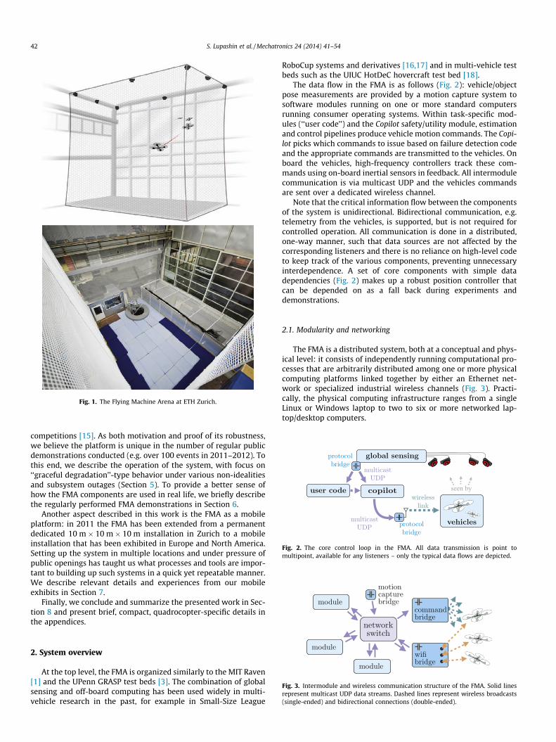
Fig. 1. The Flying Machine Arena at ETH Zurich.
Fig. 2. The core control loop in the FMA. All data transmission is point tomultipoint, available for any listeners – only the typical data flows are depicted.
42 S. Lupashin et al. / Mechatronics 24 (2014) 41–54
competitions [15]. As both motivation and proof of its robustness,we believe the platform is unique in the number of regular publicdemonstrations conducted (e.g. over 100 events in 2011–2012). Tothis end, we describe the operation of the system, with focus on‘‘graceful degradation’’-type behavior under various non-idealitiesand subsystem outages (Section 5). To provide a better sense ofhow the FMA components are used in real life, we briefly describethe regularly performed FMA demonstrations in Section 6.
Another aspect described in this work is the FMA as a mobileplatform: in 2011 the FMA has been extended from a permanentdedicated 10 m� 10 m� 10 m installation in Zurich to a mobileinstallation that has been exhibited in Europe and North America.Setting up the system in multiple locations and under pressure ofpublic openings has taught us what processes and tools are impor-tant to building up such systems in a quick yet repeatable manner.We describe relevant details and experiences from our mobileexhibits in Section 7.
Finally, we conclude and summarize the presented work in Sec-tion 8 and present brief, compact, quadrocopter-specific details inthe appendices.
Fig. 3. Intermodule and wireless communication structure of the FMA. Solid linesrepresent multicast UDP data streams. Dashed lines represent wireless broadcasts(single-ended) and bidirectional connections (double-ended).
2. System overview
At the top level, the FMA is organized similarly to the MIT Raven[1] and the UPenn GRASP test beds [3]. The combination of globalsensing and off-board computing has been used widely in multi-vehicle research in the past, for example in Small-Size League
RoboCup systems and derivatives [16,17] and in multi-vehicle testbeds such as the UIUC HotDeC hovercraft test bed [18].
The data flow in the FMA is as follows (Fig. 2): vehicle/objectpose measurements are provided by a motion capture system tosoftware modules running on one or more standard computersrunning consumer operating systems. Within task-specific mod-ules (‘‘user code’’) and the Copilot safety/utility module, estimationand control pipelines produce vehicle motion commands. The Copi-lot picks which commands to issue based on failure detection codeand the appropriate commands are transmitted to the vehicles. Onboard the vehicles, high-frequency controllers track these com-mands using on-board inertial sensors in feedback. All intermodulecommunication is via multicast UDP and the vehicles commandsare sent over a dedicated wireless channel.
Note that the critical information flow between the componentsof the system is unidirectional. Bidirectional communication, e.g.telemetry from the vehicles, is supported, but is not required forcontrolled operation. All communication is done in a distributed,one-way manner, such that data sources are not affected by thecorresponding listeners and there is no reliance on high-level codeto keep track of the various components, preventing unnecessaryinterdependence. A set of core components with simple datadependencies (Fig. 2) makes up a robust position controller thatcan be depended on as a fall back during experiments anddemonstrations.
2.1. Modularity and networking
The FMA is a distributed system, both at a conceptual and phys-ical level: it consists of independently running computational pro-cesses that are arbitrarily distributed among one or more physicalcomputing platforms linked together by either an Ethernet net-work or specialized industrial wireless channels (Fig. 3). Practi-cally, the physical computing infrastructure ranges from a singleLinux or Windows laptop to two to six or more networked lap-top/desktop computers.
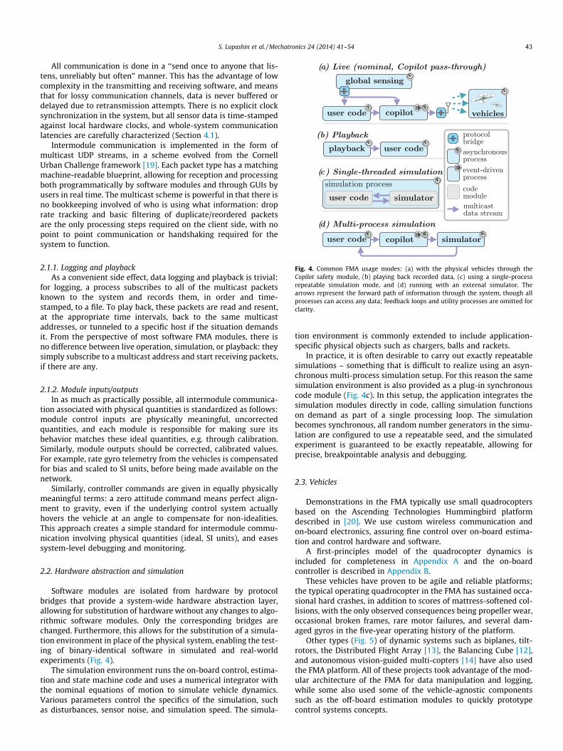
Fig. 4. Common FMA usage modes: (a) with the physical vehicles through theCopilot safety module, (b) playing back recorded data, (c) using a single-processrepeatable simulation mode, and (d) running with an external simulator. Thearrows represent the forward path of information through the system, though allprocesses can access any data; feedback loops and utility processes are omitted forclarity.
S. Lupashin et al. / Mechatronics 24 (2014) 41–54 43
All communication is done in a ‘‘send once to anyone that lis-tens, unreliably but often’’ manner. This has the advantage of lowcomplexity in the transmitting and receiving software, and meansthat for lossy communication channels, data is never buffered ordelayed due to retransmission attempts. There is no explicit clocksynchronization in the system, but all sensor data is time-stampedagainst local hardware clocks, and whole-system communicationlatencies are carefully characterized (Section 4.1).
Intermodule communication is implemented in the form ofmulticast UDP streams, in a scheme evolved from the CornellUrban Challenge framework [19]. Each packet type has a matchingmachine-readable blueprint, allowing for reception and processingboth programmatically by software modules and through GUIs byusers in real time. The multicast scheme is powerful in that there isno bookkeeping involved of who is using what information: droprate tracking and basic filtering of duplicate/reordered packetsare the only processing steps required on the client side, with nopoint to point communication or handshaking required for thesystem to function.
2.1.1. Logging and playbackAs a convenient side effect, data logging and playback is trivial:
for logging, a process subscribes to all of the multicast packetsknown to the system and records them, in order and time-stamped, to a file. To play back, these packets are read and resent,at the appropriate time intervals, back to the same multicastaddresses, or tunneled to a specific host if the situation demandsit. From the perspective of most software FMA modules, there isno difference between live operation, simulation, or playback: theysimply subscribe to a multicast address and start receiving packets,if there are any.
2.1.2. Module inputs/outputsIn as much as practically possible, all intermodule communica-
tion associated with physical quantities is standardized as follows:module control inputs are physically meaningful, uncorrectedquantities, and each module is responsible for making sure itsbehavior matches these ideal quantities, e.g. through calibration.Similarly, module outputs should be corrected, calibrated values.For example, rate gyro telemetry from the vehicles is compensatedfor bias and scaled to SI units, before being made available on thenetwork.
Similarly, controller commands are given in equally physicallymeaningful terms: a zero attitude command means perfect align-ment to gravity, even if the underlying control system actuallyhovers the vehicle at an angle to compensate for non-idealities.This approach creates a simple standard for intermodule commu-nication involving physical quantities (ideal, SI units), and easessystem-level debugging and monitoring.
2.2. Hardware abstraction and simulation
Software modules are isolated from hardware by protocolbridges that provide a system-wide hardware abstraction layer,allowing for substitution of hardware without any changes to algo-rithmic software modules. Only the corresponding bridges arechanged. Furthermore, this allows for the substitution of a simula-tion environment in place of the physical system, enabling the test-ing of binary-identical software in simulated and real-worldexperiments (Fig. 4).
The simulation environment runs the on-board control, estima-tion and state machine code and uses a numerical integrator withthe nominal equations of motion to simulate vehicle dynamics.Various parameters control the specifics of the simulation, suchas disturbances, sensor noise, and simulation speed. The simula-
tion environment is commonly extended to include application-specific physical objects such as chargers, balls and rackets.
In practice, it is often desirable to carry out exactly repeatablesimulations – something that is difficult to realize using an asyn-chronous multi-process simulation setup. For this reason the samesimulation environment is also provided as a plug-in synchronouscode module (Fig. 4c). In this setup, the application integrates thesimulation modules directly in code, calling simulation functionson demand as part of a single processing loop. The simulationbecomes synchronous, all random number generators in the simu-lation are configured to use a repeatable seed, and the simulatedexperiment is guaranteed to be exactly repeatable, allowing forprecise, breakpointable analysis and debugging.
2.3. Vehicles
Demonstrations in the FMA typically use small quadrocoptersbased on the Ascending Technologies Hummingbird platformdescribed in [20]. We use custom wireless communication andon-board electronics, assuring fine control over on-board estima-tion and control hardware and software.
A first-principles model of the quadrocopter dynamics isincluded for completeness in Appendix A and the on-boardcontroller is described in Appendix B.
These vehicles have proven to be agile and reliable platforms;the typical operating quadrocopter in the FMA has sustained occa-sional hard crashes, in addition to scores of mattress-softened col-lisions, with the only observed consequences being propeller wear,occasional broken frames, rare motor failures, and several dam-aged gyros in the five-year operating history of the platform.
Other types (Fig. 5) of dynamic systems such as biplanes, tilt-rotors, the Distributed Flight Array [13], the Balancing Cube [12],and autonomous vision-guided multi-copters [14] have also usedthe FMA platform. All of these projects took advantage of the mod-ular architecture of the FMA for data manipulation and logging,while some also used some of the vehicle-agnostic componentssuch as the off-board estimation modules to quickly prototypecontrol systems concepts.
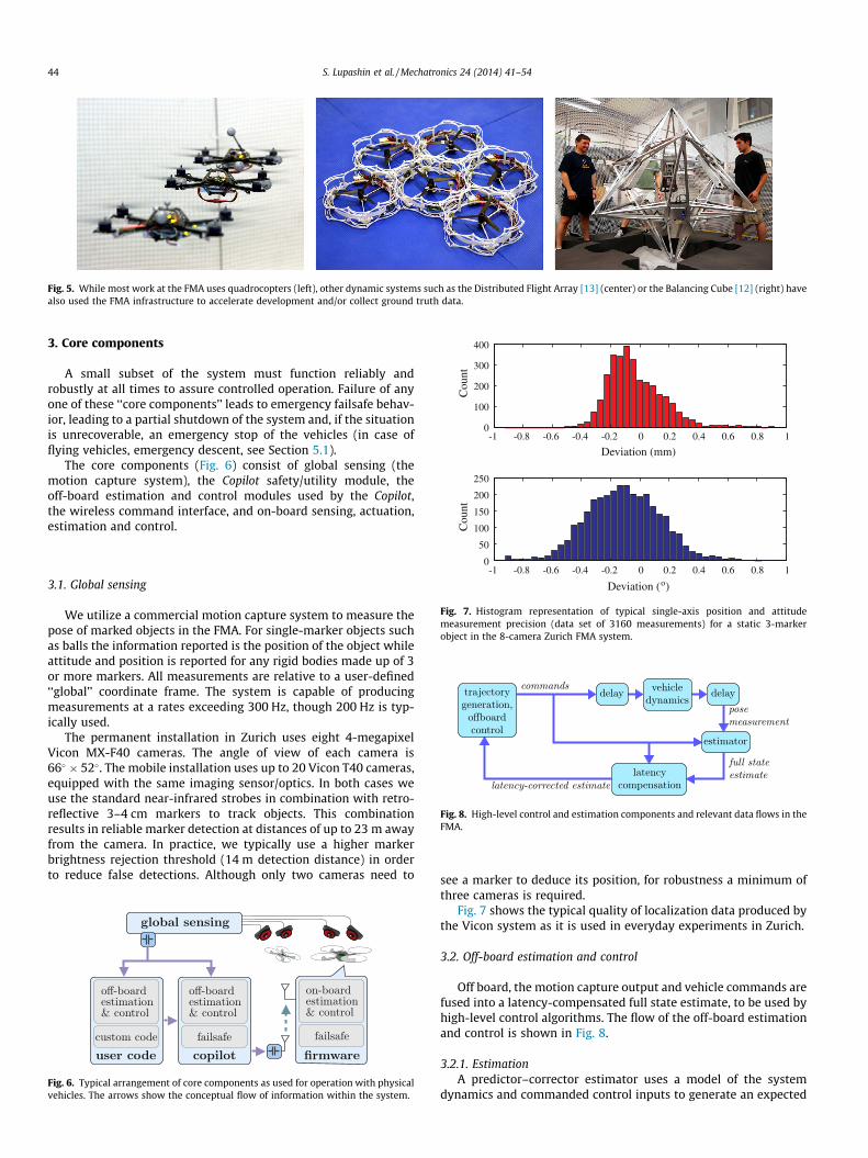
Fig. 5. While most work at the FMA uses quadrocopters (left), other dynamic systems such as the Distributed Flight Array [13] (center) or the Balancing Cube [12] (right) havealso used the FMA infrastructure to accelerate development and/or collect ground truth data.
-1 -0.8 -0.6 -0.4 -0.2 0 0.2 0.4 0.6 0.8 10
100
200
300
400
Deviation (mm)C
ount
100
150
200
250
Cou
nt
44 S. Lupashin et al. / Mechatronics 24 (2014) 41–54
3. Core components
A small subset of the system must function reliably androbustly at all times to assure controlled operation. Failure of anyone of these ‘‘core components’’ leads to emergency failsafe behav-ior, leading to a partial shutdown of the system and, if the situationis unrecoverable, an emergency stop of the vehicles (in case offlying vehicles, emergency descent, see Section 5.1).
The core components (Fig. 6) consist of global sensing (themotion capture system), the Copilot safety/utility module, theoff-board estimation and control modules used by the Copilot,the wireless command interface, and on-board sensing, actuation,estimation and control.
-1 -0.8 -0.6 -0.4 -0.2 0 0.2 0.4 0.6 0.8 10
50
Deviation (o)
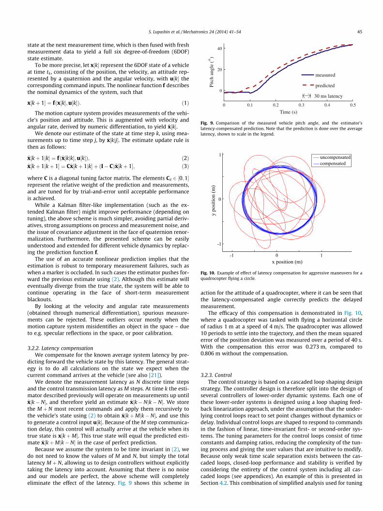
Fig. 7. Histogram representation of typical single-axis position and attitudemeasurement precision (data set of 3160 measurements) for a static 3-markerobject in the 8-camera Zurich FMA system.
Fig. 8. High-level control and estimation components and relevant data flows in theFMA.
3.1. Global sensing
We utilize a commercial motion capture system to measure thepose of marked objects in the FMA. For single-marker objects suchas balls the information reported is the position of the object whileattitude and position is reported for any rigid bodies made up of 3or more markers. All measurements are relative to a user-defined‘‘global’’ coordinate frame. The system is capable of producingmeasurements at a rates exceeding 300 Hz, though 200 Hz is typ-ically used.
The permanent installation in Zurich uses eight 4-megapixelVicon MX-F40 cameras. The angle of view of each camera is66� � 52�. The mobile installation uses up to 20 Vicon T40 cameras,equipped with the same imaging sensor/optics. In both cases weuse the standard near-infrared strobes in combination with retro-reflective 3–4 cm markers to track objects. This combinationresults in reliable marker detection at distances of up to 23 m awayfrom the camera. In practice, we typically use a higher markerbrightness rejection threshold (14 m detection distance) in orderto reduce false detections. Although only two cameras need to
Fig. 6. Typical arrangement of core components as used for operation with physicalvehicles. The arrows show the conceptual flow of information within the system.
see a marker to deduce its position, for robustness a minimum ofthree cameras is required.
Fig. 7 shows the typical quality of localization data produced bythe Vicon system as it is used in everyday experiments in Zurich.
3.2. Off-board estimation and control
Off board, the motion capture output and vehicle commands arefused into a latency-compensated full state estimate, to be used byhigh-level control algorithms. The flow of the off-board estimationand control is shown in Fig. 8.
3.2.1. EstimationA predictor–corrector estimator uses a model of the system
dynamics and commanded control inputs to generate an expected
0 0.1 0.2 0.3 0.4 0.5
0
20
40
Time (s)
Pitc
h an
gle
(o)
measured
predicted
30 ms latency
Fig. 9. Comparison of the measured vehicle pitch angle, and the estimator’slatency-compensated prediction. Note that the prediction is done over the averagelatency, shown to scale in the legend.
Fig. 10. Example of effect of latency compensation for aggressive maneuvers for aquadrocopter flying a circle.
S. Lupashin et al. / Mechatronics 24 (2014) 41–54 45
state at the next measurement time, which is then fused with freshmeasurement data to yield a full six degree-of-freedom (6DOF)state estimate.
To be more precise, let x½k� represent the 6DOF state of a vehicleat time tk, consisting of the position, the velocity, an attitude rep-resented by a quaternion and the angular velocity, with u½k� thecorresponding command inputs. The nonlinear function f describesthe nominal dynamics of the system, such that
x½kþ 1� ¼ fðx½k�;u½k�Þ: ð1Þ
The motion capture system provides measurements of the vehi-cle’s position and attitude. This is augmented with velocity andangular rate, derived by numeric differentiation, to yield ~x½k�.
We denote our estimate of the state at time step k, using mea-surements up to time step j, by x̂½kjj�. The estimate update rule isthen as follows:
x̂½kþ 1jk� ¼ fðx̂½kjk�;u½k�Þ; ð2Þx̂½kþ 1jkþ 1� ¼ Cx̂½kþ 1jk� þ ðI� CÞ~x½kþ 1�; ð3Þ
where C is a diagonal tuning factor matrix. The elements Cii 2 ½0;1�represent the relative weight of the prediction and measurements,and are tuned for by trial-and-error until acceptable performanceis achieved.
While a Kalman filter-like implementation (such as the ex-tended Kalman filter) might improve performance (depending ontuning), the above scheme is much simpler, avoiding partial deriv-atives, strong assumptions on process and measurement noise, andthe issue of covariance adjustment in the face of quaternion renor-malization. Furthermore, the presented scheme can be easilyunderstood and extended for different vehicle dynamics by replac-ing the prediction function f.
The use of an accurate nonlinear prediction implies that theestimation is robust to temporary measurement failures, such aswhen a marker is occluded. In such cases the estimator pushes for-ward the previous estimate using (2). Although this estimate willeventually diverge from the true state, the system will be able tocontinue operating in the face of short-term measurementblackouts.
By looking at the velocity and angular rate measurements(obtained through numerical differentiation), spurious measure-ments can be rejected. These outliers occur mostly when themotion capture system misidentifies an object in the space – dueto e.g. specular reflections in the space, or poor calibration.
3.2.2. Latency compensationWe compensate for the known average system latency by pre-
dicting forward the vehicle state by this latency. The general strat-egy is to do all calculations on the state we expect when thecurrent command arrives at the vehicle (see also [21]).
We denote the measurement latency as N discrete time stepsand the control transmission latency as M steps. At time k the esti-mator described previously will operate on measurements up until~x½k� N�, and therefore yield an estimate x̂½k� Njk� N�. We storethe M þ N most recent commands and apply them recursively tothe vehicle’s state using (2) to obtain x̂½kþMjk� N�, and use thisto generate a control input u½k�. Because of the M step communica-tion delay, this control will actually arrive at the vehicle when itstrue state is x½kþM�. This true state will equal the predicted esti-mate x̂½kþMjk� N� in the case of perfect prediction.
Because we assume the system to be time invariant in (2), wedo not need to know the values of M and N, but simply the totallatency M þ N, allowing us to design controllers without explicitlytaking the latency into account. Assuming that there is no noiseand our models are perfect, the above scheme will completelyeliminate the effect of the latency. Fig. 9 shows this scheme in
action for the attitude of a quadrocopter, where it can be seen thatthe latency-compensated angle correctly predicts the delayedmeasurement.
The efficacy of this compensation is demonstrated in Fig. 10,where a quadrocopter was tasked with flying a horizontal circleof radius 1 m at a speed of 4 m/s. The quadrocopter was allowed10 periods to settle into the trajectory, and then the mean squarederror of the position deviation was measured over a period of 40 s.With the compensation this error was 0.273 m, compared to0.806 m without the compensation.
3.2.3. ControlThe control strategy is based on a cascaded loop shaping design
strategy. The controller design is therefore split into the design ofseveral controllers of lower-order dynamic systems. Each one ofthese lower-order systems is designed using a loop shaping feed-back linearization approach, under the assumption that the under-lying control loops react to set point changes without dynamics ordelay. Individual control loops are shaped to respond to commandsin the fashion of linear, time-invariant first- or second-order sys-tems. The tuning parameters for the control loops consist of timeconstants and damping ratios, reducing the complexity of the tun-ing process and giving the user values that are intuitive to modify.Because only weak time scale separation exists between the cas-caded loops, closed-loop performance and stability is verified byconsidering the entirety of the control system including all cas-caded loops (see appendices). An example of this is presented inSection 4.2. This combination of simplified analysis used for tuning
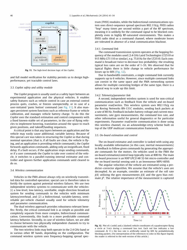
Fig. 11. The high-level decision logic of the Copilot.
8 9 10 11 12 13 14 15
-0.5
0
0.5
Time (s)
Posi
tion
(m)
Fig. 12. Plot of x (solid) and y (dashed) vehicle coordinates of a quadrocopter flyinga circle at 3 m/s during a command loss test. Each red line indicates a lostcommand. At 11 s the loss rate is artificially raised by 60% by probabilisticallyblocking packets. (For interpretation of the references to color in this figure legend,the reader is referred to the web version of this article.)
46 S. Lupashin et al. / Mechatronics 24 (2014) 41–54
and full model verification for stability permits us to design high-performance, yet tractable control laws.
3.3. Copilot safety and utility module
The Copilot program is usually used as a safety layer between anexperimental application and the physical vehicles. It enablessafety features such as vehicle control in case an external controlprocess quits, crashes, or freezes unexpectedly, or in case of auser-initiated ‘panic button’ command (see Fig. 11). It also man-ages persistent system functions such as reference frame or vehiclecalibration, and manages vehicle battery charge. To do this theCopilot uses the standard estimation and control components witha fixed known-stable set of parameters, in the case of flying vehi-cles to implement hovering, translation around the space to reachgiven positions, and takeoff/landing sequences.
A critical point is that any layers between an application and thevehicle may easily cause additional, variable latency. Because ofthis special care was taken in structuring the Copilot so that duringnominal operation (that is, if all faults are clear, the vehicle is fly-ing, and an application is providing vehicle commands), the Copilotforwards application commands, adding only an insignificant, fixeddelay. If a fault occurs, if the application stops sending commands,or if a user commands the Copilot to take over control of the vehi-cle, it switches to a parallel-running internal estimator and con-troller and ignores further application commands until cleared todo so.
3.4. Wireless communication
Vehicles in the FMA almost always rely on wirelessly transmit-ted data for controlled operation; special care is therefore taken tofortify the system against potential wireless failures. We use twoindependent wireless systems to communicate with the vehicles:(i) a low-level, low-latency, unreliable, single-direction broadcastsystem for sending commands to the vehicles with minimumlatency/overhead, and (2) a bidirectional, variable-latency, semi-reliable per-vehicle channel usually used for vehicle telemetryand parameter communication.
The dual wireless approach provides robustness-relevant bene-fits: firstly, the critical command link is as simple as possible andcompletely separate from more complex, bidirectional communi-cation. Conveniently, this leads to a more predictable commandlatency behavior. Secondly, in case of wireless failure, we are ableto choose between two physically independent channels to try tocommunicate with the vehicle.
The two wireless links may both operate in the 2.4 GHz band orin various other RF bands, depending on the configuration. Thecommand wireless system uses frequency-hopping spread spec-
trum (FHSS) modules, while the bidirectional communications sys-tem uses direct-sequence spread spectrum 802.11b/g. FHSS radios‘‘hop’’ many times per second within a part of the RF spectrum,meaning it is unlikely for the command signal to be blocked com-pletely even in highly RF-saturated environments. This makes aFHSS radio ideal as a command channel, where moderate lossesare tolerated in absence of a total communication blackout.
3.4.1. Command linkThe command transmission system operates at the hopping fre-
quency of the modules used (2.4 GHz Laird Technologies LT2510 or915 MHz LT1110 or similar), e.g. 75.8 Hz for the LT2510. Each com-mand is broadcast twice to decrease loss probability; the resultingtypical loss rates are on the order of 1–5%. We observed that fortypical flights there is little change to vehicle performance forlosses up to 60% (Fig. 12).
Due to bandwidth constraints, a single command link currentlysupports up to 6 vehicles. However, since multiple command linkscan coexist in the same space and the FMA networking systemallows for multiple coexisting bridges of the same type, there is anatural way to scale up this limit.
3.4.2. Telemetry/parameter linkA second, independent wireless system is used for non-critical
communication such as feedback from the vehicle and on-boardparameter read/writes. This wireless system uses 802.11b/g viathe Roving Networks RN-131C modules, sending back packets ata rate of 80 Hz. Feedback includes battery voltage and current mea-surements, rate gyro measurements, the command loss rate, andother information useful for general diagnostics or for particularexperiments. Parameter read/write communication is done usingthis wireless channel, via an acknowledge-retry scheme built ontop of the UDP multicast communication framework.
3.5. On-board estimation and control
The on-board estimator and controller is tasked with using anylocally available information (in this case, inertial measurements)in feedback to follow given commands by generating the appropri-ate commands for the motors. On vehicles used in the FMA theon-board estimation/control loop typically runs at 800 Hz. The mainon-board processor is an NXP LPC2148 32-bit micro-controller andthe on-board inertial sensing unit is an Invensense MPU-6050.
The angular velocities of the vehicle are estimated using a pre-dictor–corrector algorithm. We assume that the vehicle’s axes aredecoupled. As an example, consider an estimate of the roll ratep̂½k� utilizing the gyro measurements ~p½k� and the gyro bias esti-mate p̂0. The relative importance of the measurement is captured
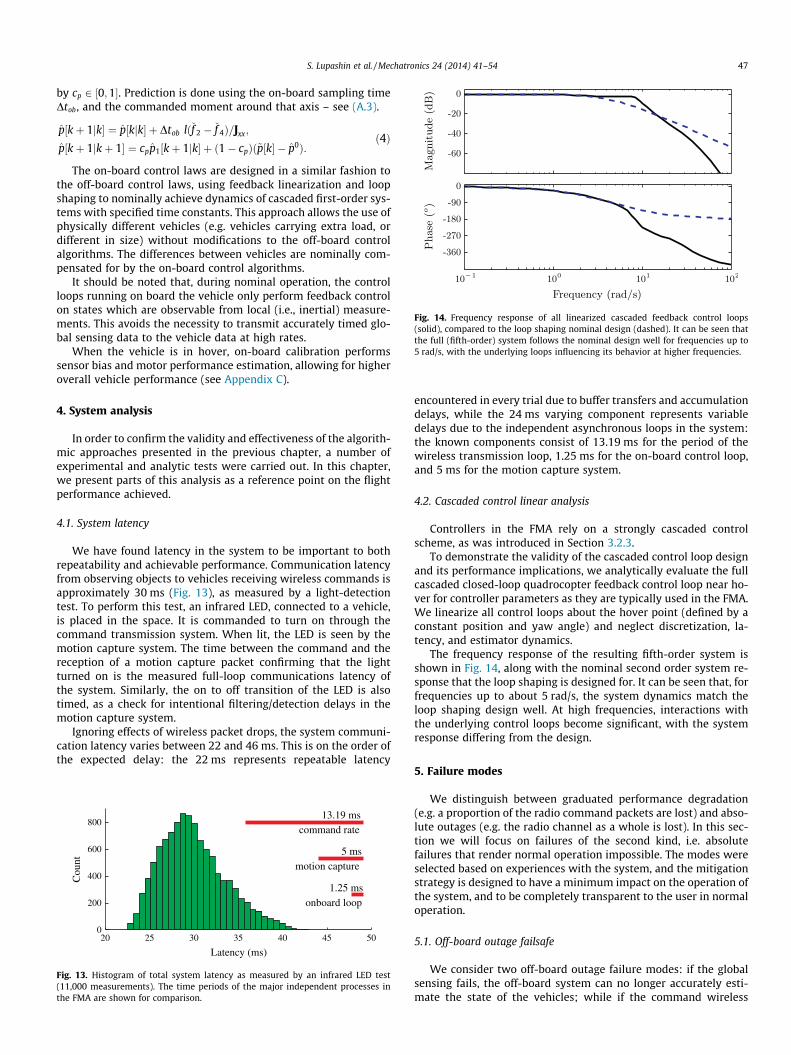
Fig. 14. Frequency response of all linearized cascaded feedback control loops(solid), compared to the loop shaping nominal design (dashed). It can be seen thatthe full (fifth-order) system follows the nominal design well for frequencies up to5 rad/s, with the underlying loops influencing its behavior at higher frequencies.
S. Lupashin et al. / Mechatronics 24 (2014) 41–54 47
by cp 2 ½0;1�. Prediction is done using the on-board sampling timeDtob, and the commanded moment around that axis – see (A.3).
p̂½kþ 1jk� ¼ p̂½kjk� þ Dtob lð�f 2 � �f 4Þ=Jxx;
p̂½kþ 1jkþ 1� ¼ cpp̂1½kþ 1jk� þ ð1� cpÞð~p½k� � p̂0Þ:ð4Þ
The on-board control laws are designed in a similar fashion tothe off-board control laws, using feedback linearization and loopshaping to nominally achieve dynamics of cascaded first-order sys-tems with specified time constants. This approach allows the use ofphysically different vehicles (e.g. vehicles carrying extra load, ordifferent in size) without modifications to the off-board controlalgorithms. The differences between vehicles are nominally com-pensated for by the on-board control algorithms.
It should be noted that, during nominal operation, the controlloops running on board the vehicle only perform feedback controlon states which are observable from local (i.e., inertial) measure-ments. This avoids the necessity to transmit accurately timed glo-bal sensing data to the vehicle data at high rates.
When the vehicle is in hover, on-board calibration performssensor bias and motor performance estimation, allowing for higheroverall vehicle performance (see Appendix C).
4. System analysis
In order to confirm the validity and effectiveness of the algorith-mic approaches presented in the previous chapter, a number ofexperimental and analytic tests were carried out. In this chapter,we present parts of this analysis as a reference point on the flightperformance achieved.
4.1. System latency
We have found latency in the system to be important to bothrepeatability and achievable performance. Communication latencyfrom observing objects to vehicles receiving wireless commands isapproximately 30 ms (Fig. 13), as measured by a light-detectiontest. To perform this test, an infrared LED, connected to a vehicle,is placed in the space. It is commanded to turn on through thecommand transmission system. When lit, the LED is seen by themotion capture system. The time between the command and thereception of a motion capture packet confirming that the lightturned on is the measured full-loop communications latency ofthe system. Similarly, the on to off transition of the LED is alsotimed, as a check for intentional filtering/detection delays in themotion capture system.
Ignoring effects of wireless packet drops, the system communi-cation latency varies between 22 and 46 ms. This is on the order ofthe expected delay: the 22 ms represents repeatable latency
20 25 30 35 40 45 500
200
400
600
800command rate
13.19 ms
motion capture5 ms
onboard loop1.25 ms
Latency (ms)
Cou
nt
Fig. 13. Histogram of total system latency as measured by an infrared LED test(11,000 measurements). The time periods of the major independent processes inthe FMA are shown for comparison.
encountered in every trial due to buffer transfers and accumulationdelays, while the 24 ms varying component represents variabledelays due to the independent asynchronous loops in the system:the known components consist of 13.19 ms for the period of thewireless transmission loop, 1.25 ms for the on-board control loop,and 5 ms for the motion capture system.
4.2. Cascaded control linear analysis
Controllers in the FMA rely on a strongly cascaded controlscheme, as was introduced in Section 3.2.3.
To demonstrate the validity of the cascaded control loop designand its performance implications, we analytically evaluate the fullcascaded closed-loop quadrocopter feedback control loop near ho-ver for controller parameters as they are typically used in the FMA.We linearize all control loops about the hover point (defined by aconstant position and yaw angle) and neglect discretization, la-tency, and estimator dynamics.
The frequency response of the resulting fifth-order system isshown in Fig. 14, along with the nominal second order system re-sponse that the loop shaping is designed for. It can be seen that, forfrequencies up to about 5 rad/s, the system dynamics match theloop shaping design well. At high frequencies, interactions withthe underlying control loops become significant, with the systemresponse differing from the design.
5. Failure modes
We distinguish between graduated performance degradation(e.g. a proportion of the radio command packets are lost) and abso-lute outages (e.g. the radio channel as a whole is lost). In this sec-tion we will focus on failures of the second kind, i.e. absolutefailures that render normal operation impossible. The modes wereselected based on experiences with the system, and the mitigationstrategy is designed to have a minimum impact on the operation ofthe system, and to be completely transparent to the user in normaloperation.
5.1. Off-board outage failsafe
We consider two off-board outage failure modes: if the globalsensing fails, the off-board system can no longer accurately esti-mate the state of the vehicles; while if the command wireless
48 S. Lupashin et al. / Mechatronics 24 (2014) 41–54
channel fails, the off-board system can no longer command thevehicle. Because ‘‘do nothing and wait’’ is not a valid action for aflying vehicle (as opposed to e.g. a ground vehicle), an on-boardemergency control was developed for the quadrocopters in theFMA, to mitigate the danger of an off-board outage [22]. The goalis to safely bring the quadrocopters to a standstill when there isno external data to rely on.
This is done by periodically sending to the quadrocopter thecurrent off board state estimate over the bidirectional communica-tion link. These state estimates are then pushed forward with mea-surements from the on-board rate gyroscopes (Eq. (4)), which areintegrated to yield open-loop estimates for the vehicle attitudeand velocity (Eq. (A.1)). Because we are integrating a noisy, biasedsignal, the angle and speed estimates will only be valid for shortperiods of time.
A prerequisite for entering emergency on-board control is thatthe on-board estimates for the quadrocopter’s angles and lateralspeeds are reasonable (not too large), and that these estimateshave been recently updated with external data. If the estimates failthis test, the quadrocopter immediately switches off all propellers,the idea being that the worst case scenario when taking no actionis better than that for executing an unpredictable action.
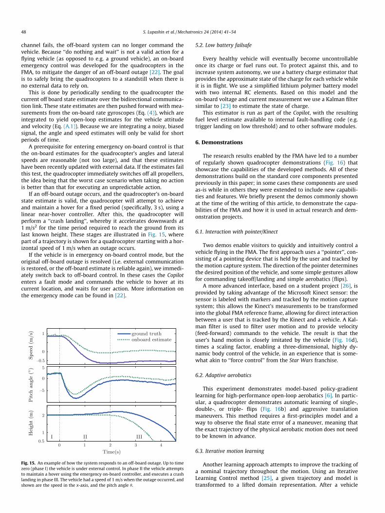
If an off-board outage occurs, and the quadrocopter’s on-boardstate estimate is valid, the quadrocopter will attempt to achieveand maintain a hover for a fixed period (specifically, 3 s), using alinear near-hover controller. After this, the quadrocopter willperform a ‘‘crash landing’’, whereby it accelerates downwards at1 m/s2 for the time period required to reach the ground from itslast known height. These stages are illustrated in Fig. 15, wherepart of a trajectory is shown for a quadrocopter starting with a hor-izontal speed of 1 m/s when an outage occurs.
If the vehicle is in emergency on-board control mode, but theoriginal off-board outage is resolved (i.e. external communicationis restored, or the off-board estimate is reliable again), we immedi-ately switch back to off-board control. In these cases the Copilotenters a fault mode and commands the vehicle to hover at itscurrent location, and waits for user action. More information onthe emergency mode can be found in [22].
Fig. 15. An example of how the system responds to an off-board outage. Up to timezero (phase I) the vehicle is under external control. In phase II the vehicle attemptsto maintain a hover using the emergency on-board controller, and executes a crashlanding in phase III. The vehicle had a speed of 1 m/s when the outage occurred, andshown are the speed in the x-axis, and the pitch angle h.
5.2. Low battery failsafe
Every healthy vehicle will eventually become uncontrollableonce its charge or fuel runs out. To protect against this, and toincrease system autonomy, we use a battery charge estimator thatprovides the approximate state of the charge for each vehicle whileit is in flight. We use a simplified lithium polymer battery modelwith two internal RC elements. Based on this model and theon-board voltage and current measurement we use a Kalman filtersimilar to [23] to estimate the state of charge.
This estimator is run as part of the Copilot, with the resultingfuel level estimate available to internal fault-handling code (e.g.trigger landing on low threshold) and to other software modules.
6. Demonstrations
The research results enabled by the FMA have led to a numberof regularly shown quadrocopter demonstrations (Fig. 16) thatshowcase the capabilities of the developed methods. All of thesedemonstrations build on the standard core components presentedpreviously in this paper; in some cases these components are usedas-is while in others they were extended to include new capabili-ties and features. We briefly present the demos commonly shownat the time of the writing of this article, to demonstrate the capa-bilities of the FMA and how it is used in actual research and dem-onstration projects.
6.1. Interaction with pointer/Kinect
Two demos enable visitors to quickly and intuitively control avehicle flying in the FMA. The first approach uses a ‘‘pointer’’, con-sisting of a pointing device that is held by the user and tracked bythe motion capture system. The direction of the pointer determinesthe desired position of the vehicle, and some simple gestures allowfor commanding takeoff/landing and simple aerobatics (flips).
A more advanced interface, based on a student project [26], isprovided by taking advantage of the Microsoft Kinect sensor: thesensor is labeled with markers and tracked by the motion capturesystem; this allows the Kinect’s measurements to be transformedinto the global FMA reference frame, allowing for direct interactionbetween a user that is tracked by the Kinect and a vehicle. A Kal-man filter is used to filter user motion and to provide velocity(feed-forward) commands to the vehicle. The result is that theuser’s hand motion is closely imitated by the vehicle (Fig. 16d),times a scaling factor, enabling a three-dimensional, highly dy-namic body control of the vehicle, in an experience that is some-what akin to ‘‘force control’’ from the Star Wars franchise.
6.2. Adaptive aerobatics
This experiment demonstrates model-based policy-gradientlearning for high-performance open-loop aerobatics [6]. In partic-ular, a quadrocopter demonstrates automatic learning of single-,double-, or triple- flips (Fig. 16b) and aggressive translationmaneuvers. This method requires a first-principles model and away to observe the final state error of a maneuver, meaning thatthe exact trajectory of the physical aerobatic motion does not needto be known in advance.
6.3. Iterative motion learning
Another learning approach attempts to improve the tracking ofa nominal trajectory throughout the motion. Using an IterativeLearning Control method [25], a given trajectory and model istransformed to a lifted domain representation. After a vehicle
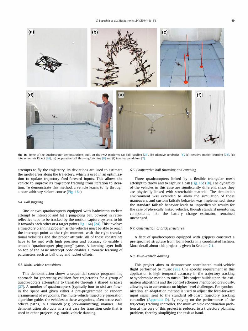
Fig. 16. Some of the quadrocopter demonstrations built on the FMA platform: (a) ball juggling [24], (b) adaptive acrobatics [6], (c) iterative motion learning [25], (d)interaction via Kinect [26], (e) cooperative ball throwing/catching [8] and (f) inverted pendulum [7].
S. Lupashin et al. / Mechatronics 24 (2014) 41–54 49
attempts to fly the trajectory, its deviations are used to estimatethe model error along the trajectory, which is used in an optimiza-tion to update trajectory feed-forward inputs. This allows thevehicle to improve its trajectory tracking from iteration to itera-tion. To demonstrate this method, a vehicle learns to fly througha near-arbitrary slalom course (Fig. 16c).
6.4. Ball juggling
One or two quadrocopters equipped with badminton racketsattempt to intercept and hit a ping-pong ball, covered in retro-reflective tape to be tracked by the motion capture system, to hitit towards each other or a target point (Fig. 16a) [24]. This involvesa trajectory planning problem as the vehicles must be able to reachthe intercept point at the right moment, with the right transla-tional velocities and the proper attitude. All of these constraintshave to be met with high precision and accuracy to enable asmooth ‘‘quadrocopter ping-pong’’ game. A learning layer builton top of the basic intercept code enables automatic learning ofparameters such as ball drag and racket offsets.
6.5. Multi-vehicle transitions
This demonstration shows a sequential convex programmingapproach for generating collision-free trajectories for a group ofquadrocopters attempting to translate through a shared airspace[27]. A number of quadrocopters (typically four to six) are flownin the space and given either a pre-programmed or randomarrangement of waypoints. The multi-vehicle trajectory generationalgorithm guides the vehicles to these waypoints, often across eachother’s paths, in a smooth (e.g. jerk-minimizing) manner. Thisdemonstration also acts as a test case for transition code that isused in other projects, e.g. multi-vehicle dancing.
6.6. Cooperative ball throwing and catching
Three quadrocopters linked by a flexible triangular meshattempt to throw and to capture a ball (Fig. 16e) [8]. The dynamicsof the vehicles in this case are significantly different, since theyare physically linked with stretchable material. The simulationenvironment was extended to allow the simulation of thesemaneuvers, and custom failsafe behavior was implemented, sincethe standard failsafe behavior leads to unpredictable results forthe case of physically linked vehicles, though standard monitoringcomponents, like the battery charge estimator, remainedunchanged.
6.7. Construction of brick structures
A fleet of quadrocopters equipped with grippers construct apre-specified structure from foam bricks in a coordinated fashion.More detail about this project is given in Section 7.1.
6.8. Multi-vehicle dancing
This project aims to demonstrate coordinated multi-vehicleflight performed to music [28]. One specific requirement in thisapplication is high temporal accuracy in the trajectory trackingto synchronize motion to music. This project builds upon the esti-mation algorithms and the control schemes mentioned previously,allowing us to concentrate on higher-level challenges. For synchro-nization, an adaptation method is used to adjust the feed-forwardinput signal sent to the standard off-board trajectory trackingcontroller (Appendix D). By relying on the performance of thetrajectory tracking controller, the multi-vehicle coordination prob-lem at the core of this project is reduced to a trajectory planningproblem, thereby simplifying the task at hand.
50 S. Lupashin et al. / Mechatronics 24 (2014) 41–54
6.9. Flying inverted pendulum
This project aims to balance an inverted pendulum on a quadro-copter (Fig. 16f) [7]. Internally, it is implemented as a task-specificestimator and controller that interacts with the standard simulatorand the communication infrastructure. In simulation, the vehicledynamics are extended to include the equations of motion forthe inverted pendulum. The balancing task has more recently beenextended to allow a first vehicle to maneuver such that the pendu-lum is thrown in the air for a second vehicle to catch it and to bal-ance it again [29].
6.10. Physical human–quadrocopter interaction
The application of admittance control to quadrocopters is dem-onstrated in this project [30]. The admittance controller allows auser to define the apparent inertia, damping, and stiffness of therobot, and interact with it by physically guiding it. The project usesa custom estimator to include the estimation of external forces act-ing on the vehicle, and leverages the standard trajectory trackingcontroller by adjusting the reference trajectory applied to it suchthat the desired admittance properties are achieved.
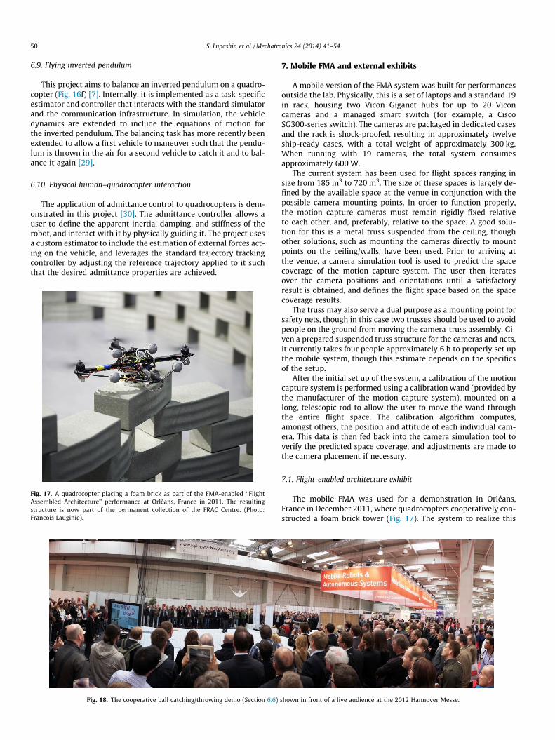
Fig. 17. A quadrocopter placing a foam brick as part of the FMA-enabled ‘‘FlightAssembled Architecture’’ performance at Orléans, France in 2011. The resultingstructure is now part of the permanent collection of the FRAC Centre. (Photo:Francois Lauginie).
Fig. 18. The cooperative ball catching/throwing demo (Section 6.6)
7. Mobile FMA and external exhibits
A mobile version of the FMA system was built for performancesoutside the lab. Physically, this is a set of laptops and a standard 19in rack, housing two Vicon Giganet hubs for up to 20 Viconcameras and a managed smart switch (for example, a CiscoSG300-series switch). The cameras are packaged in dedicated casesand the rack is shock-proofed, resulting in approximately twelveship-ready cases, with a total weight of approximately 300 kg.When running with 19 cameras, the total system consumesapproximately 600 W.
The current system has been used for flight spaces ranging insize from 185 m3 to 720 m3. The size of these spaces is largely de-fined by the available space at the venue in conjunction with thepossible camera mounting points. In order to function properly,the motion capture cameras must remain rigidly fixed relativeto each other, and, preferably, relative to the space. A good solu-tion for this is a metal truss suspended from the ceiling, thoughother solutions, such as mounting the cameras directly to mountpoints on the ceiling/walls, have been used. Prior to arriving atthe venue, a camera simulation tool is used to predict the spacecoverage of the motion capture system. The user then iteratesover the camera positions and orientations until a satisfactoryresult is obtained, and defines the flight space based on the spacecoverage results.
The truss may also serve a dual purpose as a mounting point forsafety nets, though in this case two trusses should be used to avoidpeople on the ground from moving the camera-truss assembly. Gi-ven a prepared suspended truss structure for the cameras and nets,it currently takes four people approximately 6 h to properly set upthe mobile system, though this estimate depends on the specificsof the setup.
After the initial set up of the system, a calibration of the motioncapture system is performed using a calibration wand (provided bythe manufacturer of the motion capture system), mounted on along, telescopic rod to allow the user to move the wand throughthe entire flight space. The calibration algorithm computes,amongst others, the position and attitude of each individual cam-era. This data is then fed back into the camera simulation tool toverify the predicted space coverage, and adjustments are made tothe camera placement if necessary.
7.1. Flight-enabled architecture exhibit
The mobile FMA was used for a demonstration in Orléans,France in December 2011, where quadrocopters cooperatively con-structed a foam brick tower (Fig. 17). The system to realize this
shown in front of a live audience at the 2012 Hannover Messe.
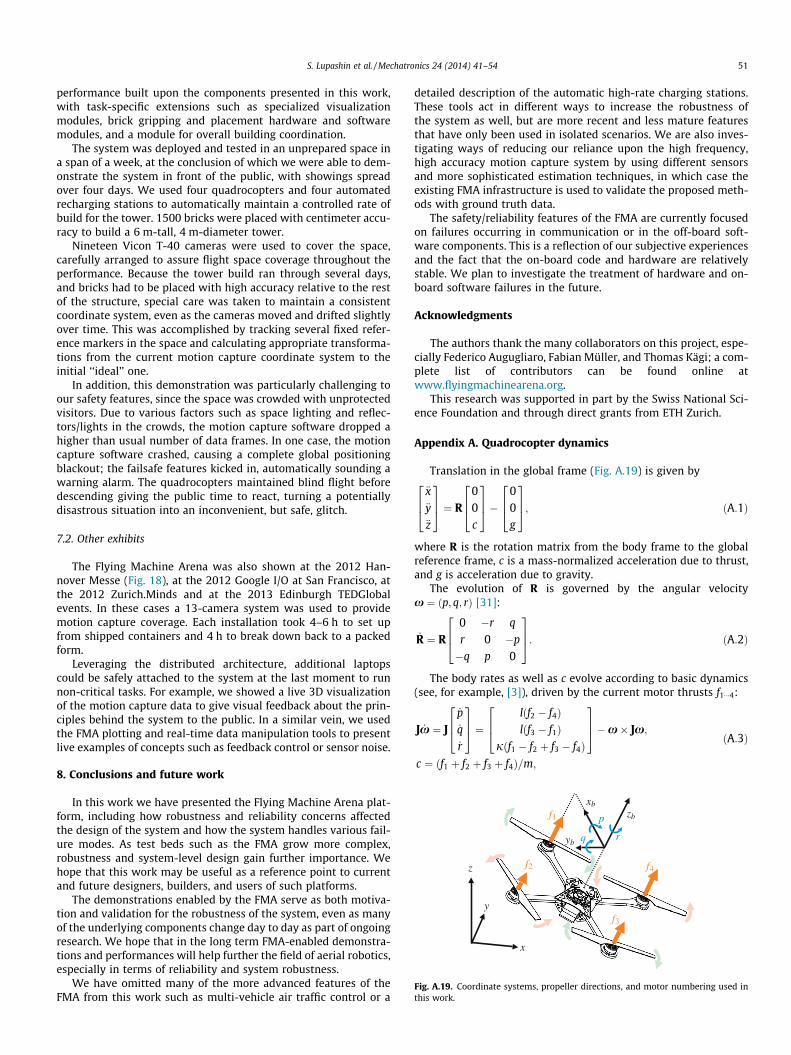
Fig. A.19. Coordinate systems, propeller directions, and motor numbering used inthis work.
S. Lupashin et al. / Mechatronics 24 (2014) 41–54 51
performance built upon the components presented in this work,with task-specific extensions such as specialized visualizationmodules, brick gripping and placement hardware and softwaremodules, and a module for overall building coordination.
The system was deployed and tested in an unprepared space ina span of a week, at the conclusion of which we were able to dem-onstrate the system in front of the public, with showings spreadover four days. We used four quadrocopters and four automatedrecharging stations to automatically maintain a controlled rate ofbuild for the tower. 1500 bricks were placed with centimeter accu-racy to build a 6 m-tall, 4 m-diameter tower.
Nineteen Vicon T-40 cameras were used to cover the space,carefully arranged to assure flight space coverage throughout theperformance. Because the tower build ran through several days,and bricks had to be placed with high accuracy relative to the restof the structure, special care was taken to maintain a consistentcoordinate system, even as the cameras moved and drifted slightlyover time. This was accomplished by tracking several fixed refer-ence markers in the space and calculating appropriate transforma-tions from the current motion capture coordinate system to theinitial ‘‘ideal’’ one.
In addition, this demonstration was particularly challenging toour safety features, since the space was crowded with unprotectedvisitors. Due to various factors such as space lighting and reflec-tors/lights in the crowds, the motion capture software dropped ahigher than usual number of data frames. In one case, the motioncapture software crashed, causing a complete global positioningblackout; the failsafe features kicked in, automatically sounding awarning alarm. The quadrocopters maintained blind flight beforedescending giving the public time to react, turning a potentiallydisastrous situation into an inconvenient, but safe, glitch.
7.2. Other exhibits
The Flying Machine Arena was also shown at the 2012 Han-nover Messe (Fig. 18), at the 2012 Google I/O at San Francisco, atthe 2012 Zurich.Minds and at the 2013 Edinburgh TEDGlobalevents. In these cases a 13-camera system was used to providemotion capture coverage. Each installation took 4–6 h to set upfrom shipped containers and 4 h to break down back to a packedform.
Leveraging the distributed architecture, additional laptopscould be safely attached to the system at the last moment to runnon-critical tasks. For example, we showed a live 3D visualizationof the motion capture data to give visual feedback about the prin-ciples behind the system to the public. In a similar vein, we usedthe FMA plotting and real-time data manipulation tools to presentlive examples of concepts such as feedback control or sensor noise.
8. Conclusions and future work
In this work we have presented the Flying Machine Arena plat-form, including how robustness and reliability concerns affectedthe design of the system and how the system handles various fail-ure modes. As test beds such as the FMA grow more complex,robustness and system-level design gain further importance. Wehope that this work may be useful as a reference point to currentand future designers, builders, and users of such platforms.
The demonstrations enabled by the FMA serve as both motiva-tion and validation for the robustness of the system, even as manyof the underlying components change day to day as part of ongoingresearch. We hope that in the long term FMA-enabled demonstra-tions and performances will help further the field of aerial robotics,especially in terms of reliability and system robustness.
We have omitted many of the more advanced features of theFMA from this work such as multi-vehicle air traffic control or a
detailed description of the automatic high-rate charging stations.These tools act in different ways to increase the robustness ofthe system as well, but are more recent and less mature featuresthat have only been used in isolated scenarios. We are also inves-tigating ways of reducing our reliance upon the high frequency,high accuracy motion capture system by using different sensorsand more sophisticated estimation techniques, in which case theexisting FMA infrastructure is used to validate the proposed meth-ods with ground truth data.
The safety/reliability features of the FMA are currently focusedon failures occurring in communication or in the off-board soft-ware components. This is a reflection of our subjective experiencesand the fact that the on-board code and hardware are relativelystable. We plan to investigate the treatment of hardware and on-board software failures in the future.
Acknowledgments
The authors thank the many collaborators on this project, espe-cially Federico Augugliaro, Fabian Müller, and Thomas Kägi; a com-plete list of contributors can be found online atwww.flyingmachinearena.org.
This research was supported in part by the Swiss National Sci-ence Foundation and through direct grants from ETH Zurich.
Appendix A. Quadrocopter dynamics
Translation in the global frame (Fig. A.19) is given by
€x€y€z
264375 ¼ R
00c
264375�
00g
264375; ðA:1Þ
where R is the rotation matrix from the body frame to the globalreference frame, c is a mass-normalized acceleration due to thrust,and g is acceleration due to gravity.
The evolution of R is governed by the angular velocityx ¼ ðp; q; rÞ [31]:
_R ¼ R0 �r q
r 0 �p
�q p 0
264
375: ðA:2Þ
The body rates as well as c evolve according to basic dynamics(see, for example, [3]), driven by the current motor thrusts f1���4:
J _x ¼ J
_p_q_r
264375 ¼
lðf2 � f4Þlðf3 � f1Þ
jðf1 � f2 þ f3 � f4Þ
264
375�x� Jx;
c ¼ ðf1 þ f2 þ f3 þ f4Þ=m;
ðA:3Þ
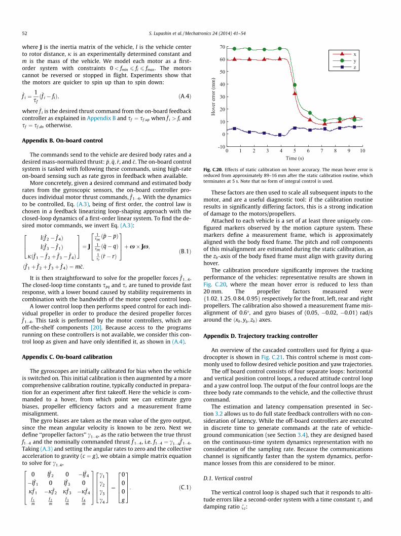
Fig. C.20. Effects of static calibration on hover accuracy. The mean hover error isreduced from approximately 89–16 mm after the static calibration routine, whichterminates at 5 s. Note that no form of integral control is used.
52 S. Lupashin et al. / Mechatronics 24 (2014) 41–54
where J is the inertia matrix of the vehicle, l is the vehicle centerto rotor distance, j is an experimentally determined constant andm is the mass of the vehicle. We model each motor as a first-order system with constraints 0 < fmin 6 fi 6 fmax. The motorscannot be reversed or stopped in flight. Experiments show thatthe motors are quicker to spin up than to spin down:
_f i ¼1sfð�f i � fiÞ; ðA:4Þ
where �f i is the desired thrust command from the on-board feedbackcontroller as explained in Appendix B and sf ¼ sf ;up when �f i > fi andsf ¼ sf ;dn otherwise.
Appendix B. On-board control
The commands send to the vehicle are desired body rates and adesired mass-normalized thrust: �p; �q;�r, and �c. The on-board controlsystem is tasked with following these commands, using high-rateon-board sensing such as rate gyros in feedback when available.
More concretely, given a desired command and estimated bodyrates from the gyroscopic sensors, the on-board controller pro-duces individual motor thrust commands, �f 1���4. With the dynamicsto be controlled, Eq. (A.3), being of first order, the control law ischosen in a feedback linearizing loop-shaping approach with theclosed-loop dynamics of a first-order linear system. To find the de-sired motor commands, we invert Eq. (A.3):
lð�f 2 � �f 4Þlð�f 3 � �f 1Þ
jð�f 1 � �f 2 þ �f 3 � �f 4Þ
264
375 ¼ J
1spqð�p� pÞ
1spqð�q� qÞ
1srð�r � rÞ
2664
3775þx� Jx;
ð�f 1 þ �f 2 þ �f 3 þ �f 4Þ ¼ m�c:
ðB:1Þ
It is then straightforward to solve for the propeller forces �f 1...4.The closed-loop time constants spq and sr are tuned to provide fastresponse, with a lower bound caused by stability requirements incombination with the bandwidth of the motor speed control loop.
A lower control loop then performs speed control for each indi-vidual propeller in order to produce the desired propeller forces�f 1���4. This task is performed by the motor controllers, which areoff-the-shelf components [20]. Because access to the programsrunning on these controllers is not available, we consider this con-trol loop as given and have only identified it, as shown in (A.4).
Appendix C. On-board calibration
The gyroscopes are initially calibrated for bias when the vehicleis switched on. This initial calibration is then augmented by a morecomprehensive calibration routine, typically conducted in prepara-tion for an experiment after first takeoff. Here the vehicle is com-manded to a hover, from which point we can estimate gyrobiases, propeller efficiency factors and a measurement framemisalignment.
The gyro biases are taken as the mean value of the gyro output,since the mean angular velocity is known to be zero. Next wedefine ‘‘propeller factors’’ c1���4, as the ratio between the true thrustf1���4 and the nominally commanded thrust �f 1���4, i.e. f1���4 ¼ c1���4
�f 1���4.Taking (A.3) and setting the angular rates to zero and the collectiveacceleration to gravity (c ¼ g), we obtain a simple matrix equationto solve for c1::4,
0 l�f 2 0 �l�f 4
�l�f 1 0 l�f 3 0j�f 1 �j�f 2 j�f 3 �j�f 4
�f 1m
�f 2m
�f 3m
�f 4m
266664
377775
c1
c2
c3
c4
26664
37775 ¼
000g
2666437775: ðC:1Þ
These factors are then used to scale all subsequent inputs to themotor, and are a useful diagnostic tool: if the calibration routineresults in significantly differing factors, this is a strong indicationof damage to the motors/propellers.
Attached to each vehicle is a set of at least three uniquely con-figured markers observed by the motion capture system. Thesemarkers define a measurement frame, which is approximatelyaligned with the body fixed frame. The pitch and roll componentsof this misalignment are estimated during the static calibration, asthe zb-axis of the body fixed frame must align with gravity duringhover.
The calibration procedure significantly improves the trackingperformance of the vehicles: representative results are shown inFig. C.20, where the mean hover error is reduced to less than20 mm. The propeller factors measured weref1:02;1:25; 0:84;0:95g respectively for the front, left, rear and rightpropellers. The calibration also showed a measurement frame mis-alignment of 0.6�, and gyro biases of (0.05, �0.02, �0.01) rad/saround the ðxb; yb; zbÞ axes.
Appendix D. Trajectory tracking controller
An overview of the cascaded controllers used for flying a qua-drocopter is shown in Fig. C.21. This control scheme is most com-monly used to follow desired vehicle position and yaw trajectories.
The off board control consists of four separate loops: horizontaland vertical position control loops, a reduced attitude control loopand a yaw control loop. The output of the four control loops are thethree body rate commands to the vehicle, and the collective thrustcommand.
The estimation and latency compensation presented in Sec-tion 3.2 allows us to do full state feedback controllers with no con-sideration of latency. While the off-board controllers are executedin discrete time to generate commands at the rate of vehicle-ground communication (see Section 3.4), they are designed basedon the continuous-time system dynamics representation with noconsideration of the sampling rate. Because the communicationschannel is significantly faster than the system dynamics, perfor-mance losses from this are considered to be minor.
D.1. Vertical control
The vertical control loop is shaped such that it responds to alti-tude errors like a second-order system with a time constant sz anddamping ratio fz:
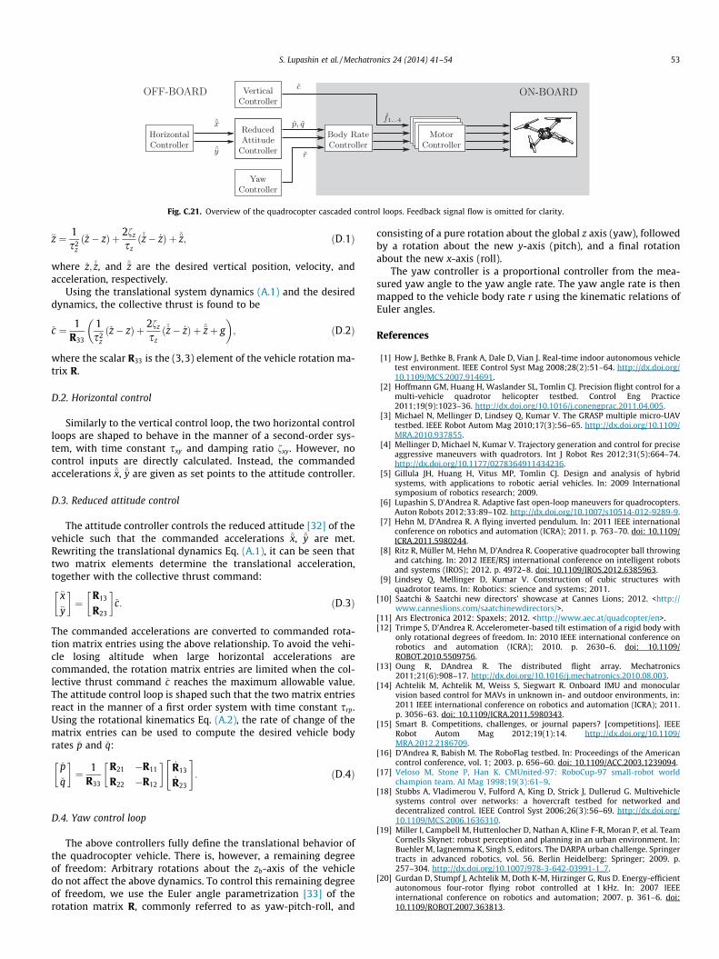
Fig. C.21. Overview of the quadrocopter cascaded control loops. Feedback signal flow is omitted for clarity.
S. Lupashin et al. / Mechatronics 24 (2014) 41–54 53
€z ¼ 1s2
zð�z� zÞ þ 2fz
szð�_z� _zÞ þ �€z; ðD:1Þ
where �z;�_z, and �€z are the desired vertical position, velocity, andacceleration, respectively.
Using the translational system dynamics (A.1) and the desireddynamics, the collective thrust is found to be
�c ¼ 1R33
1s2
zð�z� zÞ þ 2fz
szð�_z� _zÞ þ �€zþ g
� �; ðD:2Þ
where the scalar R33 is the (3,3) element of the vehicle rotation ma-trix R.
D.2. Horizontal control
Similarly to the vertical control loop, the two horizontal controlloops are shaped to behave in the manner of a second-order sys-tem, with time constant sxy and damping ratio fxy. However, nocontrol inputs are directly calculated. Instead, the commandedaccelerations �€x, �€y are given as set points to the attitude controller.
D.3. Reduced attitude control
The attitude controller controls the reduced attitude [32] of thevehicle such that the commanded accelerations �€x, �€y are met.Rewriting the translational dynamics Eq. (A.1), it can be seen thattwo matrix elements determine the translational acceleration,together with the collective thrust command:
€x€y
� �¼
R13
R23
� ��c: ðD:3Þ
The commanded accelerations are converted to commanded rota-tion matrix entries using the above relationship. To avoid the vehi-cle losing altitude when large horizontal accelerations arecommanded, the rotation matrix entries are limited when the col-lective thrust command �c reaches the maximum allowable value.The attitude control loop is shaped such that the two matrix entriesreact in the manner of a first order system with time constant srp.Using the rotational kinematics Eq. (A.2), the rate of change of thematrix entries can be used to compute the desired vehicle bodyrates �p and �q:
�p�q
� �¼ 1
R33
R21 �R11
R22 �R12
� � _R13
_R23
" #: ðD:4Þ
D.4. Yaw control loop
The above controllers fully define the translational behavior ofthe quadrocopter vehicle. There is, however, a remaining degreeof freedom: Arbitrary rotations about the zb-axis of the vehicledo not affect the above dynamics. To control this remaining degreeof freedom, we use the Euler angle parametrization [33] of therotation matrix R, commonly referred to as yaw-pitch-roll, and
consisting of a pure rotation about the global z axis (yaw), followedby a rotation about the new y-axis (pitch), and a final rotationabout the new x-axis (roll).
The yaw controller is a proportional controller from the mea-sured yaw angle to the yaw angle rate. The yaw angle rate is thenmapped to the vehicle body rate r using the kinematic relations ofEuler angles.
References
[1] How J, Bethke B, Frank A, Dale D, Vian J. Real-time indoor autonomous vehicletest environment. IEEE Control Syst Mag 2008;28(2):51–64. http://dx.doi.org/10.1109/MCS.2007.914691.
[2] Hoffmann GM, Huang H, Waslander SL, Tomlin CJ. Precision flight control for amulti-vehicle quadrotor helicopter testbed. Control Eng Practice2011;19(9):1023–36. http://dx.doi.org/10.1016/j.conengprac.2011.04.005.
[3] Michael N, Mellinger D, Lindsey Q, Kumar V. The GRASP multiple micro-UAVtestbed. IEEE Robot Autom Mag 2010;17(3):56–65. http://dx.doi.org/10.1109/MRA.2010.937855.
[4] Mellinger D, Michael N, Kumar V. Trajectory generation and control for preciseaggressive maneuvers with quadrotors. Int J Robot Res 2012;31(5):664–74.http://dx.doi.org/10.1177/0278364911434236.
[5] Gillula JH, Huang H, Vitus MP, Tomlin CJ. Design and analysis of hybridsystems, with applications to robotic aerial vehicles. In: 2009 Internationalsymposium of robotics research; 2009.
[6] Lupashin S, D’Andrea R. Adaptive fast open-loop maneuvers for quadrocopters.Auton Robots 2012;33:89–102. http://dx.doi.org/10.1007/s10514-012-9289-9.
[7] Hehn M, D’Andrea R. A flying inverted pendulum. In: 2011 IEEE internationalconference on robotics and automation (ICRA); 2011. p. 763–70. doi: 10.1109/ICRA.2011.5980244.
[8] Ritz R, Müller M, Hehn M, D’Andrea R. Cooperative quadrocopter ball throwingand catching. In: 2012 IEEE/RSJ international conference on intelligent robotsand systems (IROS); 2012. p. 4972–8. doi: 10.1109/IROS.2012.6385963.
[9] Lindsey Q, Mellinger D, Kumar V. Construction of cubic structures withquadrotor teams. In: Robotics: science and systems; 2011.
[10] Saatchi & Saatchi new directors’ showcase at Cannes Lions; 2012. <http://www.canneslions.com/saatchinewdirectors/>.
[11] Ars Electronica 2012: Spaxels; 2012. <http://www.aec.at/quadcopter/en>.[12] Trimpe S, D’Andrea R. Accelerometer-based tilt estimation of a rigid body with
only rotational degrees of freedom. In: 2010 IEEE international conference onrobotics and automation (ICRA); 2010. p. 2630–6. doi: 10.1109/ROBOT.2010.5509756.
[13] Oung R, DAndrea R. The distributed flight array. Mechatronics2011;21(6):908–17. http://dx.doi.org/10.1016/j.mechatronics.2010.08.003.
[14] Achtelik M, Achtelik M, Weiss S, Siegwart R. Onboard IMU and monocularvision based control for MAVs in unknown in- and outdoor environments, in:2011 IEEE international conference on robotics and automation (ICRA); 2011.p. 3056–63. doi: 10.1109/ICRA.2011.5980343.
[15] Smart B. Competitions, challenges, or journal papers? [competitions]. IEEERobot Autom Mag 2012;19(1):14. http://dx.doi.org/10.1109/MRA.2012.2186709.
[16] D’Andrea R, Babish M. The RoboFlag testbed. In: Proceedings of the Americancontrol conference, vol. 1; 2003. p. 656–60. doi: 10.1109/ACC.2003.1239094.
[17] Veloso M, Stone P, Han K. CMUnited-97: RoboCup-97 small-robot worldchampion team. AI Mag 1998;19(3):61–9.
[18] Stubbs A, Vladimerou V, Fulford A, King D, Strick J, Dullerud G. Multivehiclesystems control over networks: a hovercraft testbed for networked anddecentralized control. IEEE Control Syst 2006;26(3):56–69. http://dx.doi.org/10.1109/MCS.2006.1636310.
[19] Miller I, Campbell M, Huttenlocher D, Nathan A, Kline F-R, Moran P, et al. TeamCornells Skynet: robust perception and planning in an urban environment. In:Buehler M, Iagnemma K, Singh S, editors. The DARPA urban challenge. Springertracts in advanced robotics, vol. 56. Berlin Heidelberg: Springer; 2009. p.257–304. http://dx.doi.org/10.1007/978-3-642-03991-1_7.
[20] Gurdan D, Stumpf J, Achtelik M, Doth K-M, Hirzinger G, Rus D. Energy-efficientautonomous four-rotor flying robot controlled at 1 kHz. In: 2007 IEEEinternational conference on robotics and automation; 2007. p. 361–6. doi:10.1109/ROBOT.2007.363813.
54 S. Lupashin et al. / Mechatronics 24 (2014) 41–54
[21] Sherback M, Purwin O, D’Andrea R. Real-time motion planning and control inthe 2005 Cornell RoboCup system. In: Kozlowski K, editor. Robot motion andcontrol. Lecture notes in control and information sciences, vol. 335. Berlin/Heidelberg: Springer; 2006. p. 245–63. http://dx.doi.org/10.1007/978-1-84628-405-2_16.
[22] Mueller M, D’Andrea R. Critical subsystem failure mitigation in an indoor uavtestbed. In: 2012 IEEE/RSJ international conference on intelligent robots andsystems (IROS); 2012. p. 780–5. doi: 10.1109/IROS.2012.6385910.
[23] Plett GL. Extended Kalman filtering for battery management systems of LiPB-based HEV battery packs part 1: background. J Power Sour 2004;134:252–61.
[24] Müller M, Lupashin S, D’Andrea R. Quadrocopter ball juggling. In: 2011 IEEE/RSJ international conference on intelligent robots and systems (IROS); 2011. p.5113–20. doi: 10.1109/IROS.2011.6094506.
[25] Mueller F, Schoellig A, D’Andrea R. Iterative learning of feed-forwardcorrections for high-performance tracking. In: 2012 IEEE/RSJ internationalconference on intelligent robots and systems (IROS); 2012. p. 3276–81. doi:10.1109/IROS.2012.6385647.
[26] Ambühl A. Human interaction with a quadrocopter using a Kinect sensor.Bachelor thesis, ETH Zürich; 2011.
[27] Augugliaro F, Schoellig A, D’Andrea R. Generation of collision-free trajectoriesfor a quadrocopter fleet: a sequential convex programming approach. In: 2012IEEE/RSJ international conference on intelligent robots and systems (IROS);2012. p. 1917–22. doi: 10.1109/IROS.2012.6385823.
[28] Schoellig AP, Augugliaro F, D’Andrea R. A platform for dance performanceswith multiple quadrocopters. In: Proceedings of the IEEE/RSJ internationalconference on intelligent robots and systems (IROS) – workshop on robots andmusical expressions; 2010. p. 1–8.
[29] Brescianini D, Hehn M, D’Andrea R. Quadrocopter pole acrobatics. In: Proc. ofthe IEEE/RSJ international conference on intelligent robots and systems (IROS);2013.
[30] Augugliaro F, D’Andrea R. Admittance control for physical human–quadrocopter interaction. In: European control conference; 2013.
[31] Hughes PC. Spacecraft attitude dynamics. John Wiley & Sons; 1986.[32] Chaturvedi N, Sanyal A, McClamroch N. Rigid-body attitude control. IEEE
Control Syst 2011;31(3):30–51. http://dx.doi.org/10.1109/MCS.2011.940459.[33] Zipfel PH. Modeling and simulation of aerospace vehicle dynamics. Second
ed. AIAA; 2007.