Embed Size (px)
Citation preview
Continuum Mech. Thermodyn. (2008) 20: 231–254DOI 10.1007/s00161-008-0080-2
ORIGINAL ARTICLE
Maxim A. Zapara · Nikolay D. Tutyshkin ·Wolfgang H. Müller · Kerstin Weinberg · Ralf Wille
A physico-mechanical approach to modeling of metalforming processes—part I: theoretical framework
Received: 10 October 2007 / Accepted: 29 April 2008 / Published online: 8 August 2008© Springer-Verlag 2008
Abstract A combined physico-mechanical approach to research and modeling of forming processes for metalswith predictable properties is developed. The constitutive equations describing large plastic deformations undercomplex loading are based on both plastic flow theory and continuum damage mechanics. The model whichis developed in order to study strongly plastically deformed materials represents their mechanical behaviorby taking micro-structural damage induced by strain micro-defects into account. The symmetric second-rankorder tensor of damage is applied for the estimation of the material damage connected with volume, shape, andorientation of micro-defects. The definition offered for this tensor is physically motivated since its hydrostaticand deviatoric parts describe the evolution of damage connected with a change in volume and shape of micro-defects, respectively. Such a representation of damage kinetics allows us to use two integral measures forthe calculation of damage in deformed materials. The first measure determines plastic dilatation related toan increase in void volume. A critical amount of plastic dilatation enables a quantitative assessment of therisk of fracture of the deformed metal. By means of an experimental analysis we can determine the functionof plastic dilatation which depends on the strain accumulated by material particles under various stress andtemperature-rate conditions of forming. The second measure accounts for the deviatoric strain of voids whichis connected with a change in their shape. The critical deformation of ellipsoidal voids corresponds to theirintense coalescence and to formation of large cavernous defects. These two damage measures are important forthe prediction of the meso-structure quality of metalware produced by metal forming techniques. Experimentalresults of various previous investigations are used during modeling of the damage process.
Keywords Plasticity · Continuum damage mechanics · Metal fracture · Plastic flow · Damage kinetics ·Deformation · Stress · Temperature · Micro-structure · Strain micro-defect · Void · Modeling · Constitutiveequation
PACS 46.35.+z · 81.40.Lm · 61.72.Qq · 46.50.+a · 62.20.mm
Communicated by S. Roux
M. A. Zapara · N. D. TutyshkinDepartment of Technological Mechanics, Tula State University, 300600 Tula, Russia
W. H. Müller (B) · R. WilleInstitut für Mechanik-LKM, Technische Universitat Berlin, Sekretariat MS 02,Einsteinufer 5, 10587 Berlin, GermanyE-mail: [email protected]
K. WeinbergInstitut fur Mechanik und Regelungstechnik - Mechatronik, AG Festkörpermechanik, Universitat Siegen,Paul-Bonatz-Straße 9-11, 57076 Siegen, Germany
232 M. A. Zapara et al.
1 Introduction
Many technological processes of metalware production are based on the combination of forming operations(deformation processing) and heat treatment. The operating characteristics of finished products are substantiallydefined by the mechanical and micro-structural properties of the materials. A leading role in the technologicalcreation of optimized mechanical and micro-structural properties of the materials of finished products isplayed by forming operations. Using models of metal forming processes successfully helps solving problemsappearing during development of state-of-the-art production techniques.
A combined physico-mechanical approach based on the study of both mechanical and micro-structuralproperties amounting to important technological parameters of strained metals is developed for the analysis offorming processes. This approach is founded on advanced methods of plasticity theory which include physico-mechanical models of strained materials, methods for calculation of associated stress and strain rate fields,and methods for determination of mechanical and micro-structural parameters related to technological andoperational characteristics of finished components.
It should be noted that the mathematical and the applied theory of plasticity was developed based onconceptual aspects of continuum mechanics. Basic equations and models in classical plasticity theory [15]describe a mechanical behavior of deformed solids without taking their micro-structural properties (i.e., para-meters of the meso-structure, such as void growth and coalescence, polycrystalline unit grain size, volumefraction of heterogeneous phases, internal energy of hardening, healing of meso-defects at elevated strain tem-peratures, etc.) into consideration. The mechanical characteristics of materials depend on deformation processparameters (e.g., strain extent, rate, and temperature; stress-strain state) and they are determined on the basis ofmacro-experiments for macro-samples [17]. Mechanisms of micro-structural behavior of deformed materialsare not studied in macro-experiments.
Investigations in the field of technological mechanics have shown that operational properties of machinecomponents (e.g., the ability to withstand high strain rates or intense thermal and physico-chemical loads)depend not only on macro-mechanical but also micro-structural characteristics of their materials. In this contextthere is a necessity for the development of a combined physico-mechanical approach to an understandingand modeling of deformation processes of materials. The model for deformed materials should describetheir mechanical behavior taking micro-structural characteristics (e.g., damage by strain micro-defects) intoconsideration. The formulation of the models as well as defining constitutive equations for deformed anddamaged materials with predictable micro-structural and mechanical properties require complex experimentalstudies of the material characteristics depending on the parameters of the deformation processes.
In the publications dedicated to a comprehensive physico-mechanical approach similar to the one presentedin this paper great attention is given
• to the development of a theory of elastic-viscoplastic deformations of crystalline solids (e.g., [4,24,38]);• to studies on meso-structural levels of deformation (e.g., [13,29]);• to a methodology of the underlying physics in continuum mechanics terms as a construction base for
material models with meso-structural properties (e.g., [1,8]);
Less attention is given to the development of the theory of plastic flow of solids when subjected to large finitestrains under complex loading together with a meso-mechanical approach to damage, i.e., effect of grain size,dislocation ensembles, coalescence of voids, etc.
The theory of polycrystal plastic flow finds an application for research and modeling of metal formingprocedures where target properties develop under large finite strains. The use of plastic flow theory is ofparticular current interest for an understanding of the processes during three-axial deformation with strongvariation of stress conditions both in time and within the plastically deformed regions. The combined use ofplastic flow theory and basic concepts of continuum damage mechanics allows us to study the change of theductile properties of processed materials during deformation in view of many factors including nucleation,propagation, growth, coalescence, and possible healing of strain micro-defects. This analysis enables one topredict accurately the strain damage for deformed materials. It is essential when manufacturing metalware tobe used under high and intense loads.
Such combined methods were developed in some previous works. Kolmogorov et al. [21] and Bogatov [3]studied the processes of rolling, dragging, and drawing of metallurgical blanks and predicted the correspon-ding strain damage. Gelin [12] presented finite element models of damage for bulk and sheet metal formingprocesses. Tang et al. [33] used a tensor measure of damage for predicting the material fracture during sheetmetal stamping. Xiang and Wu [39] analyzed and simulated superplastic forming of Al-alloys using a void
A physico-mechanical approach to modeling of metal forming processes 233
damage criterion. Pirondi et al. [30] predicted fracture of low-alloy steels subjected to cyclic plastic loadingon the basis of continuum damage mechanics models. On the basis of both plastic flow theory and dissipativedamage mechanics Makarov et al. [26] studied isothermal super-plastic extrusion of solid shapes made ofcarbon steels (C: 0.75–1.75%).
In the present work the authors use an integrated approach for research and modeling of plastic deformationof metals subjected to complex loading. It is based on plastic flow theory and tensor theory of strain damage.This approach involves determination of consistent stress and plastic flow velocity fields under complex loadingconditions using enhanced models of processed materials. It is particularly appropriate for the analysis anddesign of non-stationary and high-speed forming processes with strong variation of stress and strain rateconditions.
The modeling of deformation processes for materials with predictable structural and mechanical proper-ties is based on the fundamental equations of continuum mechanics, rheological correlations to describe theproperties of solids depending on the deformation, and on experimental data for the formulation of boundaryconditions in arising problems of plasticity theory.
2 Basic equations of metal plastic flow
Plastic strains in deformed metals amount to 70–90% being ≈ 102 larger than elastic strains in metal formingprocesses (e.g., drawing, die forging, extrusion). Thus, the deformed material is considered as a rigid-plasticsolid whose yield strength depends on strain, strain rate, and temperature, as well as the parameters of themesoscopic structure. The calculation of stress-strain state and related parameters of forming processes byusing the model of rigid-plastic solids leads to quite satisfactory results corresponding to experimental data. Theevolution of strain damage results in plastic dilatation. According to test data plastic dilatation of engineeringmaterials does not exceed 2–5 % even at large processing deformations. This fact enables one to make anassumption concerning the materials incompressibility when determining the fields of plastic flow velocities.
The equations relevant for a description of plastic flow of solids (in orthogonal curvilinear coordinatesxi , i = 1, 2, 3) are:
• equilibrium of forces (∇ j covariant differentiation; σ i j contravariant components of the stress tensor;ρ density of the material; ai , Fi contravariant components of acceleration and external force density,respectively):
∇ jσi j = ρ
(ai − Fi
), (1)
• incompressibility condition (υi contravariant components of velocity):
∇iυi = 0, (2)
• yield condition (ei j covariant components of the deviatoric strain; T thermodynamic temperature; χs para-meters related to the local deformation by nonholonomic correlations; µk physico-structural parameters):
f(
si j , ei j , T, χs, µk
)= 0, (3)
• associated flow rule (λ a positive scalar proportional to plastic strain force; si j contravariant stress deviatorcomponents; t time; ei j covariant components of the deviatoric strain rate):
ei j = λ∂ f
∂si j, (4)
• rate equations for the physico-structural parameters:
dµk
dt= µk
(σ i j , ei j , T, χs, µk
). (5)

234 M. A. Zapara et al.
More explicitly we may write (Γ ik j denote the Christoffel symbols, cf., [22]):
∇ jσi j = ∂σ i j
∂x j+ σ k jΓ i
k j + σ ikΓj
k j ,
∇iυi = ∂υi
∂xi+ υkΓ i
ik, ai = ∂υi
∂t+ υ j
(∂υi
∂x j+ υkΓ i
k j
), (6)
ei j = 1
2
(∂υi
∂x j+ ∂υ j
∂xi− 2υkΓ
ki j
).
For orthogonal coordinates the non-vanishing Christoffel symbols can be calculated with the following for-mulae (Hi are parameters related to the metric tensor, gi j , namely Hi = √
gii ):
Γ ii j = 1
Hi
∂Hi
∂x j, Γ i
j j = − Hj
H2i
∂Hj
∂xi. (7)
The six equations shown in (4) are not mutually independent. They can be reduced to three so-calledcoaxiality equations for the deviators of the strain rate and of the stresses (i.e., coincidence of their principalaxes):
ei j
σi j= ei i − e j j
σi i − σ j j≡ ei i − e j j
sii − s j j, i, j = 1, 2, 3, i = j (8)
and a condition of similarity between these deviators
φe = φσ , (9)
where φe and φσ denote the deviator phase angles (Lode angles) which are defined by the following equations:
cos (3φe) = −3√
3I3(ei j
)
2I 3/22
(ei j
) , cos (3φσ ) = −3√
3I3(si j
)
2I 3/22
(si j
) , (10)
where I2(ei j
) = e2, I2(si j
) = s2, and I3(ei j
), I3
(si j
)are second and third invariants of the strain rate and
stress deviators, respectively.In what follows a yield criterion of the von Mises type will be used (τs is the yield stress under shear, see
also Eq. (19) below):
f(
si j , ei j , T, χs, µk
)= 1
2si ·· j s
j ··i − τ 2
s
(ei j , T, χs, µk
) = 0. (11)
For the parameters χs , which are associated with the deformation, the intensity of shear strain rate, Λ, andthe cumulative shear strain, Λ, or Odquist parameter, are used:
Λ =√
2ei ·· j ej ··i , Λ =
∫
s(t)
√2ei ·· j e
j ··i dt, (12)
where ei ·· j denote the mixed components of the strain rate deviator. The parameters Λ andΛ are connected by
the non-holonomic equation dΛ/
dt = Λ. For each strain path, s (t), the parameter Λ can be determined byintegration according to Eq. (12) provided that strain rates ei ·
· j are known.As physico-structural parameters µk we will specifically choose a micro-defect damage parameter ω,
the grain size D of the polycrystal, and the energy characteristic u(µ) of irreversible changes of the crystallattice (viz., a density of the internal energy of hardening, uh). The afore-mentioned structural properties ofengineering materials have a significant influence upon the operating characteristics of finished products.
The analysis of spatial stress and velocity fields dependent on mechanical and structural properties ofdeformed metals is based on a solution of the combined basic Eqs. (1)–(5) using the technique of yield zonemapping in deviatoric stress space [35], which will be explained in greater detail in the second part of thispaper.
A physico-mechanical approach to modeling of metal forming processes 235
3 Associated law of metal plastic flow
The equation for the yield surface (3) together with the flow rule (4) determine an associated law of metal plasticflow. Plastic flow of strained materials is accompanied by rate effects and a structural change that substantiallyaffects the technological parameters and working characteristics of the final products. Rate effects, such asinertial stress, thermal flux, or rate hardening and structural changes are satisfactorily described by the yieldsurface (3). The flow rule (4) establishes correlations between the strain rate ei j (or the increments dei j ), thestrains ei j , and the stresses si j for large plastic deformations.
The structure of the flow rule (4) satisfying the yield condition (3) is determined from the principle ofmaximum power of deformation (Hill 1948):
dλ = λ dt = h d′ f, (13)
where h > 0 is a function of various parameters that define the physico-mechanical conditions of the material.Moreover, d′ f is the differential of the yield function ( f = 0) provided that the strain increments vanish, i.e.,dei j = 0, in contrast to the total differential d f of the yield function (consistency condition):
d f = ∂ f
∂si jdsi j + ∂ f
∂ei jdei j + ∂ f
∂TdT + ∂ f
∂χsdχs + ∂ f
∂µkdµk = 0. (14)
By combination of Eqs. (4) and (13) we obtain dei j = h ∂ f∂si j d′ f . Provided that strain increments are zero,
i.e., dei j = 0, the differential of the yield surface is given by:
d′ f = ∂ f
∂si jdsi j + ∂ f
∂Td (T −Ts)+ ∂ f
∂µkd′µk > 0, (15)
where Ts is a temperature increment related to the dissipated power density w = dwdt
= si j ei j (w denotesthe density of the work of deformation); d′µk is a differential of physico-structural parameters not related tothe deformations ei j . Note that the inequality d′ f > 0 implies a condition of active loading, i.e., of furthercontinuation of plastic deformation.
From Eqs. (13)–(15) it follows that
dλ
h+ ∂ f
∂ei jdei j + ∂ f
∂Td (Ts)+ ∂ f
∂χsdχs + ∂ f
∂µk
(dµk − d′µk
) = 0. (16)
The differentials d (Ts), dχs , dµk − d′µk are related to the strain increments dei j as follows:
d (Ts) = Ksdei j , dχs = Asdei j , dµk − d′µk = Bsdei j (17)
where Ks, As, Bs are functions of the physical and mechanical parameters of materials.Equation (16) is now combined with Eq. (17) to yield:
dλ
h+
(∂ f
∂ei j+ Ks
∂ f
∂T+ As
∂ f
∂χs+ Bs
∂ f
∂µk
)dei j = 0. (18)
By virtue of the associative flow rule (4) the scalar h can now be identified:
h = −(∂ f
∂ei j+ Ks
∂ f
∂T+ As
∂ f
∂χs+ Bs
∂ f
∂µk
)−1 (∂ f
∂si j
)−1
. (19)
The von Mises yield function (11) will be used for finding the scalar dλ = hd′ f . The correspondingdetermination procedure for this function is outlined below. Experiments have been performed and examinedin order to determine the von Mises yield function (11). The experimental data indicate a strong effect of strain,temperature, strain rate, and of the material physico-structural properties on the yield point, i.e.,:
σs = τs√
3 = σs (ei , ei , T, µk) , (20)
where ei = Λ/√
3 denotes the equivalent strains, i.e., an intensity (note the index i in ei ) of cumulative strains,and ei = Λ/
√3 is the corresponding intensity of strain rates.
236 M. A. Zapara et al.
800
600
MPa 1
2
400
200
3
( )issσ
1 - low-carbon steel 2 - Cu-Zn alloy 3 - Al-Mg alloy
0 0.5 1.0 1.5 2.0 2.5 3.0
ie
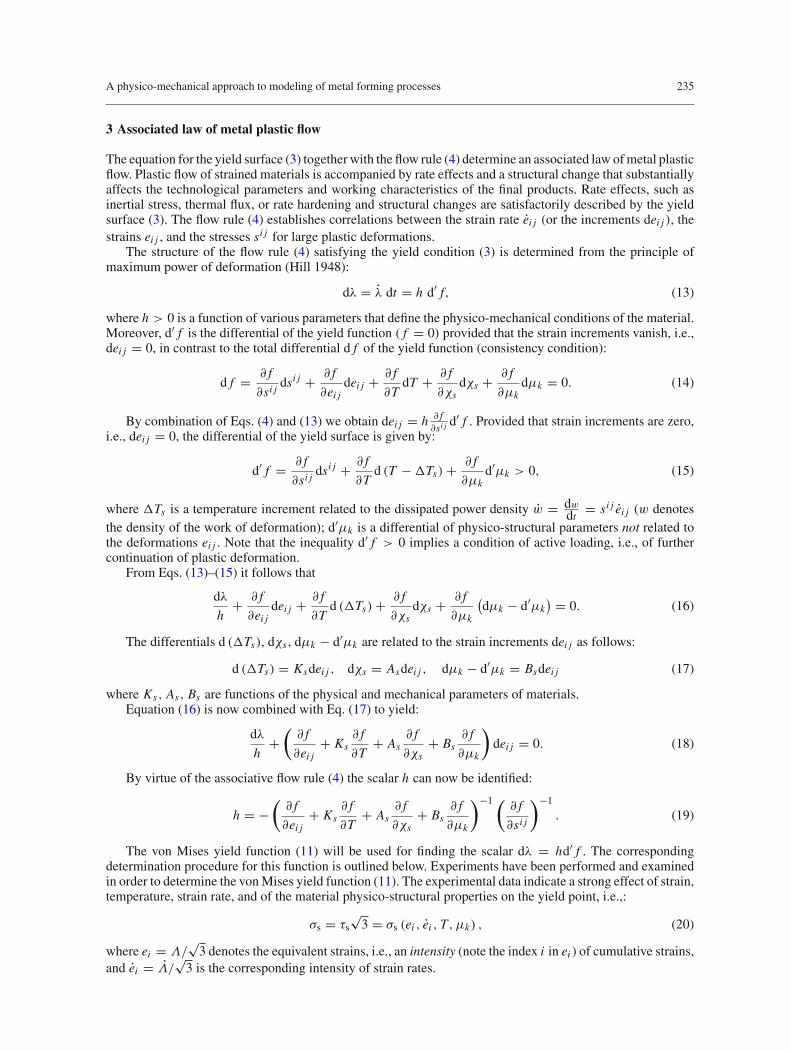
Fig. 1 Isothermal hardening curves
The dependence (20) is represented by the hypersurface ( f = 0) for each material in the space(σs, ei , ei , T, µk). The hypersurface f = 0 can be specified for each material by means of supporting curvesto be constructed by means of the experimental database for various strain conditions. Based on experimentaldata the following mathematical form of non-isothermal hardening curves was established:
σs = σ (is)s exp
[−α
(T − T0
Tmax − T0
)q], (21)
where σ (is)s = σ(is)s (ei , ei0, T0, µk) refer to isothermal hardening curves obtained for various materials at a
fixed strain rate ei0 and an initial temperature T0, cf., Fig. 1. Tmax is the maximum temperature of the process,α and q are parameters used in the equation for the temperature dependent yield strength σs.
Uniaxial compression tests have been made on compound cylindrical specimens in order to obtain hardeningcurves for the investigated metals under isothermal conditions (cf., Fig. 1). Each compound specimen consistedof three identical cylindrical specimens. Plastic compression of the compound specimen allows attaining largedeformations equivalent to those during metal forming processes.
The character of temperature dependence for the yield stress σs (T ) can be described by a decrease in theactivation energy, i.e., by a decrease in the energy threshold required for the movement of dislocations as a resultof thermal fluctuations. Note that the power dependence in (21) can also be motivated from basic principles ofthermodynamics for deformed metals [40,41]. The construction of non-isothermal curves for materials withchanging microstructure is a rather complex problem. It becomes complicated due to the necessity to determinevalues T, α, q which depend on initial conditions and on the strain path s. The change in temperature, T , relatesto both the effect of thermal flux due to the deformation of the material and to the addition or removal of heatas part of the material processing.
The various parameters included in Eq. (21) are determined as follows. The dependency of the isothermalyield point on strain can be approximated by an exponential three-parameter fit:
σ (is)s = σ0.2 + Be(n0−n1ei )i , (22)
where σ0.2 denotes the initial yield point and B, n0, n1 are strain hardening parameters which can be found bythe experimental curve.
During polycrystalline deformation the initial material yield point depends on the grain size. This depen-dence can be physically explained as grain-to-grain strain transfer and it can be quantified by the Hall-Petchcorrelation [40]:
σ0.2 = σ0 + ky D− 12 , (23)
where D is an average grain diameter, σ0 characterizes a resistance of the movement of free dislocations, andky is a measure proportional to the stress σd required for the movement of locked dislocations and dependingon the dislocation arrangement of the metal, i.e.,:
ky = σdl12 , (24)
A physico-mechanical approach to modeling of metal forming processes 237
100
150
200
250
300
MPa 3 2
1
4 mm-1/2
D
σ 0.2
0-1/2
2 6 8 10
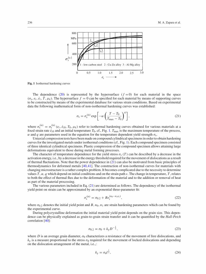
Fig. 2 Effect of grain size D on initial yield point σ0.2 of low-carbon steel for different damage ω (dislocation content); 1: 0.05(107–108 cm−2), 2: 0.25 (109–1010 cm−2), 3: 0.45 (1010 cm−2)
200
300
400
MPa
σd
0.0
ω
2
0.6 0.8
01
0.2 0.4
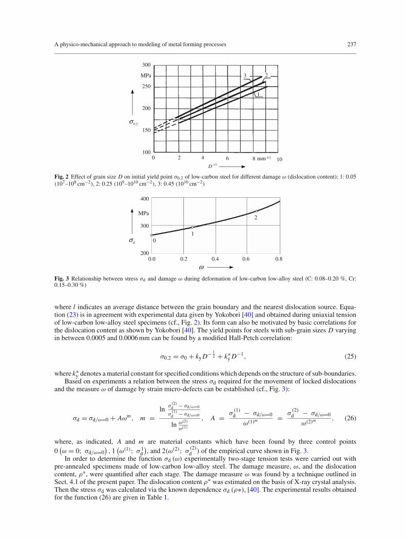
Fig. 3 Relationship between stress σd and damage ω during deformation of low-carbon low-alloy steel (C: 0.08–0.20 %, Cr:0.15–0.30 %)
where l indicates an average distance between the grain boundary and the nearest dislocation source. Equa-tion (23) is in agreement with experimental data given by Yokobori [40] and obtained during uniaxial tensionof low-carbon low-alloy steel specimens (cf., Fig. 2). Its form can also be motivated by basic correlations forthe dislocation content as shown by Yokobori [40]. The yield points for steels with sub-grain sizes D varyingin between 0.0005 and 0.0006 mm can be found by a modified Hall-Petch correlation:
σ0.2 = σ0 + ky D− 12 + k∗
y D−1, (25)
where k∗y denotes a material constant for specified conditions which depends on the structure of sub-boundaries.
Based on experiments a relation between the stress σd required for the movement of locked dislocationsand the measure ω of damage by strain micro-defects can be established (cf., Fig. 3):
σd = σd/ω=0 + Aωm, m =ln
σ(2)d − σd/ω=0
σ(1)d − σd/ω=0
ln ω(2)
ω(1)
, A = σ(1)d − σd/ω=0
ω(1)m = σ
(2)d − σd/ω=0
ω(2)m . (26)
where, as indicated, A and m are material constants which have been found by three control points0
(ω = 0; σd/ω=0
), 1
(ω(1); σ 1
d
), and 2(ω(2); σ (2)d ) of the empirical curve shown in Fig. 3.
In order to determine the function σd (ω) experimentally two-stage tension tests were carried out withpre-annealed specimens made of low-carbon low-alloy steel. The damage measure, ω, and the dislocationcontent, ρ∗, were quantified after each stage. The damage measure ω was found by a technique outlined inSect. 4.1 of the present paper. The dislocation content ρ∗ was estimated on the basis of X-ray crystal analysis.Then the stress σd was calculated via the known dependence σd (ρ∗), [40]. The experimental results obtainedfor the function (26) are given in Table 1.
238 M. A. Zapara et al.
Table 1 Experimental parameters of the function σd (ω) for low-carbon low-alloy steels
Stages of Damage Dislocation content, Stress, σd, MPa Material constantsthe deformation measure, ω ρ∗, cm−2
A, MPa m
Initial state (point 0) 0 108 265 157 1.40First stage of deformation (point 1) 0.26 109 289Second stage of deformation (point 2) 0.66 1011 353
T
1
2
ln( σ
s/ σ
s (is
) )
0.5 Tmax maxT0 T
1
0
2
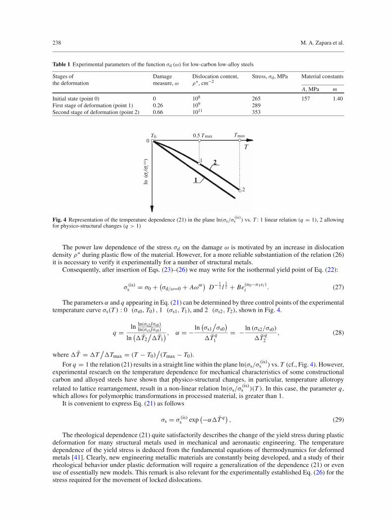
Fig. 4 Representation of the temperature dependence (21) in the plane ln(σs/σ(is)s ) vs. T : 1 linear relation (q = 1), 2 allowing
for physico-structural changes (q > 1)
The power law dependence of the stress σd on the damage ω is motivated by an increase in dislocationdensity ρ∗ during plastic flow of the material. However, for a more reliable substantiation of the relation (26)it is necessary to verify it experimentally for a number of structural metals.
Consequently, after insertion of Eqs. (23)–(26) we may write for the isothermal yield point of Eq. (22):
σ (is)s = σ0 + (σd/ω=0 + Aωm)
D− 12 l
12 + Be(n0−n1ei )
i . (27)
The parameters α and q appearing in Eq. (21) can be determined by three control points of the experimentaltemperature curve σs(T ) : 0 (σs0, T0) , 1 (σs1, T1), and 2 (σs2, T2), shown in Fig. 4.
q = ln ln(σs2/σs0)ln(σs1/σs0)
ln(T2
/T1
) , α = − ln(σs1
/σs0
)
T q1
= − ln (σs2/σs0)
T q2
, (28)
where T = T/Tmax = (T − T0)
/(Tmax − T0).
For q = 1 the relation (21) results in a straight line within the plane ln(σs/σ(is)s ) vs. T (cf., Fig. 4). However,
experimental research on the temperature dependence for mechanical characteristics of some constructionalcarbon and alloyed steels have shown that physico-structural changes, in particular, temperature allotropyrelated to lattice rearrangement, result in a non-linear relation ln(σs/σ
(is)s )(T ). In this case, the parameter q ,
which allows for polymorphic transformations in processed material, is greater than 1.It is convenient to express Eq. (21) as follows
σs = σ (is)s exp(−αT q)
, (29)
The rheological dependence (21) quite satisfactorily describes the change of the yield stress during plasticdeformation for many structural metals used in mechanical and aeronautic engineering. The temperaturedependence of the yield stress is deduced from the fundamental equations of thermodynamics for deformedmetals [41]. Clearly, new engineering metallic materials are constantly being developed, and a study of theirrheological behavior under plastic deformation will require a generalization of the dependence (21) or evenuse of essentially new models. This remark is also relevant for the experimentally established Eq. (26) for thestress required for the movement of locked dislocations.
A physico-mechanical approach to modeling of metal forming processes 239
1.2
1 – low-carbon steel
300 800
c
1.0
0.6
0.4
kJkg K
2 – Cu-Zn alloy
3 – Al-Mg alloy0.8
T
1
12
3.
K
0
0 2
2
0
1
12
400 500 600 700
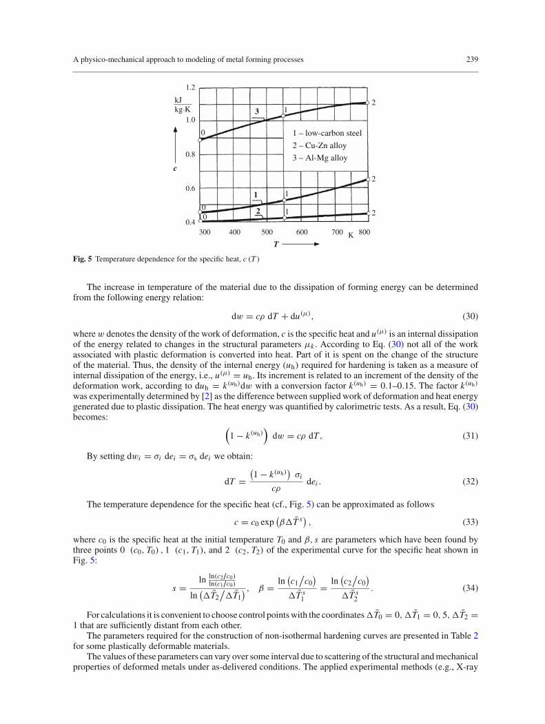
Fig. 5 Temperature dependence for the specific heat, c (T )
The increase in temperature of the material due to the dissipation of forming energy can be determinedfrom the following energy relation:
dw = cρ dT + du(µ), (30)
wherew denotes the density of the work of deformation, c is the specific heat and u(µ) is an internal dissipationof the energy related to changes in the structural parameters µk . According to Eq. (30) not all of the workassociated with plastic deformation is converted into heat. Part of it is spent on the change of the structureof the material. Thus, the density of the internal energy (uh) required for hardening is taken as a measure ofinternal dissipation of the energy, i.e., u(µ) = uh. Its increment is related to an increment of the density of thedeformation work, according to duh = k(uh)dw with a conversion factor k(uh) = 0.1–0.15. The factor k(uh)
was experimentally determined by [2] as the difference between supplied work of deformation and heat energygenerated due to plastic dissipation. The heat energy was quantified by calorimetric tests. As a result, Eq. (30)becomes:
(1 − k(uh)
)dw = cρ dT, (31)
By setting dwi = σi dei = σs dei we obtain:
dT =(1 − k(uh)
)σi
cρdei . (32)
The temperature dependence for the specific heat (cf., Fig. 5) can be approximated as follows
c = c0 exp(βT s) , (33)
where c0 is the specific heat at the initial temperature T0 and β, s are parameters which have been found bythree points 0 (c0, T0) , 1 (c1, T1), and 2 (c2, T2) of the experimental curve for the specific heat shown inFig. 5:
s = ln ln(c2/c0)ln(c1/c0)
ln(T2
/T1
) , β = ln(c1
/c0
)
T s1
= ln(c2
/c0
)
T s2
. (34)
For calculations it is convenient to choose control points with the coordinatesT0 = 0,T1 = 0, 5,T2 =1 that are sufficiently distant from each other.
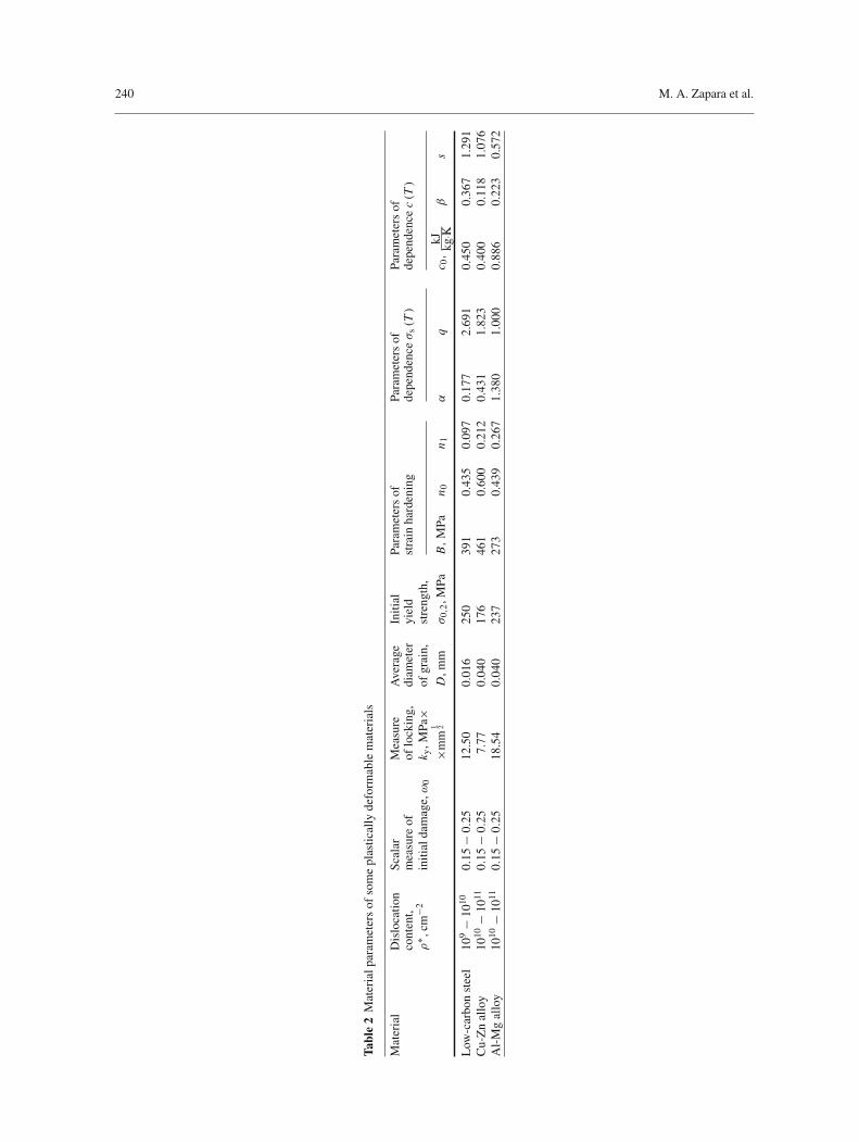
The parameters required for the construction of non-isothermal hardening curves are presented in Table 2for some plastically deformable materials.
The values of these parameters can vary over some interval due to scattering of the structural and mechanicalproperties of deformed metals under as-delivered conditions. The applied experimental methods (e.g., X-ray
240 M. A. Zapara et al.
Tabl
e2
Mat
eria
lpar
amet
ers
ofso
me
plas
tical
lyde
form
able
mat
eria
ls
Mat
eria
lD
islo
catio
nSc
alar
Mea
sure
Ave
rage
Initi
alPa
ram
eter
sof
Para
met
ers
ofPa
ram
eter
sof
cont
ent,
mea
sure
ofof
lock
ing,
diam
eter
yiel
dst
rain
hard
enin
gde
pend
enceσ
s(T)
depe
nden
cec(T)
ρ∗ ,
cm−2
initi
alda
mag
e,ω
0k y
,MPa
×of
grai
n,st
reng
th,
×mm
1 2D
,mm
σ0,
2,M
PaB,
MPa
n 0n 1
αq
c 0,
kJ kg·K
βs
Low
-car
bon
stee
l10
9−
1010
0.15
−0.
2512
.50
0.01
625
039
10.
435
0.09
70.
177
2.69
10.
450
0.36
71.
291
Cu-
Zn
allo
y10
10−
1011
0.15
−0.
257.
770.
040
176
461
0.60
00.
212
0.43
11.
823
0.40
00.
118
1.07
6A
l-M
gal
loy
1010
−10
110.
15−
0.25
18.5
40.
040
237
273
0.43
90.
267
1.38
01.
000
0.88
60.
223
0.57
2

A physico-mechanical approach to modeling of metal forming processes 241
diffraction, electron microscopy, dilatometry, differentially-thermal method, etc.) have a very high accuracyof measurement of material constants. However, a combined use of all these methods during the determinationof the material constants in constitutive equations for the stresses and strains might influence the accuracyin a negative manner. How much this is exactly could be determined inversely by applying these constitutiveequations to complex forming experiments numerically and – under the assumption that, in principle, theseequations describe the material properly – by comparison of the simulations to actual experiments.
In view of σi = σs and substituting σs and c from Eqs. (29), (33) to Eq. (32) we have:
dT =(1 − k(uh)
)σ(is)i exp
(−αT q)
c0ρ exp(βT s
) dei . (35)
Since σ (is)i dei = dw(is)i and T = TmaxT it follows after separation of variables and integration that:
T∫
0
exp(αT q + βT s)d(T
) =(1 − k(uh)
)w(is)i
c0ρTmax. (36)
The auxiliary functions U(T
) = ∫T0 exp(αT q + βT s)d
(T
)and U (ei ) =
(1−k(uh)
)w(is)i
c0ρTmax(cf.,
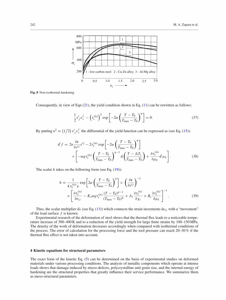
Fig. 6) allow to determine a relation between the deformed specimen temperature increment T and thestrain ei (cf., Fig. 7), i.e., the dependence T (ei , ei0, T0, µk0) in Eq. (21), and then to construct non-isothermalhardening curves (cf., Fig. 8).
1.4
1.2
1.41.2
1.0
0.8
0.6
0.4
1.0
0.8
0.4
0 K
U
0.6 ieTU
0.2 0.2
100 30 500 0.5 1.0 1.5 2.0 2.5 3.00
T
0
ie
Fig. 6 Graphic representation of the function T = T (ei ) by means of the auxiliary functions U (T ) and U (ei ) for thedeformation of low-carbon steel
700
600
strain rate a ime:2 2−
500
nd t
1.5 01 ces ,1−⋅ie& 0.2 01 cesτ
1 – low-carbon steel 2 – Cu-Zn alloy 400
300
3 – Al-Mg alloy
1
2
0 0.5 1.0
T
ie
K
3
= ⋅=
1.5 2.0 2.5 3.0
Fig. 7 Relation between the specimen temperature T and the strain ei
242 M. A. Zapara et al.
8001
600
200
MPa
2
3
400sσ
0 0.5 1.0 1.5 2.0 2.5 3.0
ie
1 - low-carbon steel 2 - Cu-Zn alloy 3 - Al-Mg alloy
Fig. 8 Non-isothermal hardening
Consequently, in view of Eqn (21), the yield condition shown in Eq. (11) can be rewritten as follows:
1
2si ·· j s
j ··i −
(τ (is)s
)2exp
[−2α
(T − T0
Tmax − T0
)q]= 0. (37)
By putting s2 = (1/
2)
si ·· j s
j ··i the differential of the yield function can be expressed as (see Eq. (15)):
d′ f = 2s∂s∂si j
si j − 2τ (is)s exp
[−2α
(T − T0
Tmax − T0
)q]
×[−αqτ (is)s
(T − T0
Tmax − T0
)q−1
d
(T −Ts
Tmax − T0
)+ ∂τ
(is)s
∂µkd′µk
]. (38)
The scalar h takes on the following form (see Eq. (19)):
h = 1
4 τ (is)s sexp
[2α
(T − T0
Tmax − T0
)q]×
(∂s∂si j
)−1
×[∂τ
(is)s
∂ei j− Ksαqτ (is)s
(T − T0)q−1
(Tmax − T0)q + As
∂τ(is)s
∂χs+ Bs
∂τ(is)s
∂µk
]−1
. (39)
Thus, the scalar multiplier dλ (see Eq. (13)) which connects the strain increments dei j with a “movement”of the load surface f is known.
Experimental research of the deformation of steel shows that the thermal flux leads to a noticeable tempe-rature increase of 300–400 K and to a reduction of the yield strength for large finite strains by 100–150 MPa.The density of the work of deformation decreases accordingly when compared with isothermal conditions ofthe process. The error of calculation for the processing force and the tool pressure can reach 20–30 % if thethermal flux effect is not taken into account.
4 Kinetic equations for structural parameters
The exact form of the kinetic Eq. (5) can be determined on the basis of experimental studies on deformedmaterials under various processing conditions. The analysis of metallic components which operate at intenseloads shows that damage induced by micro-defects, polycrystalline unit grain size, and the internal energy ofhardening are the structural properties that greatly influence their service performance. We summarize themas meso-structural parameters.
A physico-mechanical approach to modeling of metal forming processes 243
4.1 Constitutive equations of a tensor theory for strain damage induced by micro-defects
A development of the dislocation arrangement and follow-up dissipative propagation of submicroscopic voidsand submicroscopic cracks occur at the initial stage of deformation. Micro-void generation, growth, coales-cence, and, finally, macro-crack formation (meaning macro-fracture) are observed during further increasingdeformation. The formation of voids is of great importance for the evolution of the strain damage in ductilemetals (cf., e.g., [39,40]).
The experimental work of several researchers allows us to determine a range of the damage values relatedto a nucleation of cavernous defects and discontinuities as a result of the intense coalescence of separate voids(cf., e.g., [3,9,25,34]). Cavernous defects appreciably affect the operating characteristics of finished products.Reaching the critical damage range by the material subjected to working or processing loads can be consideredas a micro-fracture criterion.
Two mechanisms of void generation and growth are possible under plastic deformation of metals:
• due to a vacancy flux under the influence of tensile stresses at grain boundaries;• due to nuclei of voids and discontinuities at triple junctions of grains and nearby large grain-boundary
angles under the action of local stress concentration during grain-boundary slip.
Void formation is promoted by diffusion processes as well as by a low mobility of meso-structural elements(such as sub-grains, particles of inclusions, etc.) where voids arise. As a concept of damage a scalar quantityω is traditionally used in solid mechanics in order to describe the accumulation of defects during deformation(Kachanov, 1986):
dω
dt= ω
(λ(ω)k
), i = 1 , 2 , . . . , (40)
where ω(λ(ω)k ) is a damage rate function of parameters λ(ω)k which are related to a stress state of the formingprocess. The damage value varies within the range ω ∈ [0; 1] where ω = 0 corresponds to the initial state ofthe material (the undamaged structure) and ω = 1 corresponds to the moment of macro-destruction. The straindamage results in plastic dilatation of the structure of the metal. The residual relative increase in volume (i.e.,the linear invariant εi ·
·i of the tensor of plastic strains εi j ) is taken as a measure of plastic dilatation. A criticalvalue εi ·
·icr of plastic dilatation is used to characterize the onset of macro-crack formation.The connection between plastic dilatation and the dissipative formation and growth of strain meso-defects
allows to use the linear invariant εi ··i for the parameter λ(ω)k in Eq. (40), i.e., we put λ(ω)k = εi ·
·i . Thus, the kineticequation (40) can be expressed as:
dω
dt= εi ··iεi ··icr
, (41)
where εi ··i denotes a rate of plastic dilatation.
The known models of void growth [14,27,31] consider the volume fraction of voids as a measure ofdamage:
fv = VvVRV E
, (42)
where Vν denotes the volume occupied by voids within the representative volume element VRV E . Thecorresponding kinetic equation for damage is written as follows:
d fvdt
= (1 − fv) εi ··i , (43)
Equation (43) characterizes a change in damage due to dilatation of the material resulting from void growth(just as the kinetic Eq. (41) does for ω). The differential relation between the measures fν and ω follows fromEqs. (41) and (43):
1
1 − fv
d fvdt
= εi ··icrdω
dt. (44)
244 M. A. Zapara et al.
Table 3 Chemical composition of studied steels
Steel Chemical elements, percents by mass
Fe C W Mo V Cr
Hot-rolled steel Base 0.88 6.05 5.25 1.95 4.01Powdered steel Base 0.97 6.05 5.18 1.91 4.07
While the important role of plastic dilatation as a factor in the assessment of damage for plasticallydeformed metals is unquestioned [26], it is also necessary to note an influence of the shape of the defects andtheir direction on the evolution of the strain damage [16,20,24]. Voids assume an elongated ellipsoidal shapeunder large plastic deformation. At the same time, it turns out that a spatial orientation of the principal axes ofthe meso-ellipsoids is related to the directions of the principal strains ε1, ε2, ε3 of material particles containinga void. Thus, metals possess tensor properties of strain damage [5,28]. In order to estimate the damage ofdeformed materials, which is related to volume, shape, and direction of defects, we introduce a symmetricsecond-rank order tensor ωi j by the following differential equation:
dωi j
dt= ωi j (λ
(ω)k ), k = 1, 2, . . . , (45)
where ωi j (λ(ω)k ) denotes the dependence of the strain damage tensor on the parameters related to the stress
state of the processes.Decomposition of the tensor of damage increments dωi j = ωi j dt into the hydrostatic tensor dωi i and the
deviator dωi j makes clear physical sense: the hydrostatic tensor dωi i describes the damage increment caused
by a change in volume, and the deviator dωi j accounts for the damage increment related to a change of defectshape. Such a view on damage kinetics enables us to apply two integral measures for damage assessment,namely:
ω1 =∫
λ(ω)k (t)
I1
[ωi j
(λ(ω)k
)]dt =
∫
λ(ω)k (t)
ωi ··i
(λ(ω)k
)dt,
(46)ω2 = 2
∫
λ(ω)k (t)
√I2
[ωi j
(λ(ω)k
)]dt =
∫
λ(ω)k (t)
√2ω· j
i · ω·ij ·dt ≡∫
λ(ω)k (t)
√2
(ωi ·· j ω
j ··i − ωi ··i ω
j ·· j
)dt,
where I1(ωi j
)and I2(
ωi j ) are the first invariant of the damage rate tensor ωi j and the second invariant of the
damage rate deviator ωi j , respectively. In physical terms the measure ω1 in Eq. (46) is identically equal to the
same measure ω in dissipative damage theory (Eqs. (40), (41)). This correspondence allows us to determineω1 by solving Eq. (41).
In view of the relationship εi ··i (Λ) between the plastic dilatation and the cumulative strain (cf., Eq. (12))
Eq. (41) becomes:
dω1
dt= 1
εi ··i (Λlim)· dεi ··i (Λ)
dΛ· dΛ
dt≡
[εi ··i (Λ)
] ′Λεi ··i (Λlim)
. (47)
where Λlim denotes a limit value of shear strain corresponding to the point of destruction, and the dash refersto differentiation with respect to Λ.
The function εi ··i (Λ) can be determined on the basis of a pycnometric analysis of change of the initial
density of deformed materials. Plastic dilatation was studied for multi-component alloyed steels made by twomanufacturing techniques: hot rolling and powder metallurgy (cf., Table 3). These steels are of essentiallydifferent grain structures. The powdered steel has finer ferrite grains and evenly distributed small carbidesin contrast to the hot-rolled steel (cf., Table 4). The values of the structural parameters were obtained byradiographic analysis. The selection of two materials with identical chemical compositions and essentiallydifferent micro-structures allows us to study an effect of their micro-structural properties on the evolution ofstrain damage. The test specimens were subjected to uniaxial tension up to their macro-destruction (fracture).

A physico-mechanical approach to modeling of metal forming processes 245
Table 4 Structural parameters of studied steels
Steel ρ∗, cm−2 Ferrite lattice Ferrite grain Carbide Distance between Phase, percents by volumeparameter, nm size, µm size, µm carbides, µm
Carbide Carbide FerriteM6C MC
Hot-rolled 5 × 10¹¹ 0.2872 11.3 − 14.5 2.90 − 3.70 3.3 − 4.1 15 2 83steelPowdered 109 0.2871 3.7 − 4.5 0.99 − 1.21 0.73 − 0.87 14 4 82steel
0 0.4 0.8 1.2 2.01.6Λ
0.02
0.04
0.06
K1
K2K4
K3
0 0.4 0.8 1.2 1.6 2.0Λ
K1
0.06
K2 K4 K3
⋅⋅iiε ⋅
⋅iiε0.02
0.04
′3K
′3
11
1 1
O O K
Fig. 9 Plastic dilatation (εi ··i ) dependence on shear strain (Λ): left hot-rolled steel (C 0,88 %, W 6,05 %, Mo 5,25 %, V 1,95 %,Cr 4,01 %); right powdered steel (C 0,97 %, W 6,05 %, Mo 5,18 %, V 1,91 %, Cr 4,07 %); K1 20C; K2 750C; K3 830C; K4870C; dashed line linear model of plastic dilatation
Table 5 Parameters of plastic dilatation of studied steels
Parameters Hot-rolled steel Powdered steel
Strain temperature C 20 750 810 − 825 850 20 750 810 − 825 850a 1.170 1.000 0.339Λ+1.259 1.000 1.484 1.000 0.291Λ+1.212 1.000b 0.092 0.049 0.0279 0.043 0.218 0.043 0.0147 0.038
Table 6 Temperature of phase transformations (results from the dilatometric analysis)
Material Point Ac1C Point ASP
C
Hot-rolled steel 830 − 840 880 − 890Powdered steel 815 − 825 870 − 880
In Fig. 9 the experimentally determined dependence of plastic dilatation on strain is shown for varioustemperatures for two multi-component alloyed steels.
The dependencies obtained for the plastic dilatation of steels allow us to draw the following conclusions.The experimental dependence εi ··i (Λ) can be approximated by the following power function:
εi ··i = bΛa, (48)
where a and b have been found by control points 1(εi ··i1,Λ1
)and K
(εi ··icr,Λlim
)of the experimental curve
εi ··i (Λ) (cf., Table 5):
a = ln(εi ··icr
/εi ··i1
)
ln(Λlim
/Λ1
) , b = εi ··i1Λa
1= εi ·
·icr
Λalim. (49)
The point K corresponds to the moment of fracture (cf., Fig. 9).For cold deformation the function of plastic dilatation (48) assumes an exponent a > 1 (Fig. 9, curve
O K1). In the case of under-hot and hot forming the experimental diagrams O K2 and O K4 are very closeto linear approximations. For such conditions a linear dependence with a = 1 is used. Super-plastic (SP)forming of steels was realized in the temperature interval [Ac1; ASP] corresponding to the diffusive phasetransformation (α → γ ) of the investigated steels (cf., Table 6). Therefore, a more complex function with a
246 M. A. Zapara et al.
variable exponent a = a (Λ) is required for super-plastic deformation (Fig. 9, curve O K3):
εi ··i = bΛa(Λ) = bΛ(l1Λ+l0). (50)
The condition d2εi ··i/
dΛ2 = 0 in the inflection point K ′3 is added to Eq. (49) for calculating b, l0, l1. Thus,
a third dependence between these parameters results:
1
Λ
(l1 − l0
Λ
)+
(l1 lnΛ+ l1 + l0
Λ
)2
= 0. (51)
The crucial stage of super-plastic deformation is the evolution of the inflection point K ′3, which separates
the areas of delayed (O K ′3) and the accelerated (K ′
3K3) development of damage in steels.In view of Eq. (48) the differential equation (47) and integral dependency (46) for ω1 now become:
dω1
dt=
[bΛa(Λ)
]′Λ
bΛalim
≡( aΛ
+ a′ lnΛ)ΛaΛ
Λalim
, ω1 =∫
Λ(t)
( aΛ
+ a′ lnΛ)ΛaΛ
Λalim
dt. (52)
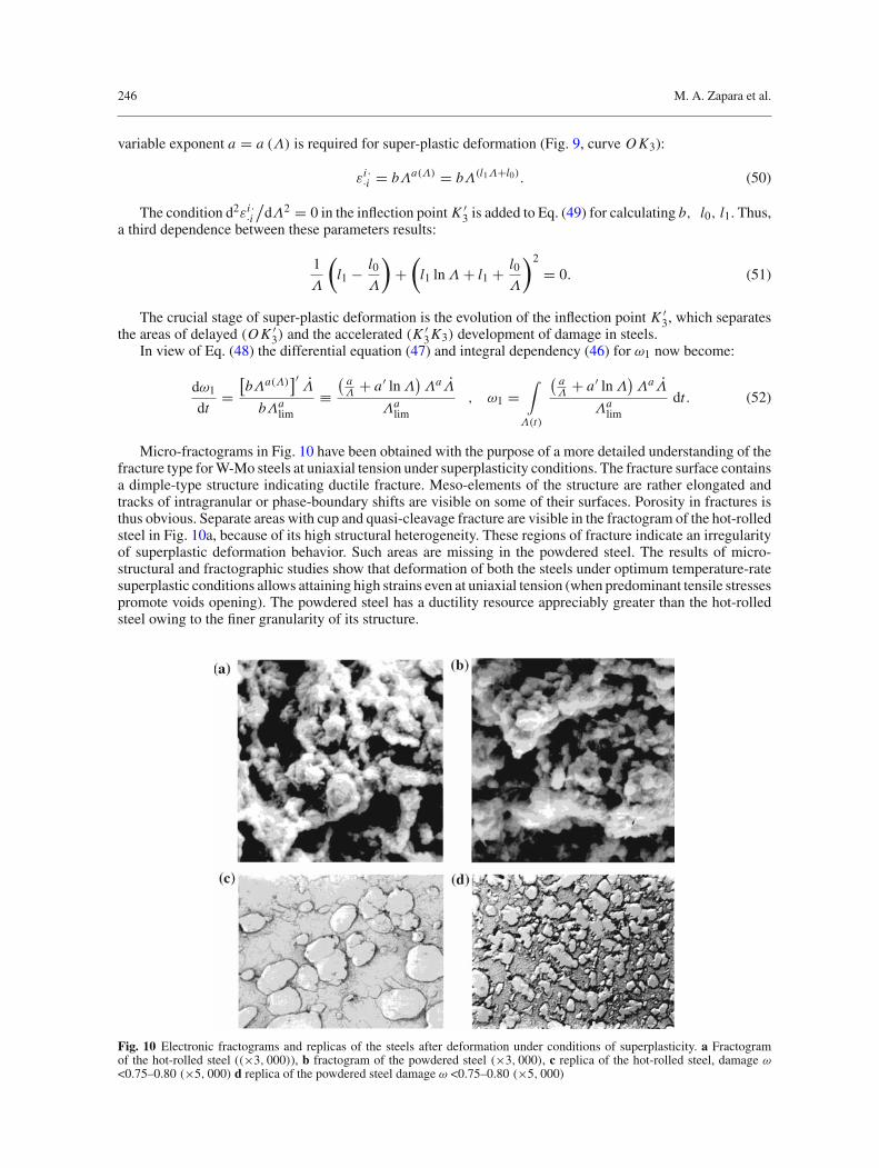
Micro-fractograms in Fig. 10 have been obtained with the purpose of a more detailed understanding of thefracture type for W-Mo steels at uniaxial tension under superplasticity conditions. The fracture surface containsa dimple-type structure indicating ductile fracture. Meso-elements of the structure are rather elongated andtracks of intragranular or phase-boundary shifts are visible on some of their surfaces. Porosity in fractures isthus obvious. Separate areas with cup and quasi-cleavage fracture are visible in the fractogram of the hot-rolledsteel in Fig. 10a, because of its high structural heterogeneity. These regions of fracture indicate an irregularityof superplastic deformation behavior. Such areas are missing in the powdered steel. The results of micro-structural and fractographic studies show that deformation of both the steels under optimum temperature-ratesuperplastic conditions allows attaining high strains even at uniaxial tension (when predominant tensile stressespromote voids opening). The powdered steel has a ductility resource appreciably greater than the hot-rolledsteel owing to the finer granularity of its structure.
Fig. 10 Electronic fractograms and replicas of the steels after deformation under conditions of superplasticity. a Fractogramof the hot-rolled steel ((×3, 000)), b fractogram of the powdered steel (×3, 000), c replica of the hot-rolled steel, damage ω<0.75–0.80 (×5, 000) d replica of the powdered steel damage ω <0.75–0.80 (×5, 000)
A physico-mechanical approach to modeling of metal forming processes 247
An electronic-micro-structural analysis of the specimens obtained under stage-by-stage deformation hasbeen carried out to study the evolution of structural damage. The analysis of electronic replicas (Fig. 10c,d) allows to reveal a stage of active voids coalescence. For these steels the intense voids coalescence occursunder deformation corresponding to damage ω1 > 0.75–0.85. The obtained results are very important for adefinition of operational strain in the manufacturing processes designed for the products with high workingcharacteristics.
The kinetic equation (47) contains the limit strain Λlim. Experimental research by [6] shows that themetal ductility (i.e., the limiting strain) is effected by stress state, temperature-speed conditions of processing,chemistry and the structure of metals, i.e.:
Λlim = Λlim
(σ i j , ei j , T, µk
). (53)
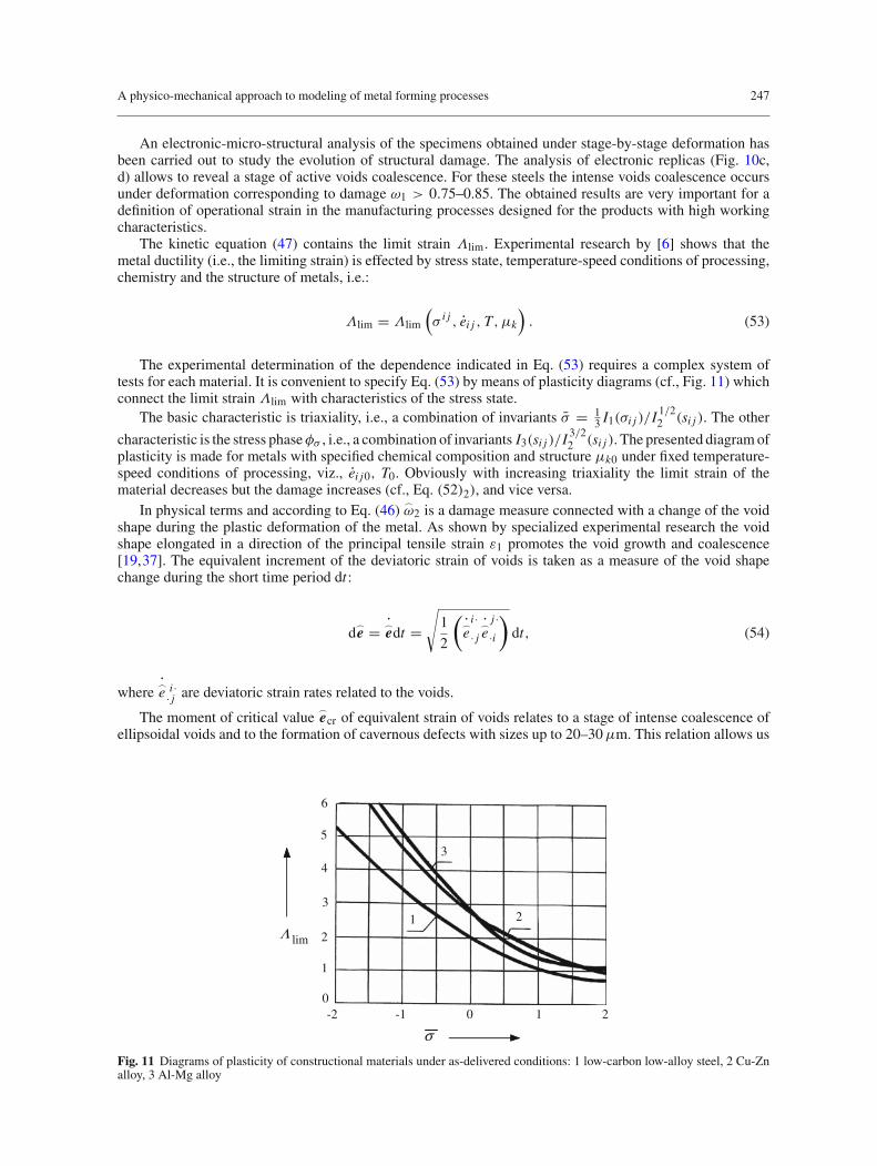
The experimental determination of the dependence indicated in Eq. (53) requires a complex system oftests for each material. It is convenient to specify Eq. (53) by means of plasticity diagrams (cf., Fig. 11) whichconnect the limit strain Λlim with characteristics of the stress state.
The basic characteristic is triaxiality, i.e., a combination of invariants σ = 13 I1(σi j )/I 1/2
2 (si j ). The other
characteristic is the stress phaseφσ , i.e., a combination of invariants I3(si j )/I 3/22 (si j ). The presented diagram of
plasticity is made for metals with specified chemical composition and structure µk0 under fixed temperature-speed conditions of processing, viz., ei j0, T0. Obviously with increasing triaxiality the limit strain of thematerial decreases but the damage increases (cf., Eq. (52)2), and vice versa.
In physical terms and according to Eq. (46) ω2 is a damage measure connected with a change of the void
shape during the plastic deformation of the metal. As shown by specialized experimental research the voidshape elongated in a direction of the principal tensile strain ε1 promotes the void growth and coalescence[19,37]. The equivalent increment of the deviatoric strain of voids is taken as a measure of the void shapechange during the short time period dt :
de =
edt =√
1
2
(e
i ·· je
j ··i
)dt, (54)
wheree · j
i · are deviatoric strain rates related to the voids.
The moment of critical valueecr of equivalent strain of voids relates to a stage of intense coalescence of
ellipsoidal voids and to the formation of cavernous defects with sizes up to 20–30µm. This relation allows us
6
5
43
3
1
-2 -1 0 2
1 2
2
0
limΛ
σ1
Fig. 11 Diagrams of plasticity of constructional materials under as-delivered conditions: 1 low-carbon low-alloy steel, 2 Cu-Znalloy, 3 Al-Mg alloy
248 M. A. Zapara et al.
to formulate the following kinetic equation:
εcrecr
dω2
dt= dω2
dt=
eecr
, (55)
where ω2 =(εcr
/ecr
)ω2.
The normalizing factor εcr/ecr allows us to introduce the damage measure ω2 ∈ [0; 1] which is convenient
for comparing the calculations. Interval boundaries correspond to the initial (strainless) state of the materialand to a stage of intense void coalescence (the micro-fracture stage). The integrated value of the parameterreads:
ω2 =∫
t
eecr
dt ≡∫
t
√(1/
2) (
e · j
i ·e ·ij ·)
ecr
dt =∫
t
εcrecr
√1
2ω· j
i · ω· ji ·dt ≡
∫
t
εcrecr
√1
2
(ωi ·
· j ωj ··i − ωi ·
·i ωj ·· j
)dt.
(56)
For calculating the damage parameter ω2 during plastic flow of metals it is necessary to construct ageometrical model to describe the change of the shape of the void. Stresses, strains, strain rates and temperaturesas well as connected properties of the deformed material studied in continuum mechanics are local parameters,i.e., they relate to small volumes (V ). Small volumes V of engineering metals (with linear dimensionss = 35–140µm) include meso-volumes (Vmeso) with meso-structural elements (grains, voids, dislocationcells with linear dimensionssmeso = 3–18 µm). Thus, the volume ratio isVmeso
/V = (6.3–21.3)×10−4.
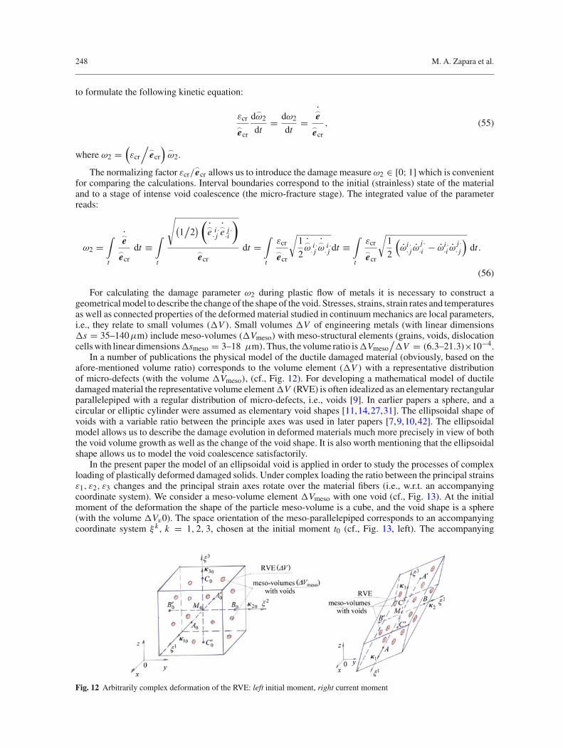
In a number of publications the physical model of the ductile damaged material (obviously, based on theafore-mentioned volume ratio) corresponds to the volume element (V ) with a representative distributionof micro-defects (with the volume Vmeso), (cf., Fig. 12). For developing a mathematical model of ductiledamaged material the representative volume elementV (RVE) is often idealized as an elementary rectangularparallelepiped with a regular distribution of micro-defects, i.e., voids [9]. In earlier papers a sphere, and acircular or elliptic cylinder were assumed as elementary void shapes [11,14,27,31]. The ellipsoidal shape ofvoids with a variable ratio between the principle axes was used in later papers [7,9,10,42]. The ellipsoidalmodel allows us to describe the damage evolution in deformed materials much more precisely in view of boththe void volume growth as well as the change of the void shape. It is also worth mentioning that the ellipsoidalshape allows us to model the void coalescence satisfactorily.
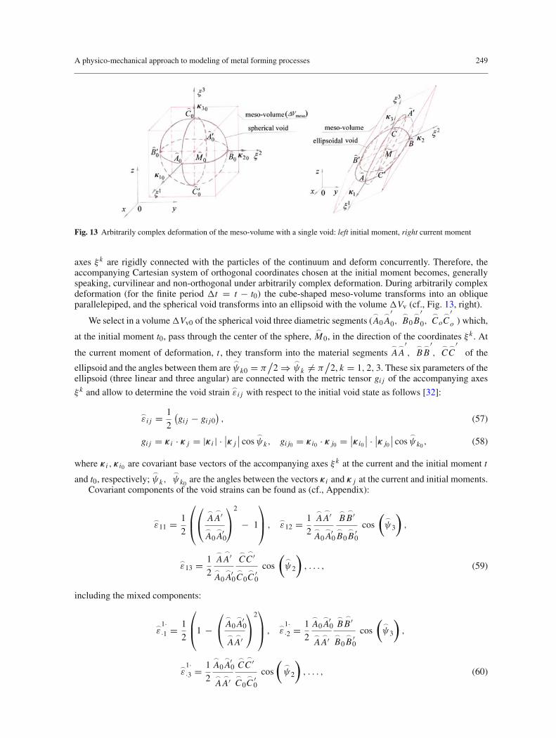
In the present paper the model of an ellipsoidal void is applied in order to study the processes of complexloading of plastically deformed damaged solids. Under complex loading the ratio between the principal strainsε1, ε2, ε3 changes and the principal strain axes rotate over the material fibers (i.e., w.r.t. an accompanyingcoordinate system). We consider a meso-volume element Vmeso with one void (cf., Fig. 13). At the initialmoment of the deformation the shape of the particle meso-volume is a cube, and the void shape is a sphere(with the volume Vv0). The space orientation of the meso-parallelepiped corresponds to an accompanyingcoordinate system ξ k, k = 1, 2, 3, chosen at the initial moment t0 (cf., Fig. 13, left). The accompanying
Fig. 12 Arbitrarily complex deformation of the RVE: left initial moment, right current moment
A physico-mechanical approach to modeling of metal forming processes 249
Fig. 13 Arbitrarily complex deformation of the meso-volume with a single void: left initial moment, right current moment
axes ξ k are rigidly connected with the particles of the continuum and deform concurrently. Therefore, theaccompanying Cartesian system of orthogonal coordinates chosen at the initial moment becomes, generallyspeaking, curvilinear and non-orthogonal under arbitrarily complex deformation. During arbitrarily complexdeformation (for the finite period t = t − t0) the cube-shaped meso-volume transforms into an obliqueparallelepiped, and the spherical void transforms into an ellipsoid with the volume Vv (cf., Fig. 13, right).
We select in a volumeVv0 of the spherical void three diametric segments (
A0
A′0,
B0
B′0,
Co
C′o )which,
at the initial moment t0, pass through the center of the sphere,
M0, in the direction of the coordinates ξ k . At
the current moment of deformation, t , they transform into the material segments
A
A′,
B
B′,
C
C′
of the
ellipsoid and the angles between them are
ψk0 = π/
2 ⇒
ψk = π/
2, k = 1, 2, 3. These six parameters of theellipsoid (three linear and three angular) are connected with the metric tensor gi j of the accompanying axes
ξ k and allow to determine the void strain ε i j with respect to the initial void state as follows [32]:
ε i j = 1
2
(gi j − gi j0
), (57)
gi j = κ i · κ j = |κ i | · ∣∣κ j∣∣ cos
ψk, gi j0 = κ i0 · κ j0 = ∣∣κ i0
∣∣ · ∣∣κ j0
∣∣ cos
ψk0, (58)
where κ i , κ i0 are covariant base vectors of the accompanying axes ξ k at the current and the initial moment t
and t0, respectively;
ψk,
ψk0are the angles between the vectors κ i and κ j at the current and initial moments.
Covariant components of the void strains can be found as (cf., Appendix):
ε11 = 1
2
⎛⎜⎝
⎛⎝
A
A′
A0
A0′
⎞⎠
2
− 1
⎞⎟⎠ ,
ε12 = 1
2
A
A′
A0
A0′
B
B ′
B0
B0′
cos
(
ψ3
),
ε13 = 1
2
A
A′
A0
A0′
C
C ′
C0
C0′
cos
(
ψ2
), . . . , (59)
including the mixed components:
ε
1··1 = 1
2
⎛⎜⎝1 −
⎛⎝
A0
A0′
A
A′
⎞⎠
2⎞⎟⎠ ,
ε
1··2 = 1
2
A0
A0′
A
A′
B
B ′
B0
B0′
cos
(
ψ3
),
ε
1··3 = 1
2
A0
A0′
A
A′
C
C ′
C0
C0′
cos
(
ψ2
), . . . , (60)
250 M. A. Zapara et al.
which are required for the calculation of the volumetric (εi ··i ) and the deviatoric (
e) strain of the voids. The
principal strains ε1,
ε2,
ε3 can be found by solving the characteristic equation for the strain tensor:
ε1 = 1
3ε ·i
i · + 2√3
e cos
(φe − π
3
),
ε2 = 1
3ε ·i
i · + 2√3
e cos
(φe + π
3
),
ε3 = 1
3ε ·i
i · + 2√3
e cos φe, (61)
where φe is the Lode angle for the strains.An experimental determination of the changing sizes of voids is connected with great technical difficulties
[23]. This is why we will make use of statistical characteristics of void formation. For instance, the averagedcharacteristics of the void strain for the present elementary volume V can be applied within each RVE.A corresponding measure is the strain (εi j ) of RVE. If at the initial moment t0 we select in the volumeelement three material segments (A0 A′
0, B0 B ′0,CoC ′
0 ) which pass through the center M0 in the direction ofthe coordinates ξ k then they will transform into material segments AA′, B B ′, CC ′ at the current momentt , and the angles between them will be ψk0 = π
/2 ⇒ ψk = π
/2, k = 1, 2, 3. These six parameters of the
RVE allow us to determine its strains εi j by relations analogous to those for the void strain. The hypothesisthat it is possible to model the void deformation by using the strain measures of the material volume elementrequires a detailed experimental verification. The experimental justification of this hypothesis will allow us topredict shape changes and coalescence of voids by means of accompanying axes plotted as coordinate gridson deformed specimens and manufacturing half-stuff.
The determination of the critical equivalent strainecr of voids in the investigated materials is based on
electron-probe analysis of the void coalescence in test specimens during their stage-by-stage plastic deforma-tion. Obtained electronic replicas allow us to detect a stage of intense void coalescence into large cavernousdefects (discontinuity flaws). The combined use of two damage measures, ω1 and ω2, (in contrast to usingonly ω1 as in previous publications) allows us to predict not only a risk of macro-fracture of the deformedmaterial but also a stage of formation of large cavernous defects due to coalescence of voids taking a change intheir shape and orientation into account. This approach is necessary when producing metalware to be operatedunder intense load and thermal action, high pressure and strain rate. It can be explained by the indisputablefact that a high-quality micro-structure of the metal (without large cavernous defects and clusters) essentiallyimproves an ability of metallic components to withstand dynamic impact loads and also enhances their fatigueresistance. Such products and components are widely used in aerospace, automotive and energy engineering.
4.2 Grain size and internal hardening energy
An essential structural parameter of the deformed metal is the grain size (diameter D). The experimental databy [2] show that strain Λ, temperature T and strain rate Λ effect the grain size of processed metals, i.e.:
dD
dt= D (Λ, H, T, µk) . (62)
Three-dimensional diagrams representing the grain size dependent on strain and temperature (recrystalliza-tion diagrams) can be obtained by integrating Eq. (62) for the materials with a specified initial micro-structureµko and strain rate Λ0:
D (Λ, T, Λ0, µk0) =Λ∫
0
T∫
T0
D′ (Λ, T, Λ0, µk0)
dΛ dT . (63)
These integrals represent a set of hypersurfaces in the phase space D,Λ, Λ, T, µk . For calculationsit is convenient to use a set of plane curves D = D (Λ, T0, Λ0, µk0) for describing the surface D =D (Λ, T, Λ0, µk0). Experimental studies in die forging of low-carbon low-alloy steels allow us to formu-late the following form of Eq. (62):
dD
dt= −γ (Λ−Λ0)
p−1ΛD0 exp[−γ (Λ−Λ0)
p] , (64)
A physico-mechanical approach to modeling of metal forming processes 251
where D0 is the grain size corresponding to the initial shear strainΛ0; γ (T ) , p (T ) are parameters determinedby experimental control points.
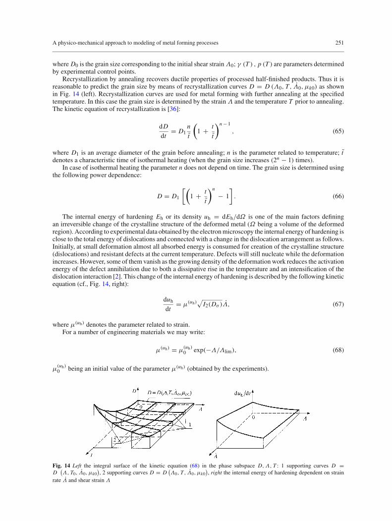
Recrystallization by annealing recovers ductile properties of processed half-finished products. Thus it isreasonable to predict the grain size by means of recrystallization curves D = D (Λ0, T, Λ0, µk0) as shownin Fig. 14 (left). Recrystallization curves are used for metal forming with further annealing at the specifiedtemperature. In this case the grain size is determined by the strainΛ and the temperature T prior to annealing.The kinetic equation of recrystallization is [36]:
dD
dt= D1
n
t
(1 + t
t
)n − 1
, (65)
where D1 is an average diameter of the grain before annealing; n is the parameter related to temperature; tdenotes a characteristic time of isothermal heating (when the grain size increases (2n − 1) times).
In case of isothermal heating the parameter n does not depend on time. The grain size is determined usingthe following power dependence:
D = D1
[(1 + t
t
)n
− 1
]. (66)
The internal energy of hardening Eh or its density uh = dEh/dΩ is one of the main factors definingan irreversible change of the crystalline structure of the deformed metal (Ω being a volume of the deformedregion). According to experimental data obtained by the electron microscopy the internal energy of hardening isclose to the total energy of dislocations and connected with a change in the dislocation arrangement as follows.Initially, at small deformation almost all absorbed energy is consumed for creation of the crystalline structure(dislocations) and resistant defects at the current temperature. Defects will still nucleate while the deformationincreases. However, some of them vanish as the growing density of the deformation work reduces the activationenergy of the defect annihilation due to both a dissipative rise in the temperature and an intensification of thedislocation interaction [2]. This change of the internal energy of hardening is described by the following kineticequation (cf., Fig. 14, right):
duh
dt= µ(uh)
√I2(Dσ )Λ, (67)
where µ(uh) denotes the parameter related to strain.For a number of engineering materials we may write:
µ(uh) = µ(uh)0 exp(−Λ/Λlim), (68)
µ(uh)0 being an initial value of the parameter µ(uh) (obtained by the experiments).
Fig. 14 Left the integral surface of the kinetic equation (68) in the phase subspace D,Λ, T : 1 supporting curves D =D
(Λ, T0, Λ0, µk0
), 2 supporting curves D = D
(Λ0, T, Λ0, µk0
), right the internal energy of hardening dependent on strain
rate Λ and shear strain Λ
252 M. A. Zapara et al.
5 Conclusions and outlook
Plastic flow theory and continuum damage mechanics provide a theoretical and methodological framework forresearch and modeling of forming processes for metalware with optimum service properties. Such a combinedbasis allows us to solve the following problems:
• to formulate a system of constitutive equations for modeling and analyzing metal forming processes togetherwith the prediction of meso-structural properties of deformed materials;
• to create associated physico-mechanical models for the strained material which will describe not onlyits mechanical behavior but also essential physics properties at a meso-structural level (strain damage,polycrystal unit grain size, internal energy of hardening).
The developed system of basic governing Eqs. (1)–(12) describes large plastic deformations under complexloading conditions typical for a number of metal forming processes (e.g., deep-drawing, die forging, extrusion,super-plastic forming). The possibility of the analysis of non-stationary plastic flow in such forming processesis very important. This necessitates the stage-by-stage determination of the stress-strain state and relatedmeso-structural parameters.
The von Mises yield function includes the yield stress depending on strain, strain rate, temperature, andparameters of the meso-structure. Representation of the yield stress dependence (20) by the hypersurface f = 0in the phase space σs, ei , ei , T, µk allows its specification for each material by means of non-isothermal har-dening curves obtained by tests for different deformation conditions. Based on the systematized experimentaldata the power dependence (21) of the yield stress on the temperature is proposed. It also arises from thefundamental principles of thermodynamics for deformed metals. The plotting technique for non-isothermalcurves is presented for materials with a variable meso-structure when a change in temperature, T , is connectedwith a thermal flux effect during the deformation depending on the strain path, s.
Meso-structural damage parameters of deformed materials appreciably affect the operating characteristicsof finished products. A tensor theory of strain damage induced by micro-defects is of great importance from thepoint of view of a combined physico-mechanical approach. The method offered for determining the symmetricsecond-rank order tensor of damage makes physical sense as this tensor is decomposed into hydrostaticand deviatoric parts: The hydrostatic tensor describes the evolution of damage connected with a change involume, while the deviator describes the evolution of damage connected with a change in defect shape. Sucha representation of damage kinetics allows to use two integral measures, ω1 and ω2. These measures are veryimportant for the estimation of the meso-structure quality of metalware produced by metal forming techniquesand subjected to intense power and thermal loads, high strain rates, physico-chemical actions.
A successful practical application of the tensor theory requires rather laborious experimental research ondamage kinetics for deformed materials under complex loading. The most urgent problem is the experimentalcharacterization of the material constants appearing in the constitutive equations for damage. Critical plasticdilatation, εi ·
·i , limiting cumulative strain, Λlim, critical equivalent strain of void,ecr are necessary to be
considered among these material constants.Results of the calculations of material constants and parameters relevant to the defining relations were
given only for selected materials. Performing similar calculations for other materials will require furthercomplex experiments at the meso-level. Indeed, such experiments will allow us to create a well-foundeddatabase for meso-structural properties of plastically deformed materials which is a prerequisite for computersimulations. The presented basic relations and rheological dependencies describe large plastic deformationof many structural metals used in mechanical and aeronautic engineering quite satisfactorily. Naturally, newstructural metallic materials are constantly developed and, thus, studies of their rheological behavior underplastic deformation will eventually necessitate a generalization of certain dependencies (e.g., Eqs. (21), (26))or even require use of fundamentally new models.
It should also be noted that the basic equations of meso-structural damage include stress-strain statecharacteristics. Therefore, a reliable prediction of damage parameters necessitates an exact determination ofthe stress fields, σ i j , and of the flow velocity fields, υi , in deformed materials allowing for complex loadingconditions and the strain path, s.
In a single paper it is obviously impossible to discuss (even in a compressed form) all the questions pertinentto the presented constitutive equations. In particular this holds for the technically relevant but complicatedquestions of instabilities in plastically deformed blanks and half-stuffs. The complex problem of stability,which is typical for some processes of sheet metal forming (e.g., deep-drawing, swaging), will be the subjectof separate publications. The ultimate goal of the authors is to implement the damage criterion which combines
A physico-mechanical approach to modeling of metal forming processes 253
ω1 and ω2 in numerical solution schemes for metal forming. To this end computational techniques will bedeveloped which, eventually, can be coupled with finite element codes.
Acknowledgments The present work was supported by Deutsche Forschungsgemeinschaft (DFG) through the special programfor funding research stays in Germany of researchers from Central and Eastern Europe/CIS. This work was also supported by thePresident Grant for Young Russian Scientists and Their Advisers MK-4126.2006.8, and the Grant of the Albany-Tula Alliance,Inc. (a Restricted Gift from Prof. Charlotte S. Buchanan).
Appendix
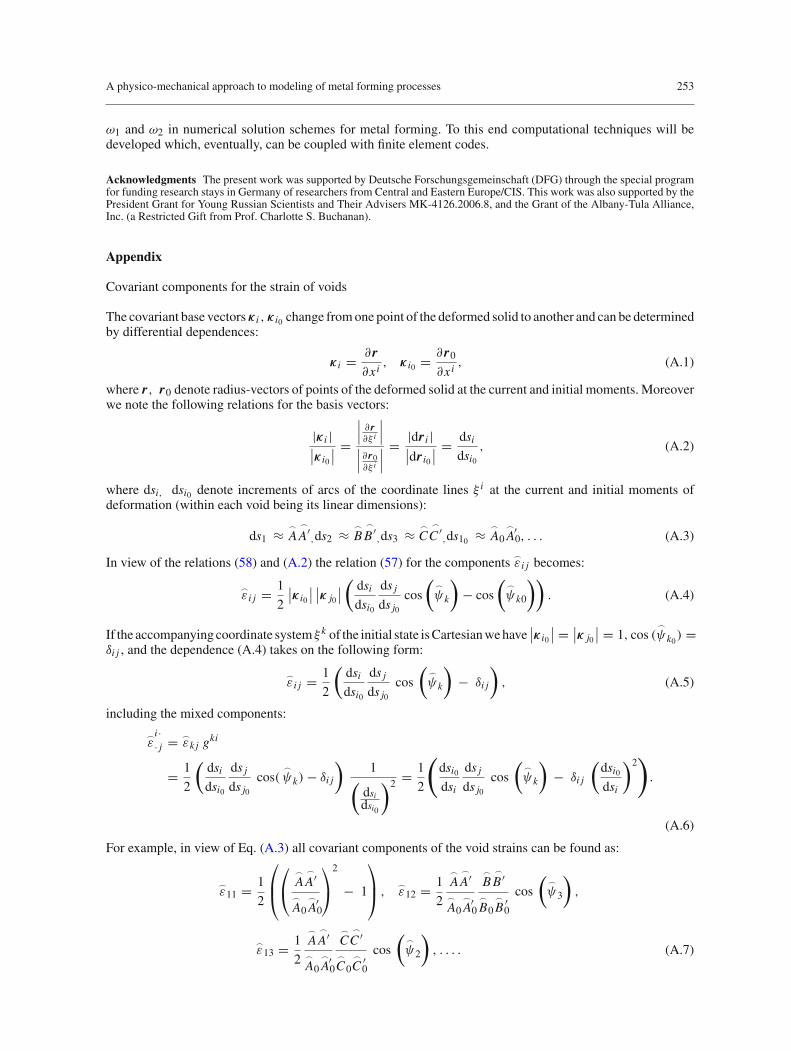
Covariant components for the strain of voids
The covariant base vectors κ i , κ i0 change from one point of the deformed solid to another and can be determinedby differential dependences:
κ i = ∂ r∂xi
, κ i0 = ∂ r0
∂xi, (A.1)
where r, r0 denote radius-vectors of points of the deformed solid at the current and initial moments. Moreoverwe note the following relations for the basis vectors:
|κ i |∣∣κ i0
∣∣ =∣∣∣ ∂ r∂ξ i
∣∣∣∣∣∣ ∂ r0∂ξ i
∣∣∣= |dr i |∣∣dr i0
∣∣ = dsi
dsi0
, (A.2)
where dsi, dsi0 denote increments of arcs of the coordinate lines ξ i at the current and initial moments ofdeformation (within each void being its linear dimensions):
ds1 ≈
A
A′,ds2 ≈
B
B ′,ds3 ≈
C
C ′,ds10 ≈
A0
A0′, . . . (A.3)
In view of the relations (58) and (A.2) the relation (57) for the components ε i j becomes:
ε i j = 1
2
∣∣κ i0
∣∣ ∣∣κ j0
∣∣(
dsi
dsi0
ds j
ds j0cos
(
ψk
)− cos
(
ψk0
)). (A.4)
If the accompanying coordinate system ξ k of the initial state is Cartesian we have∣∣κ i0
∣∣ = ∣∣κ j0
∣∣ = 1, cos (
ψk0) =
δi j , and the dependence (A.4) takes on the following form:
ε i j = 1
2
(dsi
dsi0
ds j
ds j0cos
(
ψk
)− δi j
), (A.5)
including the mixed components:
ε
i ·· j =
εk j gki
= 1
2
(dsi
dsi0
ds j
ds j0cos(
ψk)− δi j
)1(
dsidsi0
)2 = 1
2
(dsi0
dsi
ds j
ds j0cos
(
ψk
)− δi j
(dsi0
dsi
)2).
(A.6)
For example, in view of Eq. (A.3) all covariant components of the void strains can be found as:
ε11 = 1
2
⎛⎜⎝
⎛⎝
A
A′
A0
A0′
⎞⎠
2
− 1
⎞⎟⎠ ,
ε12 = 1
2
A
A′
A0
A0′
B
B ′
B0
B0′
cos
(
ψ3
),
ε13 = 1
2
A
A′
A0
A0′
C
C ′
C0
C0′
cos
(
ψ2
), . . . . (A.7)

254 M. A. Zapara et al.
References
1. Armero, F., Oller, S.: A general framework for continuum damage models. I. Infinitesimal plastic damage models in stressspace. Int. J. Solids Struct. 37, 7409–7436 (2000)
2. Bernstein, M.L.: Micro-structure of Deformed Metals. Metallurgy, Moscow (1977) (in Russian)3. Bogatov, A.A., Mizhiritskiy, O.I., Smirnov, S.V.: Resource of Metals Plasticity during Forming. Metallurgy, Moscow (1984)
(in Russian)4. Briottet, L., Klöcker, H., Montheillet, F.: Damage in a viscoplastic material. Part II. Overall behaviour. Int. J. Plast. 14, 453–
471 (1998)5. Brunig, M.: An anisotropic ductile damage model based on irreversible thermodynamics. Int. J. Plast. 19, 1679–1713 (2003)6. Butuc, M.C., Gracio, J.J., Baratada Rocha, A.: An experimental and theoretical analysis on the application of stress-based
forming limit criterion. Int. J. Mech. Sci. 48, 414–429 (2006)7. Chen, B., Li, W.G., Peng, X.H.: A microvoid evolution law involving change of void shape and micro/macroscopic analysis
for damaged materials. J. Mater. Process. Technol. 122, 189–195 (2002)8. Demir, I., Zbib, H.M.: A mesoscopic model for inelastic deformation and damage. Int. J. Eng. Sci. 39, 1597–1615 (2001)9. Dung, N.L.: Plasticity theory of ductile fracture by void growth and coalescence. Forsch. Ingenieurw. 58, 135–140 (1992)
10. Fan, J., Zhang, J.: An endochronic constitutive equation for damaged materials. Chin. Sci. (Ser. A) 32, 246–256 (1989)11. Fleck, N.A., Hutchinson, J.W.: Void growth in shear. Proc. R. Soc. Lond. Ser. A 407, 435–458 (1986)12. Gelin, J.C.: Modelling of damage in metal forming processes. J. Mater. Process. Technol. 80–81, 24–32 (1998)13. Glazoff, M.V., Barlat, F., Weiland, H.: Continuum physics of phase and defect microstructures: bridging the gap between
physical metallurgy and plasticity of aluminum alloys. Int. J. Plast. 20, 363–402 (2004)14. Gurson, L.: Continuum theory of ductile rupture by void nucleation and growth. J. Eng. Mater. Technol. Trans. ASME 99,
2–15 (1977)15. Hill, R.: The mathematical theory of plasticity. Clarendon Press, Oxford (1983)16. Horstemeyer, M.F., Matalanis, M.M., Sieber, A.M., Botos, M.L.: Micromechanical finite element calculations of temperature
and void configuration effects on void growth and coalescence. Int. J. Plast. 16, 979–1015 (2000)17. Il’iushin, A.A.: Plasticity: Fundamentals of the General Mathematical Theory. Nauka, Moscow (1963) (in Russian)18. Kachanov, L.M.: Introduction to Continuum Damage Mechanics. Kluewer, Dordrecht (1986)19. Khraishi, T.A., Khaleel, M.A., Zbib, H.M.: A parametric-experimental study of void growth in superplastic deformation
Int. J. Plast. 17, 297–315 (2001)20. Klöcker, H., Tvergaard, V.: Growth and coalescence of non-spherical voids in metals deformed at elevated temperature. Int.
J. Mech. Sci. 45, 1283–1308 (2003)21. Kolmogorov, V.L., Bogatov, A.A., Migachev, B.A.: Plasticity and Fracture. Metallurgy, Moscow (1977) (in Russian)22. Korn, G.A., Korn, T.M.: Mathematical Handbook for Scientists and Engineers: Definitions, Theorems, and Formulas for
Reference and Review. 2nd revised edn. Dover Publications, New York (2000)23. Krajcinovic, D.: Damage mechanics: accomplishments, trends and needs. Int. J. Solids Struct. 37, 267–277 (2000)24. Lemaitre, J., Desmorat, R., Sauzay, M.: Anisotropic damage law of evolution. Eur. J. Mech. A/Solids 19, 187–208 (2000)25. Maire, E., Bordreuil, C., Babout, L., Boyer, J.-C.: Damage initiation and growth in metals. Comparison between modelling
and tomography experiments. J. Mech. Phys. Solids 53, 2411–2434 (2005)26. Makarov, E.S., Tutyshkin, N.D., Gvozdev, A.E., Tregubov, V.I., Zapara, M.A.: Technological Mechanics of Dilating Mate-
rials. 3rd rev. and add. edn. Tul’skiy Polygraphist Publ., Tula (2007) (in Russian)27. McClintock, F.A.: A criterion for ductile fracture by the growth of holes. J. Appl. Mech. 90, 363–371 (1968)28. Menzel, A., Steinmann, P.: A theoretical and computational framework for anisotropic continuum damage mechanics at
large strains. Int. J. Solids Struct. 38, 9505–9523 (2001)29. Panin, V.E.: Physical Mesomechanics of Heterogeneous Media and Computer-Aided Design of Materials. Cambridge
Publishing, Cambridge (1998)30. Pirondi, A., Bonora, N., Steglich, D., Brocks, W., Hellmann, D.: Simulation of failure under cyclic plastic loading by damage
models. Int. J. Plast. 22, 2146–2170 (2006)31. Rice, J., Tracey, D.: On ductile enlargement of voids in triaxial stress field. J. Mech. Phys. Solids 17, 201–217 (1969)32. Sedov, L.I.: Continuum Mechanics, vol. 1. Nauka, Moscow (1983) (in Russian)33. Tang, C.Y., Shen, W., Lee, T.C.: A damage-based criterion for fracture prediction in metal forming processes: a case study
in Al 2024T3 sheet. J. Mater. Process. Technol. 89–90, 79–83 (1999)34. Thomson, C.I.A., Worswick, M.J., Pilkey, A.K., Lloyd, D.J.: Void coalescence within periodic clusters of particles. J. Mech.
Phys. Solids 51, 127–146 (2003)35. Tutyshkin, N.D., Zapara, M.A.: The advanced method of definition of stress and velocity fields in the processes of axisym-
metric plastic yielding. In: WSEAS Trans. on Heat and Mass Transfer vol. 2, pp. 150–15636. Tutyshkin, N.D., Gvozdev, A.E., Tregubov, V.I.: Complex Problems of Plasticity Theory. Tul’skiy Polygraphist Publ., Tula
(2001) (in Russian)37. Voyiadjis, G.Z., Venson, A.R., Kattan, P.I.: Experimental determination of damage parameters in uniaxially-loaded metal-
matrix composites using the overall approach. Int. J. Plast. 11, 895–926 (1995)38. Weinberg, K., Mota, A., Ortiz, M.: A variational constitutive model for porous metal plasticity. Int. J. Comput. Mech. 37,
142–152 (2006)39. Xiang, Y., Wu, S.: Numerical simulation of cavity damage evolution in superplastic bulging process. J. Mater. Process.
Technol. 116, 224–230 (2001)40. Yokobori, T.: An Interdisciplinary Approach to Fracture and Strength of Solids. Wolters-Noordhoff Scientific Publications
Ltd., Groningen (1966)41. Zaikov, M.A.: Strength of carbon steels at high temperatures. J. Tech. Phys. 19, 684–695 (1949) (in Russian)42. Zhu, M., Jin, Q.L.: A constitutive relation for materials containing voids and application in closing of voids. In: Fan, J.,
Murakami, S. (eds.) Proceedings of the ICCLEM, Chongqing, pp. 542–545 (1989)