Embed Size (px)
Citation preview

A physical model study on site condition effect on
seismic performance of storage tanks
Ali Shafaat1 and Abbas Ghaladarzadeh2 1Zachary Department of Engineering, Texas A&M University, Texas, US
2Civil Engineering Department, University of Tehran, Tehran, Iran
ABSTRACT:
Liquid Storage tanks are common and very important structures in industrial, commercial and lifeline sites. Because of their key function in industry and the importance of the liquids they contain; several studies have been conducted on the dynamic behavior of these thin shell structures. This study reports a series of shaking table tests carried out on precise-scaled models of a cylindrical flexible petrochemical liquid storage tank. These models were tested using a cylindrical laminated box. The experiments were repeated for different intensities of input motion. The results demonstrated that site conditions can considerably affect the seismic performance of these structures and their failure modes.
RÉSUMÉ Tanques de almacenamiento liquido son estructuras comunes y muy importantes en los sitios industriales, commerciales, y lineas de vida. Dado a su funccion clave en la industria y la importancia de los liquidos que contienen, varios estudios han sido conducidos en el comportamiento dinamico de estas estructuras de armazón delgado. El estudio consiste de un serie de experimentos con mesas que agitan modelos de precisa escala de un tanque flexible petroquimico de almacen cilindrical. Estos modelos fueron probados en una caja de lamina cilíndrica. Los experimentos fueron repetidos con diferentes intensidades de aporte de movimiento. Los resultados demostraron que las condiciones del sitio pueden afectar considerablemente el desempeño sísmico y modos de falla de estas estructuras. 1 INTRODUCTION Several numerical, experimental and field studies have been conducted to investigate the dynamic behavior of storage tanks during earthquakes (Zeiny 2000). Of these, the experimental studies are important but also the most expensive. Because of the increased cost, there are few experimental studies conducted on storage tanks, and in these studies, geotechnical issues are rarely considered. Modeling a large-scale geotechnical problem for a storage tank requires shaking at least 50 to 150 tons of soil with powerful actuators. Despite the small scale of our study, most of the expected failure modes were observed to be similar to those found in previous large scale studies (Iai 1997, Niwa 1979, Clough 1977).
Analysis of liquid storage systems includes three major items; modeling the liquid movement due to induction of ground motions, modeling the dynamic response of the structure due to the subsurface motion and the hydrodynamic pressure, and finally, modeling the soil behavior under the storage tank due to uplifting and settlement of the structure. Boundary interactions should be considered in the studies. Due to economical and technical consideration, large and medium sized storage tanks are often constructed unanchored. The unanchored tanks behave more intricately during earthquakes. In some cases the foundation is eliminated
and the tanks’ base plate is placed directly on the compacted ground instead. 1.1 Failure modes in storage tanks during earthquake Several damages occur during an earthquake on storage tanks (Rinne 1967; Jenning 1971; Leeds 1979; Shih & Babcock 1984). The critical ones are as follows: 1.1.1 Elephant foot buckling Elephant foot buckling is a heave near the ground. This failure mode occurs often in tanks with a low height to radius ratio (<1.5) (Dongh 2007). 1.1.2 Diamond shape buckling The mode of failure is a result of high vertical pressure. Niwa & Clough (1979) considered the high vertical pressure as a result of the rocking motion. This kind of failure is highly influenced by imperfections in the tank fabrication. 1.1.3 Base uplifting due to rocking motion Both anchored and unanchored tanks can experience partial uplifting because of the overturning moment. This problem is more serious for unanchored tanks. (Taniguchi 2005; Zeiny 2000)
The uplifting may not cause failure itself but it can create serious problems for pipes and other connections

and adjacent facilities. The part of the storage tank shell which is in contact with these joints may tear. 1.1.4 Roof Damage Ground storage tanks depending on their content, have fixed or floating roofs. Fixed roofs generally have cone shapes which have been put on tubular shells. Sloshing waves produced by earthquakes can impact roofs. This may cause splitting and in some cases may cause fire or even explosion.
In this study we observed all failure modes except elephant foot buckling. Section two of this paper presents the approach of this study. It describes the modeling procedure, the implements, and test process conducted in the research. The third section explains the failure modes observed during tests. The forth section discusses data obtained from instrumentation, and the fifth section is dedicated to the results. 2 RESEARCH METHOD The research was done through shaking table model tests. A scaled model of a constructed storage tank was fabricated and subjected to dynamic cyclic motions and the performance was observed. The reliable quantitative and qualitative results were acquired. Due to budget, technical limits and the size of the actual model, which was one of the largest storage tanks in the region, the maximum scale implemented was 1/100. The real structure, which has been modeled, is a storage tank with a 64 meter diameter and a 24 meter height. It is the largest liquid storage tank in southern Iran, which has been designed to contain polypropylene. 2.1 Similarity laws In the designing process of a flexible thin wall storage tank, bending is the governing factor (Malhotra 1997; Clough 1977). Therefore the following similarity equation was used for designing the tank (Iai 1989, 1997):
In which tp (cm), Ep (Mpa) are thickness and elasticity module of the structure and tm (cm), Em (Mpa) are thickness and elasticity module of the model. N is the scale factor, which is 100 in this model. The prototype structure has differential wall thickness; it is 38 mm at the bottom and reaches to 10 mm at the top in fifteen steps. The equation was solved for different materials but, since the scale factor was large, none of them were applicable. The only possible and available metal was phosphor-bronze. 2.2 Fabrication of the model tank As mentioned previously, there were two significant problems. The first one was the material. The selected material, inspite of the low thicknesses, had to resist the temperature of soldering. The second obstacle was the
joints. Different kinds of joints, including types of welding, were examined. The only practical method was soldering. But the problem still remained. The high temperature could melt the very thin sheets easily, so only a specialist could solder the joints. Table 1. Prototype versus model shell thicknesses (mm) Thickness of prototype Thickness of the model
12 0.007
23 0.014
30 0.018
38 0.022
Only two different useful thicknesses of phosphor
bronze were available in the market. Those were 0.1mm and 0.2 mm. Therefore, the model tank was built in two different thicknesses; the lower part in 0.2mm and the upper part in 0.1mm. The roof and bottom plates also
were 12mm in the prototype model, so they were both built in 0.1mm thicknesses. The tank was a cylindrical with 60cm diameter and 22cm height.
Figure 1. Instrumented model placed on the cylindrical storage laminated box 2.3 The laminated box In order to reduce the side effect of the rigid walls of the soil box, a cylindrical laminated box designed for the experiment. The box was built of aluminum rings which had been separated by rubber straps. The laminated box was designed for both dry and saturated tests therefore, a rubber diaphragm was used to prevent water run out. The diameter of the cylinder is 100 cm and the height is adjustable due to numbers of rings and rubber straps. All the components are shown in the Figure 1. As shown in Figure 1, there are four aluminum rings below the rubber diaphragm which has extended above rings. The modeled storage tank is resting on the soil. All six linear
cmNE
Ett
m
p
pm 022.0)100
1.
110
210(8.3)
1.( 3
1
5.35.3===

variable differential transformers (LVDT) identical sensors -two vertical and four horizontal- are attached according to the instrument map given in Figure 2. The whole system is mounted on the shaking table deck. 2.4 Phosphor bronze Phosphor bronze is an alloy of copper with 3.5 to 10% of tin and a significant phosphorus content of up to 1%. The phosphorus is added as a deoxidizing agent during melting. These alloys are notable for their toughness, strength, low coefficient of friction, and fine grain. The phosphorus also improves the fluidity of the molten metal and thereby improves the castability and mechanical properties by cleaning up the grain boundaries. Furthermore, increasing the phosphorus content leads to formation of a very hard compound Cu3P (copper phosphide), resulting in a brittle form of phosphor bronze, which has a narrow range of applications. The mechanical properties of phosphor bronze are shown in table
Figure 2. Instrumentation maps
2.4 Conducted Tests The model tanks were subjected to two different frequencies with different accelerations sinusoidal motion. The base soil is poor graded sand (SP) with maximum grain size of 4mm. The laminar box was filled with sand without any compaction. Table 2. Phosphor Bronze mechanical properties Property Unit Value
Hardness Rockwell B Scale 78
Tensile Strength MPa 482
Yield Strength MPa 400
Elongation(rod) % in 5cm 25
Modulus od Elasticity MPa 110,000
According to studies, liquid in the tank has two different movements with two different frequency levels. The impulsive movement is in the lower part of the tank and causes rocking movement and elephant buckling. Sloshing movement is on the upper part of the liquid body. The diamond shape buckling and roof damage are results of this movement (Haroun 1981). Both of the movements were experienced in our tests. Different accelerations (0.1g to 0.6g) were tested and soil structure and liquid behavior were studied. Tables 3 and 4 list the experiments which were carried out:
Table 3. Experiments on the first tank
Test No. Acceleration Frequency Relative Soil Density
1 0.1g 3HZ 0.678
2 0.2g 3HZ 0.678
3 0.3g 3HZ 0.678
4 0.4g 3HZ 0.678
5 0.5g 3HZ 0.678
6 0.6g 3HZ 0.678
Table 4. Experiments on the second tank
Test No. Acceleration Frequency Relative Soil Density
1 0.1g 5HZ 0.678
2 0.2g 5HZ 0.678
3 0.3g 5HZ 0.678
4 0.4g 5HZ 0.678
5 0.5g 5HZ 0.678
6 0.6g 5HZ 0.678
3 OBSERVED DAMAGES 3.1 First Experiment For acceleration 0.1g to 0.2g no damage was observed. In the 0.3g acceleration, a slight slip occurred. In the 0.4g, diamond shape buckling was seen and repairing was required. In the fifth one (0.5g), the bulking spread on the wall of the tank. In the max acceleration (0.6g), diamond shape buckling established in which the storage tank needed serious repair. In Figure 3, the diamond shape damage is shown on the model tank which is on the laminated box.
3.2 Second Experiment No damage was observed in either the first or the second acceleration. In the third acceleration (0.3g), slight slip occurred. In the fourth acceleration, both diamond shape buckling and differential settlement happened. The fifth experiment made the settlement worse. The last acceleration caused significant settlement and spread
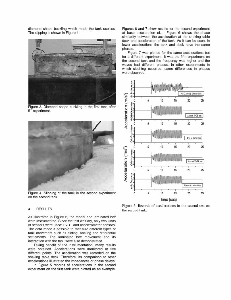
diamond shape buckling which made the tank useless. The slipping is shown in Figure 4.
Figure 3. Diamond shape buckling in the first tank after 5th experiment.
Figure 4. Slipping of the tank in the second experiment on the second tank.
4 RESULTS As illustrated in Figure 2, the model and laminated box were instrumented. Since the test was dry, only two kinds of sensors were used: LVDT and accelerometer sensors. The data made it possible to measure different types of tank movement such as sliding, rocking and differential settlements. The laminated box movement and its interaction with the tank were also demonstrated.
Taking benefit of the instrumentation, many results were obtained. Accelerations were monitored at five different points. The acceleration was recorded on the shaking table deck. Therefore, its comparison to other accelerations illustrated the impedances or phase delays.
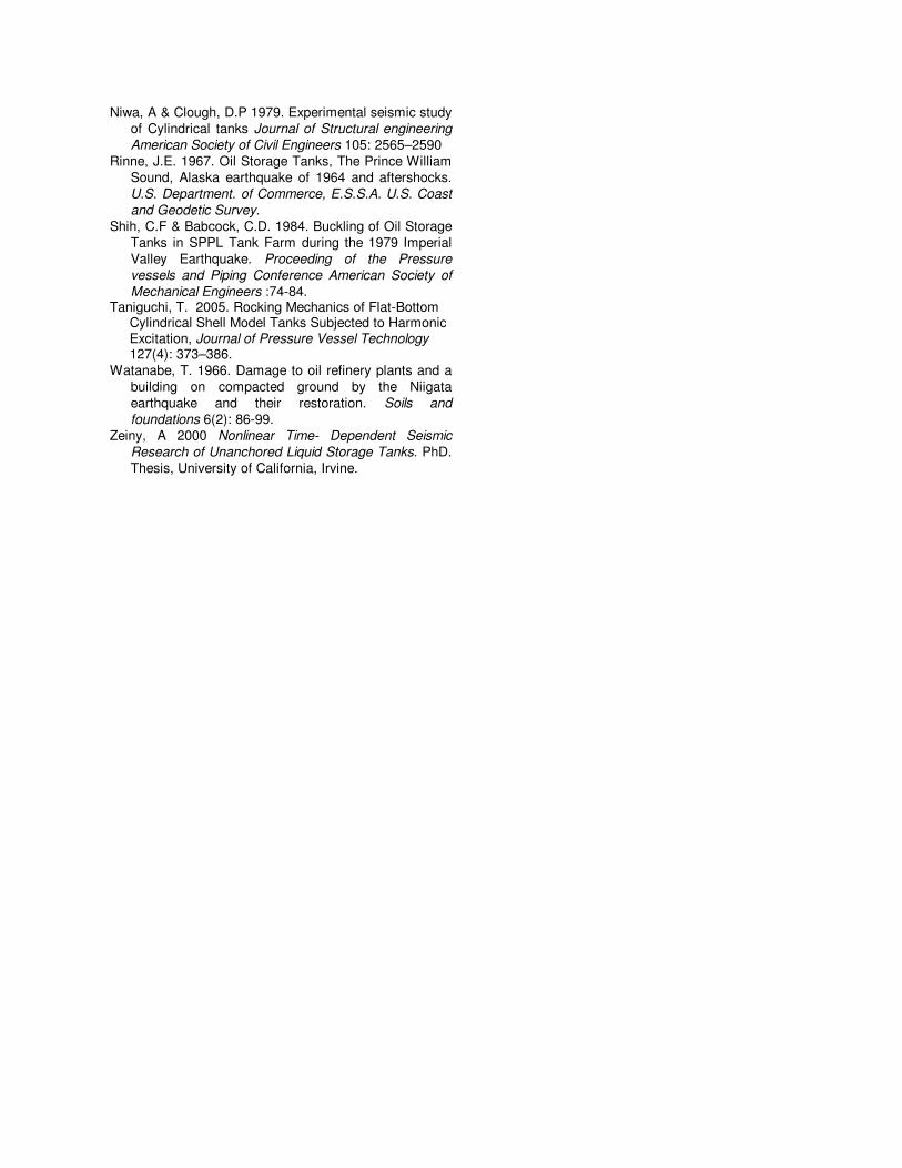
In Figure 5 records of accelerations in the second experiment on the first tank were plotted as an example.
Figures 6 and 7 show results for the second experiment at base acceleration of…. Figure 6 shows the phase similarity between the acceleration at the shaking table deck and acceleration of the tank. As it can be seen, in lower accelerations the tank and deck have the same phases.
Figure 7 was plotted for the same accelerations but for a different experiment. It was the fifth experiment on the second tank and the frequency was higher and the waves had different phases. In other experiments in which sloshing occurred, same differences in phases were observed.
Figure 5. Records of accelerations in the second test on
the second tank.

Figure 6. Acceleration at base versus acceleration on the tank in the second experiment on the second tank.
Figure 7. Acceleration at the base versus acceleration on the Tank in the fifth experiment on the second tank.
In Figure 8, the vertical displacements of the two sides of the tanks are shown. The differences at the ends show differential settlement. They also show the uplifting of the tank during induced ground movement. These large displacements which also occurred during the experiment at both sides can cause problems with the connected piping system. In addition, accumulation of water in one side of the tank intensifies the problem of residual displacement.
Figure 8. Vertical displacement versus time on the front of the tank (light line) and at the back of the tank (dark line) in the 5th experiment on the second tank.
In Figure 9, base acceleration against horizontal displacement of the tank is plotted. In lower accelerations the responses had the same phases, however in the higher accelerations, as can be seen in Figure 9, there were some phase lags. The results also show some tank slippage, as was previously shown in Figure 4. In higher accelerations a combination of slipping and differential settlement caused foundation problems.
Figure 9. Base acceleration versus the tank horizontal
displacement in the fourth experiment on the second tank.
Both sloshing and impulsive movements of water
have low frequencies. It has been shown in Figure 10 that there are two peaks, one for the induced movement around 3 Hz and another one around 1 Hz because of water movement. The Fourier spectrum has been plotted for the data which was produced in the fifth experiment on the first tank with the frequency of 3 Hz. There are two distinguished peaks which approximately happen at the frequencies of 3 Hz and 1 Hz. It would appear that the second peak is due to the water movement in the tank.
The Fourier spectrum has been plotted for the data which was produced in the fifth experiment on the first tank with the frequency of 3 Hz. There are two distinguished peaks which approximately happen at the frequencies of 3 Hz and 1 Hz. It would appear that the second peak is due to the water movement in the tank.
(Sec)
(cm
)

Figure 10. Fourier spectrum for forth experiment on the first tank.
All monitored settlements and slippages are shown in
Figure 11 for the fourth experiment on the first tank with 0.4g acceleration. Both slipping and the differential settlement can be seen in this figure.
Figure 11. Horizontal and Vertical Displacements of
the tank during the fourth experiment on the first tank.
5 CONCLUSIONS Diamond shape buckling was observed in both experiments at accelerations 5 and 6 Hz. The failure was worse in the first experiment; we believe that it was because of the lower frequency of the sloshing waves which may cause some kind of resonances with the 3 Hz frequency of the induced motion (Malhotra 2005).
Rocking motions which were observed in the model tests were similar to what had been reported before in real earth-quakes; but due to absence of connections and pipes - which can somehow limit the tank’s movement - it occurred more severely in the experiment (D'Orazion & Dancan 1989).
Although there is no formal report about inadequate improved soil under the tanks, photos presented from Alaska (1964) (Rinne, 1967) and Niigata (1966)
(Watanbe, 1966) and observations from these tests indicated that earthquake response behavior is similar to results observed in our tests.
Analysis indicated that as shells have no resonance, as expected. It is because of their higher natural frequencies (Malhotra 2005).
Elephant foot buckling did not occur in these tests. The thicker plates at the lower level of the shell prevented this failure mode from occurring.
The material selection for fabrication of the model was successful but in larger model test we suggest steel sheets rather than Phosphor bronze because working with phosphor bronze thin sheets is hard and needs extremely caution.
6 REFERENCES Bagheri S. 2001. Analysis of Seismic Behavior of
flexible on ground Storage Tanks. MSc, Thesis Sharief University.
Clough D.P. 1977 Experimental Evaluation of seismic Design Method for Broad Cylindrical Tanks. Earthquake Engineering Research Center Report, UCB/EERC 77-10.
Dong, Y. & Redekop, D. 2007 Structural and Vibrational Analysis of Liquid Storage Tanks, SMiRT 19 conference, Toronto, Paper # B07/5.
D'Orazion T.B. & Dancan J.M. 1989 Differential Settlements in Steel Tanks. Journal of Geotechnical
Engineering- American Society of Civil Engineers 115(7): 1035-1036.
Haroun, M.A. & Housner, G.W. 1981. Seismic design of liquid storage tanks. Journal of the Mechanical
Councils American Society of Civil Engineers 107(1): 191-207.
Iai, S. 1989. Similitude for Shaking Table Tests on Soil Structure-Fluid Model in 1g Gravitational Field. Soils
and Foundations, Japanese Society of Soil Mechanics
and Foundation Engineering 29(1):105-118. Iai, S. 1997. One Gravity Model Testing (discussion),
Soils and Foundations, Japanese Society of Soil
Mechanics and Foundation Engineering 37(1):137-138.
Jenning, P.C. 1971. Engineering Features of the San
Fernando Earthquake. California Institute of Technology, EERL 71-02.
Leeds, D.J. & Brandow G. 1979. Reconnaissance Report, Imperial County, California earthquake, Earthquake Engineering Research Institute, October 15, 1979.
Malhotra, P.K. 2005. Sloshing Loads in Liquid-Storage Tanks with Insufficient Freeboard, Earthquake
Spectra 21(4): 1185-1192 Malhotra, P.K. 1997. Seismic Response of soil-
supported unanchored liquid- storage tanks Journal
of Structural engineering. American Society of Civil
Engineers 123(4):440-450
Niwa, A & Clough, D.P 1979. Experimental seismic study of Cylindrical tanks Journal of Structural engineering
American Society of Civil Engineers 105: 2565–2590 Rinne, J.E. 1967. Oil Storage Tanks, The Prince William
Sound, Alaska earthquake of 1964 and aftershocks. U.S. Department. of Commerce, E.S.S.A. U.S. Coast
and Geodetic Survey. Shih, C.F & Babcock, C.D. 1984. Buckling of Oil Storage
Tanks in SPPL Tank Farm during the 1979 Imperial Valley Earthquake. Proceeding of the Pressure
vessels and Piping Conference American Society of
Mechanical Engineers :74-84. Taniguchi, T. 2005. Rocking Mechanics of Flat-Bottom
Cylindrical Shell Model Tanks Subjected to Harmonic Excitation, Journal of Pressure Vessel Technology 127(4): 373–386.
Watanabe, T. 1966. Damage to oil refinery plants and a building on compacted ground by the Niigata earthquake and their restoration. Soils and
foundations 6(2): 86-99. Zeiny, A 2000 Nonlinear Time- Dependent Seismic
Research of Unanchored Liquid Storage Tanks. PhD. Thesis, University of California, Irvine.