Embed Size (px)
Citation preview

N A S A T E C H N I C A L
R E P O R T N A S A TR R-223 " - -
c". /
A PERFECT-GAS ANALYSIS OF THE EXPANSION TUNNEL, A MODIFICATION TO THE EXPANSION TUBE
by Robert L. Trimpi und Linwood B. Callis
Lungley Reseurcb Center Lungley Stution, Humpton, Vu.
NATIONAL AERONAUTICS AND SPACE ADMINISTRATION WASHINGTON, D. C. APRIL 1 9 6 5
"JI
https://ntrs.nasa.gov/search.jsp?R=19650010885 2018-05-21T17:45:30+00:00Z

TECH LIBRARY KAFB, NM
00b8517
A PERFECT-GAS ANALYSIS O F THE EXPANSION TUNNEL,
A MODIFICATION TO THE EXPANSION TUBE
By Robert L. Trimpi and Linwood B. C a l l i s
Lang ley Resea rch Cen te r Langley Station, Hampton, Va.
NATIONAL AERONAUTICS AND SPACE ADMINISTRATION
" ~~
For sale by the Office of Technical Services, Department of Commerce, Woshington, D.C. 20230 -- Prico $4.00

CONTENTS
Page
SUMMARY . . . . . . . . . . . . . . . . . . . . . . . . . . . . . . . . . 1 INTRODUCTION . . . . . . . . . . . . . . . . . . . . . . . . . . . . . . 1 SYMBOLS . . . . . . . . . . . . . . . . . . . . . . . . . . . . . . . . . 2 THEORY . . . . . . . . . . . . . . . . . . . . . . . . . . . . . . . . . 5
Test-Gas Processes . . . . . . . . . . . . . . . . . . . . . . . . . . 5 Accelerating-Gas Processes . . . . . . . . . . . . . . . . . . . . . . 10 Dump-Tank Processes . . . . . . . . . . . . . . . . . . . . . . . . . . 11 Driver-Gas Processes . . . . . . . . . . . . . . . . . . . . . . . . . 16
LENGTHS O F COMPONENT SECTIONS AND TESTING TIMES . . . . . . . . . . . . . 18 Accelerating Chamber . . . . . . . . . . . . . . . . . . . . . . . . . 18 Nozzle . . . . . . . . . . . . . . . . . . . . . . . . . . . . . . . . 19 Intermediate Chamber . . . . . . . . . . . . . . . . . . . . . . . . . 25 Dump-Tank Length . . . . . . . . . . . . . . . . . . . . . . . . . . . 25 Driver-Chamber Length . . . . . . . . . . . . . . . . . . . . . . . . . 26
Diaphragm Bursting . . . . . . . . . . . . . . . . . . . . . . . . . . 27 Secondary diaphragm . . . . . . . . . . . . . . . . . . . . . . . . . 27 Primary diaphragm . . . . . . . . . . . . . . . . . . . . . . . . . . 29 Ter t i a ry diaphragm . . . . . . . . . . . . . . . . . . . . . . . . . 30
Driver Analysis . . . . . . . . . . . . . . . . . . . . . . . . . . . . 30 Eff ic iency . . . . . . . . . . . . . . . . . . . . . . . . . . . . . . 31 Viscous Effects . . . . . . . . . . . . . . . . . . . . . . . . . . . . 32 LOW Vacuum Considerations . . . . . . . . . . . . . . . . . . . . . . . 34
Accelerating chamber . . . . . . . . . . . . . . . . . . . . . . . . 34 Dumptank . . . . . . . . . . . . . . . . . . . . . . . . . . . . . . 34
Ef fec t of Nozzle Configurations . . . . . . . . . . . . . . . . . . . . 35 G e n e r a l e f f e c t . . . . . . . . . . . . . . . . . . . . . . . . . . . 35 Geometric and f l u i d mechanic parameters . . . . . . . . . . . . . . . 35
Example . . . . . . . . . . . . . . . . . . . . . . . . . . . . . . . . 40 Des ignDe ta i l s . . . . . . . . . . . . . . . . . . . . . . . . . . . . 42 C r i t i c a l Lengths . . . . . . . . . . . . . . . . . . . . . . . . . . . 42
Accelerating-chamber c r i t i c a l l e n g t h . . . . . . . . . . . . . . . . 42 Dynp-tank length . . . . . . . . . . . . . . . . . . . . . . . . . . 43
WERENCES . . . . . . . . . . . . . . . . . . . . . . . . . . . . . . . 46 TABLES . . . . . . . . . . . . . . . . . . . . . . . . . . . . . . . . . FIGURES . . . . . . . . . . . . . . . . . . . . . . . . . . . . . . . . . 49
DISCUSSION . . . . . . . . . . . . . . . . . . . . . . . . . . . . . . . 27
& S W . . . . . . . . . . . . . . . . . . . . . . . . . . . . . . . . . 44
47
iii
A PERFECT-GAS ANALYSIS OF THE EXPANSION TUNNEL,
A MODIFICATION TO THE EXPANSION TUBE
By Robert L. Trimpi and Linwood B . Callis Langley Research Center
SUMMARY
A perfect-gas analysis i s presented for an apparatus consisting of a bas i c expansion tube a t the downstream end of which a nozzle has been added. The resul tant apparatus , named the expansion tunnel, i s shown t o have the following advantages when compared with the basic expansion tube: increased tes t ing t ime, larger i n i t i a l t es t -gas s lug length , h igher e f f ic iency , and reduced secondary-diaphragm bursting problems. Principal disadvantages are require- ment of an addi t ional nozzle , and the requirement of a l a r g e r r a t i o between maximum and minimum pressures i n an operating cycle. Authors conclude inherent advantages more than compensate for disadvantages.
INTRODUCTION
For the pas t few y e a r s s c i e n t i s t s a t the Langley Research Center have been invest igat ing var ious modif icat ions to the basic expansion tube descr ibed i n reference 1. Effort has been concentrated on those var ia t ions which were more d i r e c t l y aimed a t a l l e v i a t i o n of the ant ic ipated pr incipal undesirable features of the expansion tube; namely, t h e s h o r t i n i t i a l l e n g t h of the t es t -gas s lug before diaphragm rupture, the bursting of the secondary diaphragm, and the s h o r t t e s t time. Both experimental and theo re t i ca l i nves t iga t ions have been conducted, and the l a t te r inc lude cons idera t ions o f severa l modi f ica t ions for bo th r ea l and per fec t gases . Most of the exper imenta l resu l t s ob ta ined to da te i n the pilot expansion tube at the Lsngley Research Center (unpublished) are for expansion-tube operation; these results appear encouraging.
This report w i l l descr ibe the perfect-gas analysis of the configurat ion tha t the au thors be l ieve ho lds the most promise for reducing the aforementioned drawbacks. This configuration, mentioned i n references 1 and 2, i s cal led an expansion tunnel and cons is t s o f a basic expansion tube to which a t t h e down- stream end a nozzle has been added. (See f i g . 1.) Thus t h e t e s t f l u i d i s processed first by an unsteady expansion in the accelerating chamber and then by a s teady expansion in the nozzle . A group a t t h e Von Karman Laboratory of t h e Arnold Engineering Development Center has a lso been inves t iga t ing bo th t h e o r e t i c a l l y and experimentally a d i f fe ren t conf igura t ion which has a nozzle located just after the secondary diaphragm. For such a conf igura t ion the f lu id
is processed first by a steady expansion and subsequently by an unsteady expan- sion if the accelerating chamber is several orders of magnitude longer than the nozzle. If these length restrictions are not satisfied, the test gas is proc- essed simultaneously by both steady and unsteady expansion waves with the result that the gas state at the test section continually varies with time. The relative prior occurrence of the unsteady expansion as compared with the steady expansion has an extremely important bearing on the subsequent charac- teristics of the apparatus. Consequently, even though both modifications contain nozzles, their operation and performances are very different.
The analysis herein is restricted to the perfect-gas assumption which per- mits the pertinent equations to be expressed in closed form. Such equations are valuable since important trends and influences can often be simply extracted and examined critically. A somewhat parallel real-gas analysis (unpublished to date) has also been executed. The rea.1-gas analysis verifies the perfect-gas trends of this paper although the magnitudes of the variations naturally are not identical.
For the convenience of the reader an index to the figures is presented as table I.
A
- Ageom
a
CV
D
d
d'
E
E -
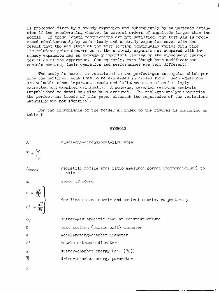
SYMBOLS
quasi-one-dimensional-flow area
geometric nozzle area ratio measured normal (perpendicular) to axis
speed of sound
) for linear area nozzle and conical nozzle, respectively
driver-gas specific heat at constant volume
test-section (nozzle exit) diameter
accelerating-chamber diameter
nozzle entrance diameter
driver-chamber energy (eq. (72) ) driver-chamber energy parameter
2
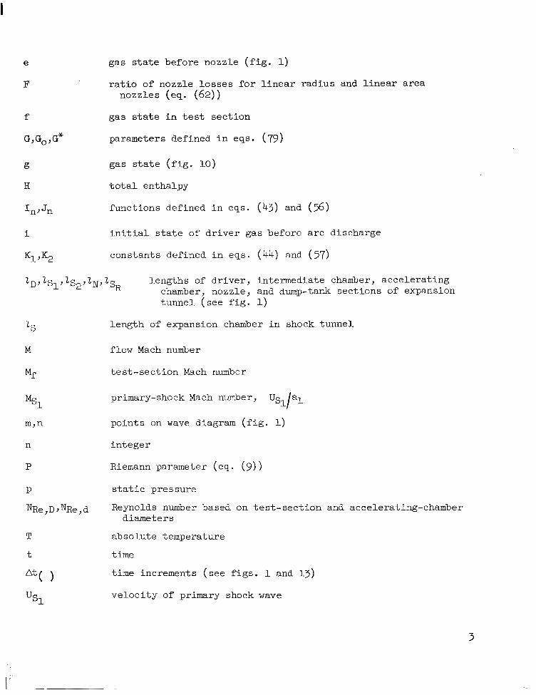
e gas state before nozzle ( f ig . 1)
F r a t i o of nozz le l o s ses fo r l i nea r r ad ius and l i n e a r a r e a nozzles (eq. (62))
f g a s s t a t e i n tes t sec t ion
G,G,,G* parameters defined i n eqs. (79)
g a s s t a t e ( f i g . 10)
t o t a l en tha lpy
I n J Jn funct ions def ined in eqs . (43) and ( 5 6 )
i i n i t i a l s t a t e of driver gas before arc discharge
K1 'K2 constants def ined in eqs . (44) and (37)
21)' is1 9 J IN, isR lengths of dr iver , in termediate chamber, acce le ra t ing chamber, nozzle, and dump-tank sec t ions of expansion tunne l ( s ee f i g . 1)
M
MS1
n
P
P
NRe,D,NRe,d
T
t
length of expansion chamber i n shock tunnel
flow Mach number
t e s t - sec t ion Mach number
primary-shock Mach number, Us,/al
po in ts on wave diagram ( f i g . 1)
i n t ege r
Riemann parameter (eq. ( 9 ) )
s t a t i c p re s su re
Reynolds number based on tes t -sect ion and accelerating-chamber diameters
absolute temperature
time
time increments (see figs. 1 and 13)
ve loc i ty of primary shock wave
3
I
%l
%o
usR
U
x
z
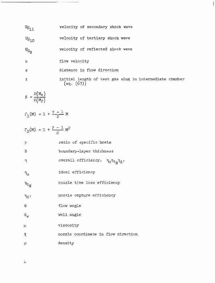
ve loc i ty of secondary shock wave
v e l o c i t y o f t e r t i a r y shock wave
ve loc i ty of r e f l e c t e d shock wave
flow velocity
d is tance i n f low direct ion
i n i t i a l l e n g t h of t e s t g a s slug in intermediate chamber (es. (67))
T1(M) = 1 + 2 M
r a t i o of s p e c i f i c h e a t s
boundary-layer thickness
ove ra l l e f f i c i ency , qoTzN7dt
70 i dea l e f f i c i ency
7 z N nozzle time loss e f f i c i ency
7d ' nozzle capture eff ic iency
e flow angle
OW wall angle
P v i s c o s i t y
5
P
nozzle coordinate in f low direction
dens i ty
4

R ( M ) = rl(M) p2(M)]-1'2
u) exponent in viscosi ty- temperature re la t ion
Additional remarks regarding notation:
0 ( )i subsc r ip t s ign i f i e s quan t i ty i s t o b e e v a l u a t e d i n i t h s t a t e
denotes gas i n s t a t e i in cyc le
( )ETun,( r e f e r s t o expansion tunnel, expansion tube, or nonreflected
( )NRs shock tunnel , respect ively
r e f e r s t o c r i t i c a l c o n d i t i o n s when Attest = 0 ( t h a t i s , nozzle t ime losses equal to ~ t 2 )
THEORY
A description of the expansion-tunnel components and operation i s more eas i ly expla ined wi th re fe rence to f igure 1 which shows a schematic of the tunnel and a distance-time or wave diagram of the operating cycle. The tunnel has f ive bas ic sec t ions : d r iver chamber, intermediate chamber, acce le ra t ing chamber, nozzle, and dump tank. Three diaphragms separate the f irst four pre- ceding sections. Thus, the expansion tunnel i s an expansion tube t o which has been added another diaphragm and a nozzle. The t e s t f l u i d , which i s i n i t i a l l y i n the intermediate chamber, i s processed f i r s t from s t a t e 0 t o s t a t e @ by the primary shock wave, n e x t t o t h e s t a t e @ by the unsteady upstream expan- s ion wave, and f i n a l l y t o t h e t e s t s t a t e @ by passage through the nozzle.
A perfect-gas theory i s developed t o i l l u s t r a t e t h e i m p o r t a n t f a c e t s of the expansion tunnel. The assumption of strong shock waves is used f o r a l l shock waves. Approximate equations a re a l so o f ten g iven in t e rms of t e s t - sec t ion Mach number and a rea r a t io fo r t he a sympto t i c l imi t ing ca ses of la rge nozz le ex i t and entrance Mach numbers. Each phase of the cycle i s t rea ted by consider ing in turn the processes of t h e g a s i n i t i a l l y i n t h e i n t e r m e d i a t e chamber, acce le ra t ing chamber, d r ive r chamber, and so f o r t h . Readers not i n t e r e s t e d i n details of the derivations, f low processes, and so f o r t h , can proceed t o t h e s e c t i o n on "Discussion" wherein the main points are considered
Test-Gas Processes
The tes t -gas processes are found by working backwards from the des i red tes t - sec t ion condi t ions @ through the intermediate states @ and @ t o t h e i n i t i a l c h a r g i n g state 0 . The test-gas value of y i s implied when 7 i s
5

used without a subscr ipt . All curves shown i n this repor t a r e fo r a t e s t g a s with y = 1.4.
The states @ and @ a re r e l a t ed by t h e familiar isentropic quasi-one- dimensional steady-flow equations (see ref. 3 ) :
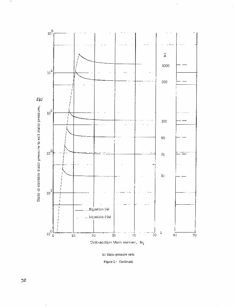
The var ia t ion wi th t es t - sec t ion Mach number Mf of the nondimensional
parameters on the left-hand side of equations (1) t o ( 4 ) f o r t h e p e r f e c t t e s t gas ( y = 1 . 4 ) i s g iven i n f i gu res 2 (a ) t o 2 (d ) . The a r e a r a t i o x var ies from the basic expansion tube value of uni ty t o 1000. The curves are terminated by a short dashed line a t the lower Mach number end when the expansion fan has com- pletely vanished (Me = % = 1.89) and the apparatus i s then operat ing as a non- r e f l ec t ed shock tunnel . ( O f course, in a nonreflected tunnel one would t e s t i n g a s i n i t i a l l y i n t h e a c c e l e r a t i n g chamber ra ther chamber. )
The asymptotic approximations for equations
assuming Mf >> - and M, >> -. Then 2 2 2 2 Y - 1 Y - 1
2
and from equat ions (2) , (3), and (4)
than in the intermediate
(1) t o (4) are obtained by
from equation (1)
Y -1 2
a Mf (A) -
2%" af Me
6

Pe, (A)7 Pf
These approximations are indicated a t the higher values of Mf i n f i g -
ure 2. Note ( f i g . 2 ( b ) ) t h a t f o r Mf ,> 20, the exact values of 2 . 2 0.9;
therefore , only a small percentage increase in ve loc i ty occurs in the nozz le .
U
Uf
Since the process from @ + @ -+ @ i s simply the expansion tube process of reference 1, the equat ions of that reference are appl icable to the t e s t g a s by s u b s t i t u t i o n o f s t a t e @ f o r s t a t e 0. However, a b r i e f ou t l i ne
of the necessary steps i s as fol lows: The strong shock assumptions
r equ i r e t ha t
u 2 - J'" "
al Y ( Y + 1) P l
(Eqs. ( 5 ) t o (8) a r e i d e n t i c a l t o e q s . ( 3 ) t o (6) of . re f . 1. ) The value of I,$ i s approximately 1.89 f o r 7 = 1.4. The Riemann parameter P i s con- s tant across the upstream wave (eq. (7) of ref . 1); thus,
7

Consequently,
Combining equations (2) and (4) with equations (10) and (11) y ie lds
where
Other per t inent parameters in s ta te 0 are then
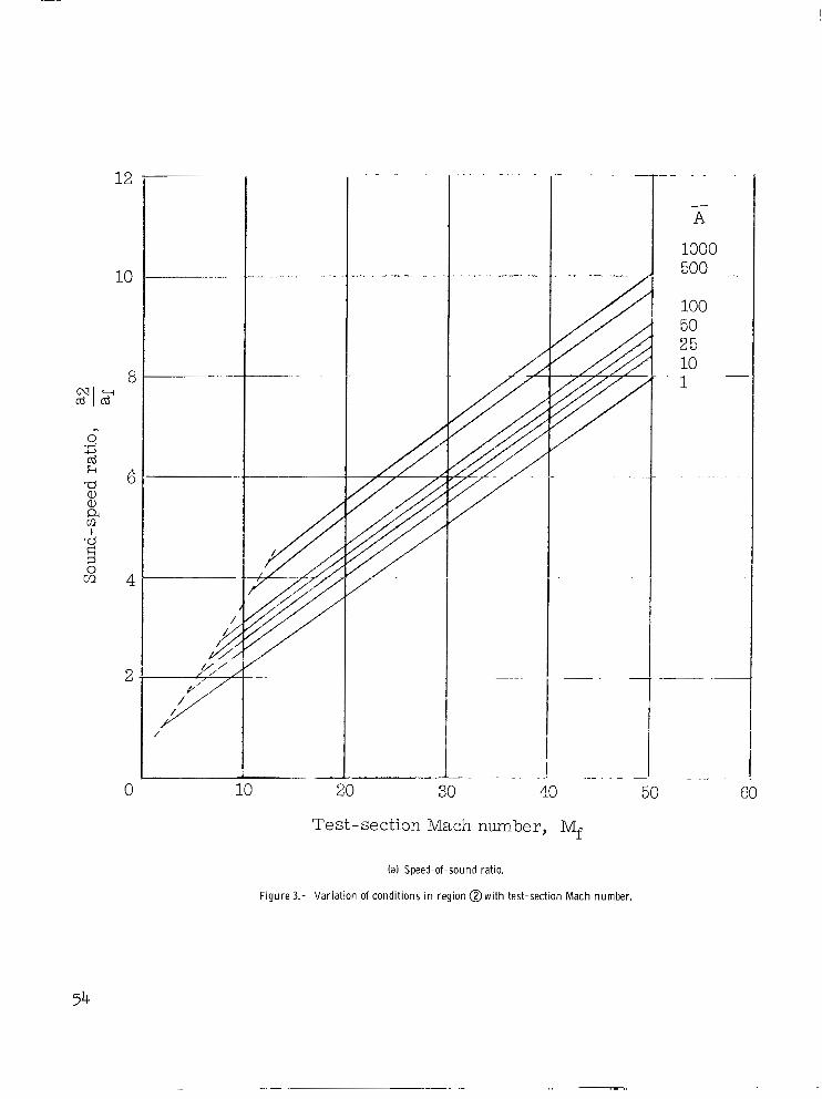
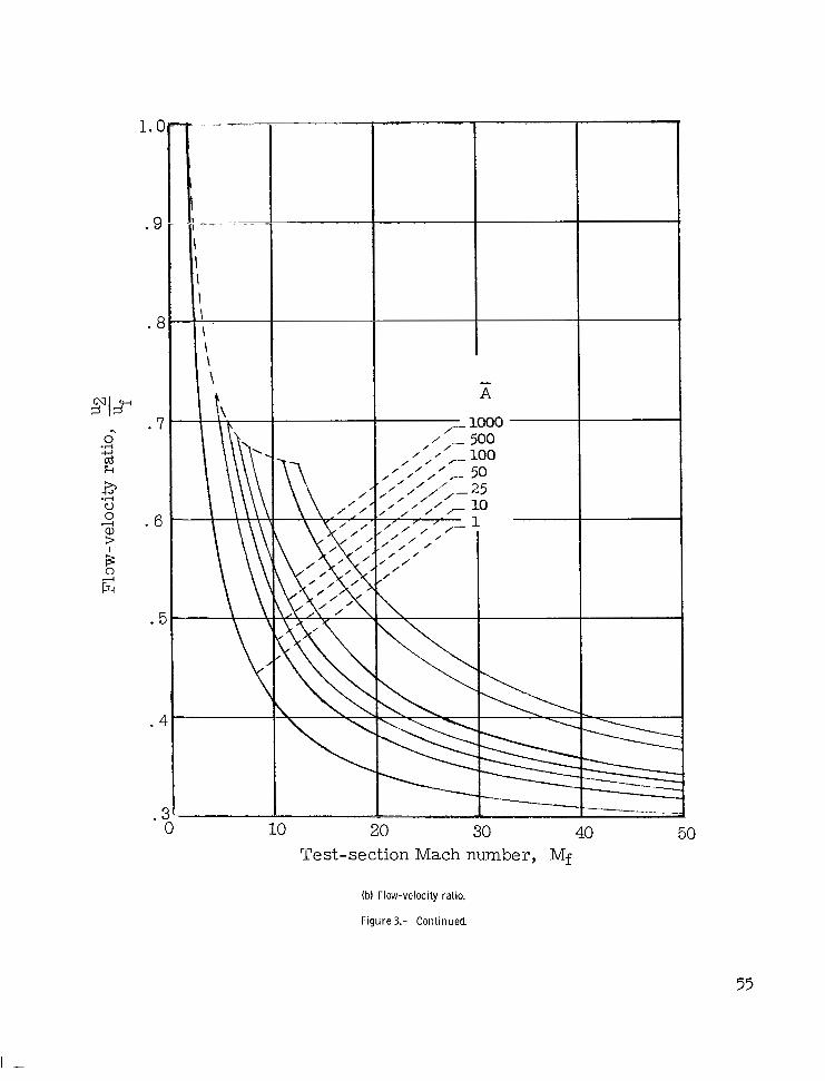
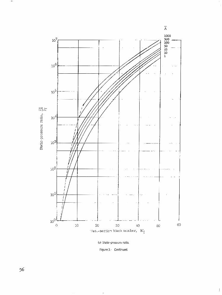
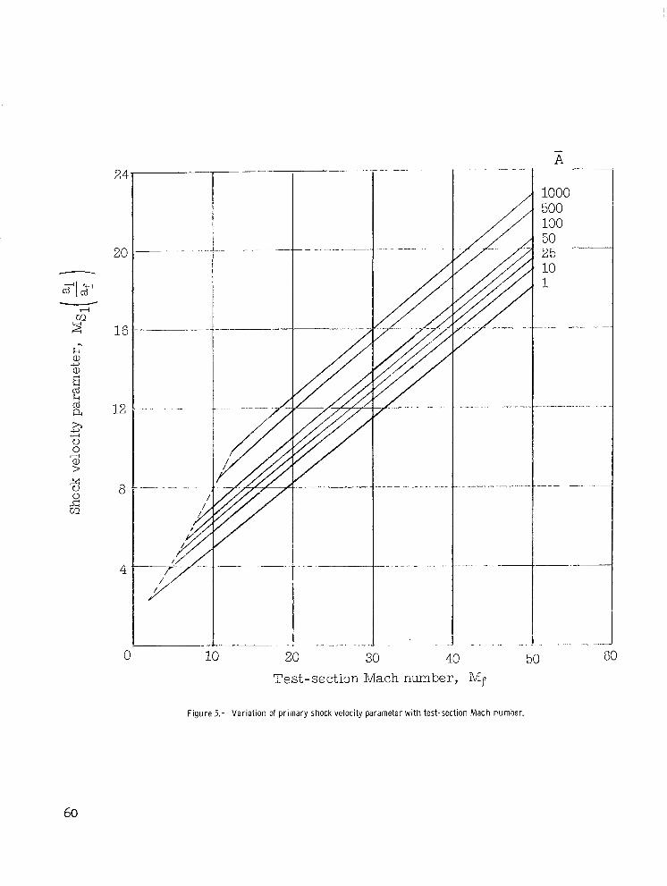
P l o t s of equations (12), (l3), (l?), and (16) appear in f igure 3. The values of a2, u2, p2, and H2 a l l are increased as A i s increased for a
-
8
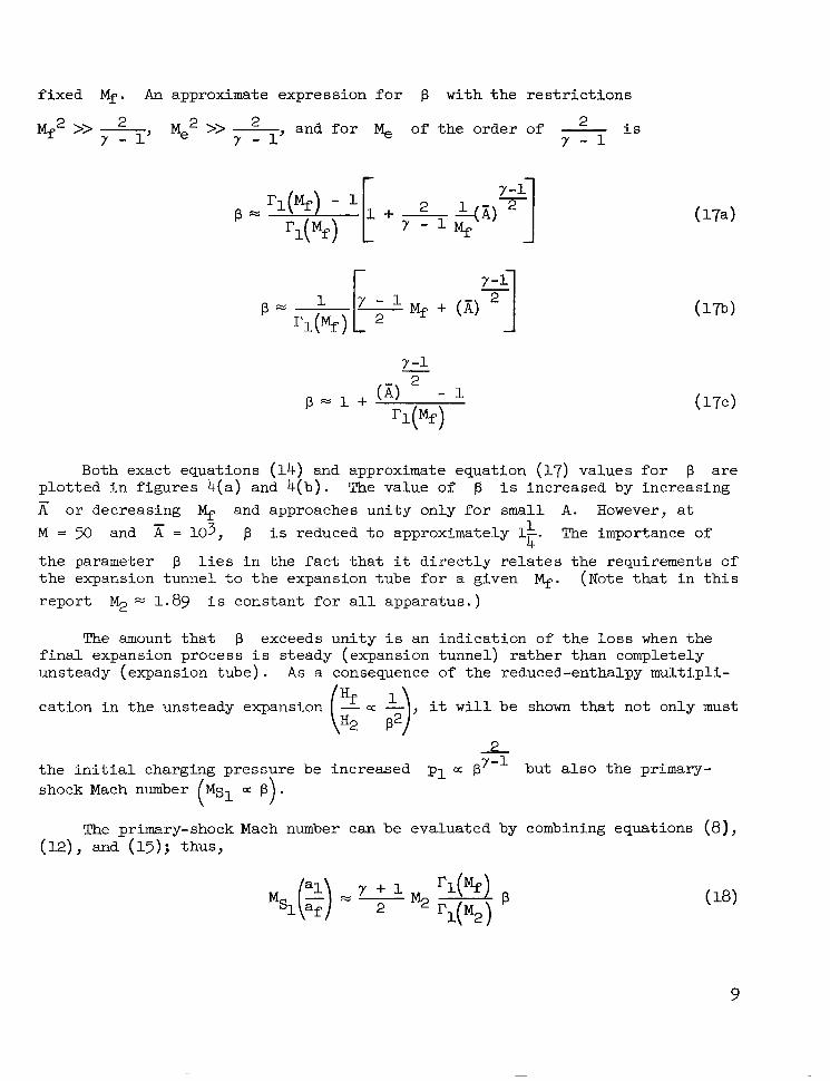
f ixed Mf. An approximate expression for p w i t h t h e r e s t r i c t i o n s
Mf2 >> - 2 Me2 >> - and for o f the o rder o f - i s y - 1' y - 1' Y - 1
(174
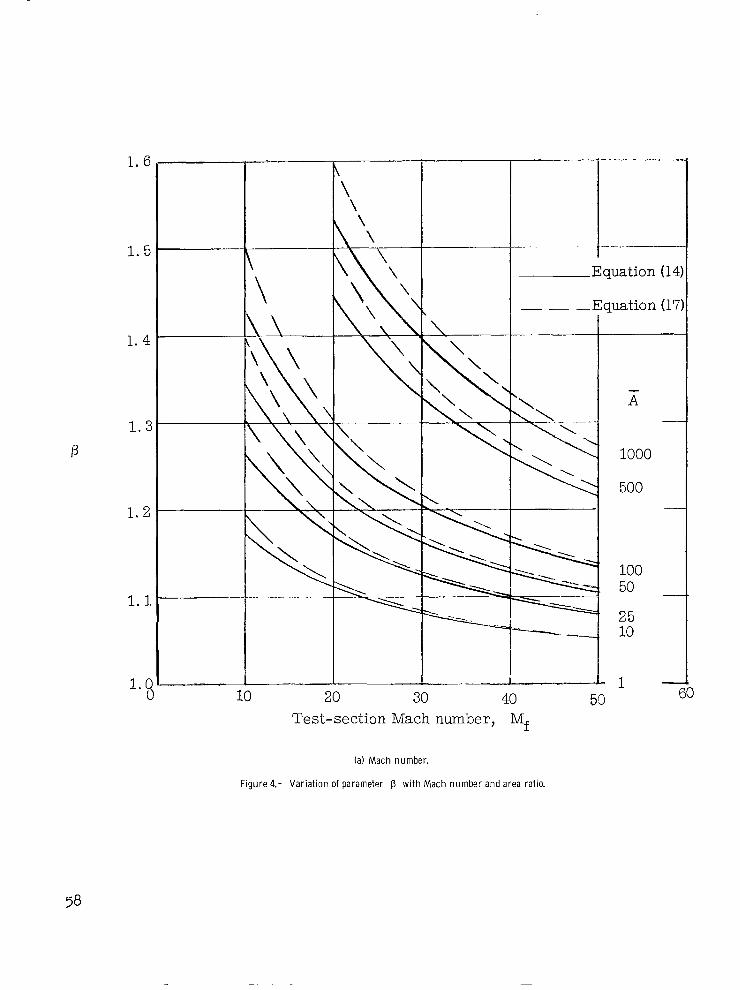
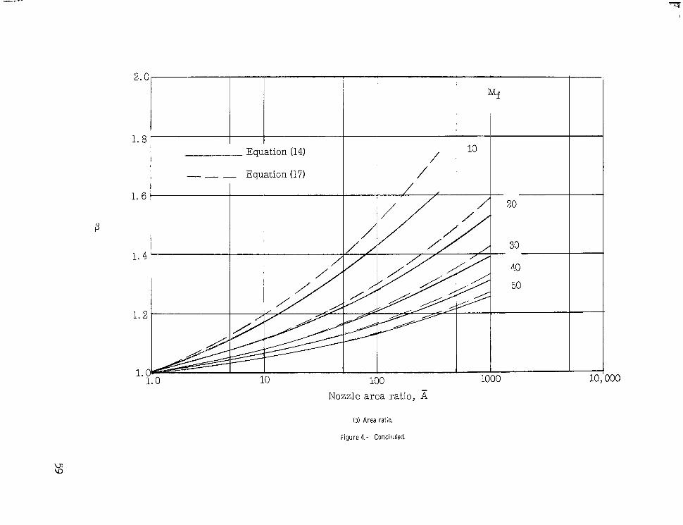
Both exact equations (14) and approximate equation (17) values for p a r e p l o t t e d i n f i g u r e s 4(a) and 4(b) . The value of p i s increased by increasing E or decreasing Mf. and approaches unity only for small A. However, a t M = 50 and = 103, p i s reduced t o approximately 1". The importance of
the parameter p l i e s i n t h e f a c t t h a t it d i rec t ly re la tes the requi rements o f the expansion tunnel to the expansion tzbe for a given Mf. (Note t h a t i n t h i s r epor t ~2 N 1.89 i s cons tan t for a l l appara tus . )
1 4
The amount t h a t p exceeds unity i s an ind ica t ion of t h e loss when t h e f i n a l expansion process i s steady (expansion tunnel) rather than completely unsteady (expansion tube) . A s a consequence of the reduced-enthalpy multipli-
cat ion in the unsteady expansion , it w i l l be shown tha t no t on ly must
_2, the in i t ia l charg ing pressure be increased p1 a p '-' but also the primary- shock Mach number
The primary-shock Mach number can be evaluated by combining equations (8) ' (12), and (15); thus,
9
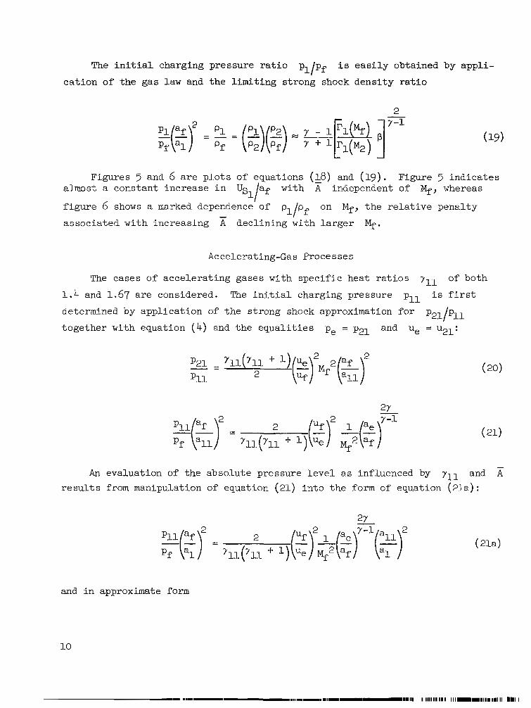
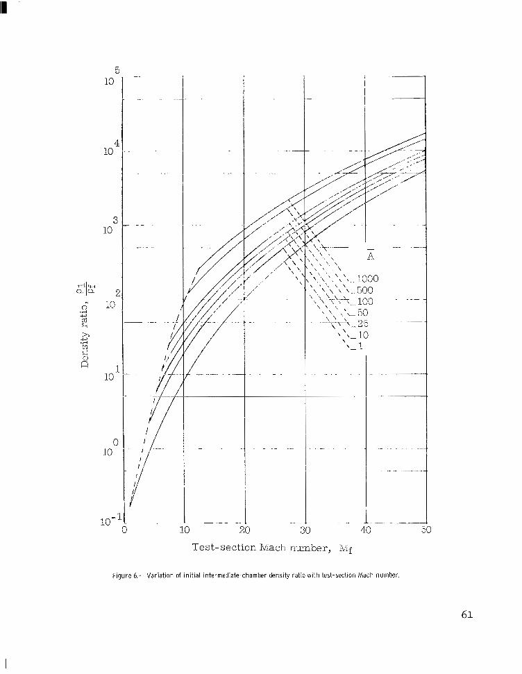
The i n i t i a l c h a r g i n g p r e s s u r e r a t i o pl/pf i s easi ly obtained by appl i -
ca t ion of the gas law and the l imi t ing s t rong shock densi ty ra t io
3
Figures 5 and 6 are p lo ts o f equa t ions (18) and (19). Figure 5 i nd ica t e s almost a cons tan t increase in US with independent of Mf, whereas
f i g u r e 6 shows a marked dependence of p p on Mf, t h e relative penal ty
associated with increasing A dec l in ing wi th l a rger q.
l/af
- 11 f
Accelerating-Gas Processes
The cases o f acce le ra t ing gases wi th spec i f ic hea t ra t ios yll of both
1.4 and 1.67 are considered. The i n i t i a l charging pressure pll i s f i r s t
determined by application of the strong shock approximation for pgl/pl1
together with equation (4 ) and t h e e q u a l i t i e s pe = p21 and ue = u21:
An evaluat ion of the absolute pressure level as influenced by 711 and A -
r e s u l t s from manipulation of equation (21) into the form of equation (21a):
and i n approximate form
10
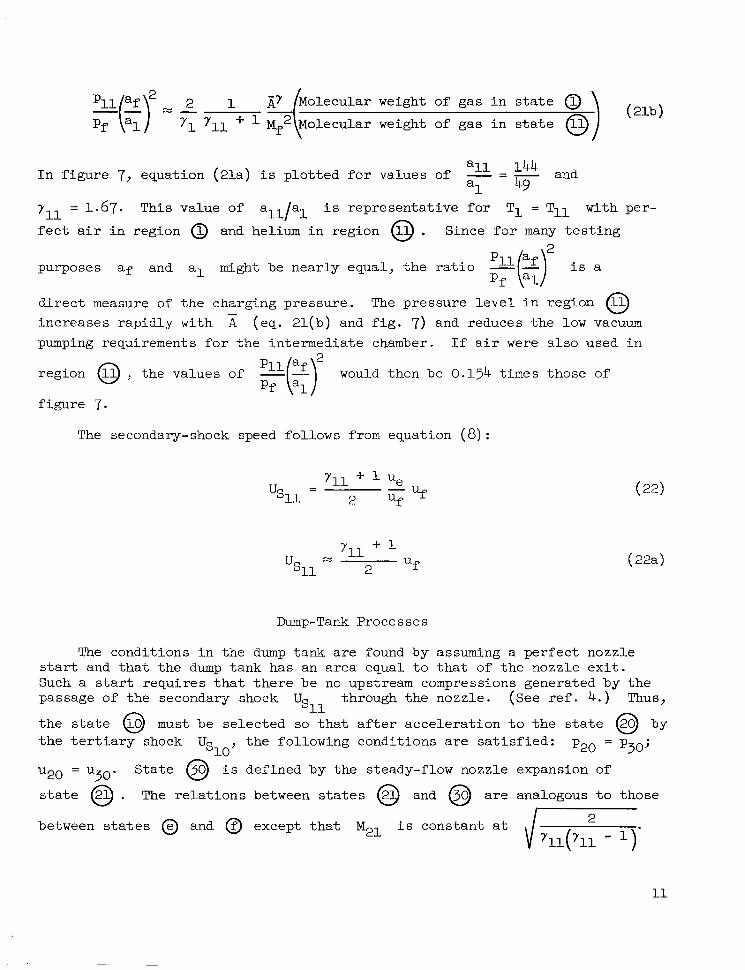
weight of gas in s ta te 0 ( 21b 1
weight of gas in s ta te
I n f i g u r e 7, equation (21a) i s p lo t ted for va lues o f - = - all 144 and a 1 49
yll = 1.67. This value of all/al i s representa t ive for T1 = Tll with per-
f e c t a i r in reg ion @ and helium in reg ion @ . Since for many t e s t i n g -
purposes af and a1 might be near ly equal , the ra t io
d i r e c t measure of the charging pressure. The p res su re l eve l i n r eg ion increases rapidly with (eq. 21(b) and f i g . 7) and reduces the low vacuum pumping requirements for the intermediate chamber. I f a i r were also used i n
0
region 0 , the values of Qkr would then be 0.154 times those of Pf
f i gu re 7.
The secondary-shock speed follows from equation (8) :
Y, 1 + 1 %l
LJ-
2 Uf
Dump-Tank Processes
The condi t ions in the dump tank a re found by assuming a perfect nozzle s tar t and t h a t t h e dump tank has an area equal t o t h a t of the nozz le ex i t . Such a start requi res tha t there be no upstream compressions generated by the passage of the secondary shock through the nozzle. (See ref. 4 . ) Thus,
t h e s t a t e @ must be selected so t h a t a f t e r a c c e l e r a t i o n t o t h e s t a t e @ by t h e t e r t i a r y shock the fo l lowing condi t ions a re sa t i s f ied : p20 = p30;
u20 = u ~ ~ . S ta t e @ i s defined by the steady-flow nozzle expansion of
s t a t e @ . The r e l a t i o n s between states @ and @ are analogous t o those
%l
%o ,
between s t a t e s @ and @ except that M21 i s constant a t 2

Thus with the strong shock assumption for the expression f o r t h e i n i t i a l
nozzle charge pressure i s %o'
The approximate values of u30/u21 and p30/p21 a r e
where
12

2 The nozzle charging pressure parameter of equations (23) i s
p l o t t e d i n f i g u r e 8 f o r y = 1 . 4 with yl0 and yll equa l t o 1 .4 and 1.67. As indicated by equation (23a), this pressure parameter i s only a weak function of a rea ra t io when y = yll and >> 1. (See f igs . 8(a) and 8(b) . ) Lower
charg ing pressures a re requi red for l a rger va lues of A when y # yll.
. .
-
A parameter i l lus t ra t ive of the absolu te p ressure l eve l for the case of a i r as the tes t gas with hel ium or a i r for the o ther charg ing gases would be - %($r, which i s found a s Pf
PlO af p10 af
Pf -($ - Pf (alo)pr This parameter i s p l o t t e d i n f i g u r e 9 f o r t h e r a t i o s - = 1.0 f o r a10
a1
a10 - 144 y = yl0 and - - - f o r ylo = 1.667. These sonic-speed ratios are appro- al 49
p r i a t e f o r T1 = T10 wi th a i r o r he l ium as the nozz le gas in s ta te @ . The
lower pressures (higher vacuums) a r e r e q u i r e d f o r a i r i n bo th s t a t e s @ and @ . The combination of helium i n s t a t e @ and a i r i n s t a t e @ per- mits h i g h e r i n i t i a l pl0 ( f o r Mf > 2.5, z > 2.5) than i f helium were used i n
b o t h s t a t e s @ and @ . The case of yl0 = - 5 and yll = - 7 requi res a 3 5
p10 reduction of about one order of magnitude between = 1 and A = 100,
and the value of pl0 = 5 x 10⁻⁴ pf a t E = 10.
The exac t exp res s ion fo r t he t e r t i a ry shock velocity
be put in to a simpler approximate form by using the s t rong shock re la t ion together with the assumption of a per fec t i n i t i a l nozzle start and equa- t i o n s (3a) and (24) :

1 &en the tes t gas flows through the nozzle from stat
Uf u21 U f + d 2 1
711 - ‘302
- > M 2 S ince for A 2 1, M30 = 21 = , it follows from equa-
t i on (29 ) t ha t u30 > uf . Also, f o r 7 5 7 p30 < pf from equation (30).
Consequently, the unsteady wave system generated by the passage of the test- gas-accelerating-gas interface (between state @ and s t a t e @) through the nozzle must a t t empt t o ad jus t t he s t a t e s @ and @ t o a common ve loc i ty and pressure. A schematic sketch and distance-time (wave) diagram of the processes leading to the es tabl ishment of t h e s t a t e s @ and @ a r e shown i n f i g - ures lO(a) and 10(b). For a p e r f e c t i n i t i a l n o z z l e s t a r t , s t a t e @ i s iden-
t i c a l t o s t a t e @ . The pressure and ve loc i ty of s t a t e s @ and @ ( f i g . l O ( c ) ) must now be matched a t a common point (g,5O) by means of an
upstream wave, s t a t e @ -+ s t a t e @ with dp < 0, and a downstream wave,
11 ’
du
s t a t e @ + s t a t e @ with 2 > 0. These condi t ions are indicated for du
cases I, 11, and 111 by the dashed l ines i n f igure lO(c) . I f bo th ad jus t ing waves are isentropic, the equation governing the wave s t rength p p i s
g/ f
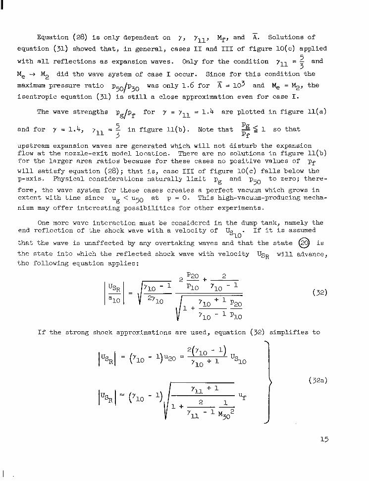
Equation (28) i s only dependent on y , yll, Mf , and x. Solutions of
equation (31) showed tha t , i n gene ra l , c a ses I1 and I11 of f igu re 10( c) appl ied
with a l l r e f l ec t ions as expansion waves. Only for the condi t ion rll = 7 and
Me + M2 did the wave system of case I occur. Since for this condition the
maximum pressure ra t io p50/p30 was only 1 .6 f o r x = lo3 and M, = Q, t h e
isentropic equat ion (31) i s s t i l l a close approximation even for case I.
5
The wave s t rengths pg/pf f o r y = 7 - 1 . 4 a r e p l o t t e d i n f i g u r e l l ( a ) 11 -
- i n f i g u r e l l ( b ) . Note t h a t 5 1 s o t h a t and f o r y = 1.4,
upstream expansion waves are generated which w i l l not disturb the expansion flow a t the nozzle-exi t model location. There are no so lu t ions i n f i gu re l l ( b ) for the l a rger a rea ra t ios because for these cases no posit ive values of pf w i l l sa t i s fy equat ion (28); t h a t i s , case 111 of f igu re lO(c ) f a l l s below the p-axis . Physical considerat ions natural ly l i m i t p and p50 t o zero; there-
fore , the wave system for these cases c rea tes a per fec t vacuum which grows i n extent with time since ug < ~ 5 0 a t p = 0. This high-vacuum-producing mecha- nism may o f fe r i n t e re s t ing poss ib i l i t i e s fo r o the r expe r imen t s .
P 711 - Pf
g
One more wave in t e rac t ion must be considered in the dump tank, namely the end r e f l ec t ion of the shock wave with a ve loc i ty of . I f it i s assumed
t h a t t h e wave is unaffected by any overtaking waves and t h a t t h e state @ i s
t h e s t a t e i n t o which the r e f l ec t ed shock wave with veloci ty UsR w i l l advance, the following equation applies :
%o
p20 2
*lo 710 2-+
- 1
If the strong shock approximations are used, equation (32) simplifies to
(32a)
1 + - 1
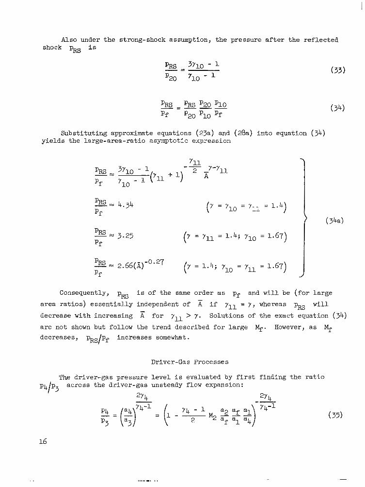
Also under the strong-shock assumption, the pressure after t h e r e f l e c t e d shock p~~ i s
Substituting approximate equations (23a) and (28a) into equation (34) yields the large-area-rat io asymptot ic expression
-0.27 - x pRs 2.66(X) (7 = 1.4; Yl0 -
- 711 = 1.67) J Pf
Consequently, pRs i s of the same o rde r a s pf and w i l l be ( f o r l a rge
a rea ra t ios ) essent ia l ly independent o f A if yll = y , whereas pRs w i l l
decrease with increasing x f o r yll > 7 . Solutions of the exact equation (34) a re no t shown but fol low the t rend descr ibed for large q. However, as Mf decreases, pxs/pf increases somewhat.
-
Driver-Gas Processes
The dr iver-gas pressure level i s evaluated by f i r s t f ind ing t he r a t io p4/p3 across the driver-gas unsteady flow expansion:
2y4 274 Y 4-1
”
Y4-1 (35 )
16

The r a t i o of d r iver -gas p ressure to t es t -gas p ressure resu l t s from combining equations (12) , (13), and (33) :
274 2Y
The r a t i o of driver-gas pressures required for expansion-tunnel operation
t o t h a t f o r expansion-tube operation , for the case of i d e n t i c a l t e s t -
sect ion condi t ions, i s then
2Y (p4)ETun
(p4> ET = P
- 74 - %(Mf) a f
Y 4-1 1 -
2 M2 rl(M2)
If a dr iver gas with a very high speed of sound i s used so t h a t 2 << 1, a4
the expression in brackets approaches uni ty . If, in addi t ion , the approxima- t i o n ( l 7 c ) i s used for p, the dr iver-gas pressure ra t io becomes

If the assumption i s added t h a t Mf >> - 2 y - 1'
l 2
- + . . .
Driver-gas pressure ra t ios from equation (36) a re p lo t t ed i n f i gu re 12 f o r - 5 a4 T4
Tf the case of y4 = 3' - =
af , with values of - = 10, 25, and 50. The
increase in dr iver-gas pressure with increasing nozzle area ra t ios i s evident together with a decrease in p4 as a4(T4) increases . Such a t rend was
expected from shock-tunnel experience. The decreasing difference between tunnel and tube pressures as Mf increases i s also apparent, a t rend predicted simply by the approximation equations (38). A t l a rge $, (p4/pf) f o r E = 10 3 i s about ten t imes (p4/pf) for K = 1.
WNGTHS OF COMPONENT SECTIONS AND TESTING TIMES
Accelerating Chamber
The acce lera t ing chamber length 2s2 i s the fundamental one i n t he apparatus since it determines the testing t ime. Let At2 be defined as the t ime interval a t the nozzle entrance between the arr ival of t h e t e s t g a s and t h e t r a i l i n g edge of the upstream expansion fan ; t h a t i s , it i s the t ime for which t h e s t a t e @ ex i s t s a t t he nozz le en t r ance ( f ig s . 1 and 13) and would be t h e t e s t t i m e f o r a zero-length nozzle. The nondimensional equation for At2 i s
o r i n an approximate form by subst i tut ing equat ions ( l a ) and (2a):
18

The test t ime parameter - afnt2 of equation (39) i s p l o t t e d i n f i g u r e 14. Note Q32
t h a t for a given % s ign i f i can t ga ins i n At2 are obtainable by the tunnel
mode of operation; equation (39a) indicates gains roughly proport ional to r-1
( E ) . Also shown i n f i g u r e 1 4 i s the nonreflected shock tunnel t es t ing t ime
together w i t h t icks indicat ing the values of A r equ i r ed t o a t t a in by a steady nozzle expansion. The strong-shock approximations require:
( ? ? ) NRS
- = 0 . 0 0 3 ~ ~ 5
The length 2 i s used f o r t h e shock tunnel since there are no 1 l engths
required. S1 s2
The zero-nozzle-length expansion-tunnel test times are much shorter than those for the nonref lec ted shock tunnel , a l though the l a t te r , of course, must have a much la rger a rea ra t io nozz le for the same M f . The e f f e c t of nonzero nozzle length w i l l be discussed subsequently.
Nozzle
In o rder to spec i fy the nozz le l ength l ~ , consideration must be given t o t h e t i m e l o s t i n s t a r t i n g and stopping the nozzle. An ana lys i s of t h i s problem for expansion-tunnel operation will be based on the pe r f ec t s ta r t approach. (See ref 4.) Expressions for the nozzle- t ime losses w i l l be found for nozzles i n which t h e l o c a l a r e a r a t i o v a r i e s w i t h b o t h t h e f irst and second power of d i s t a n c e ( l i n e a r a r e a r a t i o and conical nozzles) .

The notat ions used are Atflow, At,, and At- f o r t h e times required for a t r ansve r sa l of the nozzle by a f l u i d p a r t i c l e , a downstream cha rac t e r i s t i c wave (which t r a v e l s w i t h l o c a l v e l o c i t y u + a ) , and an upstream characterist ic wave (which t rave ls wi th loca l ve loc i ty u - a ) , respect ively. The following expressions are v a l i d f o r t h e times shown i n f i g u r e 13:
For a nozzle where A( k ) = A,( 1 + CE)
t
where
A1 so
20
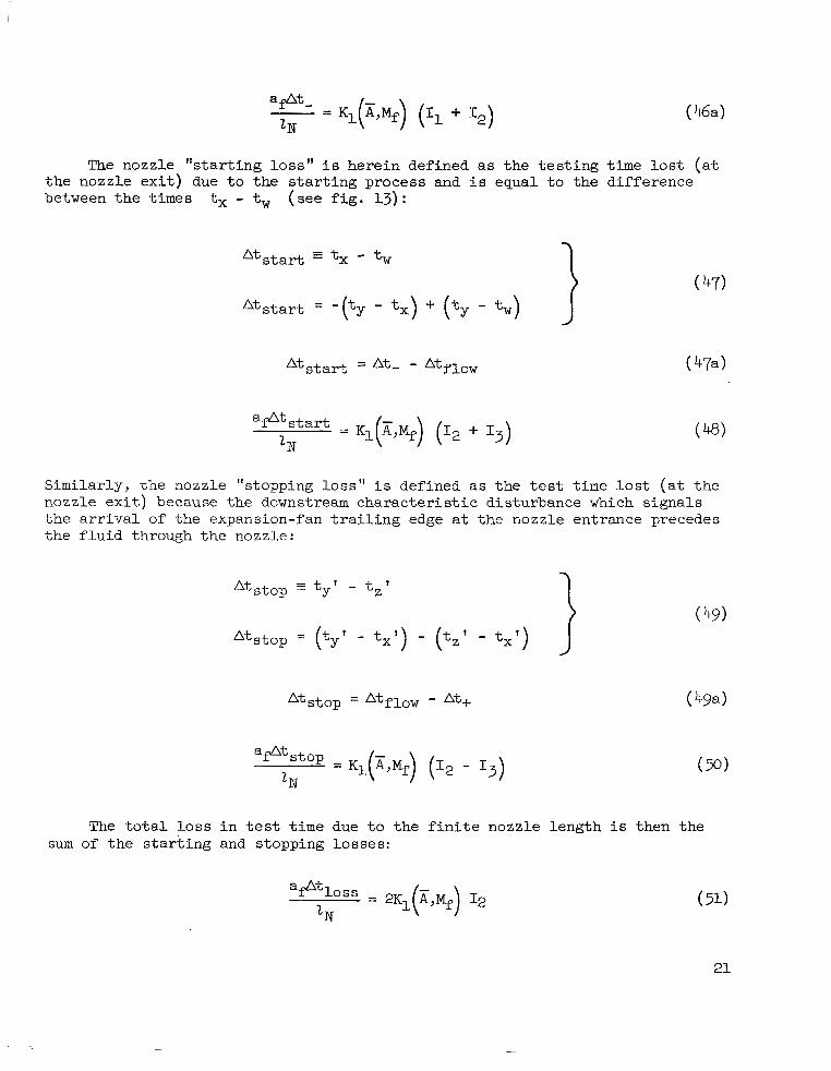
The nozzle "s tar t ing loss" i s herein defined as t h e t e s t i n g time l o s t ( a t the nozz le ex i t ) due t o t h e s ta r t ing p rocess and i s equal to the d i f fe rence between t h e times tx - tw ( s e e f i g . 13) :
Similarly, the nozzle "stopping loss" i s defined as t h e t e s t t i m e l o s t ( a t t h e nozzle exi t ) because the downstream charac te r i s t ic d i s turbance which s igna l s t h e a r r i v a l of the expans ion- fan t ra i l ing edge a t the nozzle entrance precedes the f luid through the nozzle:
A t ,top f ty ' - tz ' 1 (49)
The t o t a l loss i n t es t time due t o t h e f i n i t e n o z z l e l e n g t h i s then the sum of t h e s t a r t i n g and stopping losses:
21
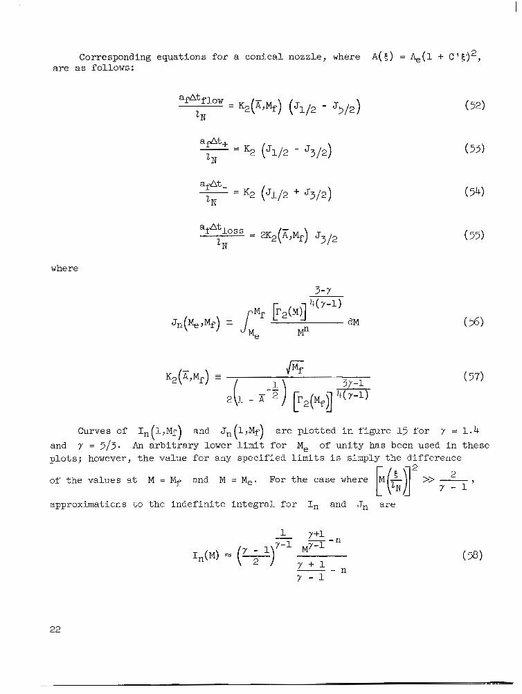
Corresponding equations f o r a conical nozzle, where A( E) = &(l + C ' 5 j 2 , are as fo l lows:
"fA"f1ow = K2 A Mf ( ' ) (51/2 - '5/2) (52) IN
a+t+
I N - = K2 (JL/2 - J3/2) (53)
" a@t- - K2 (J1/2 " J3/2) (54) IN
af%oss
l N = x*(x+r) ~ 3 / 2 ( 55)
where
3-Y
Curves of I n ( l , M f ) and J n ( l , M f ) a r e p l o t t e d i n f i g u r e 15 f o r y = 1 . 4 and y = 5/3. An a r b i t r a r y lower l i m i t f o r Me of unity has been used in these p lo t s ; however, the value for any specif ied limits i s simply the d i f fe rence
of t he va lues a t M = Mf and M = %. For the case where 2
approximations t o t h e i n d e f i n i t e i n t e g r a l f o r I n and Jn are
22

These approximations are shown a s t h e dashed curves i n f i g u r e 15. It i s evi- dent that such approximations would be very good f o r e v a l u a t i n g t h e f i n i t e i n t e g r a l when Mf and Me are not small.
I n o rde r t o eva lua te t he f r ac t ion of the t ime At2 lost in the nozzle processes, a nozzle loss parameter i s introduced and defined as
f ~ ~ s s ) E T u ~ ~ ) . This parameter i s p lo t ted for the l inear -area nozz le i n
f i gu re 16 together with the approximate equation:
Equation (60) r e t a i n s o r d e r s i n t h e r e c i p r o c a l of A which have been previously neglected. This retention i s necessary to ga in accuracy for th i s case .
-
The nozzle losses are not excessive for 2~ < 2 . I n f a c t , f o r l a r g e A, -
s 2 the nozzle length can a c t u a l l y exceed the accelerating-chamber length before the t es t t ime vanished ( tha t i s , At los s = At2). The reason tha t the x = 1 curve does not have Atloss = 0 i s t h a t by d e f i n i t i o n t h e t e s t t i m e i s bounded by the upstream and downstream c h a r a c t e r i s t i c s from the nozzle entrance ( f i g . 13) . Consequently, f o r = 1 and Mf >> 1, the nozzle l o s s parameter approaches two.
The comparable loss parameter for the nonreflected shock tunnel i s a l s o p l o t t e d i n f i g u r e 16 by using the following approximation:
I II
The values of A of t h e shock tunnel are indicated by t icks on the curve.
A t a given value of Mf and f o r t h e same ra t io o f Z H / l S , these curves i n d i c a t e t h a t Atloss/At* i s greater for the expansion tunnel than for t he shock tunnel. However, to obtain high 4, the value of x becomes extremely la rge in the nonref lec ted shock tunnel for example, a t Mf = 50, Ams = lo6) -
so t h a t f o r a given nozzle wall slope the shock-tunnel nozzle length lN
might be much l a rge r t han t ha t of the expansion tunnel. A fur ther considera- t i o n of t h i s problem can be found in the "Discuss ion" par t of th i s paper .
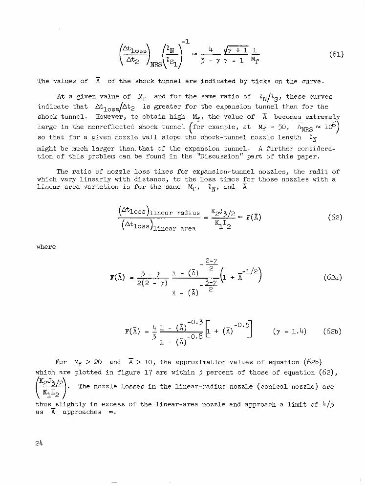
The r a t i o of nozzle loss t imes for expansion-tunnel nozzles , the radi i of which vary l inear ly wi th d i s tance , to the loss times for those nozzles with a l i n e a r a r e a v a r i a t i o n i s f o r t h e same Mf, lN7 and A
-
where
2-r
1 - (X) 2
For > 20 and x > 10, the approximation values of equation (62b) which a r e p l o t t e d i n f i g u r e 17 are within 3 percent of those of equation (62),
( K l l g ) . The nozz le losses in the l inear - rad ius nozz le (conica l nozz le) a re
t h u s s l i g h t l y i n excess of the l inear-area nozzle and approach a l i m i t of 4/3 as A approaches 03.
-
24
Another aspect of the nozzle s tar t ing process which was considered was t h e nozzle-length requirement t o ensure that the accelerat ing gas f low had been completely established in the nozzle before the test gas reached the nozzle e x i t . T h i s c r i t e r i o n p r o h i b i t s any interference between the nozz le s ta r t ing processes of the two gases. It was found t h a t th is requirement was s a t i s f i e d as long as LN was no greater than approximately one-half for > 10 and for values of yll equal to bo th 1.4 and 1.67.
l S 2
Intermediate Chamber
The intermediate chamber length 2 i s determined so t h a t t h e r e f l e c t i o n
generated a t the intersect ion of the leading edge of the expansion fan with the driver-gas-test-gas interface (between 0 and @ ) w i l l a r r i v e a t the nozzle entrance simultaneously with t h e t r a i l i n g edge of the expansion fan. (See f i g . 1.) The governing equation i s
s1
and t h i s r a t i o of 2sl#s2 i s p l o t t e d i n f i g u r e 18. For a given value of K and 1 the l eng th 2 decreases rapidly with increasing M (approximately
as M-3 f o r l a r g e M) . And a t a constant (large) value of M, t h e r a t i o Tsl/2s2 increases nearly as ~ 0 . 6 . ~ h u s , expansion-tunnel operation requires
longer intermediate chambers than those for an expansion tube with equal 2 . I n t h e extreme case of l a rge and low Mf, t he l eng ths 2 and lS2 a r e
of t h e same order; however, for high and l a rge K, i s only a few
percent of 2
s2 S1
s2
S1
lS1
s2 *
Dmp -Tank Length
An approximation t o t h e dump-tank length 2 may be found by introducing SR the following simplifying assumptions: (a) the nozzle length i s zero; (b) the shock v e l o c i t i e s and U are constant during shock-wave t r a v e r s a l of
t h e dump tank; and (e) the total t raversal t ime of these shocks i s e q u a l t o t h e t ime i n t e rva l between t h e a r r i v a l a t the nozzle of the shock wave and
t h e t r a i l i n g edge of the expansion fan. Thus
%o SR
%l
which can be operated on by subst i tut ing equat ions ( 3 ) , ( 2 8 ) , ( 3 2 ) , and ( 3 9 ) p lus t he r e l a t ion
- At, = ue 'Is2
t o y i e l d
The var ia t ion of with Mf i s shown i n f i g u r e l g ( a ) f o r yl0 = - 5 3
and yll = 7 and i n f igure 19(b) for yl0 = yll - - - 5 . Larger values of I
are required with increasing x, but the percentage increase i s small f o r
l a rge Mf. Also the values of 2 are smaller when yll = ra ther than -.
Not shown a r e p l o t s f o r yl0 = yll = -, but these values are approximately two-
5 3 SR
SR 3 5
7 5
t h i r d s t h o s e f o r ylo - - 5 yll = 7 ( f i g . l g ( a ) ) . 5
Driver-Chamber Length
The dr iver c ross -sec t iona l area i s assumed t o b e e q u a l t o t h a t of t h e intermediate and expansion chambers. The dr iver l ength i s determined so t h a t t he r e f l ec t ion of t h e d r i v e r r a r e f a c t i o n wave off the end p l a t e will pass through the point m ( f i g . 1) where the en t ropy d i scont inui ty between 0 and @ in te rsec ts the l ead ing edge of t h e main expansion fan. For these conditions
26

From f igu res 20 which a r e drawn for values of a4/af equal to those of f i gu res 12, it i s evident that Z D / Z ~ ~ decreases with increasing A. Conse-
quently, in terms of matching the d r ive r and intermediate chambers, the expan-
-
sion tunnel i s
increases with
as i l l u s t r a t e d
d r ive r l eng ths
l e s s r e s t r i c t i v e on dr iver l ength . However, since
A ( f i g . 18) , t h e n e t r e s u l t i s an inc rease i n lD/lS2 with X
i n f i g u r e 21 for the intermediate value of 2 = 5(e). The
i n t h e expansion tunnel are thus s ignif icant ly larger than those af
of the expansion tube; for example, a t = 50,
a t x = 100 and approximately 25 a t x = 1000. However, even a t x = 1000, 1~ 0.011 f o r = 30. s2
DISCUSSION
Diaphragm Bursting
Secondary diaphragm.- Reference 1 pointed out the cr i t icalness of the secondary-diaphragm burst because of the fact that only an extremely small p a r t of t h e g a s i n i t i a l l y i n t h e i n t e r m e d i a t e chamber i s ac tua l ly u sed fo r t e s t ing . If the ex ten t of t h i s g a s i n s t a t e 0 i s designated as z, from cont inui ty
Pf - P1
z = - A U rat,
and by substitution, equation (67) becomes

Thus, for equal values of 2s2 and t e s t cond i t ions @ t h e r a t i o
length z for the expans ion tunnel to tha t for the expans ion tube
The r e l a t i o n of equation (67) i s p lo t t ed i n f i gu re 22 for ZN shows order-of-magnitude gains in z/2s2 with increasing A. The
of t h e
i s
= 0 and primary part
of t h i s g a i n i s a t t r i b u t a b l e t o s i m p l y t h e f a c t t h a t t o s t o r e t h e same mass of " t e s t s lug" i n a reduced cross-sectional area requires a longer length i f t h e i n i t i a l charge densi t ies were the same. The o ther cont r ibu t ion to the ne t ga in i s a r e s u l t of the increased tes t - s lug mass due to increased tes t ing t ime more than compensating f o r the increase with of t h e i n i t i a l charge den-
- Y+l - 2 2
s i t y pl. For M, >> - the ga in i s p ropor t iona l t o (x) y - 1' ( e s . (69)) a t
a given q.
The secondary-diaphragm burs t ing problem i s a l l ev ia t ed even f u r t h e r when diaphragm opening time i s considered. If t h e diaphragm i s assumed t o be near i t s rupture s t ress a t pressure ply for a given material the opening time i s proport ional to the tab radius divided by the square root of the primary shock pressure ra t io p2/p1. The f l u i d mass passing the diaphragm stat ion during
1 - - opening i s thus inc luded in
indication of the secondary
28
2 a length proport ional to u2d(") a ald. AE
P l diaphragm problem i s then t he r a t io z/d with

larger values of z/d desired. For t h e same tes t -sect ion condi t ions 0 , t e s t - sec t ion s ize , and accelerating-chamber length Zs2, t h e r a t i o s of z/d a r e
found from equation (69) t o be
Y “2
For 100 and x x 1000, t h e r a t i o s of equation (70 ) are approximately 2 .5 X lo3 and 1.25 x lo5, respec t ive ly , and i l l u s t r a t e t h e l a r g e g a i n s i n a l l e - v i a t ion of t h e secondary-diaphragm problem for the expansion tunnel.
The length ztest w i l l be s l igh t ly smal le r than z2 t h a t i s , ( Z t e s t = ‘2 Attest) due to the nozz le losses .
At2
\
However, t h e diaphragm burs t ing
a f f e c t s t h e downstream p a r t of t he t e s t gas , and t h i s g a s i s a l s o t h a t used i n th.e nozzle starting process. Consequently, an imperfect diaphragm burst influences first t h a t p a r t of the gas considered expendable in start ing the nozzle of the expansion tunnel.
Although t h e secondary-diaphragm bursting problem can be drastically reduced f o r l a r g e A, t he problem i s not e l iminated. I f the diaphragm i s assumed t o s h a t t e r and the resu l tan t f ragments then requi re acce le ra t ion to the local free-stream velocity, simple approximations show t h a t t h e momentum of these fragments i s not negl igible compared wi th the momentum of the tes t -gas s lug ( t ha t i s , t he mass of t h e t e s t g a s s l u g pLz& i s not orders of magnitude grea te r than the diaphragm mass). An experimental study (ref. 5 ) using poly [ethylene terephthelate] and cellophane diaphragms f o r IVL-,~ 3 considers
t h i s opening problem. Since the pressure ratio across the incident and/or r e f l ec t ed shock waves increases with % t he problem f o r shock speeds p e r t i -
nent to expansion-tunnel operation i s not as severe as a t % N 3 . If t h e
diaphragm p e t a l s a r e r e s t r a i n e d so tha t they fo ld back aga ins t the wal l ra ther than proceeding downstream, the re i s a p o s s i b i l i t y t h a t t h e momentum l o s t from the stream may be reduced. Another p o s s i b i l i t y i s the use of electrodynamic f o r c e s t o a s s i s t t h e diaphragm opening.
1’
1
Primary diaphragm.- The primary-diaphragm rupture problem should be m i t i - - gated by increasing A because of t h e smaller diameter diaphragm cross section. If the diaphragm i s s t r e s sed t o rup tu re a t a certain percentage of p4, t he opening time i s proport ional to the diameter and w i l l decrease with increasing
fo r g iven t e s t - sec t ion s i ze s and conditions.
Ter t i a ry diaphragm.- A t h i r d diaphragm, not present for expansion-tube operation, i s located a t the nozzle entrance of the expansion tunnel. However, t h i s diaphragm does not require a perfect rupture s ince the accelerat ing gas from ZS as w e l l as t h e i n i t i a l p a r t of the gas from 2sL used t o start t h e
nozzle both pass the diaphragm s t a t ion p r io r t o t he a r r iva l o f t he gas com- p r i s i n g t h e t e s t slug.
2
Driver Analysis
The dr iver p ressure ra t io p4/pf ( f i g . 12) and d r ive r l eng th r a t io
"/2s2 ( f i g . 21) increase with E . However, t h e s e r a t i o s are not a t r u e meas-
ure of the eff ic iency of the appara tus s ince for a given tes t -sect ion s ize , the -112
dr iver c ross -sec t iona l area decreases in p ropor t ion to A and a l so for a given t e s t time k 2 , t h e l e n g t h 2s2 decreases as x increases . A per-
t inent parameter which considers a l l t hese e f f ec t s i s the energy parameter E which i s propor t iona l to the energy requi red in the d r iver per un i t t es t - sec t ion a rea , t es t t ime ( 2 ~ = 0 ) , and s t a t i c p re s su re :
-
where
E = (pcVT)4(I - %) Ae2D T4
and T i i s the ini t ia l temperature before energy addi t ion in the dr iver .
Figure 23 shows the dependency of E on both Mf and A f o r 74 = - - 3 3
and values of '' - - - - T4 equal to those o f f igures 12 and 20. Lower values of T, TP I I
r e s u l t a s i n c r e a s e s a t a given Mf and T4/Tf; and the reduct ions
become more pronounced as T4/Tf increases . More e f f ic ien t opera t ion appears t o occur for the higher T4/Tf value a t t h e same Mf. and A. Thus, when the expansion tunnel i s compared with the expansion tube on the nondimensional
-

energy basis 3, the advantages of the expansion-tunnel mode of operation are very significant. This energy reduction i s an important consideration for arc drive-rs which use capacitor bank discharges, inductive storage systems, and so f o r t h .
Efficiency
The i d e a l e f f i c i e n c y of the expansion tunnel i s defined as
Test-section energy Driver energy l-io = .~
- ($ Uf2)(PfUfA+t2) Mf3 70 -
- _" E 2 E f (73)
This eff ic iency i s "ideal" because there are no nozz le s ta r t ing losses , no scoop-off l o s ses , and so forth considered. Figure 24 shows that a l though qo decreases with Mf f o r f i x e d x, it increases very s ignif icant ly with E
T 4 f o r a given Mr. For - = 25 and Mf = 50, q0 equals 0.003 f o r A = 1, -
TQ I
0.025 f o r x = 100, and 0.033 for A = 1000. -
If the physical dimensions of the nozzle are such that < 6, the nozzle d entrance sect ion must be designed to cap tu re on ly t ha t pa r t of t h e g a s i n t h e acce lera t ing chamber enclosed within a stream tube of diameter d l . (See sketch ( a ) . )
a D
Consequently, the overall efficiency which is the product of the ideal effi- ciency, the nozzle starting efficiency, and the nozzle capture efficiency is
Viscous Effects
Another problem pointed out in reference 1 was the viscous effect in the accelerating chamber. One measure of the effect of viscosity is the Reynolds number based on diameter. The ratio of N R ~ , ~ in the accelerating chamber to NR~,D of the test section (which is also the Reynolds number ratio for the accelerating chambers of an expansion tunnel to that of an expansion tube for the same Af and Mf ) is
(NReJd)accelerating chamber pe'ed pf
and for p a 9
- ( Y - l b 1 (NReJd)accelerating chamber = (ii) - d
(NRe,D)test section d' I ( 75)
where
Equation (75) is plotted in figure 25 for UI = r;' which is a typical value for air. This figure shows small gains in the Reynolds number ratio with increasing A when d' = d.
3
-
Another measure of the effect of viscosity is the ratio of 6/d where 6 is the boundary-layer thickness which would develop in a length 2 on a
semi-infinite flat plate with an external flow equal to the flow conditions @ O r @ ; thus,
s2
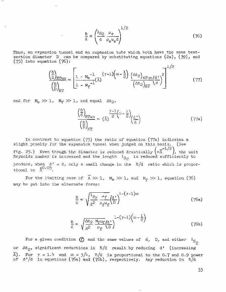
Thus, an expansion tunnel and an expansion tube which both have the same t e s t - section diameter D can (75) into equat ion (76) :
and f o r M, >> 1, Mf >>
be compared by subst i tut ing equat ions (2a) , ( 3 9 ) , and
1, and equal At,,
JET
produce, when d ' = d , only a t i o n a l t o A -0.05
For the l imit ing case of may be pu t in to the a l te rna te
In con t r a s t t o equa t ion (75) t h e r a t i o of equation (77a) ind ica t e s a s l igh t pena l ty for the expansion tunnel when judged on t h i s basis . (See
f i g . 25. ) Even though the diameter i s reduced d r a s t i c a l l y (ar ), t he un i t Reynolds number i s increased and the length i s reduced suf f ic ien t ly to
4 2
Is2 small change i n t h e 6/d r a t i o which i s propor-
- A >> 1, Me >> 1, and % >> 1, equation (76)
forms :
6 - a d
50: d /R(GL) For a given condition @ and t h e same values of d,
( 76b )
D, and e i t h e r 2 s2
o r At2, s ign i f i can t r educ t ions i n 6/d resul t by reducing d ' ( increas ing
A). For y = 1 . 4 and CU = 314, 6/d i s p ropor t iona l t o t he 0.7 and 0.9 power of d ' /d in equat ions (76a) and (76b) , respect ively. Any reduct ion in 6/d
33

r e s u l t i n g from decreasing d'/d i s obtained a t t h e expense of reduced nozzle capture eff ic iency and requi res an inc rease i n d r ive r p re s su re and energy. This penalty may o n l y b e c r i t i c a l a t m a x i m u m f a c i l i t y performance since excess d r ive r capab i l i t y would be ava i lab le a t "off-design" conditions. One must a l s o consider the danger of t ransi t ion to turbulent f low as d ' /d i s decreased
s ince the Reynolds number - increases . If t rans i t ion occur red , the asse t
of a decreasing laminar ratio of 6/d with decreasing d'/d would become a t u r b u l e n t l i a b i l i t y .
peued
P e
Thus i n regard t o t h e v i s c o u s e f f e c t s , t h e r e do not appear t o be e i the r large gains or penal t ies for the expansion tunnel compared with the expansion tube for d ' = d. However, f o r d ' < d, there i s a poss ib l e a l l ev ia t ion of t h e v iscous e f fec ts a t t h e expense of performance capab i l i t y .
Low Vacuum Considerations
Accelerating chamber.- The pressure l eve l pll/pf i n the acce le ra t ing
chamber increases with x ( f i g . 7) and consequently reduces the low pressure requirements in this sect ion. This reduct ion offers s ignif icant gains in another practical aspect for the expansion tunnel over the expansion tube. The low values of pll/pf f o r A = 1 at h igh K may r e s t r i c t t h e g a s i n
s t a t e @ t o helium or hydrogen which have high sound speeds. (See ref. 1. ) However, for the expansion tunnel , the level of pll/pf i s r a i sed su f f i c i en t ly
so t h a t t h e same gas can be u sed bo th fo r t he t e s t gas i n s t a t e 0 and the acce le ra t ing gas i n s t a t e @ . Thus any diffusion of the accelerat ing gas back i n to t he t e s t gas ac ross t he i n t e r f ace between @ and @ would be p a r t i c l e s of t h e same molecular species which, through coll isions, should soon reach the ambient temperature of the test gas. Thus the diffusion contamina- t i o n problem could be cu r t a i l ed .
Another advantage of using the same g a s i n s t a t e s @ and @ would be t h a t t h e g a s i n t h e boundary l aye r on a model would cons is t o f the cor rec t t es t gas pa r t i c l e s even be fo re a r r iva l of t h e t e s t g a s i t s e l f . Consequently, the boundary l a y e r could probably equilibrate more r a p i d l y t o t h e new t e s t g a s flow condition than i f it i n i t i a l l y c o n t a i n e d a f o r e i g n g a s i n s t a t e @ .
Dump tank.- For the boundary conditions of a "perfect start" f o r t h e accelerating gas, the nozzle charging pressures pl0/pf required drop signif- i can t ly wi th A. (See f igs . 8 and 9 and eq. (23). ) However, it may be possible t o r a i s e t h e p r e s s u r e above t h e pl0 values shown and accept an i n i t i a l imper- f e c t s t a r t because the perfect start conditions produce pressures and v e l o c i t i e s which generate upstream expansion waves i n t h e dump tank when the accelerat ing- gss - tes t -gas in te r face a r r ives . Thus an inc rease i n pl0 might be t o l e r a t e d
with a reduced-strength dump-tank expansion wave. It i s not known whether t h e
-
34
pressure could be raised to the point where t h i s expansion wave had zero s t rength p without slowing down the accelerating-gas nozzle start by an
unacceptable amount. ( g. = Pf)
A fur ther considerat ion of the p ressure i s that it does not have t o plo meet an exact value but only an upper l i m i t . Thus, i n c o n t r a s t t o t h e expan- sion tube where the lowest charging pressure must be closely regulated since it determines the strength of the primary expansion wave and hence t h e test conditions, for the expansion tunnel only an upper l i m i t need be s e t a t t h i s lowest pressure pl0. This condition i s very des i rab le from an operating viewpoint.
Ef"fect of Nozzle Configurations
General effect .- The nozzle design for expansion-tunnel operation i s sig- n i f i c a n t l y d i f f e r e n t from t h a t i n conventional wind tunnels o r shock tunnels because the entrance Mach number Me i s very large. The boundary condition of both large entrance and t e s t - sec t ion Mach numbers requi res re la t ive ly long noz- z l e s . For example, i f M, = 10, the f low along the nozzle center l ine does not even start t o expand u n t i l t h e d i s t a n c e downstream of the nozzle entrance i s equa l t o 10 acce le ra t ing chamber r a d i i .
I f a v a r i a t i o n i n t e s t - s e c t i o n Mach number i s t o be obtained simultan- eously with no f low inc l ina t ion or ve loc i ty g rad ien t i n t h e t e s t s e c t i o n , con- toured nozzles are required for a l l combinations of M, and M f . Each such nozzle would have to be co r rec t ed fo r v i scous e f f ec t s which produce both a non- uniform entrance veloci ty prof i le as wel l as a nozzle boundary layer. Rather than consider such a m u l t i p l i c i t y of nozzles , the a l ternat ive of conical noz- z l e s i s t r e a t e d b r i e f l y i n t h i s s e c t i o n with t h e a d d i t i o n a l r e s t r i c t i o n of uniform entrance conditions.
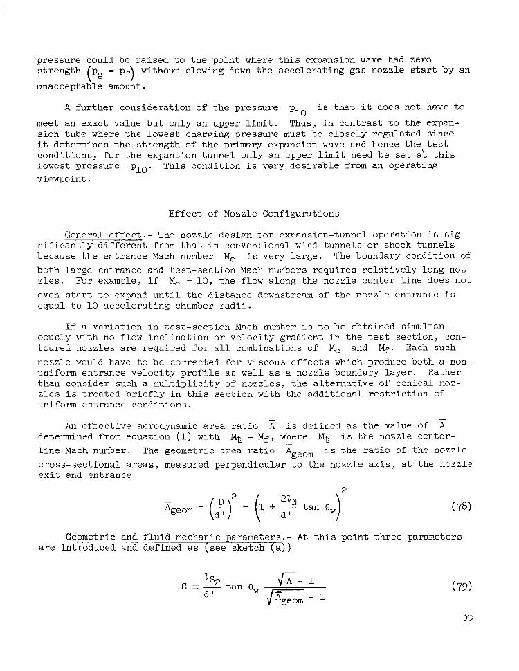
An e f f e c t i v e aerodynamic a r e a r a t i o A i s def ined as the value of x -
determined from equation (1) with % = M f , where % i s the nozzle center- l i n e Mach number. The geometr ic area ra t io Ageom i s t h e r a t i o of the nozzle c ross -sec t iona l a reas , measured perpendicular t o t he nozz le ax i s , a t the nozzle e x i t and entrance
-
Geometric and f l u i d " mechanic parameters.- A t th i s po in t th ree parameters are introduced and defined as (see sketch ( a ) )
(79)
35

These G parameters are a combination of pure geometric factors modified to var ious degrees by aerodynamic f a c t o r s . The parameter Go i s p r inc ipa l ly dependent on the geometry of the acce le ra t ing chamber zs2/d and nozzle wall
angle; whereas the parameters G and G* a r e more strongly influenced by fluid-mechanic aspects. The a s t e r i sk supe r sc r ip t deno tes c r i t i ca l va lues when the l engths 2 and Z N a r e such t h a t Atloss = At2 ( i . e . , A t t e s t = 0 ) ;
subs t i t u t ion of equation (78) into equat ion (79) then gives s 2
The value of G* for the nonref lec ted shock tunnel with a conical nozzle i s
For the nonreflected shock tunnel the re fe rence l ength i s ZS ra ther than
. Values of G* a re p lo t t ed i n f i gu res 26 (a ) and 26(b). An i n c r e a s e i n A I s 2
-
requires an increase in G*, values of G* f o r t h e expansion tunnel ranging from zero a t A = 1 up t o approximately 10 a t E = 103. For the nonreflected shock tunnel, G* increases as Mfl'? (eq. (81)) and v a r i e s from 10 a t Mf = 10 up t o approximately 125 a t Mf = 50. Note tha t G* i s p r inc ipa l ly a

function of x un t i l t he va lue o f x becomes l a rge enough to r equ i r e M, t o no longer be much greater than uni’ty. (See f i g . 26(b).)
The t e s t i n g time f o r a given configuration i s simply
This t e s t time parameter i s shown i n f i g u r e 27 a t values of G of 10, 100, and m for the expansion tunnel and a t these th ree va lues of G and a l s o a t G = 200 for the nonref lected shock tunnel . For = 103, G = 10 r e s u l t s i n a s u b s t a n t i a l r e d u c t i o n i n t e s t time w i t h increas ing M f , and i n fact At test approaches 0 a t Mf = 40. (See f ig . 26. ) The penal ty for x = 103 i s reduced to on ly about 10 percent a t G = 100. (See f ig . 27. ) When A = lo2, t he G = 10 case shows approximately 50 percent penalty; and f o r G = 100, the reduction i s 5 percent.
The shock tunnel i s more s e n s i t i v e t o low values of G with larger penal- t i e s i n t e s t t i m e , t h e l a t t e r v a n i s h i n g a t Mf = 9 f o r G = 10 and % = 43 f o r G = 100.
The t e s t time parameter depends principally on Mf and A f o r -
2s2
Mf >> 1, E >> 1, and - 2 N of order of 1. The r e l a t i o n of afnttest to var- 2 s2 lS2
ious other expansion-tube parameters i s i l l u s t r a t e d by the following set of approximate equations. The second term on the r ight-hand side i s the correc- t i on fo r t he ca se when M, ## 1.
37

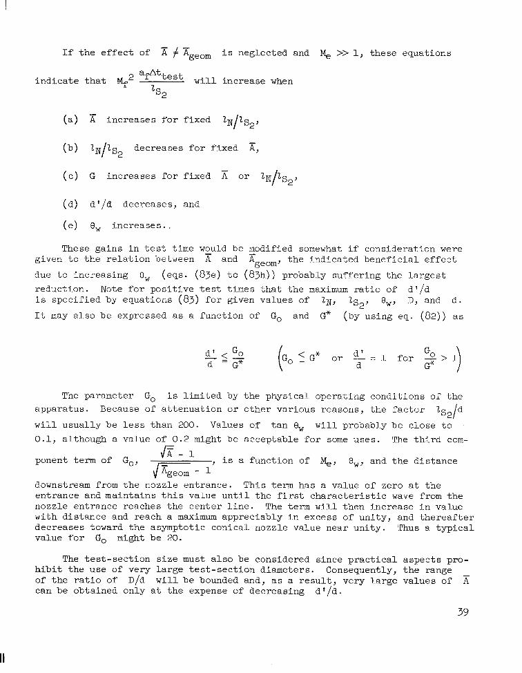
If t h e e f f e c t of x i s neglected and M, >> 1, these equations
a A t
2 i nd ica t e that Mf test w i l l increase when
s2
( a ) A i nc reases fo r f i xed 2 ~ / 2 s ~ , -
( e ) G increases for f ixed A or 2 ~ / 2 s ~ , -
(d) d ' /d decreases, and
( e ) e, increases .
These ga ins i n t e s t t ime would be modified somewhat i f consideration were given t o t h e r e l a t i o n between A and Ageom, the ind ica ted benef ic ia l e f fec t
due to increas ing 8, (eqs. (83e) t o (83h) ) probably suf fe r ing the l a rges t reduction. Note f o r p o s i t i v e t e s t t i m e s t h a t t h e maximum r a t i o of d ' /d i s specified by equations (83) for given values of IN, 2s2, Ow, D, and d .
It may also be expressed as a function of Go and G* (by using eq. (82)) as
- -
The parameter Go i s l imi ted by the physical operating conditions of the apparatus. Because of attenuation or other various reasons, the factor 2S2/d
w i l l usua l ly be l ess than 200. Values of t a n 8, w i l l probably be close to 0.1, although a value of 0 .2 might be acceptable for some uses . The t h i r d com-
ponent term of Go,
downstream from the nozzle entrance. This term has a value of zero a t the entrance and maintains t h i s v a l u e u n t i l t h e f irst c h a r a c t e r i s t i c wave from the nozzle entrance reaches the center l ine. The term w i l l then increase in value with dis tance and reach a maximum appreciably in excess of unity, and t h e r e a f t e r decreases toward the asymptotic conical nozzle value near unity. Thus a t y p i c a l value for Go m i g h t be 20.
6- 1
JG- I- , i s a function of %, e,, and the d i s t ance
The t e s t - sec t ion s i z e must a lso be considered s ince pract ical aspects pro- h ib i t t he u se of very large test-section diameters. Consequently, the range of t h e r a t i o of D/d w i l l be bounded and, as a resul t , very large values of A can be obtained only a t t he expense of decreasing d 'Id.
-
39

Growth of the nozzle boundary layer for the rather low Reynolds numbers of the nozzle i s a l s o a f ac to r fo r cons ide ra t ion . However, o n l y f a i r l y small effective nozzle half-angles are required. Consequently, a t f i r s t g l a n c e t h e problem appears t o be p r inc ipa l ly one of co r rec t ing fo r t he e f f ec t o f dS*/dg a t small 5 , and then a t a l a r g e r 5 expanding f u r t h e r , i f necessary, t o assure a po ten t i a l " co re" a t t he t e s t s ec t ion . Th i s low Reynolds number nozzle problem w i l l require addi t ional s tudy before i t s f u l l e f f e c t can be determined.
Equation (84) i s i n a form which permits evaluation and comparison on a tes t -sect ion-diameter basis which i s s ign i f i can t when considering large A.
-
The va r i a t ion of afattest with Mf i s shown i n f i g u r e 28. Since D -112
" ' - 10A , no curves are drawn f o r A l e s s t h a n 100. The gains with - d
increasing A of Attest a r e l a r g e r when compared on a common tes t - sec t ion- d i ame te r bas i s ( f i g . 28) than on a common accelerating-chamber-length basis. (See f ig . 27.) This statement i s not universally valid but applies under the p rev ious r e s t r i c t ions (a) t o ( a ) .
-
Equation (83e) may be r ewr i t t en fo r M, >> 1 a s
y-l af*ttest "" - 1 ('.2 d x 2 - 1 1 )
D Mf2 D 2 - y t a n e,
Examination of equation (85 ) revea ls the reason tha t the shock tunnel (operating
a t very large A) has a higher value of afAttest than the expansion tunnel -
D
40
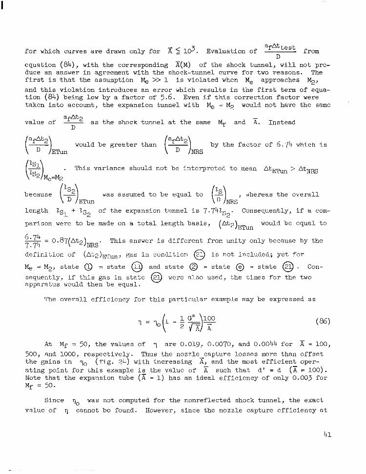
f o r which curves are drawn only for Evaluation of af*tt e st D
from
equation (84), with the corresponding A(M) of t he shock tunnel, w i l l not pro- duce an answer i n agreement with the shock-tunnel curve for two reasons. The f i r s t i s t h a t t h e assumption M, >> 1 i s v io l a t ed when Me approaches M;1, and th i s v io l a t ion i n t roduces an e r ro r which r e s u l t s i n t h e f irst term of equa- t i o n (84) being low by a f a c t o r of 5.6. Even i f this cor rec t ion fac tor were taken into account, the expansion tunnel with M, = M2 would not have the same
value of - afnt2 a s t h e shock t u n n e l a t t h e same Mf and A. Instead -
D
would be greater than - by t he f ac to r of 6.74 which i s (af:2),, ETun
(2)&=M2 . This var iance should not be interpreted to mean &,ETun > AtNRS
because (2) was assumed to be equa l t o , whereas t h e o v e r a l l
l ength 2s1 + 2s2 of the expansion tunnel i s 7.741 . Consequently, i f a com-
parison were t o b e made on a to ta l l ength bas i s , (At2)Emn would be equal to
ETun
s2
" 6'74 - 0.87(At2)ms. This answer i s d i f f e r e n t from unity only because by the 7.74 de f in i t i on of ( A t 2 ) E m , gas in condi t ion @ i s not included; yet for
M, = M;?? s t a t e 0 = s t a t e @J and s t a t e 0 = s t a t e = s t a t e @ . Con- s e q u e n t l y , i f t h i s g a s i n s t a t e @ were also used, the t imes for the two apparatus would then be equal.
The o v e r a l l e f f i c i e n c y f o r th i s p a r t i c u l a r example may be expressed as
A t Mf = 50, the values of 7 a r e 0.019, 0.0070, and 0.0044 f o r x = 100, 500, and 1000, respec t ive ly . Thus the nozzle capture losses more than of fse t t he ga ins i n v0 ( f i g . 24) w i t h increasing A, and the most e f f ic ien t oper - a t i n g p o i n t f o r t h i s example i s the value of such tha t a' = d (A = 100). Note that the expansion tube (K = 1) has an ideal eff ic iency of only 0.003 f o r Mf = 50.
-
Since 7, was not computed for the nonref lected shock tunnel, the exact value of 7 cannot be found. However, s ince the nozzle capture eff ic iency a t
q = 50 i s approximately y lov4, it i s obvious that t h e o v e r a l l eff i - 100 A
ciency i s wel l below the expansion-tunnel values.
Design De ta i l s
The design of the conical nozzles i s an important problem area where a s tudy tha t uses the method of cha rac t e r i s t i c s has been underway for an extended period. The gene ra l r e su l t s of t h i s s tudy are not included here but one par- t i c u l a r c a s e i s i l l u s t r a t e d i n f i g u r e s 29 and 30. The entrance Mach number i s 10 and the primary nozzle angle 8, i s 5 . 3 O . I n an e f f o r t t o r e d u c e t h e noz- z l e lengths ZN, the use of compound or multiple nozzles has also been con- s ide red . Th i s l a t t e r scheme, s i m i l a r t o t h a t used i n shock tunnels ( re fs . 2 and 6 ) , i s shown in ske t ch (b ) . The curves of figure 29 show the cen ter - l ine
Mach number d i s t r i b u t i o n as a function of 2 N / d
nozzle with the imbedded nozz le l ips loca ted 7. for both the simple nozzle and the compound
Imbedded nozzle a t - - d - 12. This imbedded nozzle has an
\ \ entrance radius equal to 0.37d' and a wal l angle of 5 . 6 O The compound nozzle arrange- ment i s successful in shortening the nozzle for
a given Mf f o r example, = 40 a t - 2N = 40 d
Sketch (b)
( 2 N f o r a compound nozzle and a t - - - 7 3 f o r a simple nozzle . However, t h i s 1
reduct ion in 2N i s obtained a t t h e expense of tes t - sec t ion grad ien ts as
shown by the radial d is t r ibut ion of f low angle and Mach number i n f i g u r e 30. The ve loc i ty va r i a t ion i s negl ig ib le s ince the Mach number va r i a t ion i s almost ent i re ly due t o changes i n t h e speed of sound. Values of 6 for source f low wi th v i r tua l o r i - gins a t the nozzle entrances indicate that the f low incl ina- t i o n i s s l i g h t l y worse than t ha t of source flow. For radi- ation experiments where the important contributions arise a t t h e model surfaces most normal to t he f r ee s t r eam, t he v a r i a t i o n i n 8 would probably not be important.
d )
< Sketch ( c )
A pract ical nozzle configurat ion might a lso include a boundary-layer scoop a t t he en t r ance s ec t ion t o ob ta in a
more uniform enter ing veloci ty prof i le . (See sketch (e) . ) The t rade-of f in nozzle performance against this increased complexity has not been explored.
C r i t i c a l Lengths
Accelerating-chamber cr i t ical length.- Since operat ion over a range of Mf and 7i i s des i rab le and the va lues of d and D a re genera l ly f ixed , the
42

nozzle capture diameter d ' w i l l probably be the var iable parameter of an actual expansion tunnel. This variation i s e a s i l y accomplished; f o r example, a reduction i n d ' r e s u l t s from a s l ight forward extension to the nozzle sec- t i o n . Thus the "constant" component dimensions are Z N and D. Expressions re la t ing the c r i t i ca l acce le ra t ion-chamber l ength G 2 f o r which t h e t e s t t i m e
vanishes to these components may be obtained from equations (78), (79), and (80). Thus,
From f igu re 26 a t Mf = 50, c= 0.32 and $ = 0 .47 fo r A = LO3 and -
A A - A = lo2, respectively. Consequently, for these cases - zs2 - - 0.64 and 0.94; and
D s2 - 3.2 and 4.7 ( f o r t a n 8, = 0.1). The crit ical accelerating-chamber length
i s not excessive; therefore , pract ical lengths for do n o t r e s u l t i n l a r g e
percentage of losses in tes t t ime. If i n t h e c a s e s above 2 = 150d = l 5 D ,
the tes t - t ime percentage loss i s - s2 - - - - - 20 percent for A = 103.
2* I N "
lS2
s 2 2" -
lS2 15
Dump-tank length . - From equation ( 6 5 ) and f igu res l 9 (a ) and l 9 ( b ) , it i s ev iden t t ha t t he r a t io ZSR/ ls2 increases with increasing A. Such an increase
i s not a true penalty for expansion-tunnel operation because of the increased t e s t i n g time ava i lab le . For example, by combining equations ( 6 5 ) , (39), (3a), and (la), the fo l lowing re la t ion may be found:
Consequently, on a u n i t t e s t t i m e b a s i s , actual ly decreases with A. O f
course , to u t i l i ze fu l ly the expans ion- tunnel capabi l i t i es the ra t ios f o r
2sR/2s2
2SR -
of equation ( 6 5 ) should be maintained.
43

The perfect-gas analysis of this report has covered many f a c e t s of expansion-tunnel operation. The more important advantages and disadvantages of t h e expansion tunnel compared with the expansion tube are as follows:
Advantages :
(1) The zero-nozzle-length test time (a$t2/ls2) per unit length i s
increased. The t i m e l o s t i n t h e s t a r t i n g and stopping processes of the nozzle i s , in general , only a smal l f rac t ion of t h i s t ime At2 f o r r a t i o s of nozzle length 2~ to accelerating-chamber length 1s2 l e s s t han 112 and f o r l a r g e
-
a r e a r a t i o s A. -
(2) The usab le t e s t s lug l eng th p r io r t o secondary-diaphragm rupture Y+l -
increases rap id ly wi th x and i s roughly proportional to A a t h igh t e s t - sec t ion Mach number %.
- 2
(3) The secondary-diaphragm bursting problem i s greatly reduced.
(4 ) The nondimensional energy parameter E/Afpfafnt2 decreases w i t h
increasing A. Thus the expansion tunnel i s espec ia l ly su i ted to a rc -hea ted d r ive r s . The idea l e f f ic iency a l so increases wi th E .
( 5 ) The primary diaphragm i s of smaller diameter for the same t e s t - sec t ion a rea Af and consequently t h i s b u r s t i n g problem i s also reduced.
(6) The low pressure in the acce le ra t ing chamber pll i s s ign i f i can t ly
higher. A s a consequence, e i t h e r t h e pumping capacity could be reduced and/or t he same gas a s t he t e s t gas might be used t o reduce interface mixing effects.
(7) The dump-tank length parameter 2sR/afAt2 i s reduced.
(8) Viscous effects may be reduced for nozzle entrance diameter less than accelerating-chamber diameter (d' < d ) .
Disadvantages:
(1) Fairly long nozzles are required. The (theoretical) expansion tube f l e x i b i l i t y o f v a r i a b l e Mach number MY without nozzle changes i s l o s t . How- ever, conical nozzles might be employed t o r e g a i n t h i s f l e x i b i l i t y w i t h small flow gradients. The e f f e c t of nozzle boundary-layer growth must also be considered.
( 3 ) The r a t i o of the minimum charging pressure in the dump t a n k t o t h e tes t - sec t ion pressure plo/pf i s decreased and thus requires increased pumping
capacity.
(4) A t h i r d diaphragm i s added to appara tus .
( 5 ) The length parameters ZD/ZS2, Zs1/ZS2, and 2sR/2s2 a l l increase
with a as w e l l a s 2Sl/a&t2 and zD/afAt2 where Z D i s the d r iver l ength ,
2s1, the intermediate-chamber length, 2sR, t h e dump-tank length, and af i s
speed of sound i n t e s t s e c t i o n . However, f o r l a r g e Mf, t h e l e n g t h 2 i s
s t i l l by far t h e predominant l eng th as long as > lo3. s2
In the opinion of the authors, the advantages of the expansion tunnel appea r , pa r t i cu la r ly i n t he l i gh t of practical operating problems, to outweigh the disadvantages.
Langley Research Center, National Aeronautics and Space Administration,
Langley Station, Hampton, V a . , February 2, 1965.
REFERENCES
1. Trimpi, Robert L . : A Preliminary Theoretical Study of the Expansion Tube, a New Device f o r Producing High-Enthalpy Short-Duration Hypersonic Gas Flows. NASA TR R-133, 1962.
2. Hertzberg, A. ; Smith, W. E . ; Glick, H. S . ; and Squire, W.: Modifications of t h e Shock Tube for the Generat ion of Hypersonic Flow. AEDC-TN-55-15 (~D-789-A-2)~ Arnold Eng. Dev. Center, Mar. 1955.
3. Ames Research Staff: Equations, Tables, and Charts for Compressible Flow. NACA Rept . 1135, 1953. (Supersedes NACA TN 1428. )
4. Glick, H. S.; Hertzberg, A . ; and Smith, W. E. : Flow Phenomena i n S t a r t i n g a Hypersonic Shock Tunnel. Rept. No. AD-789-A-3 (AEDC-TN-55-16), Cornell Aero. Lab., Inc . , Mar. 1955.
5 . Knoos, S t e l l an : A Theoretical and Experimental Study of t h e Opening of t h e Low-Pressure Diaphragm i n a Double-Diaphragm Shock Tube. Thesis, Roy. I n s t . of Technol. (Stockholm), 1963.
6 . Hertzberg, A . : The Shock Tunnel and I t s Applications to Hypersonic Flight. Rep. No. AD-1052-A-5 ( A F O S R - T N - ~ ~ - ~ ~ ~ , AD-126567), Cornell Aero. Lab., Inc . , June 1957.
46

TABLE 1.- INDEX TO FIGURES
Figure
Schematic and wave diagram f o r expansion tunnel . . . . . . . . . . . . . . . . . . . . . . . . . . 1 Variation of conditions at nozzle 'entrance with test-section Mach number . . . . . . . . . . . . . 2
(a) Speed-of-sound r a t i o . (b) Flow-velocity ratio; (c) Stat ic-pressure ra t io . (a) Nozzle-entrance Mach number.
(b) Flow-velocity ratio. ( a ) Speed-of-sound r a t i o .
(c) Stat ic-pressure ra t io . (a) Reciprocal total-enthalpy ratio.
( a ) Mach number. (b) Area r a t i o .
Variation of conditions i n region @ with tes t -sect ion Mach number . . . . . . . . . . . . . . . . 3
Variation of parameter p with Mach number and a rea r a t io . . . . . . . . . . . . . . . . . . . . . 4.
Variation of primary shock velocity parameter with test-section M a c h n u m b e r . . . . . . . . . . . . . . . . . . . . . . . . . . . . . . . . . . . . . . . . . . 5
Variation of i n i t i a l intermediate-chamber density ratio with test-section Mach number . . . . . . 6 Init ial accelerating-chamber pressure ratio parameter for 1 = - Dump-tank charging pressure parameter for perfect nozzle start . . . . . . . . . . . . . . . . . . 8
a 49 5 144' Yll = 7 . . . . . . . . . . 7
( a ) 710 = 711 = 1-4.
( c ) rlO = rll = -. 5 3
Dump-tank absolute charging pressure for perfect nozzle s tar t . . . . . . . . . . . . . . . . 9 Unsteady waves generated by entropy discontinuity flowing through nozzle . . . . . . . . . . . . . 10
(a) Schematic of wave system. ( b ) Wave diagram. (c) Pressure-velocity diagram.
Pressure ratio across waves generated by passage of entropy discontinuity between @ and @ through nozzle . . . . . . . . . . . . ' . . . . . . . . . . . . . . . . . . 11
(a) rll = 1.4. 5
( b ) Y u = 5' Driver pressure ratio for helium driver gas at various temperatures . . . . - * * * * * 12
( a ) - = 10. '1'4
' Tf
( c ) - = 50. *4 T f
Wave diagram i l lus t ra t ing nozz le s ta r t ing p rocesses and r e s u l t i n g t e s t time . . . . . . . . . . . 13 Zero-nozzle-length test time parameters for expansion tunnel and nonreflected
shock t u n n e l . . . . . . . . . . . . . . . . . . . . . . . . . . . . . . . . . . . . . . . . . . 14
In tegra ls In and Jn f o r 7 = 5 with 7 and lower limit M, = 1 . . . . . . . . . . . . . . . . . . . 15 3 5 (a ) 11. (b) 12.
47

TABLE I.- INDEX TO FIGURES - Concluded
Figure
16
17 18 19
Effect of nozzle length on loss of test time for linear area nozzle . . . . . . . . . . . . . . . Ratio of nozzle time losses in linear-radius nozzle compared with those in linear-area
Ratio of intermediate-chamber length to accelerating-chamber length . . . . . . . . . . . . . . . nozzle . . . . . . . . . . . . . . . . . . . . . . . . . . . . . . . . . . . . . . . . . . . . Ratio of dump-tank length to accelerating-chamber length . . . . . . . . . . . . . . . . . . . .
(a) 710 = 5; 711 =
(b) rlO = 711 - *
5 7 5
5 3
Ratio of driver length to intermediate-chamber length for helium driver. r4 = - . . . . . . . . 5 3
(a) - = 10. T4 Tf T4 Tf
T4
(b) - = 25.
(e) - = 50. T,
Ratio of driver length to accelerating-chamber length for helium driver. 7 4 = 5 . T 4 = 2 5 . . . . 3' Tf
Ratio of initial length of test gas slug to accelerating-chamber length. 1~ = 0 . . . . . . . . Variation of driver energy parameter with test-section Mach number for helium-driven
expansion tunnels . . . . . . . . . . . . . . . . . . . . . . . . . . . . . . . . . . . . . .
20
21
22
23
(e) - T4 = 50. Tf
Ideal efficiency of helium-driven expansion tunnels. - T4 = 25 . . . . . . . . . . . . . . . . . . Tt 24
Ratios of Reynolds numbers and nondimensional boundary-layer thicknesses in accelerating and test chambers for case d' = d . . . . . . . . . . . . . . . . . . . . . . . . . . . . . . . .
Variation of values of parameter G* for conical nozzles . . . . . . '. . . . . . . . . . . . . . . 25 26 (a) With Mach number.
(b) With area ratio.
Effect of G on test time parameter - &@%est 2s
. . . . . . . . . . . . . . . . . . . . . . . . . . . Variation of test time parameter %%& with test-section Mach
D
27
2 number for numerical example. Conical nozzle; $ = $; 52 = 150; and Go = 20 . . . . . . . .
Mach number variation along center line of simple conical nozzle and compound conical nozzle with distance from nozzle entrance. M, = 10; ow = 5 .3O . . . . . . . . . . . . . . . .
Radial variation of flow Mach number and inclination . . . . . . . . . . . . . . . . . . . . . .
28
29 30
Accelerating chamber
/
Shock wave
Characteristics "" Particle path
n
. . "
c ~
Distance, x
Figure I.- Schematic and wave diagram for expansion tunnel.
49

4. e
4.2
3. E
3.4
3. c
2. 6
2.2
1.8
1. 4
1.0
I
.._.___I" I I
Equation (2)
-. ~ Equation (2a) I I
1 20 30 40
Test-section Mach number, iV$
~~
(a) Speed-of-sound ratio.
A
1000 - -
500 - -
100 - -
50 - 25 --
lo - -
_1 60
Figure 2- Variat ion of condi t ions at nozzle entrance wi th test-sect ion Mach number.

1.0
C . C
. 8
. 7
.6
I_cL_ 7 . \ \ A
10 20 30 40
Test-section Mach number, Mf
(b) Flow-velocity ratio.
Figure 2.- Continued.
50
20
. . ..
Test-section Mach number, Mf
. "
- A
1000
500
100
50
25
10
1
- .
"
"
"
___ .. "
"
1 BO 70
(c) Static-pressure ratio.
Figure 2- Continued

70
60
50
40
30
20
10
. c
i . ..-.
Equation (1)
- - Equation (la)
. -
I .= I. - I".
/ /
.o 20 30 40 50 60 70 Test-section Mach number, Mf
(dl Nozzle-entrance Mach number.
Figure 2- Concluded.
53
12
10
8
6
4
2
0 I
500
100 50 25 10 1
"I . . . . . . .
I " 1 -___ .-
. ~ ! ! . - ."
20 30 40
Test-section Mach number, Mf
(a) Speed-of-sound ratio.
Figure 3.- Var iat ion of coridit ions in region @with test-section Mach number.
50 60
54
. ._. .. I _ . .
1.0
. 9
. 8
c)
Q, 3 3 . 6
. L F
.4
c . \ 10
- A
30 40 50 Test-section Mach number, Mf
(b) Flow-velocity ratio.
Figure 3.- Continued
55
- A
1000 500 .- 100 50 - 25 10 1
lo5
lo4
103
102
101
100 0 10 20 30 40
Test-section Mach number, ktf
. . . .
. . . . .
50 GO
(c) Stat ic-pressure rat io.
F igu re 3.- Continued.

A cd 0 c,
c,
. .~ 7
1 20 1 30
Test-section Mach number,
- A
1
10 25 50 100
500 1ooc
60
(d l Reciprocal total-enthalpy ratio.
Figure 3.- Concluded.
57
P
1. 6
1.5
1. 4
1.3
1. 2
1.1
Equation 1
- - "Equation I "t-
"1 L
10 20 30 40 5G Test-section Mach number, Mf
A
1000
500
100 50
25 10
1
(a) Mach number.
Figure 4.- Variation of parameter p with Mach number and area ratio.
2.0"1 Equation (14)
I
- - - Equation (17) !
1.6! I
P i ,
1.4' /
1.0 10
Mf
100 Nozzle area ratio, ?i
1000
(b) Area ratio.
Figure 4.- Concluded.
24
20
16
12
8
4
. .
0 10
".
20 30 40 Test-section Mach number, Mf
50
1000 500 100 50 25 "- IO 1
60
Figure 5.- Var iat ion of primary shock velocity parameter with test-section Mach number.
60
10
10 4
c- .- lo
10 -
C 10
10 -
- "
_- .
10 < L
. .
..
. . _ _
i I i "
"
"
" - 1 40
Test-section Mach number, lVif
Figure 6.- Variation of initial intermediate-chamher density ratio with test-section Mach number.
61

10
20 30 Test-section Kach number, IL.,
"----- 5
A - -
1000
500 "
~
100 --
I_
50
10
1
i
Figure 7. - Initial accelerating-chamber pressure ratio parameter for - = -, y - al 49 5 a 144 11 - 3' 11
62

10-51 0 10 20
Test-section Mach number, Mf 40 50
(a) yl0 = y l l = 1.4.
F igu re 8. - Dump-tank charging pressure parameter for perfect nozzle start
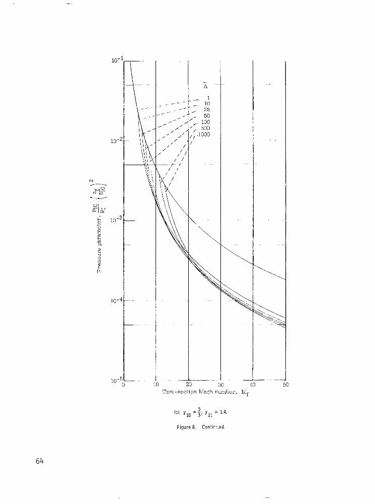
30 40 50 Test-section Mach number, Mi
64

I
10-
10 -
10"
10"
10 -
10-
. ".
0 10 20
\
..
30 40 50
'Test-section Mach number, Mf
". ..
-
- H
1
10 25 50 100
500 too0
. ". . " .
.. .
" " - 60 70
5 (c) Yl0 = Y l l = 3.
Figure 8.- Concluded.
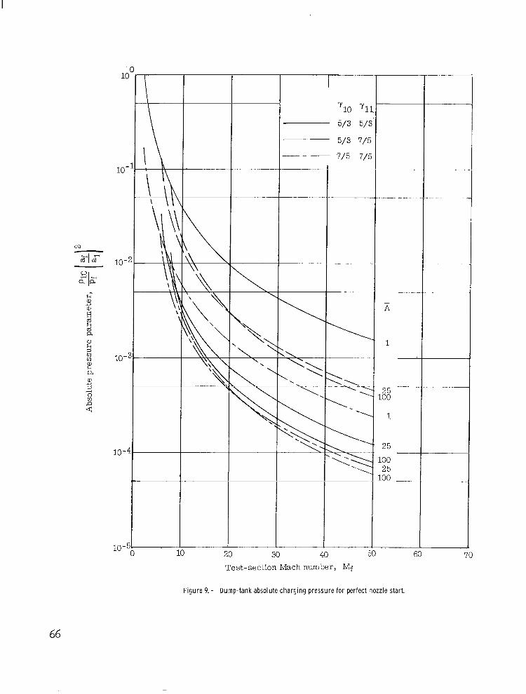
10 (
10 -
10-4
3
I 5 0 y1:
5/3 5/:
".
20 30 40 50 60 70 Test-section Mach number, Mf
Figure 9. - Dump-tank absolute charging pressure for perfect nozzle start.
66

(a) Schematic of wave system.
State
E- (b) Wave diagram.
t P
0 g 5-0 u -
(c) Pressure-velocity diagram.
Figure 10.- Unsteady waves generated by entropy discontinuity f lowing through nozzle.
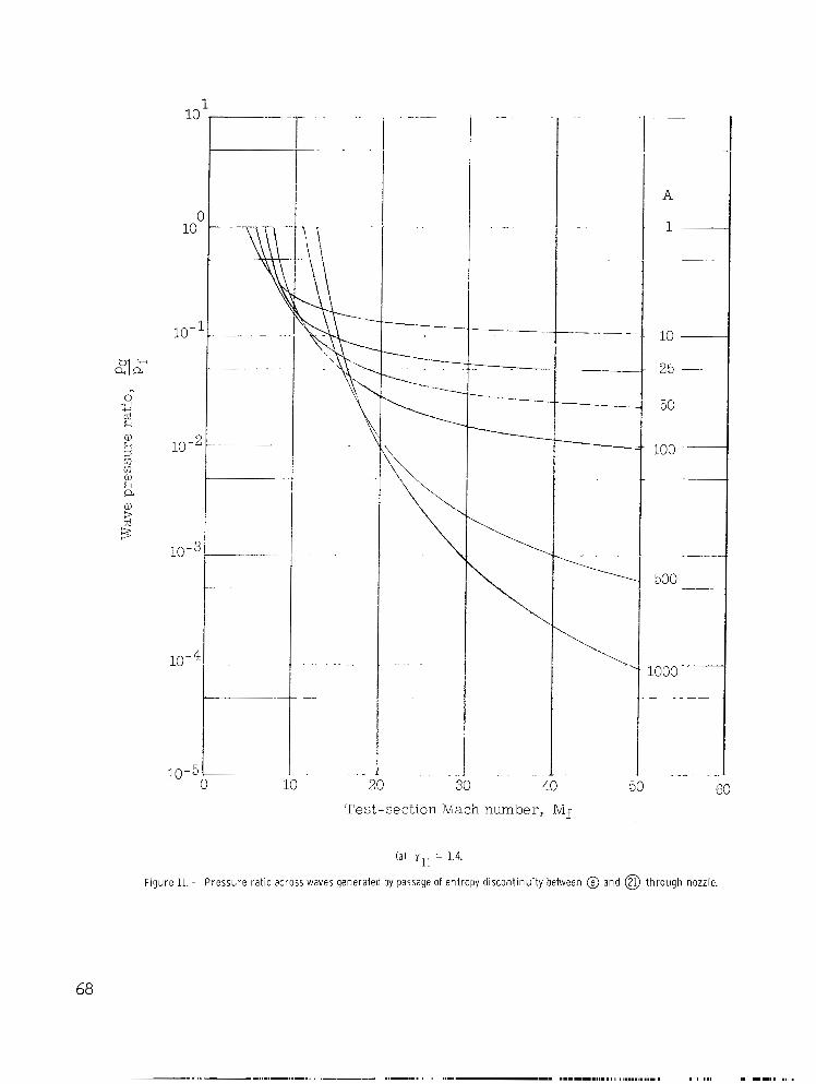
lo-'
32 .rl i"
0
E
10 -4
" . . . . .
. . . . . . . . .
"
'-"" . . . .
. "
"
A
1
-~
10
25
50
100
500
1000 "
10 20 30 40 50 60 Test-section Mach number, n/If
(a) y l l = 1.4.
F igure 11. - Presshre rat io across waves generated by passage of entropy discont inui ty between @ and @) through nozzle.
68

10- A
10-2
10-6
10- E
10-7
. "--\
"'\
. .
I
1
\ . ..
100 50
20 30 4 0 Test-section Mach number, n/if
. _
LO -
-
I
- 1 4-
I " 50
5 (b) y l l = 7.
Figure 11.- Concluded.

30 40 50
Test-section Mach number, Mf
GO
l 4 Tf
(a) - = 10.
F igu re 12. - Dr i ve r p ressu re ra t i o f o r he l i um d r i ve r gas at var ious temperatures.
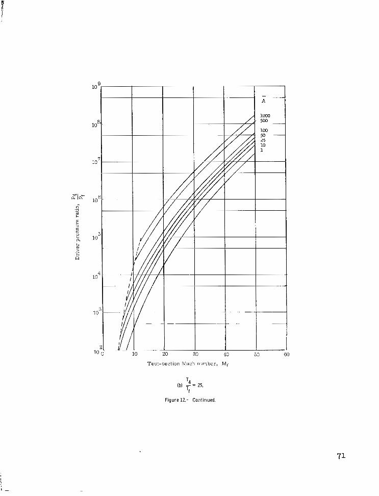
Test-section Mach number, NIf
T4
Tf (b) - = 25.
Figure 12.- Continued.

I"
10
Test-sectic
" . - . 40
In Mach number, Mf 60
T4
Tf (c) - = 50.
Figure 12- Concluded.

0
Figurel3.- Wave diagram i l lustrat ing nozzle start ing processes and resul t ing test t ime.
73
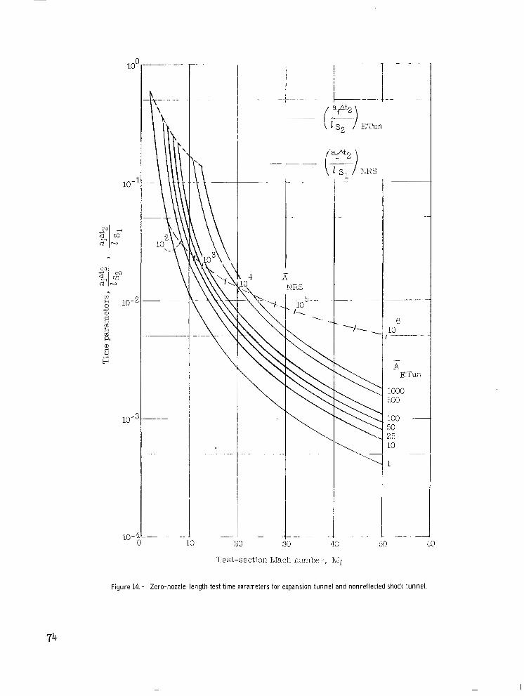
id'j ETun
/,"fat2 - - '"
KRS
I
.
- 1
6 10
~
- A E:
1000 500
100 50 25 10
1
"
I 20 30 40 50 UO
Test-section hvlach mmber, Ibif
Figure 14. - Zero-nozzle-length test time parameters for expansion tunnel and nonreflected shock tunnel.
74

I.
loL
10 2
10 '
10 0
10-1
10-2
Test-section Mach number, Mf
3
Figure 15.- Integrals In and Jn for y = - and - with lower limit Me = 1. 3 5 5 7 .
75
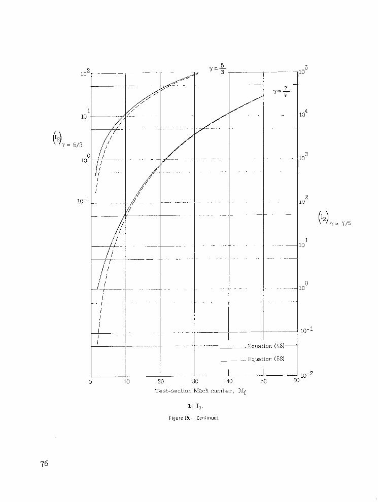
10 1 20 30 110
Test-section Mach number, Mf
50
.o 5
lo4
3 .o
2 to
H Y = 7/5
1 -0
0 .o
10-1
.I 10-2 60
(b) I p .
Figure 15.- Continued.
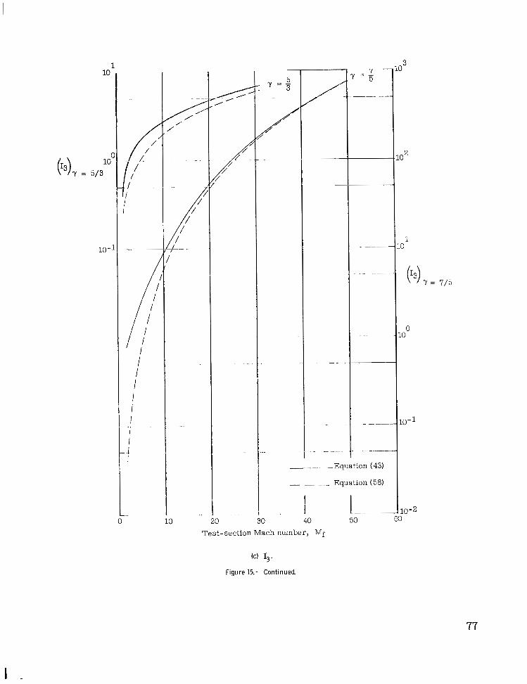
10 20 30
___. . -Equation (
- - __ Equation (
I I- 40
O2
1
0 0
10-2
Test-section Mach number, Mf
(c) 13.
Figure 15.- Continued.
77
I

10'
10'
10-1
0 10
// /
- y = 5/3-
"
Equation ( 5 6 )
- . .. . - Equation (59)
20 30 40
Test-section Mach number, Mf
50
10 4
10
10
10 0
10-
(dl J1/2.
Figure 15.- Continued.

Equr
- - .- Equation (59)
40
10 2
10 1
(J3/2) Y = 7/5
Test-section Mach number, Mf
(e) J3I2. Figure 15.- Continued.
79

__7L
I I
f
0 10 20 30 40 Test-section Mach number, Mf
Equation (56)
Equation (59)
.o 1
"12) ' y=7/5
.oo
.o -
( f ) J5/2.
Figure 15.- Concluded.

I
Exact ETun
- NRS (eq. (61))
I
- "- Approximate ETun (eq. (60))
A
- , --- . - ~ 10
;"F-: &/". . ._ - . . .
" - - "-"
I" ..-I."
- . - 30
10
25
- 1 500
."
I 50
Test-section Mach number, i'v$
Figure 16.- Effect of nozzle length on loss of test t ime for l inear area nozzle.
81

02
I
t .
".
c\3 . . . ."
4
4 4 4
- . ..
"-
~~ . . .
. "i \\ 0 ' 4
- ai N N 0 c m E m L m m c .- - .- c m v) 0 5 ._ 5

13 ?
10'
1oc
10- 1
10-2
10-3 4
- A
1000
500
~
~
100
50
25 __
10
50 f Test-section Mach number, Mf
Figure 18. - Ratio of intermediate-chamber length to accelerating-chamber length.

C . L
. 8
. 7
.6
.5
.4
. 3
.2
.1
i i I 1
Test-section Mach number, Mf
Figure 19. - Ratio of dump-tank length to accelerating-chamber length.
0
84

\
10 20 30 40 50 Test-section Mach number, Mf
60
(b) yl,, = y I 1 = 3. 5
Figure 19.- Concluded.
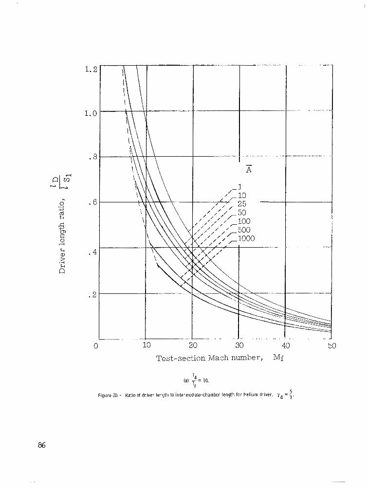
1.2
1.0
.8
n
0 .6 .d 4
k .4 .d s &
.2
0
\ \ \
L- \
\
"
T - A
10 20 30 40 Test-section Mach number, Mf
T4
Tf (a) - = 10.
Figure 20. - Ratio of driver length to intermediate-chamber length for helium driver. Y 4 = 5 . 5
50

2.0
1.6
. 4
0
\ \
r 1 ,’ r 10
10 20 30 40 Test -section Mach number, Mf
50
T4
Tf (b) - = 25.
Figure 20.- Continued.
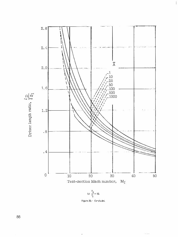
2.8
2.4
2.0
1. E
.d 4
0
cd k 1.2
.4
0
. " - " ".
10 20 30 40 Test-section Mach number, Mf
- . . . . , .". .
50
T4
Tf (c) - = 50.
Figure 20.- Concluded.
88
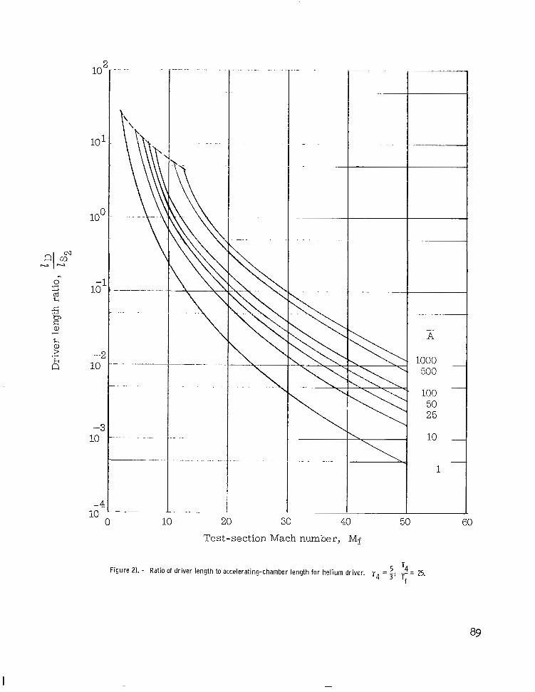
10'
10
loc
10. -
c
10 - c
-c:
10
-4
- . ."
. . . .
.. - I . . . . . .
. . . . . .
. .
...
...............
10 20 30 40 50
Test-section Mach number, Mf
- A
1000 500
100 50 25
60
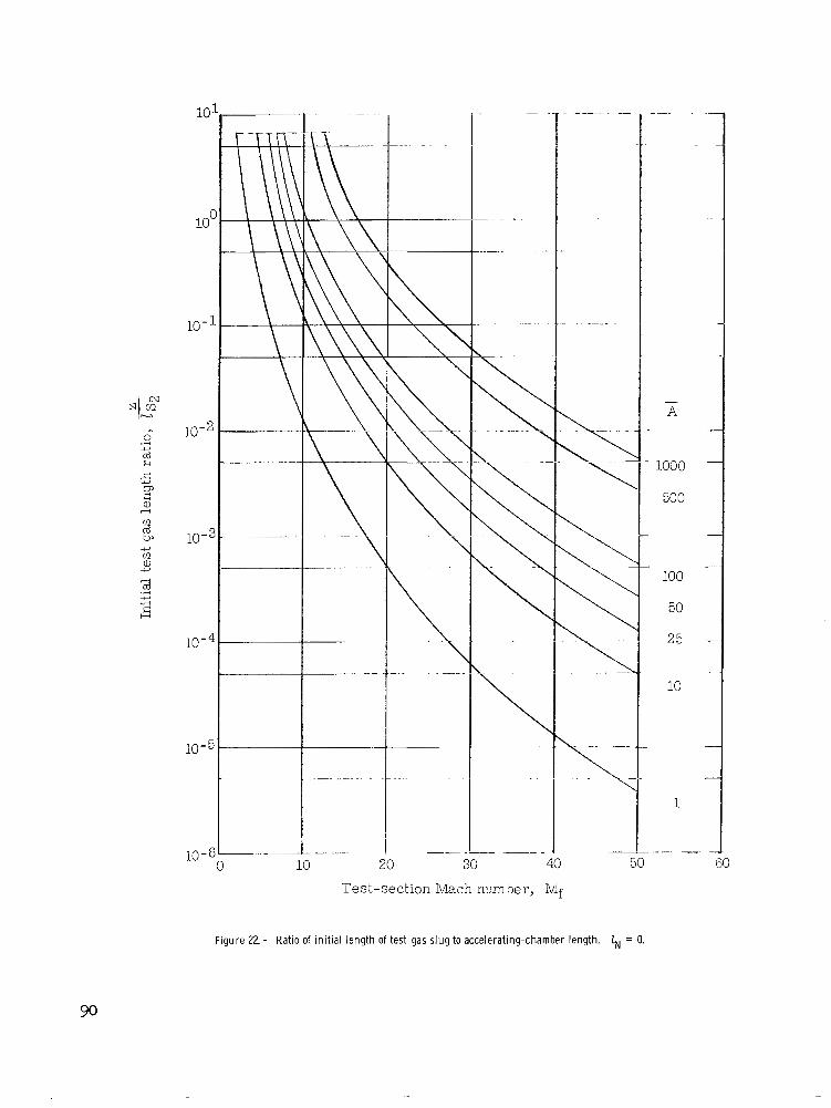
." . . .
-
" . 10-60 u 10 20 30 Test-section Mach number, Mf
". . .
- A
- 1000
500
100
50
25
10
1
.-
F igu re 22. - Ratio of initial l eng th of test gas slug to accelerat ing-chamber length. 6 = 0.
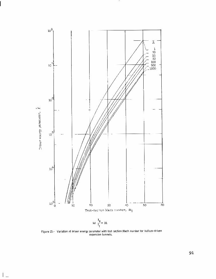
10 7
loE
IL4
lo4
10 20 30 40 50 60
Test-section Mach number, Nlf
T4
Tf fa) - = 10.
Figure 23.- Variation of driver energy parameter with test-section Mach number for helium-driven expansion tunnels.

.
10 20 30 40 Test-section Mach E m b e r , Mf
B
1
10
25 50 100
500 1000
. .
~.
"
' 4
Tf (b) -= 25.
Figure 23.- Continued.

I
I I 40 !
Test-section Mach number, Mf
T4
Tf (c) - = 50.
Figure 23.- Concluded.
- A
1
10 25
50 100
500 1000
93

10 -
0 c
_ . i 10
\
20
* \ \ \
Test-section Mach number, Mf
li \
E
Figure 24.- Ideal efficiency of helium-driven expansion tunnels. T4
Tf - = 25.
- A
1000
50 0
100
50
25
10
1
94

I”
1 -
-
o d - 0
95

14
12
1c
e
E
4
2
"-
k =F" l__"."
30 L
Test-section Mach number, Mf
- A 1
/ N R S
A
1000
-
500
100
50
25
10
-1
(a) Wi th Mach number.
Figure 26.- Var iat ion of values of parameter G* for conical nozzles.

I
12
10
8
G" ETun
6
4
2
C
- . . . . . . . . .
. . . - . . . .
. . . . .
. . . . . . . "
Nozzle area ratio, A
(bl With area ratio.
Figure 26.- Concluded.
97

1c I
10 -
1 100 1000
"- -
NRS . . . . . . . . .
t- " I . "
G
. . . 9 . . 9 . . . . . . s
s 9
" - 9
9 .
\
10 - t ". ?"-
\ \
4 9
* 1c
I.
\ 100
\
\ \ ! \ 10 I
30 40 10" I -0 L
20 1 60 1
Test-section Mach number, Mf
Figure 27.- Effect of G on test time parameter -. afAttest 1s

J
ETun (exact)
NRS " - ETun (approx. ) ~. - .~
5 v 10
'\
+& \ I
Test-section Mach number, h$
T
- i
+ \
a i
5c
I -I
"
.~
6 P
- A
1000 500
100
3
a At Figure 28.- Variation of test time parameter __ Fst with test-section Mach number for
numer ica l example. Conical nozzle; - = - - 's,' - - 150; Go = M. D 10'
99

I ' I
~ __ - _" Imbedded nozzle . Single-stage nozzle
I "_+I___ ?' # Ldcation of imbedded nozzle
I I
I 20 40 69 80 I( 120
Distance from nozzle entrance, t /d '
Figure 29.- Mach number var ia t ion a long center l ine of simple conical nozzle and compound conical nozzle. Me = 10; 8, = 5.3 0 .
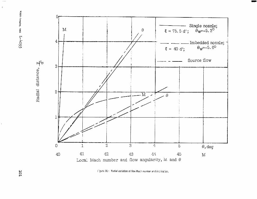
T F F P '<
E
4
1
M Single nozzle; I , 0 f = 75. 5 df ; e,=-5.3'
1 2 3 4 5
41 42 43 44 45 Local Mach number and flow angularity, M and 0
Figure 30.- Radial variation of flow Mach number and inclination.
" T h e aeronautical and space actiuities of the United States shall be conducted so as to contsibute . . . t o the expansion of human knowl- edge of phenomena i n the atmosphere and space. The Administration shall provide for the widest practicable aud appropride dissemination of information concerning its activities and the results thereof.''
" N A T I O N A L AERONAUTKS AND SPACE ACT OF 1958
NASA SCIENTIFIC AND TECHNICAL PUBLICATIONS
TECHNICAL REPORTS: Scientific and technical information considered important, complete, and a lasting contribution to existing knowledge.
TECHNICAL NOTES: Information less broad in scope but nevertheless of importance as a contribution to existing knowledge.
TECHNICAL MEMORANDUMS: Information receiving limited distri- bution because of preliminary data, security classification, or other reasons.
CONTRACTOR REPORTS: Technical information generated in con- nection with a NASA contract or grant and released under NASA auspices.
TECHNICAL TRANSLATIONS: Information published in a foreign language considered to merit NASA distribution in English.
TECHNICAL REPRINTS: Information derived from NASA activities and initially published in the form of journal articles.
SPECIAL PUBLICATIONS: Information derived from or of value to NASA activities but not necessarily reporting the results .of individual NASA-programmed scientific efforts. Publications include conference proceedings, monographs, data compilations, handbooks, sourcebooks, and special bibliographies.
Details on the availability o f these publications may be obtained from:
SCIENTIFIC AND TECHNICAL INFORMATION DIVISION
NATIONAL AERONAUTICS AND SPACE ADMINISTRATION
Washington, D.C. 20546