Embed Size (px)
Citation preview
Transmitters
Electron Pumps
that convert
DC Power into
AC Power
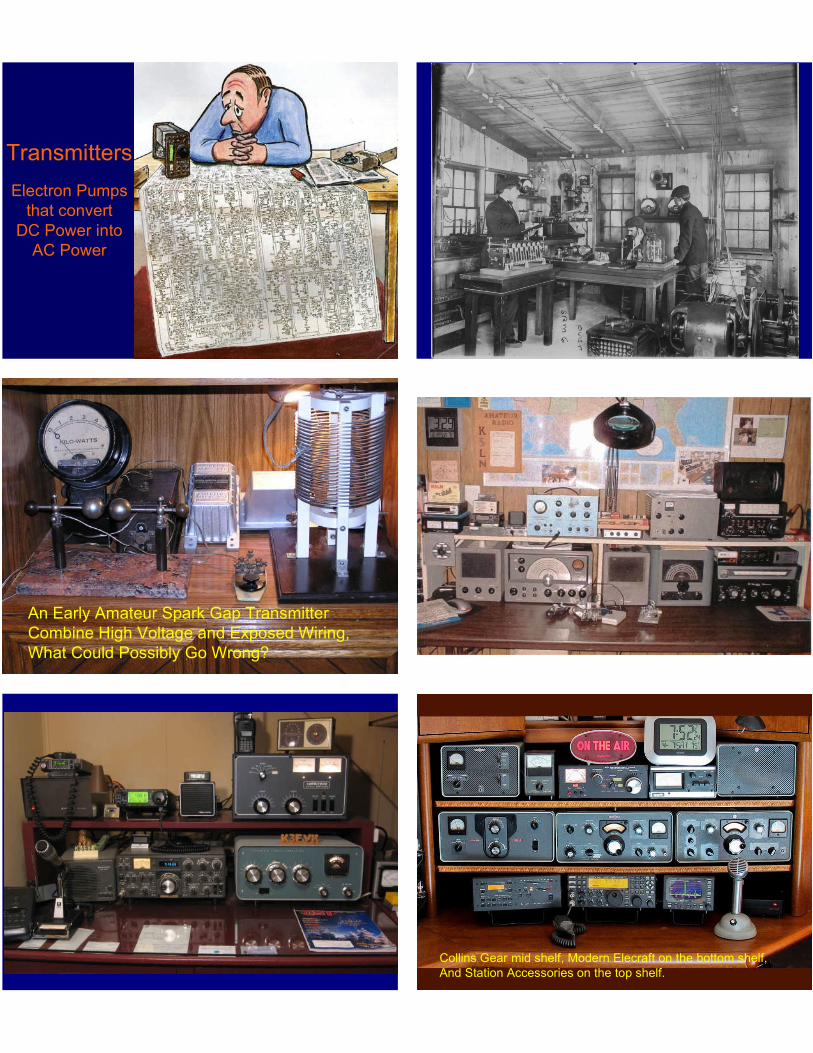
An Early Amateur Spark Gap Transmitter
Combine High Voltage and Exposed Wiring,
What Could Possibly Go Wrong?
Collins Gear mid shelf, Modern Elecraft on the bottom shelf,
And Station Accessories on the top shelf.
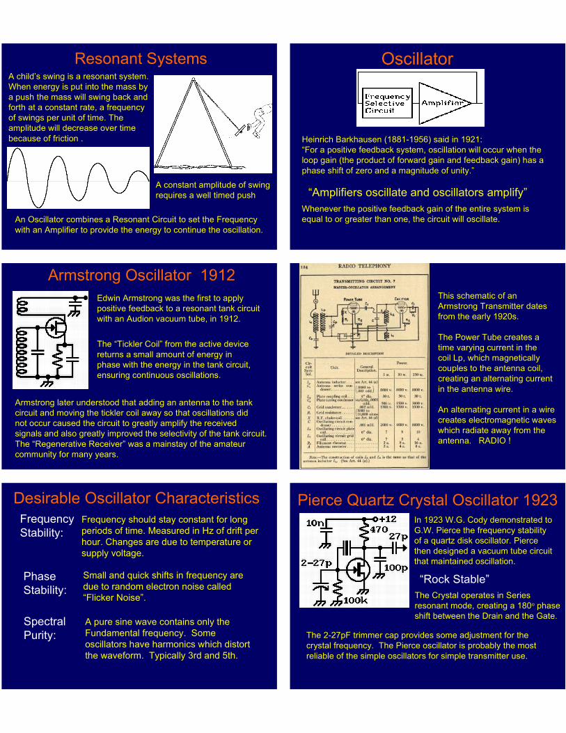
Resonant SystemsA child’s swing is a resonant system.
When energy is put into the mass by
a push the mass will swing back and
forth at a constant rate, a frequency
of swings per unit of time. The
amplitude will decrease over time
because of friction .
A constant amplitude of swing
requires a well timed push
An Oscillator combines a Resonant Circuit to set the Frequency
with an Amplifier to provide the energy to continue the oscillation.
Heinrich Barkhausen (1881-1956) said in 1921:
“For a positive feedback system, oscillation will occur when the
loop gain (the product of forward gain and feedback gain) has a
phase shift of zero and a magnitude of unity.”
“Amplifiers oscillate and oscillators amplify”
Whenever the positive feedback gain of the entire system is
equal to or greater than one, the circuit will oscillate.
Oscillator
Armstrong Oscillator 1912
Edwin Armstrong was the first to apply
positive feedback to a resonant tank circuit
with an Audion vacuum tube, in 1912.
The “Tickler Coil” from the active device
returns a small amount of energy in
phase with the energy in the tank circuit,
ensuring continuous oscillations.
Armstrong later understood that adding an antenna to the tank
circuit and moving the tickler coil away so that oscillations did
not occur caused the circuit to greatly amplify the received
signals and also greatly improved the selectivity of the tank circuit.
The “Regenerative Receiver” was a mainstay of the amateur
community for many years.
This schematic of an
Armstrong Transmitter dates
from the early 1920s.
The Power Tube creates a
time varying current in the
coil Lp, which magnetically
couples to the antenna coil,
creating an alternating current
in the antenna wire.
An alternating current in a wire
creates electromagnetic waves
which radiate away from the
antenna. RADIO !
Desirable Oscillator Characteristics
Spectral
Purity:
Phase
Stability:
Frequency
Stability:
Frequency should stay constant for long
periods of time. Measured in Hz of drift per
hour. Changes are due to temperature or
supply voltage.
Small and quick shifts in frequency are
due to random electron noise called
“Flicker Noise”.
A pure sine wave contains only the
Fundamental frequency. Some
oscillators have harmonics which distort
the waveform. Typically 3rd and 5th.
Pierce Quartz Crystal Oscillator 1923In 1923 W.G. Cody demonstrated to
G.W. Pierce the frequency stability
of a quartz disk oscillator. Pierce
then designed a vacuum tube circuit
that maintained oscillation.
“Rock Stable”
The Crystal operates in Series
resonant mode, creating a 180o phase
shift between the Drain and the Gate.
The 2-27pF trimmer cap provides some adjustment for the
crystal frequency. The Pierce oscillator is probably the most
reliable of the simple oscillators for simple transmitter use.
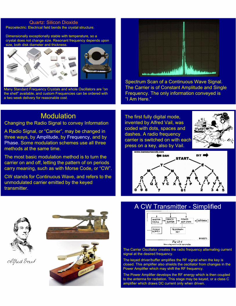
Quartz: Silicon DioxidePiezoelectric: Electrical field bends the crystal structure.
Dimensionally exceptionally stable with temperature, so a
crystal does not change size. Resonant frequency depends upon
size, both disk diameter and thickness.
Many Standard Frequency Crystals and whole Oscillators are “on
the shelf” available, and custom Frequencies can be ordered with
a two week delivery for reasonable cost.
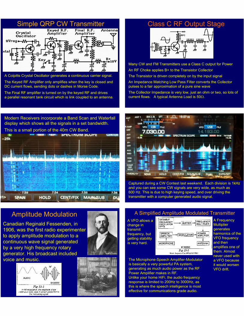
Spectrum Scan of a Continuous Wave Signal.
The Carrier is of Constant Amplitude and Single
Frequency. The only information conveyed is
“I Am Here.”
ModulationChanging the Radio Signal to convey Information
A Radio Signal, or “Carrier”, may be changed in
three ways, by Amplitude, by Frequency, and by
Phase. Some modulation schemes use all three
methods at the same time.
The most basic modulation method is to turn the
carrier on and off, letting the pattern of on periods
carry meaning, such as with Morse Code, or “CW”.
CW stands for Continuous Wave, and refers to the
unmodulated carrier emitted by the keyed
transmitter.
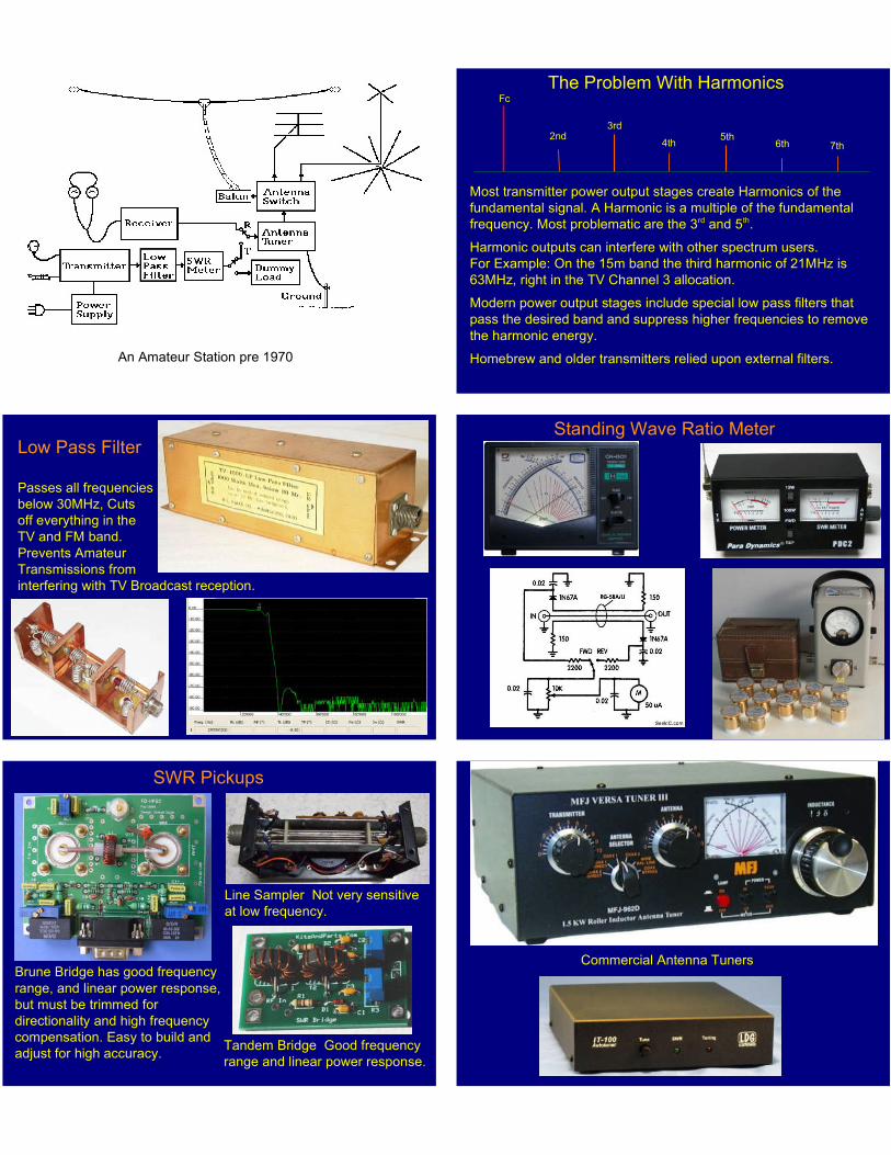
The first fully digital mode,
invented by Alfred Vail, was
coded with dots, spaces and
dashes. A radio frequency
carrier is switched on with each
press on a key, also by Vail.
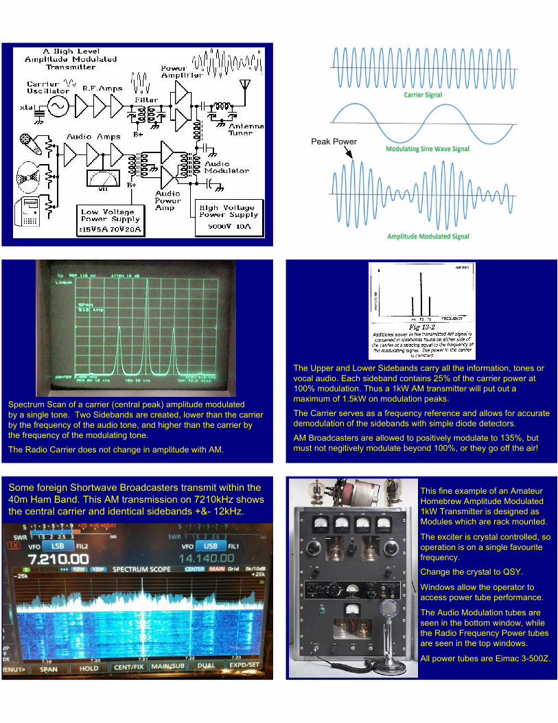
A CW Transmitter - Simplified
The Carrier Oscillator creates the radio frequency alternating current
signal at the desired frequency.
The keyed driver/buffer amplifies the RF signal when the key is
closed. This amplifier also shields the oscillator from changes in the
Power Amplifier which may shift the RF frequency.
The Power Amplifier develops the RF energy which is then coupled
to the antenna for radiation. This stage may be keyed, or a class C
amplifier which draws DC current only when driven.
A Colpitts Crystal Oscillator generates a continuous carrier signal.
The Keyed RF Amplifier only amplifies when the key is closed and
DC current flows, sending dots or dashes in Morse Code.
The Final RF amplifier is turned on by the keyed RF and drives
a parallel resonant tank circuit which is link coupled to an antenna.
Simple QRP CW Transmitter
Class C RF Output Stage
RFC
Many CW and FM Transmitters use a Class C output for Power
An RF Choke applies B+ to the Transistor Collector
The Transistor is driven completely on by the input signal
An Impedance Matching Low Pass Filter converts the Collector
pulses to a fair approximation of a pure sine wave
The Collector Impedance is very low, just an ohm or two, so lots of
current flows. A typical Antenna Load is 50W.
Modern Receivers incorporate a Band Scan and Waterfall
display which shows all the signals in a set bandwidth.
This is a small portion of the 40m CW Band.
W
J
U
ST
R
E
Captured during a CW Contest last weekend. Each division is 1kHz
and you can see some CW signals are very wide, as much as
600 Hz. This is due to high keying speed, and over driving the
transmitter with a computer generated audio signal.
Amplitude Modulation
Canadian Reginald Fessenden, in
1906, was the first radio experimenter
to apply amplitude modulation to a
continuous wave signal generated
by a very high frequency rotary
generator. His broadcast included
voice and music.
A Simplified Amplitude Modulated Transmitter
A VFO allows a
change in
transmit
frequency, but
getting stability
is very hard.
A Frequency
Multiplier
generates
harmonics of the
VFO frequency
and then
amplifies one of
them. Almost
never used with
a VFO because
it would worsen
VFO drift.
The Microphone-Speech Amplifier-Modulator
is basically a very powerful PA system,
generating as much audio power as the RF
Power Amplifier makes in RF.
Unlike your home HiFi, the audio frequency
response is limited to 200Hz to 3000Hz, as
this is where the speech intelligence is most
effective for communications grade audio.
Peak Power
Spectrum Scan of a carrier (central peak) amplitude modulated
by a single tone. Two Sidebands are created, lower than the carrier
by the frequency of the audio tone, and higher than the carrier by
the frequency of the modulating tone.
The Radio Carrier does not change in amplitude with AM.
The Upper and Lower Sidebands carry all the information, tones or
vocal audio. Each sideband contains 25% of the carrier power at
100% modulation. Thus a 1kW AM transmitter will put out a
maximum of 1.5kW on modulation peaks.
The Carrier serves as a frequency reference and allows for accurate
demodulation of the sidebands with simple diode detectors.
AM Broadcasters are allowed to positively modulate to 135%, but
must not negitively modulate beyond 100%, or they go off the air!
Some foreign Shortwave Broadcasters transmit within the
40m Ham Band. This AM transmission on 7210kHz shows
the central carrier and identical sidebands +&- 12kHz.
This fine example of an Amateur
Homebrew Amplitude Modulated
1kW Transmitter is designed as
Modules which are rack mounted.
The exciter is crystal controlled, so
operation is on a single favourite
frequency.
Change the crystal to QSY.
Windows allow the operator to
access power tube performance.
The Audio Modulation tubes are
seen in the bottom window, while
the Radio Frequency Power tubes
are seen in the top windows.
All power tubes are Eimac 3-500Z.
An Amateur Station pre 1970
The Problem With Harmonics
Most transmitter power output stages create Harmonics of the
fundamental signal. A Harmonic is a multiple of the fundamental
frequency. Most problematic are the 3rd and 5th.
Harmonic outputs can interfere with other spectrum users.
For Example: On the 15m band the third harmonic of 21MHz is
63MHz, right in the TV Channel 3 allocation.
Modern power output stages include special low pass filters that
pass the desired band and suppress higher frequencies to remove
the harmonic energy.
Homebrew and older transmitters relied upon external filters.
Fc
2nd3rd
4th5th
6th 7th
Low Pass Filter
Passes all frequencies
below 30MHz, Cuts
off everything in the
TV and FM band.
Prevents Amateur
Transmissions from
interfering with TV Broadcast reception.
Standing Wave Ratio Meter
SWR Pickups
Brune Bridge has good frequency
range, and linear power response,
but must be trimmed for
directionality and high frequency
compensation. Easy to build and
adjust for high accuracy.
Line Sampler Not very sensitive
at low frequency.
Tandem Bridge Good frequency
range and linear power response.
Commercial Antenna Tuners
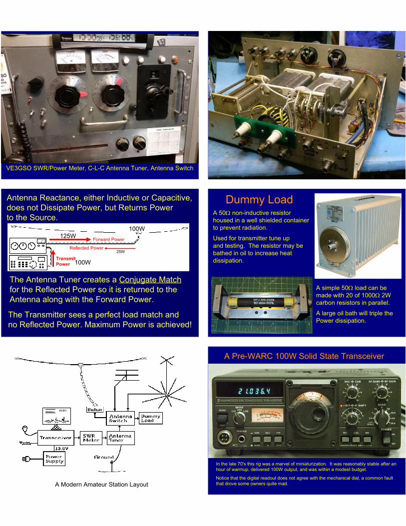
VE3GSO SWR/Power Meter, C-L-C Antenna Tuner, Antenna Switch
Antenna Reactance, either Inductive or Capacitive,
does not Dissipate Power, but Returns Power
to the Source.
Forward Power
Reflected Power
The Antenna Tuner creates a Conjugate Match
for the Reflected Power so it is returned to the
Antenna along with the Forward Power.
The Transmitter sees a perfect load match and
no Reflected Power. Maximum Power is achieved!
Transmit
Power 100W
25W
125W100W
Dummy LoadA 50W non-inductive resistor
housed in a well shielded container
to prevent radiation.
Used for transmitter tune up
and testing. The resistor may be
bathed in oil to increase heat
dissipation.
A simple 50W load can be
made with 20 of 1000W 2W
carbon resistors in parallel.
A large oil bath will triple the
Power dissipation.
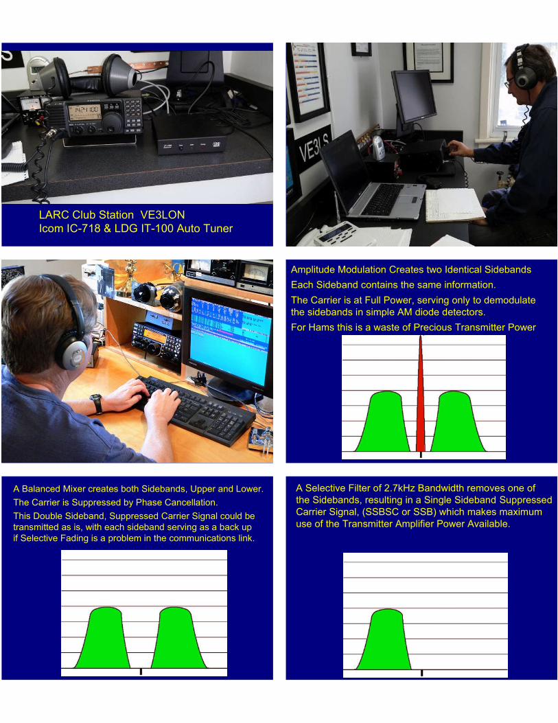
A Modern Amateur Station Layout
A Pre-WARC 100W Solid State Transceiver
In the late 70's this rig was a marvel of miniaturization. It was reasonably stable after an
hour of warmup, delivered 100W output, and was within a modest budget.
Notice that the digital readout does not agree with the mechanical dial, a common fault
that drove some owners quite mad.
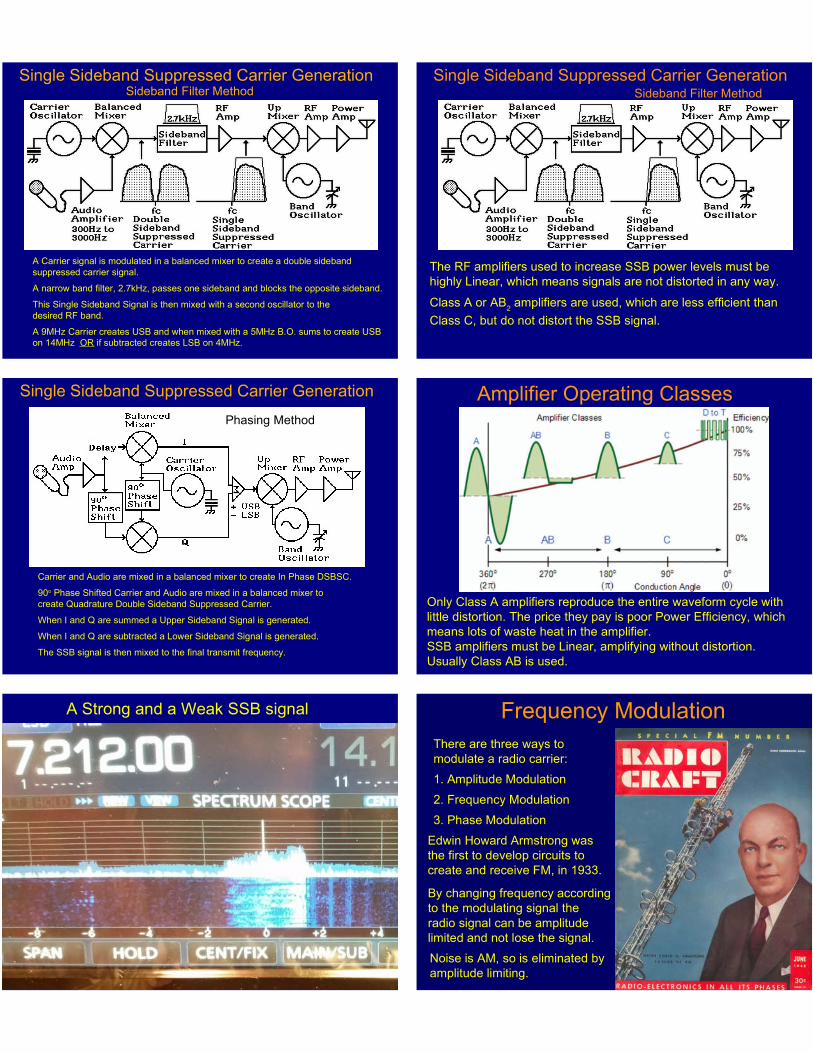
LARC Club Station VE3LON
Icom IC-718 & LDG IT-100 Auto Tuner
Amplitude Modulation Creates two Identical Sidebands
Each Sideband contains the same information.
The Carrier is at Full Power, serving only to demodulate
the sidebands in simple AM diode detectors.
For Hams this is a waste of Precious Transmitter Power
A Balanced Mixer creates both Sidebands, Upper and Lower.
The Carrier is Suppressed by Phase Cancellation.
This Double Sideband, Suppressed Carrier Signal could be
transmitted as is, with each sideband serving as a back up
if Selective Fading is a problem in the communications link.
A Selective Filter of 2.7kHz Bandwidth removes one of
the Sidebands, resulting in a Single Sideband Suppressed
Carrier Signal, (SSBSC or SSB) which makes maximum
use of the Transmitter Amplifier Power Available.
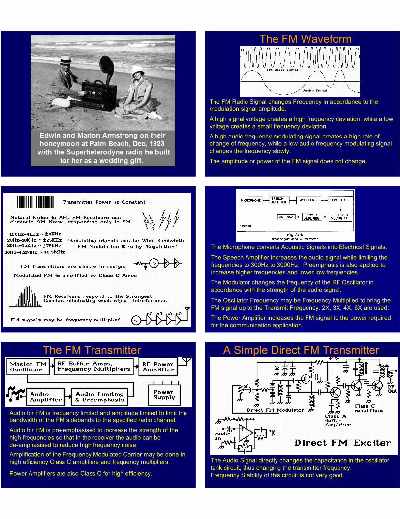
Single Sideband Suppressed Carrier GenerationSideband Filter Method
A Carrier signal is modulated in a balanced mixer to create a double sideband
suppressed carrier signal.
A narrow band filter, 2.7kHz, passes one sideband and blocks the opposite sideband.
This Single Sideband Signal is then mixed with a second oscillator to the
desired RF band.
A 9MHz Carrier creates USB and when mixed with a 5MHz B.O. sums to create USB
on 14MHz OR if subtracted creates LSB on 4MHz.
Single Sideband Suppressed Carrier GenerationSideband Filter Method
The RF amplifiers used to increase SSB power levels must be
highly Linear, which means signals are not distorted in any way.
Class A or AB2 amplifiers are used, which are less efficient than
Class C, but do not distort the SSB signal.
Single Sideband Suppressed Carrier Generation
Phasing Method
Carrier and Audio are mixed in a balanced mixer to create In Phase DSBSC.
90o Phase Shifted Carrier and Audio are mixed in a balanced mixer to
create Quadrature Double Sideband Suppressed Carrier.
When I and Q are summed a Upper Sideband Signal is generated.
When I and Q are subtracted a Lower Sideband Signal is generated.
The SSB signal is then mixed to the final transmit frequency.
Amplifier Operating Classes
Only Class A amplifiers reproduce the entire waveform cycle with
little distortion. The price they pay is poor Power Efficiency, which
means lots of waste heat in the amplifier.
SSB amplifiers must be Linear, amplifying without distortion.
Usually Class AB is used.
A Strong and a Weak SSB signal
Frequency Modulation
There are three ways to
modulate a radio carrier:
1. Amplitude Modulation
2. Frequency Modulation
3. Phase Modulation
Edwin Howard Armstrong was
the first to develop circuits to
create and receive FM, in 1933.
By changing frequency according
to the modulating signal the
radio signal can be amplitude
limited and not lose the signal.
Noise is AM, so is eliminated by
amplitude limiting.
The FM Waveform
The FM Radio Signal changes Frequency in accordance to the
modulation signal amplitude.
A high signal voltage creates a high frequency deviation, while a low
voltage creates a small frequency deviation.
A high audio frequency modulating signal creates a high rate of
change of frequency, while a low audio frequency modulating signal
changes the frequency slowly.
The amplitude or power of the FM signal does not change.
The Microphone converts Acoustic Signals into Electrical Signals.
The Speech Amplifier increases the audio signal while limiting the
frequencies to 300Hz to 3000Hz. Preemphasis is also applied to
increase higher frequencies and lower low frequencies.
The Modulator changes the frequency of the RF Oscillator in
accordance with the strength of the audio signal.
The Oscillator Frequency may be Frequency Multiplied to bring the
FM signal up to the Transmit Frequency. 2X, 3X, 4X, 6X are used.
The Power Amplifier increases the FM signal to the power required
for the communication application.
The FM Transmitter
Audio for FM is frequency limited and amplitude limited to limit the
bandwidth of the FM sidebands to the specified radio channel.
Audio for FM is pre-emphasised to increase the strength of the
high frequencies so that in the receiver the audio can be
de-emphasised to reduce high frequency noise.
Amplification of the Frequency Modulated Carrier may be done in
high efficiency Class C amplifiers and frequency multipliers.
Power Amplifiers are also Class C for high efficiency.
A Simple Direct FM Transmitter
The Audio Signal directly changes the capacitance in the oscillator
tank circuit, thus changing the transmitter frequency.
Frequency Stability of this circuit is not very good.
Terms Definition
Deviation: The amount of frequency shift of the radio carrier to
either side of the Centre Frequency. eg: +&- 5kHz
Centre Frequency: The carrier frequency of the transmitter without
any modulating audio. eg: 147.06 MHz
Modulation Index: The ratio of the Carrier Deviation to the
Frequency of the Modulating Signal.
M.I. = Deviation / Modulating Frequency
Deviation Ratio: Peak Deviation / Highest Modulating Frequency
eg: 5kHz / 3kHz = 1.666
FM noise suppression improves with higher Deviation Ratio.
Frequency Modulated Sidebands
As the full strength radio carrier deviates in frequency it deposits
power across a wide band of frequencies, in direct accordance
with the modulating signal amplitude and frequency.
A FM Radio Carrier is much wider than a similar AM signal, but
noise immunity and higher fidelity is worth it. FM radio is best
suited to higher frequency bands where bandwidth is available.
At a Modulation Index of 2.4 the carrier disappears with all
transmitter power contained in the sidebands. A Bissell Null.
At some Modulating frequency and deviation, all the carrier
power is in the sidebands and the carrier frequency is empty.
Freq
Time
A Carrier Frequency Modulated by a swept frequency signal
Phase Modulation
A Sine Wave can be thought of as a Vector Rotating Counter-
Clockwise, with one full rotation in one Cycle.
The Length of the Vector represents the amplitude of the signal.
The Number of full rotations in one second is the Frequency.
The position in Degrees away from the 0 position at any moment
is the phase of the signal at that moment.
PSK - Phase Shift Keying
BPSK - Binary Phase Shift Keying
QPSK - Quadrature Phase Shift Keying
O-QPSK - Offset Quadrature Phase Shift Keying
8 PSK - 8 Point Phase Shift Keying
16 PSK - 16 Point Phase Shift Keying
QAM - Quadrature Amplitude Modulation
16 QAM - 16 Point Quadrature Amplitude Modulation
64 QAM - 64 Point Quadrature Amplitude Modulation
256 QAM - 256 Point Quadrature Amplitude Modulation
MSK - Minimum Shift Keying
GMSK - Gaussian filtered Minimum Shift Keying
Multiple PSK Modulation Schemes
Binary Phase Shift Keying
This 180o Phase Shift encodes a change of state from a 0 to 1 or
a 1 to 0. The phase shift occurs at the zero crossover.
PSK-31 uses a phase shift at 31 symbols per second to provide
reliable communications at low power.
Phase Modulation
An instantaneous change of position of the Vector, in Binary PSK
a 180 degrees phase shift, modulates two data bits: 0 and 1.
Multiple Phase Positions and Amplitudes are possible. In
Quadrature PSK two bits are sent at a time using four phases.
Each Separate Position means a different symbol, so that
a simple phase change can communicate multiple Bits, such
as in 8PSK, where three bits are sent at a time.
Modern Digital Communication Modes
Amateur Radio is fortunate to have many knowledgeable and
generous members who utilize their skills to create Software that is
freely available to everyone for the Digital Mode of choice.
A USB connected MODEM (Modulator-Demodulator) creates the
Audio Tones that encode the computer data for transmission by any
SSB transceiver.
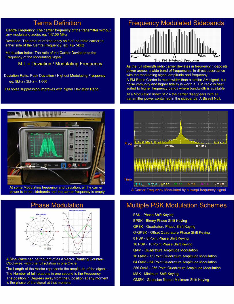
Olivia, PSK31, PSK63, Pactor, FT-8, RTTY, WSPR, SSTV, MFSK,
Throb, Hellschreiber, Field Hell, DV, Packet, Contesta, JT65M, Thor,
Domino, MT63, HamDRM, Digital SSTV, etc.
www.hfradio.org.uk/html/digital_modes.html
PSK31 is a digital communications mode ideal for live
keyboard-to-keyboard conversations, similar to
radioteletype.
Concept proposed by Pawel, SP9VRC and developed
completely by Peter Martinez, G3PLX
Data rate is 31.25 bauds (about 50 word-per-minute),
with narrow bandwidth (approximately 60 Hz at -26 dB)
reduces its susceptibility to noise, and ideal for QRP.
It uses BPSK modulation without error correction or
QPSK modulation with error correction:
PSK31
PSK-31 Phase Shift Keying
The 31 Bit Per Second data is used to PSK-modulate
an audio "carrier" where phase "shifts" 180 degrees
when the following bit is the same as the previous bit,
and does not shift when the following bit is different from
the previous bit.
0 1 0 0 1 0 0 1 0 0 1 0
FT-8 Frankie Taylor 8 Tones
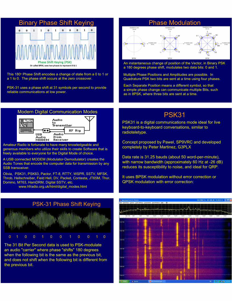
JT65-HF Dr. Joe Taylor