Embed Size (px)
Citation preview

A PARALLEL HYBRID-ELECTRIC SPORT UTILITY VEHICLE—
FUTURETRUCK 2003
FINAL REPORT SEPTEMBER 2003
KLK325
NIATT Report N03-06
Prepared for
OFFICE OF UNIVERSITY RESEARCH AND EDUCATION U.S. DEPARTMENT OF TRANSPORTATION
Prepared by
NATIONAL INSTITUTE FOR ADVANCED TRANSPORTATION TECHNOLOGY UNIVERSITY OF IDAHO
Donald Blackketter, PhD
Frank Albrecht

EXECUTIVE SUMMARY ...................................................................................................... 1
DESCRIPTION OF PROBLEM............................................................................................... 2
APPROACH AND METHODOLOGY ................................................................................... 3
Vehicle Design and Development ........................................................................................ 3 Vehicle Configuration ....................................................................................................................................3 Fuel Selection .................................................................................................................................................4 Engine Selection.............................................................................................................................................5 Hybrid Configuration .....................................................................................................................................6 Electrical System Component Selection.........................................................................................................6 Hydraulic System Component Selection ........................................................................................................7 Hybrid Operating Modes ................................................................................................................................9 Passive Cooling System..................................................................................................................................9 Emissions Control System............................................................................................................................10 Computer Controlled Engine Cooling ..........................................................................................................11 Vacuum Packed Catalytic Converters ..........................................................................................................12 Water Injection .............................................................................................................................................12 Custom Exhaust............................................................................................................................................12 Telematics System........................................................................................................................................13 Vehicle Modeling .........................................................................................................................................16
Student Team ...................................................................................................................... 18 Business Case ...............................................................................................................................................19 Outreach .......................................................................................................................................................20
Findings............................................................................................................................... 22 Test Results ..................................................................................................................................................22 Tailpipe Emissions .......................................................................................................................................22 Fuel Economy...............................................................................................................................................27 Competition Results .....................................................................................................................................27
CONCLUSION....................................................................................................................... 29
A Parallel Hybrid-Electric Sport Utility Vehicle—FutureTruck 2002 i

EXECUTIVE SUMMARY
This final report details the development of the University of Idaho hybrid-electric, hybrid-
hydraulic sport utility vehicle FutureTruck 2003 along with an overview of requirements,
design features and results.
The objectives of the University of Idaho FutureTruck project were to:
• Research and implement clean vehicle technologies that reduce the impact of
transportation on the environment.
• Educate students and provide them with practical experience.
• Increase awareness and support of clean vehicle initiatives and progress.
The University of Idaho Advanced Vehicle Concepts Team (AVCT) developed a unique
hybrid vehicle while simultaneously hosting a series of public relations activities to highlight
the vehicle’s potential for decreasing toxic emissions and improving fuel economy. The team
designed and then built a mild, parallel hybrid vehicle that improved fuel economy by using
stored energy to help the internal combustion engine accelerate the vehicle from rest. By
utilizing electrics and hydraulics, the team captured, stored and re-used energy that is wasted
in a conventional vehicle. A passive cooling system further improved the vehicle’s efficiency
by reducing the amount of energy required to cool the engine and passenger compartment.
Computer-controlled engine cooling and water injection decreased tailpipe emissions while
the use of E85 fuel helped reduce greenhouse gas emissions. A telematics system enhanced
vehicle control and analysis of vehicle performance. Test results showed a 41 percent
improvement in fuel economy and reductions of all regulated emissions. The telematics
system earned a second place at competition for best design.
A Parallel Hybrid-Electric Sport Utility Vehicle—FutureTruck 2002 1

DESCRIPTION OF PROBLEM
FutureTruck 2003 was a challenge to 15 top North American universities to reengineer a
Ford Explorer Sport Utility Vehicle (SUV) for at least 25 percent higher fuel economy and
reduced emissions without compromising performance, utility, safety, and affordability. The
project required modeling to predict performance, written reports to document design details,
and testing to verify concepts. Dynamic testing and static design events were scheduled for
Ford’s Michigan Proving Ground and emissions testing would take place at Ford’s Allen
Park Test Laboratory.
In addition to the objectives set forth by FutureTruck, AVCT goals required the vehicle make
use of current technology, be highly functional in the regional mountainous environment, and
be readily adaptable to high volume manufacturing.
The audience for education and outreach would have no boundaries. While primarily an
engineering project, the team benefited from a diverse and multidisciplinary approach that
included participation from students in subjects such as business, communications, and the
environment. Although the UI campus is located in a rural area of the Pacific Northwest, the
Internet would allow global connections for information exchange and increasing awareness
about clean vehicle initiatives.
A Parallel Hybrid-Electric Sport Utility Vehicle—FutureTruck 2002 2

APPROACH AND METHODOLOGY
Our approach was to focus on engineering, education, and evaluation as related to the
vehicle, team and community. We employed an engineering approach adhering to
professional ethics and proven problem solving methods. We focused on education by
forming diverse student teams that trained one another while applying classroom lessons to
the practical aspects of vehicle design and development. In addition, the team educated the
community through a series of public relations events and written reports. The team also
spent time learning and applying principles of quality management. The team considered ISO
9001 guidelines in optimizing their business of producing an innovative concept vehicle for
the future.
Vehicle Design and Development
The design and development process, detailed at http://www.its.uidaho.edu/PDM, provided a
structured yet insightful approach to solving the problem of building an improved SUV.
Primary areas for improvement included fuel economy and emissions and important related
factors included performance, utility, safety and affordability. The overall design concept
was a mild, hybrid vehicle with a downsized internal combustion engine, passive cooling,
specialized controls, and a telematics system. The following sections describe how these
features were designed and developed.
Vehicle Configuration
The team decided to venture away from the standard of a parallel high-voltage hybrid and
focus on a mild hybrid configuration. Since the high voltage avenue has already been
explored and already put into production in multiple vehicles, AVCT felt that it was more in
the spirit of FutureTruck to pursue technology that is more emergent. This led to considering
low-voltage electrics utilizing ultra-capacitors and hydraulic systems as two methods for
storing energy. Rather than limit the design to a single technology, the team decided to
integrate both on a single vehicle. This approach provided a unique testbed for validating
A Parallel Hybrid-Electric Sport Utility Vehicle—FutureTruck 2002 3

computer model predictions about the efficiency and effectiveness of hybrid-electric and
hybrid-hydraulics. With the use of custom controls, each technology could be tested
individually on the same day and on the same vehicle or both technologies could be tested
together.
Fuel Selection
For fuel, the team chose E85—85 percent ethanol and 15 percent gasoline—as the optimum
fuel for our application. Argonne’s fuel-cycle model GREET (Greenhouse gases, Regulated
Emissions, and Energy use in Transportation) influenced our choice. This model accounts not
only for the energy consumed in procuring and processing the fuel, but includes the
renewability of the fuel source as a factor as well. E85, with a high oxygen content, burns
more completely than gasoline, contains 80 percent fewer gum forming compounds, and
reduces greenhouse gas emissions by nearly 30 percent.
Special modifications were required to utilize the chosen fuel of E85. Since ethanol is more
corrosive then regular gasoline, certain materials (aluminum, brass, silicon) cannot be used.
All of the fuel lines and fittings were replaced with stainless steel: the o-rings are Vinton, and
sealants Teflon. These components ensured there would be no fuel leaks and contamination.
Ethanol has less energy per volume then gasoline (1 gallon of E-85 equals 72 gallons of
gasoline). Since the engine does not have the option of being reprogrammed, the fuel
injectors were replaced by injectors with 40 percent more capacity and are ethanol
compatible. This higher capacity ensures that the same amount of energy in available to the
internal combustion engine.
A Parallel Hybrid-Electric Sport Utility Vehicle—FutureTruck 2002 4

Engine Selection
The internal combustion engine (ICE) is the heart of the vehicle and careful consideration
was taken in its selection. To avoid incompatibility issues with the Explorer and its on-board
control system, the team considered engines solely from Ford and its subsidiaries. Since
space is limited in the Explorer’s engine compartment, only compact engines were evaluated.
For an engine-to-engine comparison, the emissions, fuel economy, and size were normalized.
The emissions were compared by the product of the power and the vehicles mass divided by
the average mass of emissions generated. For a valid emissions comparison, data published
by the Environmental Protection Agency was used. To normalize the fuel efficiency of the
engines, the rated fuel economy was divided by the vehicle mass and engine power. The
engine size was evaluated by dividing the engine power by the displacement. For a direct
hybrid-to-hybrid comparison the Toyota Prius was included. Table 1 shows the normalized
factors for the engines considered.
Table 1 Engines Considered and Overall Ranking
Normalized to EXPLORER 4WD
2001 Carline Liter kW kpl/(kg-kW) Avg kW-kg/emis kW/L Ranking
City 1.474 1.574 Escape 4WD 3.0 149
Hwy 1.546 1.706
1 4.102
City 1.000 1.000 Explorer 4WD 4.0 157
Hwy 1.000 1.000
.7 2.746
City 1.331 0.967 Lincoln LS
3.0 153
Hwy 1.494 1.337
1 3.541
City 1.569 .581 Mazda MILLENIA 2.3 157
Hwy 1.729 .857
1.3 3.686
City 3.346 .467 Mazda MX-5 MIATA 1.8 116
Hwy 3.249 .445
1.2 4.953
City 14.912 6.310 PRIUS
1.5 52
Hwy 10.209 6.443
.7 19.603
A Parallel Hybrid-Electric Sport Utility Vehicle—FutureTruck 2002 5
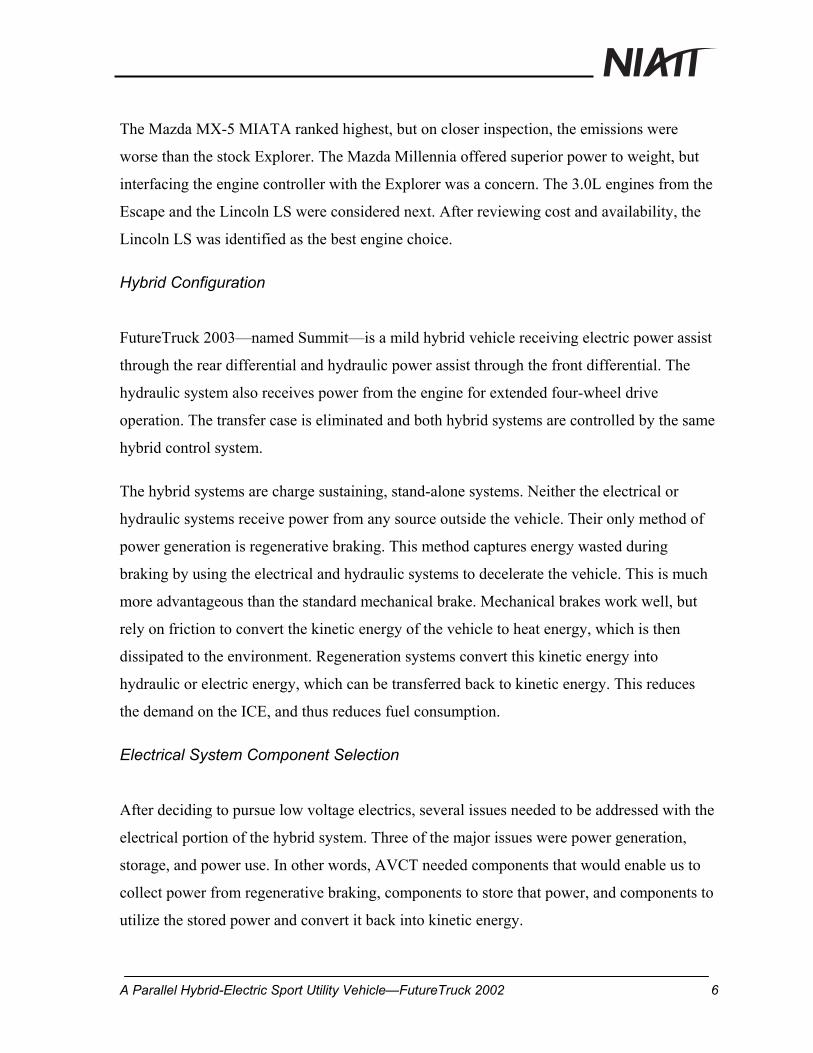
The Mazda MX-5 MIATA ranked highest, but on closer inspection, the emissions were
worse than the stock Explorer. The Mazda Millennia offered superior power to weight, but
interfacing the engine controller with the Explorer was a concern. The 3.0L engines from the
Escape and the Lincoln LS were considered next. After reviewing cost and availability, the
Lincoln LS was identified as the best engine choice.
Hybrid Configuration
FutureTruck 2003—named Summit—is a mild hybrid vehicle receiving electric power assist
through the rear differential and hydraulic power assist through the front differential. The
hydraulic system also receives power from the engine for extended four-wheel drive
operation. The transfer case is eliminated and both hybrid systems are controlled by the same
hybrid control system.
The hybrid systems are charge sustaining, stand-alone systems. Neither the electrical or
hydraulic systems receive power from any source outside the vehicle. Their only method of
power generation is regenerative braking. This method captures energy wasted during
braking by using the electrical and hydraulic systems to decelerate the vehicle. This is much
more advantageous than the standard mechanical brake. Mechanical brakes work well, but
rely on friction to convert the kinetic energy of the vehicle to heat energy, which is then
dissipated to the environment. Regeneration systems convert this kinetic energy into
hydraulic or electric energy, which can be transferred back to kinetic energy. This reduces
the demand on the ICE, and thus reduces fuel consumption.
Electrical System Component Selection
After deciding to pursue low voltage electrics, several issues needed to be addressed with the
electrical portion of the hybrid system. Three of the major issues were power generation,
storage, and power use. In other words, AVCT needed components that would enable us to
collect power from regenerative braking, components to store that power, and components to
utilize the stored power and convert it back into kinetic energy.
A Parallel Hybrid-Electric Sport Utility Vehicle—FutureTruck 2002 6

The charging system consists of three Zena Series 200 generators. These are configured in
series, and combine to generate 7.2 kW. They have a 100 percent duty cycle as well as a 90
percent efficiency rating; both factors make the generators very practical for this application.
The storage system on a typical high-voltage hybrid vehicle consists of large banks of lead-
acid batteries. These batteries are expensive, large, harmful to the environment, and have a
life span shorter than that of the vehicle itself. It is for these reasons that AVCT decided it
would be better engineering to pursue some other means of energy storage.
With this goal in mind, AVCT selected Maxwell PC2500 ultra-capacitors that have ten times
the power of ordinary batteries and a longer life span.
Hydraulic System Component Selection
For component sizing, it was necessary to calculate the amount of energy available during
vehicle deceleration. During a city driving cycle, it was estimated that most braking would
occur from 35 mph. Although the control system would minimize the use of the friction
brakes, it was estimated that 14 percent of available energy would consumed by the brakes.
m 2176.4 Mass of Vehicle in kg
V 15.65 Vehicle Speed at 35 mph in m/s
KE 12
m. V2. Kinetic Energy Equation
KE 2.665105= Kinetic Energy of Moving Vehicle in Joules
E KE 0.86. 0.93. Energy losses due to braking friction (14%) and pump efficiency (93%
E 2.132105= Total Energy available for storage is 213.2 KJFigure 1. Vehicle energy.
The calculations in Fig. 1 show that there is roughly 213 KJ of energy available to the
hydraulic system for storage. These calculations helped in the sizing of the accumulator
A Parallel Hybrid-Electric Sport Utility Vehicle—FutureTruck 2002 7

tanks. Originally a 5000-psi accumulator tank was going to be used; however, the added cost
and the difficulty of finding a clutch adequate to handling the increased torque limited the
team to a 3000-psi accumulator tank. To achieve the desired amount of energy storage, two
3000-psi accumulator tanks with 2.6 gallons of gas volume were chosen. However, due to
weight, cost, and space complications in using two high-pressure accumulators and one low-
pressure tank, only one high-pressure tank and one low-pressure tank was used. Due to these
limitations, the high-pressure accumulator tank did not store all the energy available.
To determine the energy storage capacity of the high-pressure accumulator tank, the nitrogen
gas precharge pressure and minimum system pressure must be found. Prior research on
hydraulic hybrids has shown that the high and low-pressure ratio should be between 2:1 and
3:1. The maximum pressure ratio recommended by the manufacturer of the accumulator tank
is 4:1. With this in mind the precharge pressure was determined to be 1,186 psi (81.8 bar)
and the maximum pressure is 3000 psi (206.9 bar). The recommended minimum system
pressure is 1.1 times the precharge pressure due to variations in thermal loss through the
bladder walls in the accumulator. Therefore the minimum system pressure is 1304 psi (90
bar). These pressures correlate to 1.67 gallons of fluid being moved into the tank.
Once the precharge pressure, minimum pressure, and maximum pressure are found, the total
energy storage of the tank can be calculated. The energy equation is similar to the energy in a
capacitor and is shown below.
2
21 CP=Ε , (1)
where: E = energy storage, C = accumulator capacitance and P = pressure.
The capacitance is dependent on the precharge pressure and is shown below. Due to the
accumulator tanks using a compressed gas, all calculations use absolute pressures.
1PVC air=
, (2)
where: VAir = volume of nitrogen at precharge pressure and P1 = nitrogen precharge pressure.
A Parallel Hybrid-Electric Sport Utility Vehicle—FutureTruck 2002 8

These calculations are repeated for the low-pressure accumulator tank. A minimum of 100
psi (6.9 bar) is necessary for the pump-motor inlet ports during system regeneration. Having
this minimum pressure is what allows the design to not use the charge pump that is normally
needed for the pump-motor. Note that the energy stored in the low-pressure accumulator
takes energy away from the energy stored in the high-pressure accumulator. The system
specifications for the hydraulic hybrid drive are summarized in Table 2.
Table 2 Hydraulic System Specifications
High Pressure Accumulator Low Pressure Accumulator Precharge
Pressure
1186 psi, bar 100 psi, bar
Maximum
Pressure
3000 psi, bar 256 psi, bar
Minimum
Pressure
1304 psi, bar 110 psi, bar
Energy
Stored
151 kJ 25 kJ
Total Energy Storage 101 kJ
Maximum Pump-Motor Torque 171 ft-lb
Hybrid Operating Modes
Summit is capable of operation in four distinct modes: Full hybrid, internal combustion
engine only, internal combusion with electric assist, and internal combusion with hydraulic
assist. In order to minimize emissions and maximize economy, full hybrid is the most
desirable of the modes. However for testing purposes, the vehicle was designed to be more
flexible, allowing operation in any of the four modes.
Passive Cooling System
A passive cooling system reduced cooling loads on the engine and passenger compartment,
accessory loads, and vehicle road load. Specially fabricated heat exchangers, replacing the
A Parallel Hybrid-Electric Sport Utility Vehicle—FutureTruck 2002 9

radiator and air conditioning condenser, were mounted on the vehicle roof. The water pump
and cooling fan were changed from mechanical to electrical versions for more precise
control. An airfoil was specially fabricated for the front area of the roof to reduce
aerodynamic drag, create a low-pressure region over the heat exchangers and for improved
aesthetics. Assuming nominal temperatures for a typical summer day and a typical
automobile, passive cooling is expected to increase heat transfer from the engine by 67
percent and decrease heat transfer to the passenger compartment by 22 percent.
Emissions Control System
Summit’s emissions controls were developed to meet EPA’s Tier 2 (SULEV) emissions
standards. Baseline dynamometer testing showed that the stock Explorer meets California
ULEV emissions standards in all categories except oxides of nitrogen (NOx). Changing the
fuel from regular unleaded gasoline to E85 should further reduce the NOx level, bringing it
to an acceptable level for California ULEV standards. These emissions levels will be further
reduced by utilizing a computer controlled cooling system, vacuum packed catalytic
converters with phase change salts, water injection at the intake manifold and a custom
exhaust system (Fig. 2).
Figure 2: Emissions control system.
A Parallel Hybrid-Electric Sport Utility Vehicle—FutureTruck 2002 10

Computer Controlled Engine Cooling
This system is comprised of two major components, a variable speed coolant pump and a
variable position thermostat. The variable speed pump propels the correct coolant flow rate
through the system to reduce warm and cold spots. The pump is controlled according to the
coolant engine output temperature. This ensures the pump is only working as hard as it needs
to, improving pump life and reducing unnecessary electrical loads.
The variable position thermostat (Fig. 3) has two modes, cold start mode and normal mode.
Cold start mode forces the thermostat closed, preventing coolant circulation, and allowing
engine exhaust gas temperatures to reach operating temperatures faster. The control strategy
switches from cold start mode to normal mode once a thermal sensor reaches operating
temperature of approximately 400ºC.
Normal mode operates to provide even cooling of the engine and lessen the adverse effects of
hot and cold pockets. This is accomplished by allocating the control system to use
temperature readings to control the pump and thermostat. The temperature for controlling the
pump is taken at the coolant exit; the temperature for controlling the thermostat is taken at
the coolant inlet.
Figure 3: Variable position thermostat.
A Parallel Hybrid-Electric Sport Utility Vehicle—FutureTruck 2002 11

Vacuum Packed Catalytic Converters
Catalytic converters involving vacuum assist and chemical preheat as a result of sodium
based PCM are used. This relationship allows thermal energy storage within the catalytic
converters and further reduces time to operating temperature (light-off). The PCM maintains
a catalyst temperature of 100ºC after 24 hours of cold soak by acting as a thermal heating
blanket. A vacuum is also maintained during cold soak and cold start to reduce transient
thermal effects inside the catalytic converters. The vacuum is released after light-off to
ensure safe operation (Fig. 4).
Figure 4: Catalytic design.
Water Injection
The water injection system, which injects a fine mist of water based on engine vacuum,
consists of a water reservoir, control valve, spray orifice, and tubing.
Custom Exhaust
A ceramic coating was added to keep exhaust heat in. Exhaust manifold passages have also
been extruded to decrease surface roughness and effectively reduced CO and HC emissions
during cold start and normal vehicle operation.
A Parallel Hybrid-Electric Sport Utility Vehicle—FutureTruck 2002 12

Telematics System
The telematics portion of the competition was designed to bring modern computer
technology to the automotive industry. Two parts of this initiative were to provide aviation
style black box data recording and to provide advanced diagnostic features for both the driver
and the garage technician.
The main goal of the University of Idaho’s telematics project was to provide superior black
box and remote diagnostics features for the team during the development cycle with the
secondary goal of meeting competition requirements for telemetry data. To accomplish this
goal, we relied on hardware from National Instruments, Cisco Systems and Planar
Technologies, as well as custom-designed software. There were three main custom software
packages, the telemetry server/simulator, the remote dashboard, and the glass cockpit.
The remote dashboard was especially useful for showing how the vehicle performed both
real-time and after a driving event. The dashboard was designed to have an intuitive look and
feel by emulating the behavior of a vehicle dashboard. This software was designed to allow
the team, or garage mechanic, to view the full collection of recorded parameters from the
truck for testing pieces. The three main abilities of the software were the viewing of live data,
viewing of historical data, and the down sampling to a 1Hz sample rate for submission of
information at competition (Figs.5-8).
With the need to display more information than a traditional dashboard, we were compelled
to change the details of the display. Our design took advantage of the many parameters that
the data server transmits with each signal. On many of the dial gauges, we displayed the unit
parameter. This allowed us to make changes to the data stream on the server knowing that we
did not have to change our client. The minimum and maximum parameters were used to
configure the ranges for our indicators. The WarnHigh and WarnLow parameters were used
to color the indicators on the display. We chose to standardize on having blue indicate a
value that was inside those warning ranges and have red indicate a value that is outside that
A Parallel Hybrid-Electric Sport Utility Vehicle—FutureTruck 2002 13

range, but still inside the range of valid values for that signal. Common lighting indicators
found at the top of all dashboards were positioned at the top of our display. On the 2002 Ford
Explorer, supplying voltage to both rear turn blinkers activates the brake lights. So, on our
display, we activated the brake indicator by doing a logical command on both turn indicators.
Figure 5: Remote dashboard: Engine information.
One of the features that we developed for our remote dashboard was the ability to view
recent historical trends of critical information. Figure 8 shows a sample of these historical
views in the development software. On all graphs, the X-axis is valued in samples since start.
The system was configured to show approximately 60 seconds worth of historical
information.
A Parallel Hybrid-Electric Sport Utility Vehicle—FutureTruck 2002 14

Figure 6: Remote dashboard: Hydraulic information.
Figure 7: Remote dashboard: Electrical information.
A Parallel Hybrid-Electric Sport Utility Vehicle—FutureTruck 2002 15

Figure 8: Remote dashboard: Recent hydraulic information
Vehicle Modeling
The AVCT primarily used ADVISOR to predict fuel economy and emissions. ADVISOR is a
hybrid electric vehicle (HEV) simulation model written in a widely used software
environment called MATLAB/Simulink. The team used ADVISOR to predict the fuel
economy of various modifications made to the stock vehicle.
First, a model was created that roughly predicted the fuel economy of the stock vehicle
compared to EPA testing. Next, individual modifications were then made in iterations to the
stock vehicle, each one adding on to the previous modification. Since the FutureTruck is a
mild hybrid, it is very difficult to model the electrical and hydraulic systems together in
ADVISOR. Therefore, energy that is released into the vehicle with the hybrid drive systems
was individually calculated, and a fuel savings estimate was made (Table 3). Fuel economy
of the 2003 Summit versus the 2002 competition FutureTruck is shown in Table 4.
A Parallel Hybrid-Electric Sport Utility Vehicle—FutureTruck 2002 16

Table 3 Estimated Increase in Fuel Economy for Modifications
City Highway
3.0L Engine 2 percent 2 percent
Engine Mod 20 percent 14 percent
Aero Mod 22 percent 18 percent
Electric Hybrid 25 percent 17 percent
Hydraulic Hybrid 44 percent 17 percent
Table 4 Summit Fuel Economy Versus Stock
City Hwy 2002 Explorer 15.0 mpg 20.0 mpg
2003 Summit 22.76 mpg 22.6 mpg
Using ADVISOR, simulations in each cycle were run in the following six configurations:
1. Stock 4.0L: Based on EPA testing of the stock 4 Liter 2002 Explorer, an ADVISOR
model was created using a modified version of the SUV platform.
2. 3.0L and Lincoln LS transmission: Once the stock vehicle was accurately
represented, the engine and transmission were modified to simulate a 3.0 liter engine
and a 2000 Lincoln automatic transmission
3. 3.0L engine modification: The 3.0 Liter vehicle was further modified to show the
improvements in efficiency from the engine improvements. The efficiency
improvements were based on observed improvement from the previous year’s testing
of the 4.0 liter engine.
4. Aerodynamic modification: Changes made to the aerodynamics consisted of the
increase in coefficient of drag due to the passive cooling system on the roof of the
vehicle, and the decrease in coefficient of drag from the grill cover, belly pan and
A Parallel Hybrid-Electric Sport Utility Vehicle—FutureTruck 2002 17

front air dam. The passive cooling coefficient of drag changes were determined by
wind tunnel testing conducted at the University of Idaho.
5. Electric hybrid addition: Since ADVISOR is limited in its ability to model a mild
hybrid and a dual hybrid, energy calculations were performed by hand to determine
the fuel economy improvements from the electric hybrid system. The energy that will
be supplied by the motor during acceleration was compared to the city UDDS cycle.
6. Hydraulic hybrid addition: The method used to model the addition of the hydraulic
system in Advisor was quite similar to the method used for the electric hybrid system.
The energy used in acceleration was calculated by hand and simply added as an
additional amount of energy in the Advisor model.
Student Team
To accomplish the large task of modifying a Ford Explorer, AVCT used a heavyweight team
structure. In the heavyweight team, a designated project manager has firm control over all
functional areas. In the FutureTruck project, eight functional areas were identified: Power
Train, Operations, Public Relations, Ener-Vations, Controls and Telemetrics, Fuel Systems
and Emissions, Testing and Experimentation, and Modeling and Simulation. The team
structure is shown in Fig. 9. Each functional area had a team leader, which was the point
through which all information for the area passed. This reduced communication gaps and
ensured that one person in each area would know what needed to be done. The heavyweight
team structure puts the responsibility for the work in the hands of the project manager.
Personnel from functional areas are placed on the team under the guidance of the project
manager and team leader. This environment gives the team member a great deal of
ownership in the team and the project since little bureaucracy occurs between any member
and the project manager. Through this feeling of ownership, the team members are well
motivated.
A Parallel Hybrid-Electric Sport Utility Vehicle—FutureTruck 2002 18

Project Manager
Power Train
Public Relations
Operations Fuel Systemsand Emissions
Modeling andSimulation
Ener-Vations Controls andTelemetrics
Testing andExperimentation
TeamLeaders
Figure 9. AVCT team structure.
The AVCT team incorporates participants from numerous University departments. Members
are from nearly all engineering departments in addition to the departments of business,
communications, marketing, computer science, and industrial technology. This diversity in
the team population provides a general knowledge base from which truly innovative ideas
develop. Cross-functional work of this caliber is paramount in order to accomplish such a
large-scale project.
Business Case
Included in the engineering of this vehicle was a business approach to design and
implementation. A member of the AVCT was in charge of gathering all price data from the
design vehicle and comparing it to the stock Explorer. A complete cost analysis was done to
determine what the cost of manufacturing would be. This analysis included life cycle costs,
option costs and money saved by better fuel economy.
For instance, one particular option calculated had the electric assist as well as the telemetry
and entertainment packages. This package was estimated at about $18,500 in production
costs, roughly $7,500 more than a stock Explorer
This data was used in determining what cost savings could be incorporated as well as
developing a business case for marketing the final version of the vehicle.
A Parallel Hybrid-Electric Sport Utility Vehicle—FutureTruck 2002 19

The business case also took into account the intended market and customer expectations.
During the design phase of the project, AVCT conducted an online survey of consumer needs
and wants (data from this survey is available at www.idahofuturetruck.org.). The team
utilized this data to develop some of the design criteria used; such as onboard diagnostics,
entertainment system, vehicle utilities and efficiency.
Outreach
Education about clean vehicle technologies was as important to this project as the
engineering and evaluation already discussed. Besides educating themselves during the
design and development process, the student team also spent time in transferring the lessons
learned to outside persons and groups. As a partnership between industry, government, and
academia, the FutureTruck competition is structured to encourage the sharing of ideas and
information.
Industry was a key player during this project. The primary industrial contact for the student
team was the Ford Motor Company mentor. The mentor answered the team’s technical
questions, obtained proprietary resources, monitored student progress, conducted safety
inspections, periodically visited the university campus, and reviewed reports. In addition to
Ford, other sponsors such as National Instruments, Cisco Systems, Delphi, The MathWorks,
PPG, the Aluminum Association, and Parker Ford of Moscow, Idaho, provided equipment,
supplies, software, and technical data. The accelerated level of learning that resulted from
using leading edge technology would not have been possible without this support.
The Department of Energy, the government sponsor, teamed up with Argonne National
Laboratory as the organizer of the FutureTruck competition. Both of these agencies sought to
use FutureTruck as a means to facilitate the nation’s transition to cleaner and more efficient
vehicles. They organized workshops, disseminated information from complementary
projects, developed rules, provided test facilities, arranged public relations events,
established avenues for oral presentations and written technical reports, organized the
competition, and published results.
A Parallel Hybrid-Electric Sport Utility Vehicle—FutureTruck 2002 20

While some FutureTruck teams were close to metropolitan areas where they could take
advantage of a wide media selection, the AVCT concentrated on small community events
such as Vandal Friday, basketball games, the 2003 Engineering Expo, tours in conjunction
with Parents’ Weekend, a tour of solar homes, and Women in Engineering Day. The team
displayed the vehicle to an eighth grade class, two high school classes, at four university
events, at an Earth Day show, and at the workplace of two of our local sponsors. The AVCT
members described and demonstrated the clean vehicle technologies onboard the vehicle.
Figure 10. Elementary students look inside the FutureTruck.
A Parallel Hybrid-Electric Sport Utility Vehicle—FutureTruck 2002 21

Findings
This section summarizes the results from testing and competition. Testing, which was
performed before and after modifications, consisted of road testing for fuel economy and
engine dynamometer testing for emissions. Testing at competition was a comprehensive
evaluation of the vehicle’s design, safety, performance, and consumer features.
Test Results
Testing included over 2000 miles of city and highway driving and two months of engine
dynamometer testing. The engine dynamometer testing determined the effectiveness of
emission reduction strategies while on-road testing over a simulated city driving cycle
provided fuel economy.
Tailpipe Emissions
The following figures show the effects of thermostat operation and water injection on the
quantities of regulated tailpipe emissions produced from the Summit’s internal combustion
engine.
A Parallel Hybrid-Electric Sport Utility Vehicle—FutureTruck 2002 22

Cold Start - Exhaust Gas
150
200
250
300
350
400
450
500
0 100 200 300 400 500 600 700 800 900 1000
Time (sec)
Tem
pera
ture
(F)
CS w/ ThermostatCS w/ Thermostat & 45 Deg. WICS wo/ Thermostat
Figure 11: Baseline engine testing.
Figure 11 shows exhaust gas temperature (EGT) versus time. The lower line is of the stock
Lincoln LS system, where the next line up is stock system with water injection and top line is
stock system with the thermostat removed. This data shows that with the modifications, it is
possible to get higher exhaust gas temperatures during cold start, which translates to quicker
light off times of the catalytic converter, which will reduce overall emissions significantly.
The LS fuel system goes into closed loop control of the fuel system when the temperature of
the catalytic converters reaches 300˚ F. In Fig. 11, this can be seen as steep slope change on
the stock configuration line at 300˚ F and 270 seconds. With this, it is shown that with the
modified cooling system, it is possible to reach this point in only 70 seconds, which is three
times quicker then the stock system.
A Parallel Hybrid-Electric Sport Utility Vehicle—FutureTruck 2002 23

Hydrocarbon Emissions vs. Time
0
50
100
150
200
250
300
0 200 400 600 800 1000 1200 1400 1600
Time (Sec)
Hyd
roca
rbon
Em
issi
on (P
PM)
CS w/ ThermostatCS w/ Thermostat & WICS w/o ThermostatWI & No Thermostat (Estimate)
Figure 12. Hydrocarbon emission testing.
Figure 12 shows hydrocarbon emission versus time for three testing cycles. The diamond line
shows the stock configuration, the star line is with out thermostat and circle dot line is with
water injection. The water injection hydrocarbon emissions are the lowest through the entire
cycle. The square dot line is an average of water injection data and no thermostat data, this
shows that up to 600 seconds (400˚F EGT) the hydrocarbon emissions are lower by
approximately 44 percent. Once this exhaust gas temperature is reached, the control strategy
will change out of cold start mode, and return to normal operation keeping emissions what
they would be with stock system with the benefits of the new cold start mode.
A Parallel Hybrid-Electric Sport Utility Vehicle—FutureTruck 2002 24

CO Emission vs. Time
0
0.2
0.4
0.6
0.8
1
1.2
1.4
1.6
1.8
2
0 200 400 600 800 1000 1200 1400 1600
Time (Sec)
CO
Em
issi
ons
(%)
CS w/ Thermostat
w/Thermostat & WI
CS w/o Thermostat
WI & w/o Thermostat
Figure 13: CO emissions testing.
Figure 13 shows that during first 250 seconds of cold start, CO emissions of modified system
are higher then stock configuration, but after 250 seconds the modified system’s emissions
bottom out much faster. The overall difference with the modified system and the stock
system is approximately 1 percent.
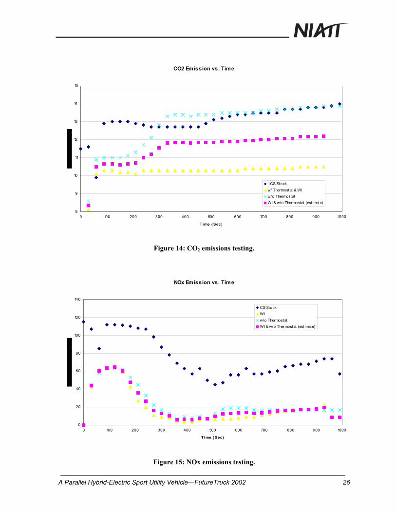
Figure 14 shows that with the modified system, carbon dioxide CO2 emissions are lower then
the stock system. The total reduction in CO2 emissions is approximately 16 percent with
water injection and no thermostat.
Figure 15 shows that with the modified system, NOx emissions are lower then stock. The
modified system reduces overall NOx emissions by approximately 72 percent over a cold
start period.
A Parallel Hybrid-Electric Sport Utility Vehicle—FutureTruck 2002 25
CO2 Emission vs. Time
8
9
10
11
12
13
14
15
0 100 200 300 400 500 600 700 800 900 1000
T ime ( Sec)
1 CS Stockw/ Thermostat & WIw/o ThermostatWI & w/o Thermostat (est imate)
Figure 14: CO2 emissions testing.
NOx Emission vs. Time
0
20
40
60
80
100
120
140
0 100 200 300 400 500 600 700 800 900 1000
T ime ( Sec)
CS StockWIw/o ThermostatWI & w/o Thermostat (est imate)
Figure 15: NOx emissions testing.
A Parallel Hybrid-Electric Sport Utility Vehicle—FutureTruck 2002 26

Fuel Economy
Fuel economy testing was conducted over a three-mile city loop around the University of
Idaho campus. The loop consisted of changes in elevation, flat portions, and stop-and-go
driving to accurately simulate real-world driving. Since air consumption is a direct
correlation to fuel consumed, the vehicle stock mass-flow rate sensor was used to measure air
consumption.
0
0.05
0.1
0.15
0.2
0.25
0.3
0.35
0 1 2 3 4 5 6 7 8 9 1Loop
Air
(mile
/lb)
0
Modified ICE & Full HEVModified ICE & HydraulicsModified ICEStock ICE
Figure 16: Fuel economy testing.
This data (Fig. 16) shows full HEV mode improved fuel economy 41 percent compared to
the stock vehicle and 19 percent over the modified ICE
Competition Results
At the June 2003 FutureTruck competition at Ford’s Michigan Proving Ground, the Summit
placed 11th out of 15 vehicles. Successes included a telematics award and fully functional
electric and hydraulic systems during all competition events. During the 105-mile fuel
economy and acceleration events, the systems performed without incident. However, lack of
A Parallel Hybrid-Electric Sport Utility Vehicle—FutureTruck 2002 27
refinement in the hydraulics system and problems with the vehicle’s internal combustion
engine were setbacks.
The primary problem with the hydraulics centered on the design concept of providing
regenerative braking, power assist, and extended four wheel drive with the same system.
With a myriad of hoses and valves, the system was complex with many opportunities for
failure. During competition, the energy captured during regenerative braking and stored in
the high pressure accumulator tank would drain back to other parts of the system before the
energy could be utilized for power assist. In addition, the engine–driven pump would
periodically operate to readjust pressures as specified by the control system. These
inefficiencies had a negative effect on fuel economy.
Problems with the internal combustion engine included failure of the accelerator cable, dirt in
the fuel system, and failure of the engine management system to operate in closed loop
mode. The breakdowns resulted in a loss of points, and having to operate in a back-up, open
loop mode increased the tailpipe emissions.
The telematics system received a second place award for best design. Cisco Systems, a
headline sponsor, presented this award.
A Parallel Hybrid-Electric Sport Utility Vehicle—FutureTruck 2002 28

CONCLUSION
The University of Idaho Advanced Vehicles Concepts Team successfully modified a 2002
Ford Explorer SUV into a unique, mild-hybrid vehicle to improve fuel economy and reduce
emissions. With both electrics and hydraulics providing regenerative braking and power
assist on a city-driving loop, fuel economy increased by 41 percent compared to the stock
vehicle. By utilizing computerized cooling control, water injection, and vacuum packed
catalytic converters during engine cold start, hydrocarbons decreased by 44 percent
compared to the stock engine.
The telematics system, which included specialized controls and displays for hybrid operation
and vehicle entertainment, earned a second place award at competition for the best design.
The backbone of this project was the multi-disciplinary team, which represented a large
cross-section of the UI student population. By implementing a professional, business
approach for this project, the team safely modified and tested a modern SUV while gaining
valuable knowledge and experience. By conducting a series of public relations events and
partnering with industry and government, the student team successfully transferred their
enthusiasm and knowledge about clean vehicle technologies to a broad spectrum of people.
A Parallel Hybrid-Electric Sport Utility Vehicle—FutureTruck 2002 29

A Parallel Hybrid-Electric Sport Utility Vehicle—FutureTruck 2002 30
REFERENCES
1. www.futuretruck.org. 4/01/03.
2. www.transportation.anl.gov/ttrdc/assessments/ct21-EPRI.html, 9/15/02.
3. Lechner, T. M., “Comparing the Impacts and Benefits of Hybrid Vehicle Options,”
Proceedings of Seventeenth Intl. Electric Vehicle Symposium and Expo, 2000.
4. Cuddy, M.R., Wipke, K.B., “Analysis of the Fuel Economy Benefit of Drivetrain
Hybridization.” SAE Technical Paper 970289, 1997.
5. Tamor, M.A., “Hybrid Vehicle Modeling,” presented at ENV ’96, February 1996.
6. Mason W.T., Kristiansson, U., “Hybrid EVs versus Pure EVs: Which Gives Greater
Benefits?” SAE Paper No. 94C017.
7. Wipke, K., Cuddy, M., “Using an Advanced Vehicle Simulator (ADVISOR) to Guide
Hybrid Vehicle Propulsion System Development,” Presented at the NESEA 1996
Sustainable Transportation Conference, New York, NY, September 16, 1996.
8. National Renewable Energy Laboratory, “ADVISOR,”
http://www.ctts.nrel.gov/analysis/advisor.html, 4/10/02.
9. “Flexible Fueled Vehicle Fleet Manager Guide,” Minnesota Center for Automotive
Research, 1999.
10. Georgi, P. “42 Volts, Smart or Sexy?” Batteries Digest Newsletter, April 2001, p3.
11. “48 Hours in Hell.” Motor Trend. September 2001. p. 44.
12. National Ethanol Vehicle Coalition;
http://www.e85fuel.com/information/consumers.htm
13. White, R. A. and Korst, H. H., “The Determination of Vehicle Drag Contribution
from Coast-Down Test,” SAE Paper 720099, 1972.