Embed Size (px)
Citation preview
Internationl Journal of Rotating Machinery1995, Vol. 2, No. 2, pp. 123-129Reprints available directly from the publisherPhotocopying permitted by license only
(C) 1995 OPA (Overseas Publishers Association)Amsterdam B.V. Published in The Netherlands
by Harwood Academic Publishers GmbHPrinted in Singapore
A Numerical Analysis on Flow and Heat Transfer inthe Entrance Region of an Axially Rotating Pipe
SHUICHI TORIIDepartment of Mechanical Engineering, Kagoshima University, 1-21-40 Korimoto, Kagoshima 890, Japan
WEN-JEI YANGDepartment of Mechanical Engineering and Applied Mechanics, The University of Michigan, Ann Arbor, Michigan, 48109,
U.S.A.
A numerical study is performed to investigate turbulent flow and heat transfer characteristics in the entrance region of a piperotating around its axis. Various different k-e turbulence models are employed whose function consists of the Richardsonnumber in the e model to take swirling into account. The axial rotation of the pipe suppresses thermal development andcauses a substantial decrease in the Nusselt number along the flow. It is disclosed from the study that an increase in therotation rate induces a reduction in the velocity gradient, turbulent kinetic energy and Reynolds stress in the vicinity of thewall and a substantial deformation of these radial profiles in the downstream direction. It results in both a suppression ofthe thermal development and an attenuation in the Nusselt number along the flow.
Key Words: Numerical analysis; swirling flow; turbulent flow; pipe flow; heat transfer
INTRODUCTION
Transport phenomena in a pipe rotating around its axisare encountered in many industrial applications such asflows in the inlet part of fluid machinery, rotating heatexchangers and cooling systems of rotors. There wasmany numerical and experimental investigations on thissubject, but only a few will be cited below, which arepertinent to the present study.Murakami and Kikuyama [1980] conducted an experi-
mental study on the velocity profile and hydraulic loss ina saturated downstream region of a rotating pipe. It wasdisclosed that both turbulence and hydraulic loss wereremarkably reduced due to pipe rotation and that stream-wise velocity profile gradually deformed into a parabolicform with an increase in its speed. Kikuyama et al.[1983] determined the variation of streamwise velocityprofiles using a modified mixing length theory proposedby Bradshaw [1969]. The same numerical analysis wasperformed by Hirai et al. [1986] using the Reynoldsstress model. It was found that a change in flow charac-teristics induced by a swirl could be attributed to adecrease in the Reynolds stress. A combined experimen-
tal and theoretical study was performed to determine theeffects of pipe rotation on fluid flow and heat transfer ina thermally and hydrodynamically fully developed flowregion [1988]. It was found that an increase in therotation rate resulted in a decrease in heat transferperformance with the Nusselt number asymptoticallyapproaching that of a laminar pipe flow. Torii and Yang[1994] modified the existing k-e turbulence models toincrease swirling effects. In their model, a functionincluding the Richardson numbers was proposed andintroduced into the e equation. The model yields sub-stantial decreases in the friction coefficient, turbulentkinetic energy, Reynolds stress and streamwise velocitygradient in the vicinity of the wall.
Nishibori et al. [1987] investigated the transport phe-nomena in the entrance region of an axially rotating pipe.The boundary layer was found to be strongly stabilizedby the centrifugal force due to the rotating velocitycomponent, resulting in a laminarization of the flow.Weigrand and Beer [1990] investigated fluid flow andheat transfer characteristics in a combined hydrodynamicand thermal entrance region using a modified mixinglength hypothesis, which takes into account turbulence
124 S. TORII AND W-J. YANG
suppression due to the centrifugal force. It was disclosedthat the entrance length increases significantly with anincrease in the rotation rate. However, flow laminariza-tion mechanisms in the entrance region, particularlychanges in the flow structures due to pipe rotation, arenot clearly understood.The purpose of the present study is to investigate
transport phenomena in a hydorodynamically-and-ther-mally-developing flow region of an axially rotating pipewith uniform heat flux. Emphasis is placed on the effectsof pipe rotation on flow structures and heat transfer rate.Numerical results obtained by using the existing k-eturbulence models are compared.
THEORETICAL ANALYSIS
r direction:
0 direction:
W2 10P
r 90r
Ow Ow vwu+vOx Or r
Energy equation:
(3)
W(-)
10 r r
20---r ( r3v r2Or v’w’} (4)
OT OT 0 OTu- + v--= (ra rv’t’) (5)Ox Or rOr Or
Governing Equations
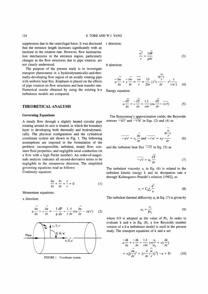
A steady flow through a slightly heated circular piperotating around its axis is treated, in which the boundarylayer is developing both thermally and hydrodynami-cally. The physical configuration and the cylindricalcoordinate system are shown in Fig. 1. The followingassumptions are imposed in the formulation of theproblem: incompressible, turbulent, steady flow: con-stant fluid properties; and negligible axial conduction (ina flow with a high Peclet number). An order-of-magni-tude analysis indicates all second-derivative terms to benegligible in the streamwise direction. The simplifiedgoverning equations read as follows:Continuity equation:
OU
Ox
Momentum equations"
x direction:
+ + 0 (1)Or r
The Boussinesq’s approximation yields, the Reynoldsstresses -u’v’ and -v’w’ in Eqs. (2) and (4) as
-u’v’ v and -v’w’ l)trOr Or
and the turbulent heat flux -v’t’ in Eq. (5) as
(6)
-v’t’ ol.Or
(7)
The turbulent viscosity 1) in Eq. (6) is related to theturbulent kinetic energy k and its dissipation ratethrough Kolmogorov-Prandtl’s relation [1982], as
k2v, Cf.- (8)
The turbulent thermal diffusivity o in Eq. (7) is given by
Ou OuU+V’-Ox Or
ldP 0 Ou- (rv-- ru’v’) (2)p dx r Or Or
FIGURE Coordinate system.
"1)
(9)O/’t Pr---where 0.9 is adopted as the value of Prt. In order toevaluate k and e in Eq. (8), a low Reynolds numberversion of a k-e turbulence model is used in the presentstudy. The transport equations of k and e are
Ok Ok 0 Oku--+ v-- {r(Vt + v) _--}Ox Or rOr % Or-
Ou 0 wq- 1,’,[(-ff-)2 q- { r 7- (--) } 21 --e + D
or or r(10)
ENTRANCE REGION OF ROTATING PIPE 125
Oe Oe 0 v. Oeu--+ v--- {r(---:’ + v) }Ox Or rOr % -r. OU 2 0 14)
2]!2
--Clf 1),[(7 "nt- {rr (7)} -C2Ca/2 + E (11)
The k-e models proposed by Launder and Sharma[1974], Nagano and Hishida [1987], and Torii et al.[1990] are employed in the present study. In order toinclude swirling effect, the model function, C3 (in Eq.11)), proposed by Torii and Yang [1994]
C -0.06Ri’5, (12)
is employed where
k2wO(rw)Ri (13)eZrZOr
The empirical constants and model functions in Eqs. (8),(10) and (11) are summarized in Table for the threeturbulence models.As pointed out by Kawamura and Mishima [1991] and
Torii and Yang [1994], if m the approximation of -v’w’in Eq. (6), is employed, the radial profile of the tangentialvelocity would become linear, and consequently turbu-lence suppression due to the centrifugal force of aswirling flow would not take place. Weigand and Beer[1990] measured the radial profiles of the time-averagedtangential velocity at different axial locations and derived
the universal tangential profiles as
where
rw W(-) (2 + f(z*)) (14)
f(z*) -2 + 9.5e-’19z* (15)z
In the present study, Eq. (14) is employed to replace Eq.(14) in determining the tangential velocity equation.A hydrodynamically, fully-developed isothermal tur-
bulent flow in the absence of rotation is assumed as theinlet condition. Only one-half of the pipe cross section istreated because of a symmetry in the fluid flow. Thus, theboundary conditions are specified asr 0 (center line):
Ou Ow Ok Oe OT
Or Or Or Or Or
r d/2 (wall)"
u v k e 0, w W(tangentialvelocity),0T q__.w (constantheatflux)Or k
The ranges of the parameters in the present study are:Reynolds numbers Re 5,000 and 10,000, Prandtl
Launder &Sharma
TABLEEmpirical constants and model functions
Nagano &Hishida
Torii et al.
CaCC2C3o-
o-
fl
f2
f.
D
E
0.09
1.452.0
1.01.01.31.0
0.3exp(- R)
exp(1 R/50)
2vvt \ Or
0.091.451.9
1.01.0
1.31.0
0.3exp(- R)
{1 exp(.5)}2V(rk)
vv,(1 f,) \ Or
0.091.441.91.01.0
1.3
Rt+ O. 15exp( -)0.3exp(- R)
(1- exP(2-5.5)}-2v(O’)Or
vv,(1 f,,) \ Or
126 S. TORII AND W-J. YANG
number Pr 0.7 (air) and rotation rates N 0, 1, 2 and3.
Numerical Method
The governing equations employed are discretized usinga control volume finite difference procedure [1980].Since all turbulence quantities as well as the time-averaged axial and tangential velocities vary rapidly inthe near-wall region, two control volumes are alwayslocated within the viscous sublayer, y+. 5. The radialmesh size is increased from a minimum value adjacent tothe wall towards the center line in geometrical propor-tion, and the maximum control volume size near thecenter line is always kept within 3% of d/2. Meanwhile,the axial control volume size is constant at five times theminimum radial size for the wall. Since the governingequations are essentially parabolic, calculation is per-formed from the inlet in the downstream direction bymeans of the marching procedure. At each axial location,the axial pressure gradient dP/dx is assumed and theprocedure is repeated until the criterion of convergence issatisfied, which is set at
max(M (M-M-1
max
<10-4 (16)
for all the variables + (u, v, T, k, and e). The superscriptsM and M in Eq. (16) indicate two successiveiterations, while the subscript "max" refers to a maxi-mum value over the entire fields of iterations. Since thestreamwise velocity obtained must satisfy the continueequation, the axial pressure gradient is corrected and thecomputation is repeated for a new axial velocity, until thetotal mass flow rate is satisfied under the criterion:
ff-SMo, r- f -< 10-5 (17)
ff-i,,dOdrwhere Ucp is the axis velocity under the correctionprocess.
Throughout numerical calculations, the number ofcontrol volumes in the radial direction was properlyselected between 51 and 78 to ensure validation of thenumerical procedures as well as to obtain grid-indepen-dent solutions. The maximum relative error over alldependent variables within this change of grid spacingwas kept within 1%. The computations are processed inthe following order:
1. Specify the initial values of u, v, w, T, k, and e, andassign a constant axial pressure gradient.
2. Solve the equations of u, v, T, k, e, and Eq. (14) forW.
3. Repeat step 2 until the criterion of convergence, Eq.(16), is satisfied for all dependent variables.
4. Calculate new values of u, v, w, T, k, and e with acorrected new axial pressure gradient.
5. Repeat steps 2-4 until the conservation of thestreamwise flow rate is satisfied under the criterion,i.e. Eq. (17), followed by evaluating convergentvalues of u, v, w, T, k, and e.
6. Repeat step 2-5 until x reaches the designated length.
The CPU time required in computing this scheme wasabout 24 to 100 hours on a NEC personal computer (32bit), depending on the number of control volumes used.
RESULTS AND DISCUSSION
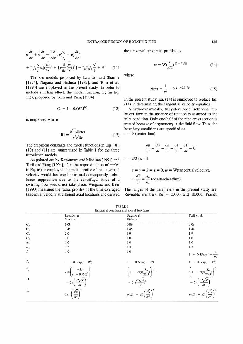
Numerical results for the Nusselt number Nu are illus-trated in Figs. 2, 3 and 4 in the form of Nu/Nu versusx/d, with N as the parameter, for the k- models ofLaunder and Sharma [1974], Nagano and Hishida[1987], and Torii et al. [1990], respectively. Here, Nuodenotes Nu for a fully-developed turbulent pipe flowwithout rotation. The cases (a) and (b) in each figurecorrespond to Re 5,000 and 10,000 respectively. TheNusselt number decreases monotonically along the flowdue to the thermal entrance effect, and approaches anasymptotic value. It is observed that for a given Re, an
4
0 50 100/d
ta) R5,000
4 N=O
_2
00 50 O0
x,/dtb) Re= I0.000
FIGURE 2 Local Nusselt number using the k model of Launderand Sharma [1974], at (a) Re 5,000 and (b) 10,000.
ENTRANCE REGION OF ROTATING PIPE 127
4 N-0
00 50 O0
x/d(a) R5,000
Z
0 50 100x/d
(b Re= 10.000
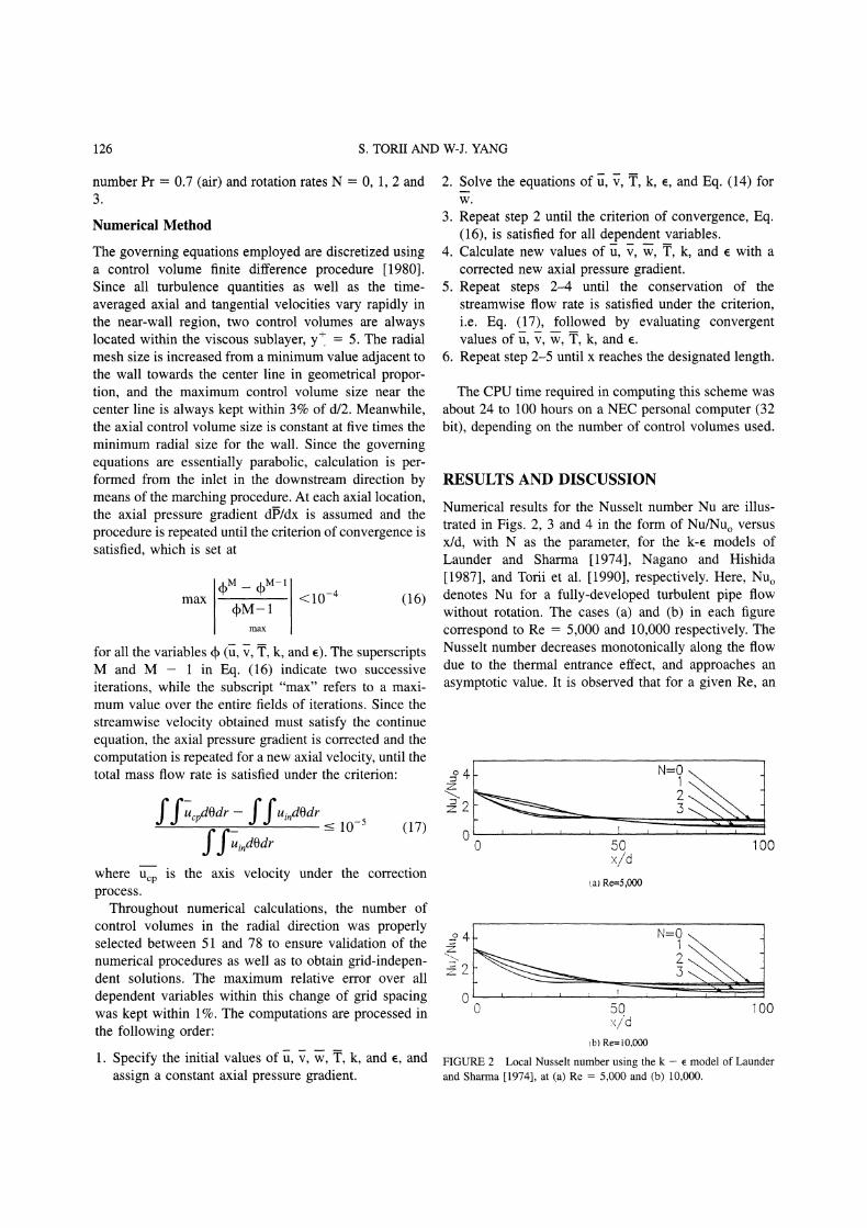
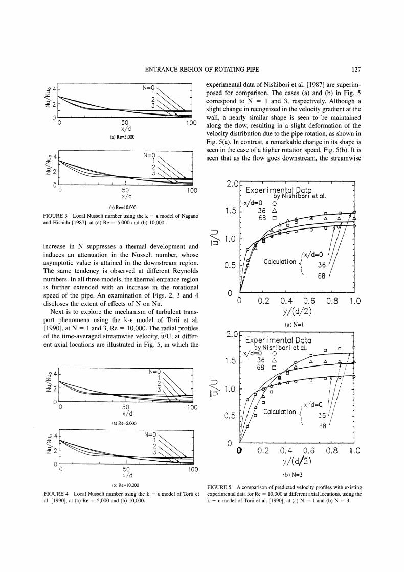
FIGURE 3 Local Nusselt number using the k e model of Naganoand Hishida [1987], at (a) Re 5,000 and (b) 10,000.
increase in N suppresses a thermal development andinduces an attenuation in the Nusselt number, whoseasymptotic value is attained in the downstream region.The same tendency is observed at different Reynoldsnumbers. In all three models, the thermal entrance regionis further extended with an increase in the rotationalspeed of the pipe. An examination of Figs. 2, 3 and 4discloses the extent of effects of N on Nu.
Next is. to explore the mechanism of turbulent trans-port phenomena using the k-e model of Torii et al.[1990], at N and 3, Re 10,000. The radial profilesof the time-averaged streamwise velocity, u/U, at differ-ent axial locations are illustrated in Fig. 5, in which the
4
0 50 100x/d
(a) Re=5.000
00 50 100
x/dtb) Re= 10.000
FIGURE 4 Local Nusselt number using the k e model of Torii etal. [1990], at (a) Re 5,000 and (b) 10,000.
experimental data of Nishibori et al. 1987] are superim-posed for comparison. The cases (a) and (b) in Fig. 5correspond to N and 3, respectively. Although aslight change in recognized in the velocity gradient at thewall, a nearly similar shape is seen to be maintainedalong the flow, resulting in a slight deformation of thevelocity distribution due to the pipe rotation, as shown inFig. 5(a). In contrast, a remarkable change in its shape isseen in the case of a higher rotation speed, Fig. 5(b). It isseen that as the flow goes downstream, the streamwise
Experimental Databy Nishibori et al. "1
x/ =o o :!1.5 6 A
10
o 0.2 o.6 0.8
(a)
2.0) [xerimentol Dcteb Nishibori et ei.
0.5
00 0.2 0.4 0.6 0.8 .0
,bl N=3
FIGURE 5 A comparison of predicted velocity profiles with existingexperimental data for Re 10,000 at different axial locations, using thek e model of Torii et al. [1990], at (a) N and (b) N 3.
128 S. TORII AND W-J. YANG
8.0
6.0
.4.0
2.0
N=IF
0 0.2 0.4 0.6 0.8 1.0
x/d=80
x/d=O
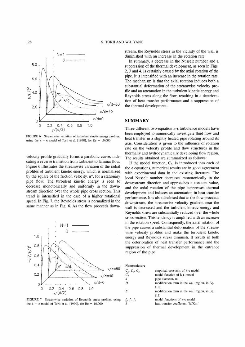
y/(d/2)FIGURE 6 Streamwise variation of turbulent kinetic energy profiles,using the k e model of Torii et al. [1990], for Re 10,000.
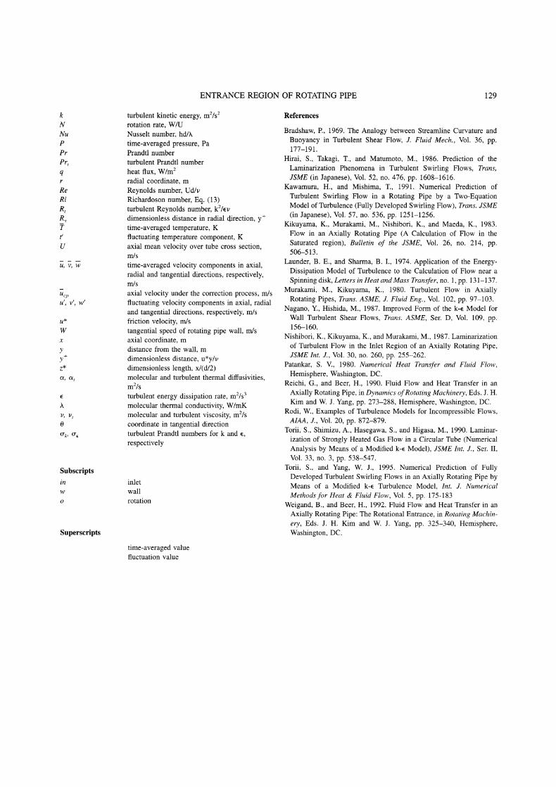
velocity profile gradually forms a parabolic curve, indi-cating a reverse transition from turbulent to laminar flow.Figure 6 illustrates the streamwise variation of the radialprofiles of turbulent kinetic energy, which is normalizedby the square of the friction velocity, u*, for a stationarypipe flow. The turbulent kinetic energy is seen todecrease monotonically and uniformly in the down-stream direction over the whole pipe cross section. Thistrend is intensified in the case of a higher rotationalspeed. In Fig. 7, the Reynolds stress is normalized in thesame manner as in Fig. 6. As the flow proceeds down-
1.0..... 0"8
i/"-"i-> 0.6
0.4
0 0.2
N=I3
x/d=80i’-’"’,"’, x/d-40
x/d=O0.4 0.6 0.8 !.0
y/(d/2)
FIGURE 7 Streamwise variation of Reynolds stress profiles, usingthe k e model of Torii et al. [1990], for Re 10,000.
stream, the Reynolds stress in the vicinity of the wall isdiminished with an increase in the rotation rate.
In summary, a decrease in the Nusselt number and asuppression of the thermal development, as seen in Figs.2, 3 and 4, is certainly caused by the axial rotation of thepipe. It is intensified with an increase in the rotation rate.The mechanism is that the axial rotation induces both asubstantial deformation of the streamwise velocity pro-file and an attenuation in the turbulent kinetic energy andReynolds stress along the flow, resulting in a deteriora-tion of heat transfer performance and a suppression ofthe thermal development.
SUMMARY
Three different two-equation k- turbulence models havebeen employed to numerically investigate fluid flow andheat transfer in a slightly heated pipe rotating around itsaxis. Consideration is given to the influence of rotationrate on the velocity profile and flow structures in thethermally and hydrodynamically developing flow region.The results obtained are summarized as follows:
If the model function, C3, is introduced into each ofthe equations, numerical results are in good agreementwith experimental data in the existing literature. Thelocal Nusselt number decreases monotonically in thedownstream direction and approaches a constant value,and the axial rotation of the pipe suppresses thermaldevelopment and induces an attenuation in heat transferperformance. It is also disclosed that as the flow proceedsdownstream, the streamwise velocity gradient near thewall is decreased and the turbulent kinetic energy andReynolds stress are substantially reduced over the wholecross section. This tendency is amplified with an increasein the rotation speed. Consequently, the axial rotation ofthe pipe causes a substantial deformation of the stream-wise velocity profiles and make the turbulent kineticenergy and Reynolds stress diminish. It results in boththe deterioration of heat transfer performance and thesuppression of thermal development in the entrance
region of the pipe.
Nomenclature
CA, C1, C empirical constants of k-e model
C model function of k-e modeld pipe diameter, mD modification term in the wall region, in Eq.
(10)E modification term in the wall region, in Eq.
(11)f,, fl, f2 model functions of k-e modelh heat transfer coefficient, W/Km
ENTRANCE REGION OF ROTATING PIPE 129
kNNuPPrPrtq
ReRi
RtR,Tt’U
U, V, W
UcpU V W
U*
yy+Z*og, o
V, V
0
O’k, O"
Subscripts
inwo
Superscripts
turbulent kinetic energy, m2/srotation rate, W/UNusselt number, hd/.
time-averaged pressure, PaPrandtl numberturbulent Prandtl numberheat flux, W/mradial coordinate, mReynolds number, Ud/v
Richardoson number, Eq. (13)turbulent Reynolds number, kZ/!vdimensionless distance in radial direction, y+time-averaged temperature, Kfluctuating temperature component, Kaxial mean velocity over tube cross section,m/s
time-averaged velocity components in axial,radial and tangential directions, respectively,m/s
axial velocity under the correction process, m/s
fluctuating velocity components in axial, radialand tangential directions, respectively, m/s
friction velocity, m/s
tangential speed of rotating pipe wall, m/s
axial coordinate, mdistance from the wall, mdimensionless distance, u*y/vdimensionless length, x/(d/2)molecular and turbulent thermal diffusivities,mZ/sturbulent energy dissipation rate, m2/smolecular thermal conductivity, W/mKmolecular and turbulent viscosity, m2/scoordinate in tangential directionturbulent Prandtl numbers for k and e,respectively
inletwallrotation
time-averaged valuefluctuation value
References
Bradshaw, P., 1969. The Analogy between Streamline Curvature andBuoyancy in Turbulent Shear Flow, J. Fluid Mech., Vol. 36, pp.177-191.
Hirai, S., Takagi, T., and Matumoto, M., 986. Prediction of theLaminarization Phenomena in Turbulent Swirling Flows, Trans,JSME (in Japanese), Vol. 52, no. 476, pp. 1608-1616.
Kawamura, H., and Mishima, T., 1991. Numerical Prediction ofTurbulent Swirling Flow in a Rotating Pipe by a Two-EquationModel of Turbulence (Fully Developed Swirling Flow), Trans. JSME(in Japanese), Vol. 57, no. 536, pp. 1251-1256.
Kikuyama, K., Murakami, M., Nishibori, K., and Maeda, K., 1983.Flow in an Axially Rotating Pipe (A Calculation of Flow in theSaturated region), Bulletin of the JSME, Vol. 26, no. 214, pp.506-513.
Launder, B. E., and Sharma, B. I., 1974. Application of the Energy-Dissipation Model of Turbulence to the Calculation of Flow near aSpinning disk, Letters in Heat and Mass Transfer, no. 1, pp. 131-137.
Murakami, M., Kikuyama, K., 1980. Turbulent Flow in AxiallyRotating Pipes, Trans. ASME, J. Fluid Eng., Vol. 102, pp. 97-103.
Nagano, Y., Hishida, M., 1987. Improved Form of the k-e Model forWall Turbulent Shear Flows, Trans. ASME, Set. D, Vol. 109, pp.156-160.
Nishibori, K., Kikuyama, K., and Murakami, M., 1987. Laminarizationof Turbulent Flow in the Inlet Region of an Axially Rotating Pipe,JSME Int. J., Vol. 30, no. 260, pp. 255--262.
Patankar, S. V., 1980. Numerical Heat Transfer and Fluid Flow,Hemisphere, Washington, DC.
Reichi, G., and Beer, H., 1990. Fluid Flow and Heat Transfer in anAxially Rotating Pipe, in Dynamics ofRotating Machinery, Eds. J. H.Kim and W. J. Yang, pp. 273-288, Hemisphere, Washington, DC.
Rodi, W., Examples of Turbulence Models for Incompressible Flows,AIAA, J., Vol. 20, pp. 872-879.
Torii, S., Shimizu, A., Hasegawa, S., and Higasa, M., 1990. Laminar-ization of Strongly Heated Gas Flow in a Circular Tube (NumericalAnalysis by Means of a Modified k-e Model), JSME Int. J., Ser. II,Vol. 33, no. 3, pp. 538-547.
Torii, S., and Yang, W. J., 1995. Numerical Prediction of FullyDeveloped Turbulent Swirling Flows in an Axially Rotating Pipe byMeans of a Modified k-e Turbulence Model, Int. J. NumericalMethods for Heat & Fluid Flow, Vol. 5, pp. 175-183
Weigand, B., and Beer, H., 1992. Fluid Flow and Heat Transfer in an
Axially Rotating Pipe: The Rotational Entrance, in Rotating Machin-ery, Eds. J. H. Kim and W. J. Yang, pp. 325-340, Hemisphere,Washington, DC.

International Journal of
AerospaceEngineeringHindawi Publishing Corporationhttp://www.hindawi.com Volume 2010
RoboticsJournal of
Hindawi Publishing Corporationhttp://www.hindawi.com Volume 2014
Hindawi Publishing Corporationhttp://www.hindawi.com Volume 2014
Active and Passive Electronic Components
Control Scienceand Engineering
Journal of
Hindawi Publishing Corporationhttp://www.hindawi.com Volume 2014
International Journal of
RotatingMachinery
Hindawi Publishing Corporationhttp://www.hindawi.com Volume 2014
Hindawi Publishing Corporation http://www.hindawi.com
Journal ofEngineeringVolume 2014
Submit your manuscripts athttp://www.hindawi.com
VLSI Design
Hindawi Publishing Corporationhttp://www.hindawi.com Volume 2014
Hindawi Publishing Corporationhttp://www.hindawi.com Volume 2014
Shock and Vibration
Hindawi Publishing Corporationhttp://www.hindawi.com Volume 2014
Civil EngineeringAdvances in
Acoustics and VibrationAdvances in
Hindawi Publishing Corporationhttp://www.hindawi.com Volume 2014
Hindawi Publishing Corporationhttp://www.hindawi.com Volume 2014
Electrical and Computer Engineering
Journal of
Advances inOptoElectronics
Hindawi Publishing Corporation http://www.hindawi.com
Volume 2014
The Scientific World JournalHindawi Publishing Corporation http://www.hindawi.com Volume 2014
SensorsJournal of
Hindawi Publishing Corporationhttp://www.hindawi.com Volume 2014
Modelling & Simulation in EngineeringHindawi Publishing Corporation http://www.hindawi.com Volume 2014
Hindawi Publishing Corporationhttp://www.hindawi.com Volume 2014
Chemical EngineeringInternational Journal of Antennas and
Propagation
International Journal of
Hindawi Publishing Corporationhttp://www.hindawi.com Volume 2014
Hindawi Publishing Corporationhttp://www.hindawi.com Volume 2014
Navigation and Observation
International Journal of
Hindawi Publishing Corporationhttp://www.hindawi.com Volume 2014
DistributedSensor Networks
International Journal of