Embed Size (px)
Citation preview
1
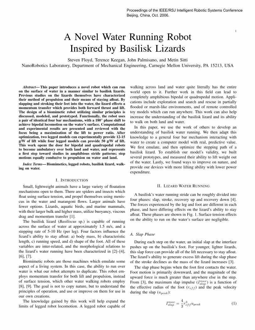
A Novel Water Running RobotInspired by Basilisk Lizards
Steven Floyd, Terence Keegan, John Palmisano, and Metin SittiNanoRobotics Laboratory, Department of Mechanical Engineering, Carnegie Mellon University, PA 15213, USA
Abstract— This paper introduces a novel robot which can runon the surface of water in a manner similar to basilisk lizards.Previous studies on the lizards themselves have characterizedtheir method of propulsion and their means of staying afloat. Byslapping and stroking their feet into the water, the lizard effects amomentum transfer which provides both forward thrust and lift.The design of a biomimetic robot utilizing similar principles isdiscussed, modeled, and prototyped. Functionally, the robot usesa pair of identical four bar mechanisms, with a 180o phase shift toachieve bipedal locomotion on the water’s surface. Computationaland experimental results are presented and reviewed with thefocus being a maximization of the lift to power ratio. Afteroptimization, two legged models can experimentally provide 12-15g/W of lift while four legged models can provide 50 g/W of lift.This work opens the door for bipedal and quadrupedal robotsto become ambulatory over both land and water, and representsa first step toward studies in amphibious stride patterns; stepmotions equally conducive to propulsion on water and land.
Index Terms— Biomimetics, legged robots, basilisk lizard, walk-ing on water.
I. INTRODUCTION
Small, lightweight animals have a large variety of floatationmechanisms open to them. There are spiders and insects whichfloat using surface tension, and propel themselves using menis-cus in the water and marangoni flows. Larger animals havefewer options. Lizards, aquatic birds, and marine mammals,with their larger bulk and higher mass, utilize buoyancy, viscousdrag and momentum transfer [1].
The basilisk lizard (Basiliscus sp.) is capable of runningacross the surface of water at approximately 1.5 m/s, and astepping rate of 5-10 Hz (per leg). Four factors influence thelizard’s ability to stay afloat: a) body mass, b) characteristiclength, c) running speed, and d) shape of the foot. All of thesevariables are inter-related, and the morphological relations tothe lizard’s water running have been characterized in [2]–[4],[6], [7].
Biomimetic robots are those machines which emulate someaspect of a living system. In this case, the ability to run overwater is what our robot attempts to duplicate. This robot em-ploys momentum transfer for both lift and propulsion, insteadof surface tension, which other water walking robots employ[8], [9]. The goal is not to copy nature, but to understand theprinciples of operation, and use or improve on them for use inour own creations.
The knowledge gained by this work will help expand thelimits of legged robot locomotion. A legged robot capable of
walking across land and water quite literally has the entireworld open to it. Further work in this field can lead tocompletely amphibious bipedal or quadrupedal motion. Appli-cations include exploration and search and rescue in partiallyflooded or marsh-like environments, and of remote controlledtoy models which can run anywhere. This work can also helpincrease the understanding of the basilisk lizard and its abilityto walk on both land and water.
In this paper, we use the work of others to develop anunderstanding of basilisk water running. We then adapt thisknowledge to a general four bar mechanism interacting withwater to create a computer model with real, predictive value.We first emulate, and then optimize the stepping path of abasilisk lizard. To establish our model’s validity, we builtseveral prototypes, and measured their ability to lift weight outof the water. Lastly, we found ways to improve on nature, andprovide our devices with more lifting ability with lower powerexpenditure.
II. LIZARD WATER RUNNING
A basilisk’s water running stride can be roughly divided intofour phases: slap, stroke, recovery up and recovery down [4].The forces experienced by the leg and foot are different in eachphase, and have differing effects on the lizard’s ability to stayafloat. These phases are shown in Fig. 1. Surface tension effectson the ability to run on the water’s surface are negligible.
A. Slap Phase
During each step on the water, an initial slap at the interfacepushes up on the basilisk’s foot. For younger, lighter lizards,this slap force can provide all of the lift necessary to stay afloat.The lizard’s ability to generate excess lift during the slap phaseof the stroke declines as the mass of the lizard increases [3].
The slap phase begins when the foot first contacts the water.Foot motion is primarily downward, and the magnitude of theupward force is much greater than anywhere else in the step.From [3], the maximum slap impulse (Imax
slap ) is a function ofthe effective radius of the foot (reff ) and the peak velocityduring the slap (upeak):
Imaxslap =
43r3effupeak (1)

Fig. 1. Phases of a basilisk lizard’s step. Time for each frame is shown in milliseconds in the upper right corner. Reprinted with permission from [4].
B. Stroke PhaseAfter the slap phase, the lizard pushes against the water
beneath its foot, stroking downward and creating an air cavityin the water. The momentum transfer from the lizard’s footto the water during this stroke phase generates the rest of thelift force necessary to stay afloat most of the forward thrust.While basilisk lizards do apply significant forces to the waterin a lateral fashion, it is felt this is done for balance andstabilization, and not for lift. Or, this lateral motion may bean anatomical limitation imposed by the creature’s posture [6].It is important for the lizard to retract its foot from the aircavity before it collapses, or it will sink.
For heavier lizards, most of the lift comes from the strokephase. The drag on the foot is a combination of hydrostaticdrag due to increasing depth, and inertial drag from momentumtransferred to the fluid. From [2], [3], a good fit for a lizard’sfoot - or a disk - entering the water is:
D(t) = C∗D[0.5Sρu2 + Sρgh(t)] (2)
where D(t) is the time varying drag force, C∗D ≈ 0.703 is
the constant drag coefficient, ρ is the density of water, g isacceleration due to gravity, S = πr2
eff is the area over whichdrag is occurring, and h(t) is the time varying depth of the foot.This holds true over a large range of velocities for both lizardsand experimental equipment.
C. Recovery Up and Recovery DownWhen pulling its foot out of the water during the recovery
up phase, the basilisk lizard will curl the toes inward, toprevent accidental drag on the cavity walls. This takes placeentirely within the air cavity, and must be completed beforethe cavity collapses. During recovery down, the speed of thestride increases as the lizard prepares to slap the water surfacein the next stride. No significant forces are experienced by thelizard’s foot in either of these phases.
D. TimingThe period of time that the cavity is open (Tseal) is dependent
upon the shape of the foot of the lizard [3]. For a circular disk,the relationship is as follows:
Tseal = 2.285(reff/g)0.5 (3)
This period sets an absolute minimum on the frequency. Thelizard must slap down, stroke, and remove its foot from thecavity in less than Tseal seconds. This equation demonstratesthat larger feet can, in theory, lead to slower stride frequencies,but there seems to be no correlation in the wild; all basilisksrun at the same pace [3].
III. FOUR BAR MECHANISM MODELING
To mimic the motion of a basilisk’s legs, a four bar mech-anism in a Grashof crank-rocker configuration was used. Be-cause the four bar mechanism is planar, only the side projectionof the lizard’s motion can be emulated. After development, thecomputer model was used to make predictions of the lift a givenfour bar mechanism could provide.
A. KinematicsFig. 2 shows a four bar linkage and its resultant loop
shape. Link A is assumed to be the body, and is consideredstationary in all computer models. Lengths of all four linkagesare variables, and the angle of Link A is also variable. The tipof Link E is considered the ankle of the mechanism.
Using equations and relations found in [5], it is possible toderive the position and angles of Links C and D given the
Fig. 2. Diagram of a generic four bar mechanism with links labeled. Theloop followed by the tip of Link E is shown.
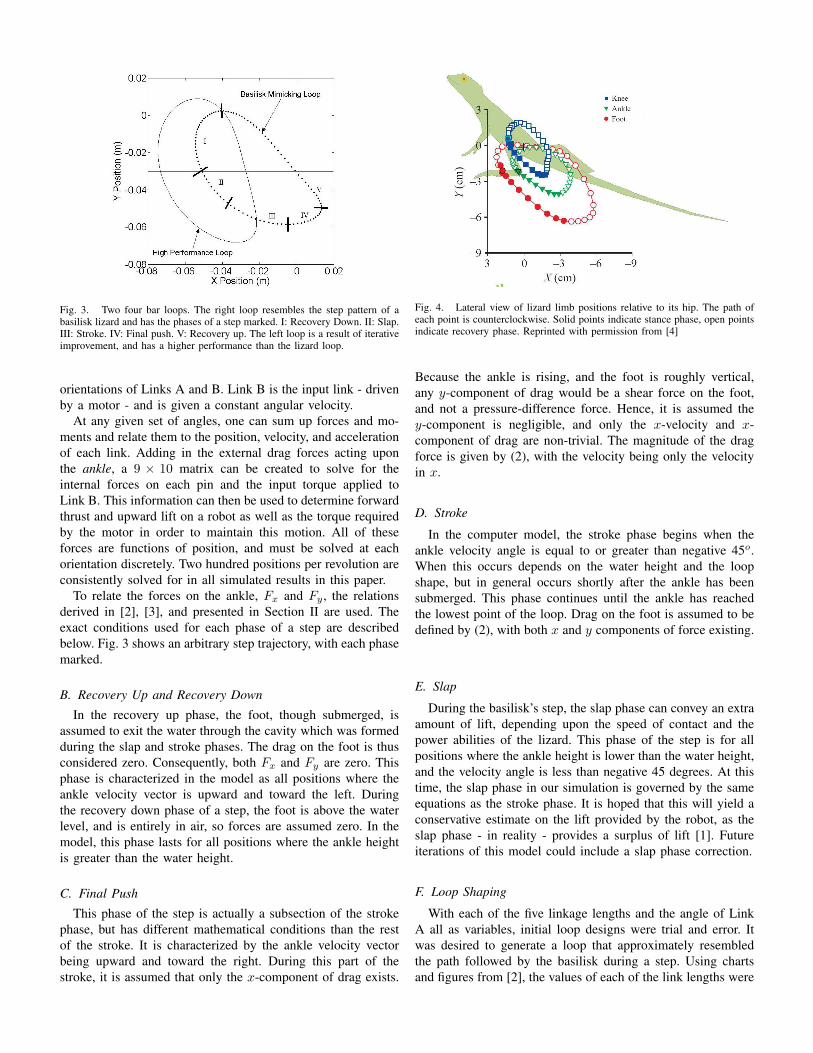
Fig. 3. Two four bar loops. The right loop resembles the step pattern of abasilisk lizard and has the phases of a step marked. I: Recovery Down. II: Slap.III: Stroke. IV: Final push. V: Recovery up. The left loop is a result of iterativeimprovement, and has a higher performance than the lizard loop.
orientations of Links A and B. Link B is the input link - drivenby a motor - and is given a constant angular velocity.
At any given set of angles, one can sum up forces and mo-ments and relate them to the position, velocity, and accelerationof each link. Adding in the external drag forces acting uponthe ankle, a 9 × 10 matrix can be created to solve for theinternal forces on each pin and the input torque applied toLink B. This information can then be used to determine forwardthrust and upward lift on a robot as well as the torque requiredby the motor in order to maintain this motion. All of theseforces are functions of position, and must be solved at eachorientation discretely. Two hundred positions per revolution areconsistently solved for in all simulated results in this paper.
To relate the forces on the ankle, Fx and Fy , the relationsderived in [2], [3], and presented in Section II are used. Theexact conditions used for each phase of a step are describedbelow. Fig. 3 shows an arbitrary step trajectory, with each phasemarked.
B. Recovery Up and Recovery DownIn the recovery up phase, the foot, though submerged, is
assumed to exit the water through the cavity which was formedduring the slap and stroke phases. The drag on the foot is thusconsidered zero. Consequently, both Fx and Fy are zero. Thisphase is characterized in the model as all positions where theankle velocity vector is upward and toward the left. Duringthe recovery down phase of a step, the foot is above the waterlevel, and is entirely in air, so forces are assumed zero. In themodel, this phase lasts for all positions where the ankle heightis greater than the water height.
C. Final PushThis phase of the step is actually a subsection of the stroke
phase, but has different mathematical conditions than the restof the stroke. It is characterized by the ankle velocity vectorbeing upward and toward the right. During this part of thestroke, it is assumed that only the x-component of drag exists.
Fig. 4. Lateral view of lizard limb positions relative to its hip. The path ofeach point is counterclockwise. Solid points indicate stance phase, open pointsindicate recovery phase. Reprinted with permission from [4]
Because the ankle is rising, and the foot is roughly vertical,any y-component of drag would be a shear force on the foot,and not a pressure-difference force. Hence, it is assumed they-component is negligible, and only the x-velocity and x-component of drag are non-trivial. The magnitude of the dragforce is given by (2), with the velocity being only the velocityin x.
D. Stroke
In the computer model, the stroke phase begins when theankle velocity angle is equal to or greater than negative 45o.When this occurs depends on the water height and the loopshape, but in general occurs shortly after the ankle has beensubmerged. This phase continues until the ankle has reachedthe lowest point of the loop. Drag on the foot is assumed to bedefined by (2), with both x and y components of force existing.
E. Slap
During the basilisk’s step, the slap phase can convey an extraamount of lift, depending upon the speed of contact and thepower abilities of the lizard. This phase of the step is for allpositions where the ankle height is lower than the water height,and the velocity angle is less than negative 45 degrees. At thistime, the slap phase in our simulation is governed by the sameequations as the stroke phase. It is hoped that this will yield aconservative estimate on the lift provided by the robot, as theslap phase - in reality - provides a surplus of lift [1]. Futureiterations of this model could include a slap phase correction.
F. Loop Shaping
With each of the five linkage lengths and the angle of LinkA all as variables, initial loop designs were trial and error. Itwas desired to generate a loop that approximately resembledthe path followed by the basilisk during a step. Using chartsand figures from [2], the values of each of the link lengths were
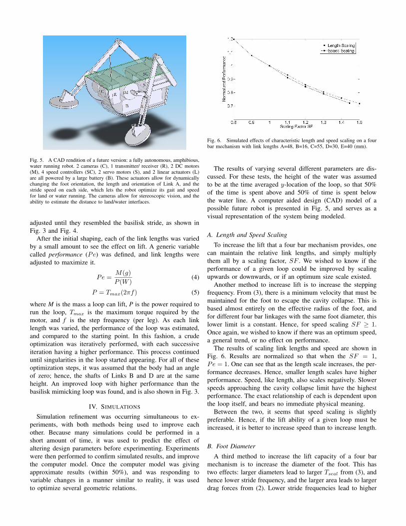
Fig. 5. A CAD rendition of a future version: a fully autonomous, amphibious,water running robot. 2 cameras (C), 1 transmitter/ receiver (R), 2 DC motors(M), 4 speed controllers (SC), 2 servo motors (S), and 2 linear actuators (L)are all powered by a large battery (B). These actuators allow for dynamicallychanging the foot orientation, the length and orientation of Link A, and thestride speed on each side, which lets the robot optimize its gait and speedfor land or water running. The cameras allow for stereoscopic vision, and theability to estimate the distance to land/water interfaces.
adjusted until they resembled the basilisk stride, as shown inFig. 3 and Fig. 4.
After the initial shaping, each of the link lengths was variedby a small amount to see the effect on lift. A generic variablecalled performance (Pe) was defined, and link lengths wereadjusted to maximize it.
Pe =M(g)P (W )
(4)
P = Tmax(2πf) (5)
where M is the mass a loop can lift, P is the power required torun the loop, Tmax is the maximum torque required by themotor, and f is the step frequency (per leg). As each linklength was varied, the performance of the loop was estimated,and compared to the starting point. In this fashion, a crudeoptimization was iteratively performed, with each successiveiteration having a higher performance. This process continueduntil singularities in the loop started appearing. For all of theseoptimization steps, it was assumed that the body had an angleof zero; hence, the shafts of Links B and D are at the sameheight. An improved loop with higher performance than thebasilisk mimicking loop was found, and is also shown in Fig. 3.
IV. SIMULATIONS
Simulation refinement was occurring simultaneous to ex-periments, with both methods being used to improve eachother. Because many simulations could be performed in ashort amount of time, it was used to predict the effect ofaltering design parameters before experimenting. Experimentswere then performed to confirm simulated results, and improvethe computer model. Once the computer model was givingapproximate results (within 50%), and was responding tovariable changes in a manner similar to reality, it was usedto optimize several geometric relations.
Fig. 6. Simulated effects of characteristic length and speed scaling on a fourbar mechanism with link lengths A=48, B=16, C=55, D=30, E=40 (mm).
The results of varying several different parameters are dis-cussed. For these tests, the height of the water was assumedto be at the time averaged y-location of the loop, so that 50%of the time is spent above and 50% of time is spent belowthe water line. A computer aided design (CAD) model of apossible future robot is presented in Fig. 5, and serves as avisual representation of the system being modeled.
A. Length and Speed ScalingTo increase the lift that a four bar mechanism provides, one
can maintain the relative link lengths, and simply multiplythem all by a scaling factor, SF . We wished to know if theperformance of a given loop could be improved by scalingupwards or downwards, or if an optimum size scale existed.
Another method to increase lift is to increase the steppingfrequency. From (3), there is a minimum velocity that must bemaintained for the foot to escape the cavity collapse. This isbased almost entirely on the effective radius of the foot, andfor different four bar linkages with the same foot diameter, thislower limit is a constant. Hence, for speed scaling SF ≥ 1.Once again, we wished to know if there was an optimum speed,a general trend, or no effect on performance.
The results of scaling link lengths and speed are shown inFig. 6. Results are normalized so that when the SF = 1,Pe = 1. One can see that as the length scale increases, the per-formance decreases. Hence, smaller length scales have higherperformance. Speed, like length, also scales negatively. Slowerspeeds approaching the cavity collapse limit have the highestperformance. The exact relationship of each is dependent uponthe loop itself, and bears no immediate physical meaning.
Between the two, it seems that speed scaling is slightlypreferable. Hence, if the lift ability of a given loop must beincreased, it is better to increase speed than to increase length.
B. Foot DiameterA third method to increase the lift capacity of a four bar
mechanism is to increase the diameter of the foot. This hastwo effects: larger diameters lead to larger Tseal from (3), andhence lower stride frequency, and the larger area leads to largerdrag forces from (2). Lower stride frequencies lead to higher

Fig. 7. Simulated effect of adjusting the foot diameter. Loop A: link lengthsA=40, B=16, C=40, D=24, E=32 (mm). Loop B: link lengths A=48, B=16,C=55, D=30, E=40 (mm). Loop C: link lengths A=50, B=20, C=40, D=40,E=40 (mm).
performance, as seen in Fig. 6, but larger drag forces willincrease both the lift and power requirements. As in the speedand length scaling cases, we wished to know if there was anoptimum foot diameter, a trend, or no effect on performance.
Fig. 7 shows that as the foot diameter is increased, theperformance also increases. Further, this effect seems to beindependent of loop shape, as demonstrated by the similarityof the normalized performance lines for all three four barlinkages. The performance scales with D0.5
F , which is logical.Examination of (2), (3) and (4), combined with the knowledgethat power scales with force multiplied by speed, one can seethe numerator of (4) scales with D2
F , and the denominatorscales with (D2
F )(D−0.5F ). Hence, to maximize performance,
increase the foot diameter. The limitations of the diameter areplaced by practical, and not theoretical constraints; determinethe largest foot diameter for a robot that is reasonable in relationto the rest of the body. In our experiments, DF = 40 (mm) forall trials.
C. Foot Angle
When the basilisk runs on water, it adjusts its foot anglethroughout the step. This maximizes the lift and thrust gener-ated, and also allows the lizard to streamline its foot during therecovery phase. For this simple device, a static foot angle ismost easily achieved when using rigid, passive components.
For initial predictions, it was assumed the foot angle wouldbe ideal throughout the loop; i.e. that the plane of the footwould be perpendicular to the velocity vector direction. Thisis not possible with a non-dynamic foot, so the program wasadjusted to incorporate a set foot angle. The angle was thenvaried to determine the optimum. Zero degrees was assumed tobe in line with Link C, and angles follow the counterclockwiseconvention.
The results of these tests are shown in Fig. 8. This is anotherloop dependent optimization, so these tests were performed onthe highest performing loop from the iteration stages. For anglesbetween -5o and 10o, there is only a slight decrease in the liftprovided. To ease assembly of prototypes, all tests were donewith 0o foot angle.
Fig. 8. Simulated effect of adjusting the foot angle. Done for link lengthsA=48, B=16, C=55, D=30, E=40 (mm).
For these tests, performance is not a useful metric because itremains nearly unchanged for each foot angle. This is logicalbecause foot angles which provide less lift require less powerto move the foot through the step path.
D. Extra LegsThroughout the simulated results, power required was taken
as the maximum torque multiplied by the speed. But, the torquerequired throughout each step varies greatly and, depending onthe loop, can even drop below zero. If an extra pair of legs isadded, phase shifted by 90o from the first pair, then it might bepossible to double the lift while only marginally increasing thepower requirements. Similar scaling will also occur if 4 morelegs are added to that. The effect to the torque can be seen inFig. 9.
After 8 legs, one enters the realm of diminishing returnswhen it comes to increasing performance. For the link lengthsA=48, B=16, C=55, D=30, E=40 (mm), two legs yields aperformance of 32 g/W, and four legs yields 55 g/W, buteight legs only lifts 58 g/W. But, it is interesting to note thatincreasing the number of legs beyond eight can increase thelift while maintaining the same performance. This implies thatthe best way to boost lift is to increase the number of legs, notscale the length or the speed. Effectively, one can decouple thespeed effects from the lift entirely, and use a speed control forboth turning and stability.
V. EXPERIMENTS
To test the simulation results, a two-legged setup, similar toFig. 10, was created. This was supported with carbon fiber -and later, acrylic - struts connected to a counter weight. Boththe mass of the test robot and the counter weight mass wereabove the fulcrum height; hence, the system was unstable, andtended to fall one way or the other. On the robot side, there wasa support under the struts, allowing the robot to rest at a slightangle with the counter weight suspended in the air. The fulcrumof this counterweighted system was placed as close as possibleto a central shaft, about which the entire assembly could revolveduring testing. A ten pound weight held the central shaft andassembly in place in a tub of water during testing.

A. Testing ProcedureFirst, the height of the input axle was measured relative to
the tub bottom as a reference point. Water was added to the tubuntil the feet of the robot could interact with it (approximately2-3 mm above the lowest point of the toe path) and the heightwas measured relative to the axle height. Then, the counterweight was moved to the point where the two bodies wereperfectly balanced with the struts are exactly horizontal. Themotor was started, and the robot was lightly held down untiltransient vibrations diminished. After letting go, if the robotpushed itself up and over the stable point, weight was addedto the robot until it could no longer push itself up. Afterward,the system was rechecked to ensure it was still in its balancedposition (which shifts as the machine gets wet). The weightwas recorded, more water was added, and the procedure wasrepeated.
To ensure that the vibrations of the motor itself did not causethe robot to push over its stable point, each four bar systemwas run after calibration while dry. This led to a large spacingbetween the fulcrum and the robot system, and a large amountof upward push required to lift it. On later trials, when excessivevibration did excite the machine over its stable point, the strutswere remade and mild damping was added.
B. DC Motor ResultsInitially, a DC motor was used to test simulated predic-
tions and refine the computer model. Testing was performedfor various loop configurations, to determine if the computeraccurately predicted more optimized loops. This motor had nospeed control, so the speed used in predicting lift was thein-air motor speed, approximately 5 Hz, determined using astroboscope. Results are shown in Fig. 11.
Because DC motors were used, the speed decreased as torqueincreased. These results showed that, while overestimating, thepredictor program had a slope similar to reality, and couldtake into account varying water levels accurately. This led toimprovement of the estimator for later trials.
C. Stepper Motor ResultsMore promising and accurate results were found when a
stepper motor was used. Because speed can be controlled with
Fig. 9. Simulated torque throughout a single revolution for 2, 4, and 8 legs.Done for Link A=40, Link B=16, Link C=40, Link D=24, Link E=32 (mm).
Fig. 10. Photo of the four legged experimental setup used for testing. Twolegged versions with variable link lengths were also used to test the accuracyof the computer models.
Fig. 11. Experimental DC motor results for three 4 bar sets. Dash-dot linesare theoretical predictions; regular lines are experimental data. Loop A: linklengths A=40, B=16, C=40, D=24, E=32 (mm). Loop B: link lengths A=40,B=16, C=32, D=32, E=32 (mm). Loop C: link lengths A=40, B=16, C=24,D=40, E=40 (mm). All tests were run at 5 Hz.
a stepper motor, more accurate information could be providedto the estimator program. One can see from Fig. 12 that theresults of experiment and theory more closely match, and themaximum lift we are getting is 17 grams at 6 Hz. For thisresult Pe = 15 g/W. These results are still much lower thanthe lift a basilisk lizard can generate, around 34 g/W [7]. Theseexperiments were carried out on a high performance loop whilevarying the motor speed.
D. Four Legged ResultsAs mentioned in Section IV, simulation results implied four
legs would have a higher performance than two legs. As such,the experimental setup shown in Fig. 10 was used. This wasonce again driven by a DC motor without speed control,because of the higher power ratings and the ease of installation.Using a scaled up version of a high performance loop, the frontand back legs are driven at the same speed, offset by 90o. Theresults of testing are shown in Fig. 13.
The four legged results are, in appearance, similar to the twolegged DC motor results. This implies that if a powerful, speedcontrolled motor is used, the lift curve should resemble the twolegged stepper motor results, in Fig. 12, and the theoretical andexperimental lifts would converge. The maximum lift provided
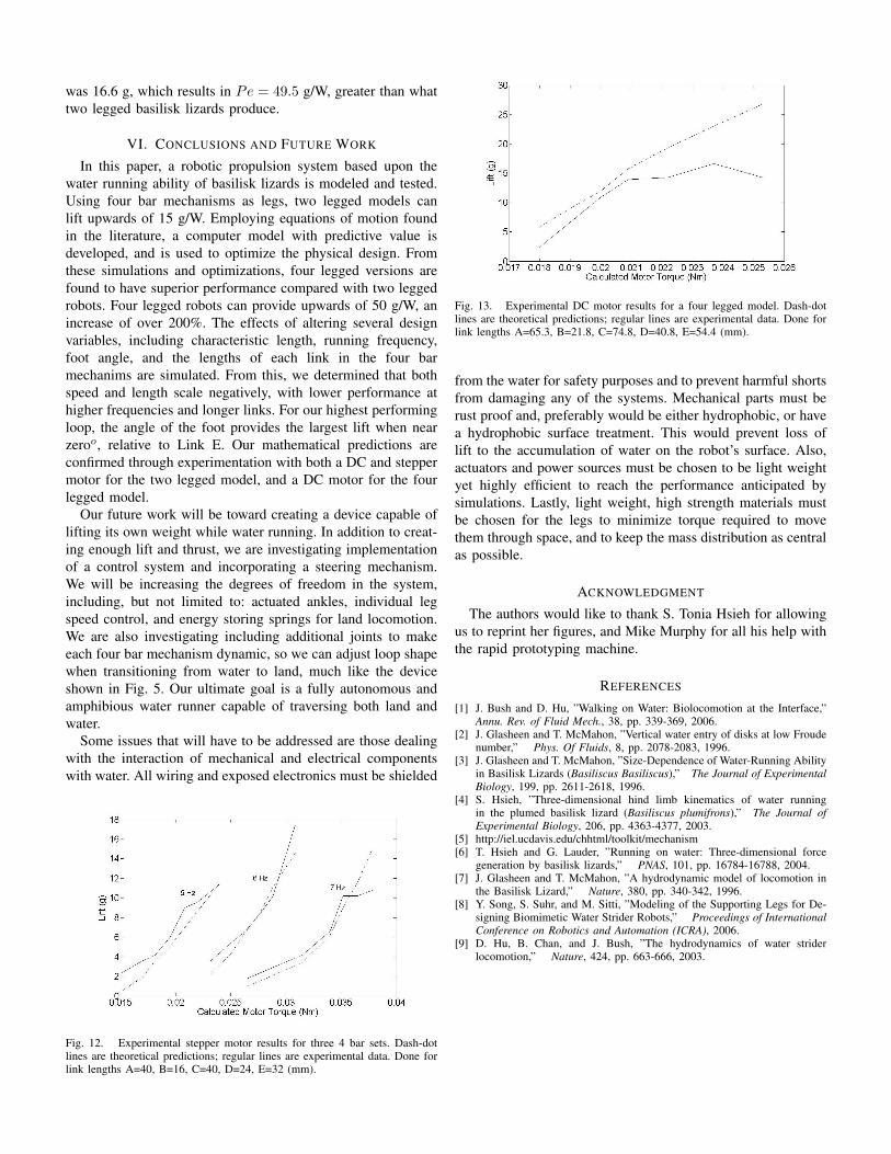
was 16.6 g, which results in Pe = 49.5 g/W, greater than whattwo legged basilisk lizards produce.
VI. CONCLUSIONS AND FUTURE WORK
In this paper, a robotic propulsion system based upon thewater running ability of basilisk lizards is modeled and tested.Using four bar mechanisms as legs, two legged models canlift upwards of 15 g/W. Employing equations of motion foundin the literature, a computer model with predictive value isdeveloped, and is used to optimize the physical design. Fromthese simulations and optimizations, four legged versions arefound to have superior performance compared with two leggedrobots. Four legged robots can provide upwards of 50 g/W, anincrease of over 200%. The effects of altering several designvariables, including characteristic length, running frequency,foot angle, and the lengths of each link in the four barmechanims are simulated. From this, we determined that bothspeed and length scale negatively, with lower performance athigher frequencies and longer links. For our highest performingloop, the angle of the foot provides the largest lift when nearzeroo, relative to Link E. Our mathematical predictions areconfirmed through experimentation with both a DC and steppermotor for the two legged model, and a DC motor for the fourlegged model.
Our future work will be toward creating a device capable oflifting its own weight while water running. In addition to creat-ing enough lift and thrust, we are investigating implementationof a control system and incorporating a steering mechanism.We will be increasing the degrees of freedom in the system,including, but not limited to: actuated ankles, individual legspeed control, and energy storing springs for land locomotion.We are also investigating including additional joints to makeeach four bar mechanism dynamic, so we can adjust loop shapewhen transitioning from water to land, much like the deviceshown in Fig. 5. Our ultimate goal is a fully autonomous andamphibious water runner capable of traversing both land andwater.
Some issues that will have to be addressed are those dealingwith the interaction of mechanical and electrical componentswith water. All wiring and exposed electronics must be shielded
Fig. 12. Experimental stepper motor results for three 4 bar sets. Dash-dotlines are theoretical predictions; regular lines are experimental data. Done forlink lengths A=40, B=16, C=40, D=24, E=32 (mm).
Fig. 13. Experimental DC motor results for a four legged model. Dash-dotlines are theoretical predictions; regular lines are experimental data. Done forlink lengths A=65.3, B=21.8, C=74.8, D=40.8, E=54.4 (mm).
from the water for safety purposes and to prevent harmful shortsfrom damaging any of the systems. Mechanical parts must berust proof and, preferably would be either hydrophobic, or havea hydrophobic surface treatment. This would prevent loss oflift to the accumulation of water on the robot’s surface. Also,actuators and power sources must be chosen to be light weightyet highly efficient to reach the performance anticipated bysimulations. Lastly, light weight, high strength materials mustbe chosen for the legs to minimize torque required to movethem through space, and to keep the mass distribution as centralas possible.
ACKNOWLEDGMENT
The authors would like to thank S. Tonia Hsieh for allowingus to reprint her figures, and Mike Murphy for all his help withthe rapid prototyping machine.
REFERENCES
[1] J. Bush and D. Hu, ”Walking on Water: Biolocomotion at the Interface,”Annu. Rev. of Fluid Mech., 38, pp. 339-369, 2006.
[2] J. Glasheen and T. McMahon, ”Vertical water entry of disks at low Froudenumber,” Phys. Of Fluids, 8, pp. 2078-2083, 1996.
[3] J. Glasheen and T. McMahon, ”Size-Dependence of Water-Running Abilityin Basilisk Lizards (Basiliscus Basiliscus),” The Journal of ExperimentalBiology, 199, pp. 2611-2618, 1996.
[4] S. Hsieh, ”Three-dimensional hind limb kinematics of water runningin the plumed basilisk lizard (Basiliscus plumifrons),” The Journal ofExperimental Biology, 206, pp. 4363-4377, 2003.
[5] http://iel.ucdavis.edu/chhtml/toolkit/mechanism[6] T. Hsieh and G. Lauder, ”Running on water: Three-dimensional force
generation by basilisk lizards,” PNAS, 101, pp. 16784-16788, 2004.[7] J. Glasheen and T. McMahon, ”A hydrodynamic model of locomotion in
the Basilisk Lizard,” Nature, 380, pp. 340-342, 1996.[8] Y. Song, S. Suhr, and M. Sitti, ”Modeling of the Supporting Legs for De-
signing Biomimetic Water Strider Robots,” Proceedings of InternationalConference on Robotics and Automation (ICRA), 2006.
[9] D. Hu, B. Chan, and J. Bush, ”The hydrodynamics of water striderlocomotion,” Nature, 424, pp. 663-666, 2003.


![Shape memory alloy-based small crawling robots inspired by ... · material for many biologically inspired robots such as worm-like robots [12], the bending actuation of an IPMC is](https://img.pdfslide.us/doc/110x75/5fbd02e298ad5d4fd41f1ccb/shape-memory-alloy-based-small-crawling-robots-inspired-by-material-for-many.jpg)


![Asimov,Isaac [Robots] (1950) Les robots (I, robot)](https://img.pdfslide.us/doc/110x75/5571f9a34979599169900ec4/asimovisaac-robots-1950-les-robots-i-robot.jpg)