Embed Size (px)
Citation preview

IEEE TRANSACTIONS ON ELECTRON DEVICES, VOL. ED-27, NO. 11, NOVEMBER 1980 2063
vol. 125, p. 819,1978. [ 101 S. M. Sze, Physics of Semiconductor Devices. New York: Wiley- [7] T. I. Kamins,J. Appl. Phys., vol. 42,p. 4357, 1971. Interscience, 1969, ch. 11. [8] G. Baccarami, B. Ricco, and G. Spadini, J. Appl. Phys., vol. 49, [ 111 M. Hamasaki, T. Adachi, S. Wakayama, and M. Kikuchi, Solid
p. 5565,1978. State Commun.,vol. 21,p. 591,1977, [9] G. J. Korsh and R. S. Muller, Solid State Electron., vol. 21, p. [ 121 N. Zommer, M.S.C. thesis, Tel Aviv University, Tel Aviv, Isreal,
1045,1978. 1973, and J . Jortner and M. H. Cohen private communication.
A Novel Type of Inverted Dichroic Display Employing a Positive Dielectric Anistropy Liquid Crystal
FEREYDOUN GHARADJEDAGHI AND ERIC SAURER
Abstract-Two versions of a novel dichroic guest-host liquid-crystal display are described which exhibit positive contrast and employ an optically active material, an dichroic dye, and a positive dielectric aniso- tropy nematic liquid crystal.
The working principle is based on the fact that in the area outside the digits, critical conditions are established which prevent the formation of a cholesteric helicoidal structure. This gives rise to a homeotropic structure and, therefore, a transparent state. In the off state the digits appear colored on a bright background. In both cases electrooptic behavior and response times are compared to the normal negative con- trast guest-host system described by White and Taylor.
I. INTRODUCTION
I N a mixture of a liquid crystal and a dichroic dye, the collec- tive orientation of the liquid-crystal molecules under the
action of an electric field influences that of the dye molecules. This phenomenon (called the guest-host interaction and demonstrated in 1968 by Heilmeier et al. [ I ] , [2]) can be used to make a display device. The cell described by these authors used a mixture of a positive dielectric anisotropy (Ae > 0), nematic liquid crystal, and a dichroic dye. This cell has good contrast only if planar molecular alignment is used in conjunction with a polarizer. The type of display obtained is a clear digit on a colored background (negative contrast).
More recently (1974), White and Taylor [3] have proposed a new cell of the guest-host type consisting of a mixture of a nematic liquid crystal (Ae > 0), a chiral component, and a dichroic dye. In this case, the cholesteric to nematic phase transition, induced by an electric field, is employed. In the absence of an electric field, the helicoidal structure of the mixture has the property of absorbing the two components of nonpolarized light, permitting the cell to operate without a polarizer. In addition, no specific alignment of the molecules on the surface is necessary. Perpendicular alignment, however,
Manuscript received December 7, 1979; revised May 19, 1980. The authors are with Central R and D Laboratories of the ASUAG
group, NeuchOtel, Switzerland.
allows lower operating voltages to be obtained. This cell, like the Heilmeier cell, has negative contrast, but with the addi- tional advantage of higher digit brightness, due to the absence of the polarizer.
It is possible to obtain a positive contrast cell (dark digits on a clear background) by using either a pure nematic liquid crystal with negative anisotropy (Ae < 0) and perpendicular alignment, or to greater advantage, by adding a chiral com- pound to the nematic liquid crystal and employing a cell thickness such as to give rise to a homeotropic structure in the off state and to a helicoidal structure in the on state [4] . Both solutions, however, have the disadvantages characteristic of negative Ae liquid crystals, i.e.:
The operating voltage is relatively high since existing materials possess a weak dielectric anisotropy.
The driving frequency must be set at a high value to avoid electrohydrodynamic phenomena, if the mixture resistivity is not high enough.
In the case of a cell of the White-Taylor (W-T) type, it is possible to display dark digits on a clear background by driving all the surface complementary to the segments to be displayed [5] . Such a display would have a rather highcurrent consumption.
A novel type of guest-host cell is presented in this work, using a mixture of the same type as that used by White and Taylor but with the following advantages:
positive contrast; lower consumption; a large multiplexing capacity for one of the described con- figurations (cell 2).
11. OPERATING PRINCIPLE The molecular structure of a layer composed of a liquid
crystal and a chiral agent is determined both by the type of molecular alignment on the substrate surfaces and by the thick- ness d of the liquid layer. If this thickness is sufficiently large, the structure is always helicoidal in the bulk of the layer, re- gardless of the surface alignment.
0018-9383/80/1100-2063$00.75 0 1980 IEEE

2064 IEEE TRANSACTIONS ON ELECTRON DEVICES, VOL. ED-27, NO. 11 , NOVEMBER 1980
With homeotropic alignment on the two substrates, there is a critical layer thickness d, below which the structure of the layer is homeotropic throughout its thickness [6] , [7] .
This critical thickness, calculated by Greubel [6] , is given by the expression d, = PK33/2K22 where P is the pitch of the helicoidal structure of the unconstrained mixture and Kz2 and K33 are the two elastic constants corresponding to twist and bend deformations, respectively.
Two versions of a cell using this property are proposed. The operating principle of both cells is based on the fact that in the zone situated outside the digits, the prevailing conditions result in a homeotropic structure (homeotropic alignment on the two substrates and d < d,) and that these conditions do not exist in the digit areas (alignment nonhomeotropic anlor d >d,) . Thus the digits appear colored (helicoidal structure) on a clear background (homeotropic structure) in the absence of an electric field. When an electric field is applied, the heli- coidal structure is destroyed and the molecules of the mixture adopt a homeotropic structure with the result that only the nonactivated digit areas remain dark. Thus the control logic for this type of display is inverted with respect to that required for cells of the W-T type with negative contrast.
111. TECHNICAL DESCRIPTION
A. Cell 1 As shown in Fig. 1, a homeotropic alignment layer completely
covers the surface of one substrate while it covers only the areas outside the digits on the other substrate. The molecular alignment is parallel to the surface in the digit areas and the cell thickness is smaller than the critical thickness d,. Although the addition of a chiral component to the mixture is not neces- sary, its use improves the contrast (see experimental section and Appendix). Note also that if the driving voltage is not high enough to induce perfectly homeotropic alignment, a residual contrast will exist between activated areas and the display background. This residual contrast can be compensated for by depositing an absorbing layer on the areas outside the digits, giving them a slightly colored tint.
B. Cell 2 The alignment is homeotropic over all the surface of both
substrates (see Fig. 2 ) but the cell thickness is less than the critical value outside the digit areas (dl < d,) and larger than this value inside these areas (d, > d,).
In the digit areas, the electrooptic response is very similar to a W-T cell with homeotropic boundary conditions. The struc- ture in the digit areas of these two cells being exactly the same, the contrast between the off and the on states will be also the same, as will the response times, to, and t,ff. The only differ- ence is in the memory effect (bistable behavior) [6] , [8] , [9] , which as shown in the experimental section, is clearly more accentuated in the case of cell 2.
This memory effect is observed when the driving voltage, previously higher than the critical voltage (6) for the choles- teric-nematic transition, drops below this value. The nematic state in this case is a metastable state. In practice, with a W-T
Fig. 1. Cross section of cell 1. a) Transparent electrode, b ) perpendicu- lar alignment layer, and c) parallel alignment layer.
(a) Fig. 2. Cross section of cell 2. a) Transparent electrode and b ) perpen-
dicular alignment layer.
cell, nucleation phenomenon progressively allows the focal conic structure to grow from the electrode edges (the boundary between nematic and cholesteric structures) and from surface defects [9] . In the case of cell 2, since nematic cholesteric boundaries do not exist in the excited state, nucleation can only start at surface defects.
Due to the difference in thickness between the excited areas and the background, cell 2 exhibits a voltage-independent residual contrast which must be compensated for by an ab- sorbing layer in the areas outside the segments.
N. EXPERIMENTAL WORK The experimental results presented here demonstrate:
the role of the chiral component in the electrooptic behavior of cell 1 ; the electrooptic behavior of cell 1 as compared to the W-T cell and cell 2 ; the memory effect of cell 2 compared to that of the W-T cell.
For these comparisons, low voltage W-T type cells (6 N 3 V, d/P"- 2 ) with homeotropic alignment on the two surfaces were used. This choice is not optimal regarding the contrast and the decay times but is an interesting one for watch display applications.

GHARADJEDAGHI AND SAURER: A NOVEL TYPE OF INVERTED DICHROIC DISPLAY 2065
C-C cross section
D-D cross section
Trans.arent< Z& \Zone B )Bottomdass electrode ---H.imm
Fig. 3. Experimental cell for the study of the influence of different structures at electrode borders.
A. Experimental Conditions The transmission measurements were made on a Leitz
Orthoplan-Pol microscope in monochromatic light with a wavelength corresponding to the absorption peak of the di- chroic dye employed (X = 492 nm). The luminous intensity was detected by a photomultiplier (RCA 1P21) fitted to the microscope. The numerical aperture of the optical system was less than 0.22. In every case the liquid crystal used was TN 103 (Hoffmann La Roche), the chiral component was CB15 (BDH), and the dichroic dye was D2 (BDH). Cell thickness was determined by transmissive interference measurements.
For the measurements on cell 1, two experimental cells with different thicknesses (d = 6.3 pm and 8.5 pm) were used. The substrates were covered with an alignment layer, one side being SiO, (evaporated at oblique incidence) giving parallel molecu- lar alignment [ lo] , the other, a layer of Zr02 (evaporated at near normal incidence) inducing homeotropic alignment’.
After treatment with a surfactant (lecithin), which induced homeotropic alignment on both plates, the same cells were used for relative measurements on the W-T cell. Thus the com- parative measurements between the W-T cell and cell 1 were done under identical experimental conditions.
The measurements showing the difference in memory-effect behavior between cell 2 and the W-T cell, were made on the experimental cell illustrated in Fig. 3. This cell allowed the study of different structures at the electrode edges. In ZoneA, the structure at the edges was homeotropic (as in the case of cell 2) due to the fact that in one part or the other of this zone the layer thickness was less than the critical thickness d,. In Zone B , on the other hand, the cholesteric structure dominated at the edges, as in the case of the W-T cell. A comparative study between the Zones A and B was made by measuring the variation of transmission with time from the instant when the voltage dropped from a high value VH to a value V, less than the critical voltage 6 . The reduction in transmission corre- sponded to the surface’s “invasion” by the focal conic structure
Y. Ruedin, work accomplished in our laboratory.
O ’ l i i 4 5 6 7 i Volts (rms)
Fig. 4. Transmission as a function of increasing voltage: case of cell 1. ( T I I ) , ( T I : ) , (TI), and ( T i ) : polarized light parallel or perpendicular to the direction of planar alignment. ( T ) and ( T ‘ ) : unpolarized light. Mixtures (wt %): TN 103 + D2 (1 percent) + CB 15 (2 percent). (Pitch P = 7 pm) for ( T I ) , (TI), and (T) . TN 103 + D2 (1 percent) for (T i ) , (Ti), and (T’ ) , dell thickness: d = 6.3 pm, wavelength: h = 492 nm.
Volts (rmrj Fig. 5. Transmission as a function of increasing voltage: case of cell 1
( T I I ) , ( T i ) , (T l ) , and ( T i ) : polarized light parallel or perpendicular to the dlrection of the planar alignment. ( T ) and ( T ’ ) : unpolarized light. Mixtures (wt %): TN 103 + D2 (1 percent) + CB 15 (1.56 per- cent). (Pitch P = 9 pm) for (T ), (TI ) , and T - TN 103 + D2 (1 per- cent) for (Til), (Ti), and (T’ ) . (!!ell thickness; d = 8.5 pm, wavelength: A = 492 nm.
absorbing the light. The region measured included the nematic- cholesteric interface when the cell was excited.
B. Experimental Results-Discussion The transmission-voltage characteristics for cell 1 are pre-
sented in Figs. 4 and 5 . Two cells of different thickness were

2065 IEEE TRANSACTIONS ON ELECTRON DEVICES, VOL. ED-27, NO. 1 1 , NOVEMBER 1980
used for each of two mixtures, the first containing a chiral component (see curves 7‘11, TL, and T ) the other without it (see ?/, Ti, and T’) . The curves (TII), (q/), (TJ, and (Ti) correspond to the characteristics obtained with light polarized parallel (7‘11, ?{) or perpendicular (Tl, T i ) to the direction of the planar alignment and with the light incident on the substrate with planar alignment. Obtained from the preceding curves, the curves (7‘) and (2‘’) give the transmission of the cell for nonpolarized light. For the two polarization cases, the intro- duction of the chiral component results in an increase in the absorption of the medium when in the nonactivated state (7‘1 < Ti, Tll < q{). This result is discussed further.
Consider a cell where the alignment direction is planar on the substrates and parallel between them; such a cell, filled with a mixture of a nematic liquid crystal and a dichroic dye, confers a homogeneous planar structure to the mixture, This system has two coefficients of attenuation ctl and all which are independent of the point considered. These coefficients correspond to the cases where the incident illumination is polarized, respectively, perpendicular and parallel to the align- ment direction on the two substrates. Suppose now that the alignment conditions in the segment areas of the cell are those of cell 1, and that it is filled with a mixture of the mentioned type. In this case, the structure of the mixture is such that the director varies from being parallel to one substrate to being perpendicular to the other, but remaining fixed in a plane defined by the two alignment directions. At each point, distance z from the planar aligning substrate, two attenuation coefficients ctl (z) and az(z) can be defined, such that a1 (z) = orl and aZ (z) < all. The inequality arises from the fact that the molecular tilt angle e@), with respect to the substrates, is always nonzero, except in the case where z = 0. The trans- mission in this case is given by Ti and ?/. If, in addition, the mixture contains a chiral component, and the alignment con- ditions are those of cell 1, the system will adopt a helicoidal structure. Under these conditions, the director at each point can be defined by two angles e(z) (tilt) and $(z) (azimuth). With the exception of special cases where wave guiding occurs (i.e., cases where the direction of linear polarization is given by the function e@)), this type of structure changes incident linearly polarized light into elliptically polarized light. Under these conditions, Tl and Til refer to the two directions of polarization of the incident light, and it is evident that TJ. < TL. If it is assumed that at each point in the system the tilt angle O(z) is equal to, or greater than the corresponding tilt angle of the system without a chiral component, the previous remarks on the propagation of light through a cholesteric medium imply that Tll > ?{. Experimental results indicate, however, that Tll < q;. The preceding hypothesis is, therefore, incorrect. This result is also confirmed by the calculations given in the Appendix. The numeric results obtained indicate that in the case where the system contains a chiral component, the tilt angle B(z) at all points is less than or equal to the tilt angle of the corresponding point in a system without this component. The difference in tilt angles is sufficiently large to compensate for the reduction in the absorption due to the change in the state of polarization (linear to elliptical). These experimental and numerical results demonstrate the role of the chiral component in improving the contrast.
TABLE I ELECTROOPTICAL STATIC AND DYNAMIC MEASUREMENTS OF CELL I-THE MONOCHROMATIC CONSTANT IS DEFINED BY C = T,, - Zfr/ T,, X 100, WHERE To, AND T o r r DENOTE THE TRANSMISSION OF THE CELL FOR A =
492 nm. RESPONSE TIMES ton AND torr CORRESPOND TO A 90-PERCENT VARIATION OF THE OPTICAL TRANSMISSION.
Experimental Conditions I I
Mono- chromatic
contrast
-=-K 4 V rms 4Vrms
32 20
48 27
35 23
6Vrms
I
I TABLE I1
ELECTROOPTICAL STATIC AND DYNAMIC MEASUREMENTS OF THE W-T CELL (SAME AS CELL 2). FOR THE DEFINITION OF THE
PARAMETERS SEE TABLE I. I I I
-7 Mixtures
[Experimental Conditions Mono- ON OFF chromatic contrast
- - (ms)
(V. 0) V33.5Vrms 4Vrms 6Vrms
~
TN103+D2(1%) +CB15(3.35%)
I
In Table I, response time and contrast results for cell 1 are presented. These results can be compared to those obtained for the W-T cell and are presented in Table 11.
Fig. 6 shows the partial transmission-voltage characteristics for two W-T cells of different thicknesses and for nonpolarized light. Each of the curves was obtained by averaging the mea- surements corresponding to two rectilinear orthogonal polariza- tions and these characteristics can be compared to those of cell 1, i.e., curves ( T ) and (T ‘ ) of Figs. 4 and 5 .
Static and dynamic results for the W-T cell are given in Table 11. These results, as previously indicated, are equally represen- tative of cell 2.
The storage time of the memory effect (memory time) as a function of the “sustaining” voltage V, ( V , < V,), for the Zones A and B of the cell illustrated in Fig. 3 , are given in Fig. 7. This time is defined as the time taken for the trans- mission to be reduced by 10 percent from the instant when the voltage drops from a value V, > V,. As indicated pre- viously, this reduction in transmission is due to the growth of the focal conic structure in the electrode area. The results in

GHARADJEDAGHI AND SAURER: A NOVEL TYPE OF INVERTED DICHROIC DISPLAY 2067
*i -Zone B
L : 1 2 8 4 5 6 7 8
Volts ( rms)
Fig. 6. Transmission as a function of increasing voltage: case of a W-T cell (same as cell 2). (T,) - Mixture (wt %): TN 103 + D2 (1 percent) + CB 15 (4.3 percent). (Pitch: P = 3.28 pm), cell thickness: d = 6.3 pm. (Tb) - Mixture (wt %): TN 103 + D2 (1 percent) + CB 15 (3.35 per- cent). (Pitch: P = 4.2 pm), cell thickness: d = 8.5 pm. Unpolarized light - wavelength: A = 492 nm.
Fig, 7. Memory time as a function of “sustaining” voltage (d/P = 1.85, V, = 3.2 V rms).
Fig. 7 shown that the memory time is clearly longer in Zone A and the role of the homeotropic structure at the borders of Zone A is shown. In the case of Zone B, the structure at the extremes is focal conic.
Another illustration of the role of the conditions at the borders is given in Fig. 8. This photograph is an enlargement of a region of the experimental cell, described in Fig. 3, where the two types of conditions at the edges can be seen. This figure corresponds to an instant where the focal conic structure has already grown into Zone B from the electrode edges, while no nucleation has been induced at the homeotropic structure boundary.
/Wall-Boundary limlt : homeotropic structure
Fig. 8. Photograph showing the effect of different boundary conditions on the nucleation of the conic focal structure. The cell is viewed between cross polarizers. Magnification X 42.
V. CONCLUSION Two types of positive contrast dichroic displays have been
described, both of which employ a mixture of positive dielec- tric anisotropy and have low operating voltages.
The first version, cell 1, exhibits a lower contrast but faster rise time than the W-T cell. This work enabled, in a quantita- tive manner, the effect of the chiral component on the display contrast to be demonstrated.
The second cell to be proposed, cell 2, has identical charac- teristic to the W-T cell, with the exception of the memory time, which as the experimental results have indicated, is much longer for cell 2 than for the W-T cell. In practice, this cell is an improvement on the W-T cell in applications where the addressing technique takes advantage of the memory effect. In multiplexed applications, the ratio of the writing time (corresponding to complete nematic texture switching) and/or erase time (corresponding to focal-conic switching) to the memory time are important in determining the number of digits which can be multiplexed. The memory time determines the maximum time between successive refresh cycles. Cell 2 has, therefore, a potentially larger multiplexing capability than the W-T cell, the capability of the former being essentially limited by nucleation phenomena induced by surface defects.
APPENDIX
THE ABSENCE OF AN ELECTRIC FIELD Assuming that the cell thickness .is d, and that 0, x, y , z is
a right-handed Cartesian coordinate system (Fig. 9), with 0-x parallel to the planar alignment direction. Further,n is defined as the unit vector in the direction of the local optical axis at each point in the medium. The elastic-free energy per unit area is, therefore, given by
ANGULAR CONFIGURATION OF THE LC MOLECULES IN
G = 1 ld [Kll (div n)2 t Kz2 (n * rot n t q)2
t K33 (n X rot n)2 ] dz (1)
where K l l , K z 2 , and K33 are, respectively, the relative elastic constants for deformations of splay, twist, and bend. The
2068 IEEE TRANSACTIONS ON ELECTRON DEVICES, VOL. ED-27, NO. 11, NOVEMBER 1980
t
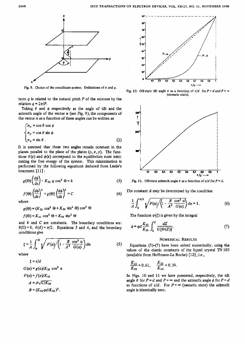
Fig. 9. Choice of the coordinate system. Definitions of e and @. =/d -
Fig. 10. Off-state tilt angle e as a function of z/d for P = d and P = - (nematic state).
term q is related to the natural pitch Y of the mixture by the relation q = 2 4 P .
Taking 8 and @ respectively as the angle of tilt and the azimuth angle of the vector n (see Fig. 9), the components of the vector n as a function of these angles can be written as
{ n, = cos 8 cos @
n,, = cos 8 sin @
n , = s i n 8 , (2 ) It is assumed that these two angles remain constant in the I planes parallel to the plane of the plates (o,x,y) , The func- I
I tions 8(z) and @(z) correspond to the equilibrium state mini- I mizing the free energy of the system. This minimization is I
I performed by the following equations deduced from Leslie's I treatment [ 1 11 : 0,l 0,2 03 04 03 46 47 0,E 98 1
Z/d - g(0) (2) - Kzz q cos2 0 = k (3) Fig. 11. Off-state azimuth angle 8 as a function of z/d for P = d .
f(0) = K l l cos2 0 t K33 sin2 0 The function @({) is given by the integral
and k and C are constants. The boundary conditions are: O(0) = 0, 8(d) = n/2. Equations 3 and 4, and the boundary @ = qd - conditions give
NUMERICAL RESULTS Equations (5)-(7) have been solved numerically, using the
values of the elastic constants of the liquid crystal TN 103 (available from Hoffmann-La Roche) [12] , i.e.,
-- K 1 l - 0.61, - K2z -0.39. - K33 K33
In Figs. 10 and 11 we have presented, respectively, the tilt angle 8 for P = d and P = 00 and the azimuth angle @ for P = d as functions of z / d . For P = 00 (nematic state) the azimuth angle is identically zero.

IEEE TRANSACTIONS ON ELECTRON DEVICES, VOL. ED-27, NO. 11, NOVEMBER 1980 2069
ACKNOWLEDGMENT
The authors wish to thank the staff of the technology group for their helpful assistance and R. Doriguzzi for his technical help.
REFERENCES
[ 11 G. H. Heilmeier and L. A. Zanoni, “Guest-host interactions in nematic liquid crystals. A new electrooptic effect,” Appl. Phys. Lett., vol. 13, pp. 91-92, Aug. 1968.
[ 21 G. H. Heilmeier, J. A. Castellano, and L. A. Zanoni, ‘‘Guest-host interactions in nematic liquid crystals,” Mol. Cryst. Liq. Cryst.,
[3] D. L. White and G. N. Taylor, “New absorptive mode reflective liquid crystal display device,” J. Appl. Phys., vol. 45, pp. 4718- 4723, Nov. 1974.
V O ~ . 8, pp. 293-304,1969.
[4] F. Gharadjedaghi, Swiss patent application 1272/78, Feb. 1978. [5] T. J. Scheffer and J. Nehring “Guest-host display,” presented at
the Symposium on Liquid Crystal Devices, IBM Research Labora-
tory, San Jose, CA, 1978. [ 61 W. Greubel, “Bistability behaviour of texture in cholesteric liquid
crystals in an electric field,” Appl. Phys. Lett., vol. 25, pp. 5-7, July 1974.
[7] M. Brehm, H. Finkelmann, and H. Stegemeyer “Orientierung cholesterischer Mesophasen an mit Lecithin behandelten Ober- flachen,” Ber. Bunsenges., vol. 78, pp. 883-886,1974.
[8] T. Ohtsuka, M. Tsukamoto, and M. Tsuchyia, “Liquid crystal matrix displays,” Japan. J . Appl. Phys., vol. 12, pp. 371-378, 1973.
[9] K. H. Walter and H. H. Kriiger, “Speichereffekte in cholester- inischen Fltissigkeiten,” Ber. Bunsenges., vol. 78, pp. 912-914, 1974.
[ 101 J. L. Janning, “Thin film surface orientation for liquid crystals,” Appl. Phys. Lett., vol. 21, pp. 173-174,1972.
[ 111 F. M. Leslie, “Distorsion of twisted orientation patterns in liquid crystals by magnetic fields,” Mol. Cryst. and Liq. Cryst., vol. 12,
[ 121 M. Schadt, F. Muller, “Physical properties of new liquid crystal mixtures and electrooptical performance in twisted nematic display,” IEEE Trans. Electron Devices, vol. ED-25, pp. 1125- 1137, Sept. 1978.
pp. 57-72,1970.
Mechanically Bistable Liquid-Crystal Display Structures
Abstract-This paper discusses two types of mechanically bistable liquid-crystal display structures, a previously reported type [2], [3] called vertical-horizontal, and a second type, called horizontal- horizontal. In both of them, the director configuration is planar. They are distinguished by the orientation of the director plane, which is per- pendicular to the major surfaces of the device in the type called vertical- horizontal, and parallel in the type called horizontal-horizontal. In both types, the bistable states may be differentiated optically by use of a polarizer and dichroic dye, and switching is accomplished elec- trically by exploiting the dielectric anisotropy of the ordered liquid crystal states. We show calculations of the director configurations, their energy, and optical contrast of the bistable states.
The bistable states are topologically distinct, so that the switching transitions are necessarily discontinuous in character. The movement of disclinations governs the switching process, and their detachment forms the basis of stability.
Manuscript received February 20,1980; revised May 27,1980. The authors are with Bell Laboratories, Holrndel, NJ 07733.
M I. INTRODUCTION
ECHANICALLY BISTABLE liquid-crystal structures are potentially useful as elements in displays. Although
conventional liquid-crystal twist cells [ l ] have found impor- tant applications, they lack the desirable feature of power-off memory that mechanical bistability can provide. A mechani- cally bistable structure is one in which the liquid-crystal director can assume either of two different ordered stable con- figurations of equal or nearly equal energy. Displays based on mechanical bistability have been disclosed by Boyd, Cheng, and Ngo [2], [3] and by Berreman and Heffner [4].
A toggle switch is an example of a mechanical system that is bistable. The switch stays in either position without having to be held. Both equilibrium configurations are stable, since an energy barrier must be overcome to pass from one to the other.
0018-9383/80/1100-2069$00.75 0 1980 IEEE