Embed Size (px)
Citation preview
February 18, 2015 23:9 WSPC/INSTRUCTION FILE S9˙mey
International Journal of Modern Physics: Conference Series© The Authors
A Novel RF E × B Spin Manipulator at COSY
Sebstian Mey∗† and Ralf Gebel∗ on behalf of the JEDI Collaboration
∗ Institut fur Kernphysik, Forschungszentrum Julich, Wilhelm-Jonen-Str., 52425 Julich,
Germany† III. Physikalisches Institut B, RWTH Aachen, Otto-Blumenthal-Str., Aachen, 52074, Germany
Received February 18, 2015
The Julich Electric Dipole Moment Investigations (JEDI) Collaboration is developingtools for the measurement of permanent Electric Dipole Moments (EDMs) of charged,
light hadrons in storage rings. While the Standard Model prediction for the EDM givesunobservably small magnitudes, a non-vanishing EDM from CP violating sources beyond
the standard model can lead to a tiny build-up of vertical polarization in a beforehand
horizontally polarized beam. This requires a spin tune modulation by an RF dipolewithout any excitation of coherent beam oscillations. In the course of 2014, a prototype
RF E × B dipole has been successfully commissioned and tested. We verified that the
device can be used to continuously flip the vertical polarization of a 970 MeV/c deuteronbeam without exciting any coherent beam oscillations.
Keywords: Electric dipole moment; Storage rings; Spin dynamics
PACS numbers:13.40.Em, 11.30.Er, 29.20.db, 29.27.Hj
1. RF Wien-Filter for EDM Experiments
The motion of a relativistic particle’s spin in an electromagnetic storage ring (~β · ~B =~β · ~E = 0) with non vanishing EDM contributions is given by the generalized Frenkel-
Thomas-BMT Equation1, d~S/dt = ~S × ~Ω, with
~Ω =q
m
((1 + γG) ~B −
(γG+
γ
γ + 1
)~β ×
~E
c
)︸ ︷︷ ︸
=:~ΩMDM
+q
m
η
2
(~E
c+ ~β × ~B
)︸ ︷︷ ︸
=:~ΩEDM
. (1)
Here the anomalous magnetic moment G is given by the particle’s Magnetic Dipole
Moment (MDM), ~µ = 2(G+1) q~2m~S. This corresponds to G = −0.142 for deuterons.
As an analogue, the dimensionless factor η describes the strength of the particles
permanent EDM relative to its MDM. For a Standard Model prediction of d =
η q~2mc
~S ≈ 10−30 e cm its value is η ≈ 10−15.
This is an Open Access article published by World Scientific Publishing Company. It is distributedunder the terms of the Creative Commons Attribution 3.0 (CC-BY) License. Further distribution
of this work is permitted, provided the original work is properly cited.
1
February 18, 2015 23:9 WSPC/INSTRUCTION FILE S9˙mey
2 S. Mey & R. Gebel
In a purely magnetic storage ring, all the terms containing electric fields in Eq. 1
vanish and the EDM contribution due to the interaction with the motional electric
field (~β × ~B) will lead to a tiny tilt of the spins precession axis. This leads to a
very slow oscillation of the vertical polarization of the circulating beam, but for
η ≈ 10−15 its contribution is far below measurable.
A resonant excitation with a radial electric field oscillating on the spin precession
frequency would lead to a linear build-up of a vertical component in a horizontally
polarized beam, but any RF E field strong enough to yield measurable results
would also induce coherent transverse beam oscillations. Therefore a new approach
has been proposed.2 Instead of using a radial RF E dipole, the accelerator’s lattice
is supplemented with an RF Wien-Filter. According to Eq. 1, the Lorentz force
cancellation ~E/c = −~β × ~B means that the device will not influence the EDM
directly. It does, however, modulate the horizontal spin precession by means of
a phase kick in every turn. Together with the interaction of the EDM with the
motional electric field in the rest of the ring, this frequency modulation is able to
rotate the spin around the radial axis. The accumulation rate of an EDM signal is
then the same as in the Rabi -type excitation with an radial electric RF dipole.3
2. Setup of the Prototype
While the above described approach could provide a measurable EDM signal, it
doesn’t yield a clear observable to characterize the RF Wien-Filer itself. Therefore,
a first prototype has been commissioned at the Cooler Synchrotron4 (COSY) in
Julich, Germany, where a radial magnetic field ( ~B = (Bx, 0, 0)T ) is compensated
by a vertical electric field ( ~E = (0, Ey, 0)T ). In this configuration, the dipole fields
directly apply torque onto the vertical component of the particles polarization vec-
tor. In the case of Lorentz force cancellation, the device is still EDM transparent
and expressing the electric field in Eq. 1 in terms of the magnetic field leads to a
simple formula for the spin precession in a Wien-Filter:3
~E
c= −~β× ~B ⇒ ~Ωwien =
q
m
((1 + γG) ~B −
(γG+
γ
γ + 1
)β2 ~B
)=
1 +G
γ~B. (2)
The particles sample the localized RF fields of the Wien-filter once every turn. With
the modulation tune defined as the number of RF oscillations per particle revolution,
νm = fRF/frev, their contribution may be approximated by the integrated field
along the particles’ path assigned to a point-like device at an orbital angle θ:
b(θ) =
∫Bx dl cos(νmθ + φ)
∞∑n=−∞
δ(θ − 2πn). (3)
The resonance strength |εK | of such a device is given by the spin rotation per turn
and can be calculated by the Fourier integral over one turn in the accelerator:5,6
|εK | =ωspin
ωrev=
1 +G
2πγ
∮b(θ)
BρeiKθ dθ =
1 +G
4πγ
∫Bx dl
Bρ
∑n
e±iφδ(n−K ∓ νm). (4)
February 18, 2015 23:9 WSPC/INSTRUCTION FILE S9˙mey
A Novel RF E ×B Spin Manipulator at COSY 3
RF B dipoleL = 30 µH
RF E dipoleinside vacuum chamber
C = 80 pF
RF shielding box
HV feedthroughs
AAU
ferrite blocks
coil, 2× 4 turns∅6 mm Cu tubing∆y = 93 mm, ∆z = 560 mmA
AAK
electrodes50 µm steel foil∆y = 54 mm∆z = 580 mmA
AAAK
vacuum chamberceramic with10 µm Ti coating
RLC circuits
Cmax = 5 nF
Cmax = 0.5 nF
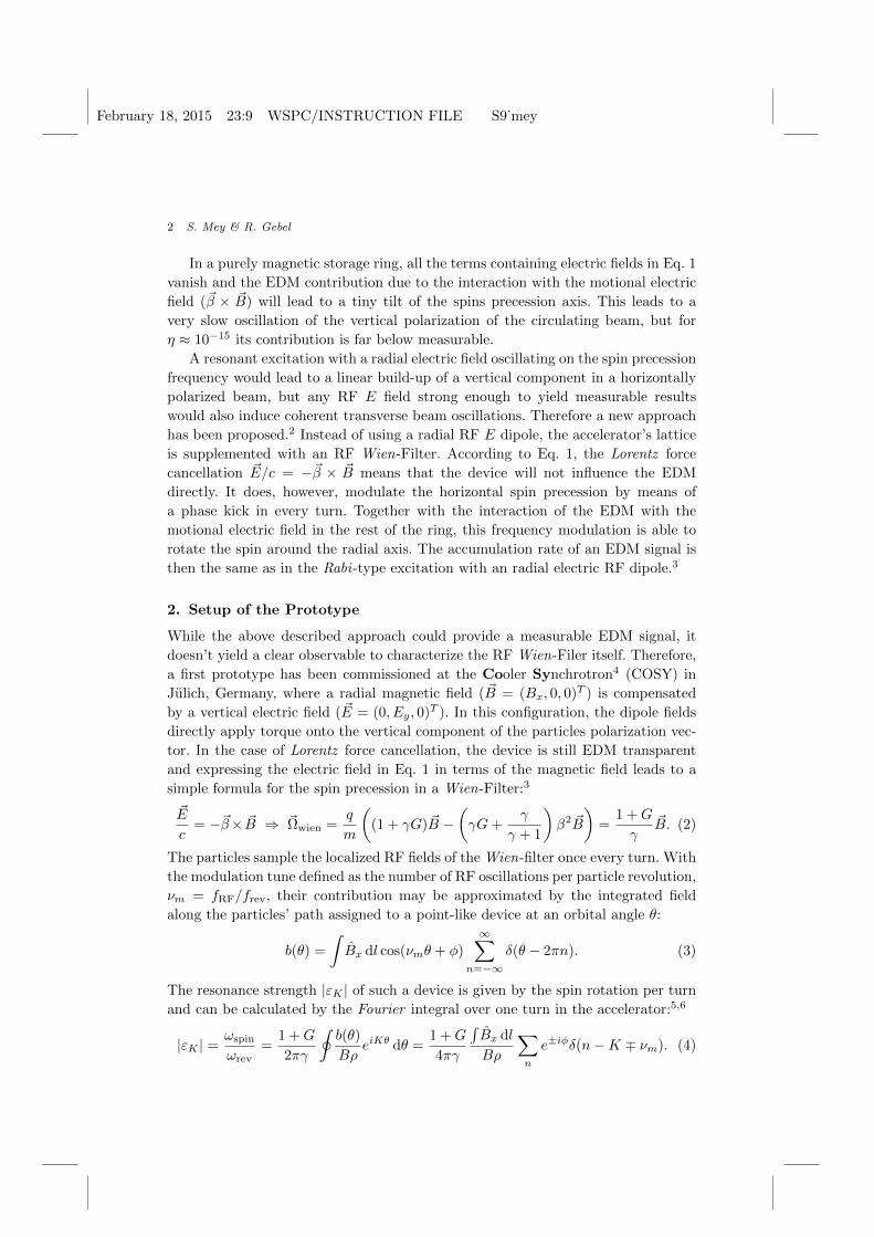
Fig. 1. An explosion drawing showing the main components of the RF E ×B dipole.
An artificial spin resonance occurs at all side-bands with a frequency corresponding
to the spin tune:
K!= γG = n± νm ⇔ fRF = frev|n− γG|; n ∈ Z. (5)
In the scope of the current JEDI experiments, deuterons with a momentum of
970 MeV/c are stored at COSY. In this case, γ = 1.126 and the resulting spin tune
is γG = −0.1609. The resulting fundamental mode is located at fRF = 121 kHz
with n = ±1 harmonics at 629 kHz and 871 kHz.
The magnetic RF dipole has been realized in the form of coil wound lengthwise
around a ceramic part of the beam-pipe. Water cooling provides stable operating
conditions and low-loss, RF capable ferrite blocks improve the homogeneity in the
transverse plane. It is driven by means of a parallel resonance circuit with a quality
factor of Q ≈ 20. A similar but separate resonance circuit drives the electric RF
dipole. The electric field is generated by the potential difference between two stain-
less steel electrodes inside the vacuum chamber spanned over glass rods held by a
frame inside the flanges of the ceramic beam-chamber. For details see Fig.1.
Without any additional control loops and further dedicated cooling systems it
is possible to run the system up to 90 W input power in continuous, long term
operation. The maximum current amplitude in the coil is then 5 A leading to an in-
tegrated field strength if∫Bx dz = 0.175 T mm. The corresponding integral electric
field between the electrodes is∫Ey dz = 24.1 kV.
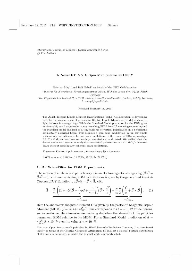
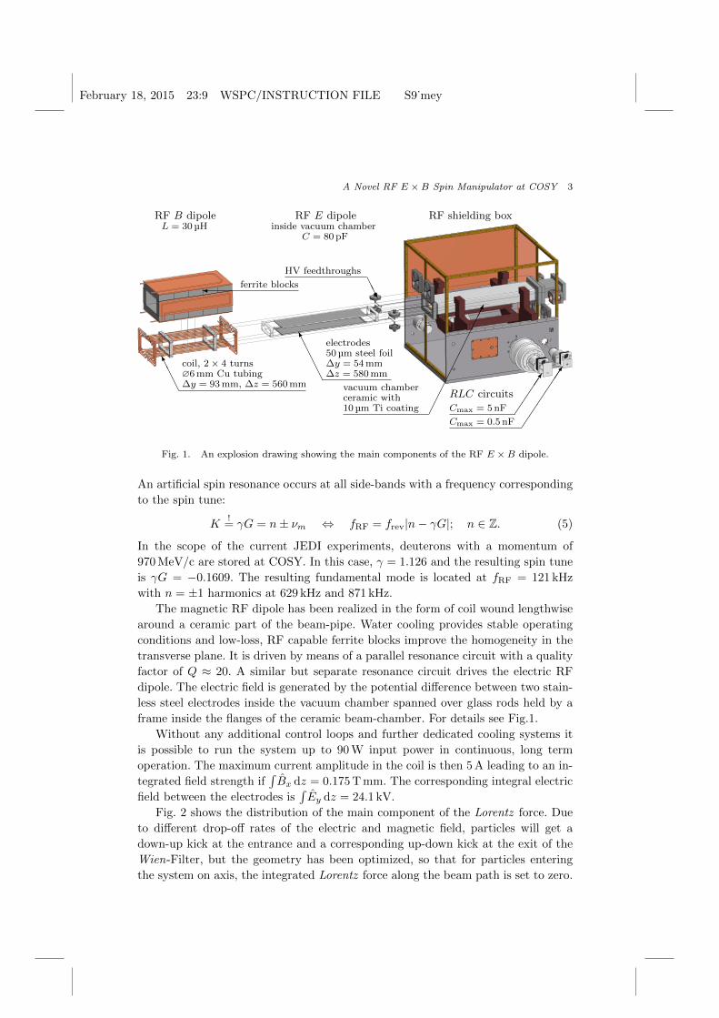
Fig. 2 shows the distribution of the main component of the Lorentz force. Due
to different drop-off rates of the electric and magnetic field, particles will get a
down-up kick at the entrance and a corresponding up-down kick at the exit of the
Wien-Filter, but the geometry has been optimized, so that for particles entering
the system on axis, the integrated Lorentz force along the beam path is set to zero.
February 18, 2015 23:9 WSPC/INSTRUCTION FILE S9˙mey
4 S. Mey & R. Gebel
x / m
-0.05
0
0.05
z / m-1 -0.5 0 0.5 1
Fy
/ eV
/m
-200
-100
0
100
200
310×
Fy
/ eV
/m
-200
-100
0
100
200310×
Fy
/ eV
/m
-200
-100
0
100
200310×
eEy
ecβBx
x / m
-0.05
0
0.05
z / m-1 -0.5 0 0.5 1
Fy
/ eV
/m
-200
-100
0
100
200
310×
Fy
/ eV
/m
-200
-100
0
100
200310×
Fy
/ eV
/m
-200
-100
0
100
200310×
6Fy = e (Ey + cβBx)
Fig. 2. Simulation of the Lorentz force plotted across a horizontal cut through the center of the
beam pipe (y = 0). The results have been normalized to a coil current amplitude of I = 1A.
3. Measurements
To achieve Lorentz force cancellation, the phase as well as the amplitudes of the
E and B fields have to be adjusted. The optics of the accelerator was modified so
that a vertical betatron sideband was located exactly on top of the frequency of the
RF E × B dipole at 871.52 kHz to achieve maximum sensitivity to induced beam
oscillations. Next, the acceptance was limited by installing a massive carbon block
directly above the beam as target for the polarimeter. The beam current monitor of
COSY could thus be used as a precise tool for the matching of the RF Wien-Filter.
With a well cooled beam, a sensitivity to amplitude and phase changes in the per
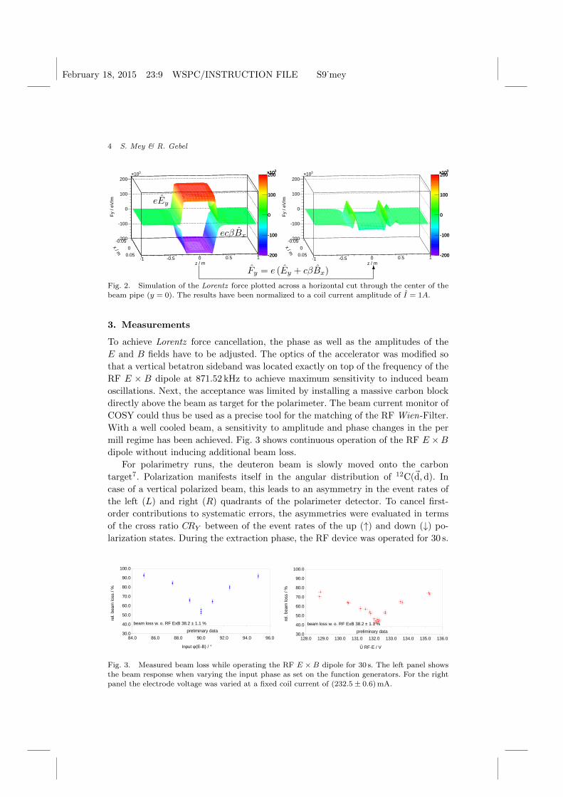
mill regime has been achieved. Fig. 3 shows continuous operation of the RF E ×Bdipole without inducing additional beam loss.
For polarimetry runs, the deuteron beam is slowly moved onto the carbon
target7. Polarization manifests itself in the angular distribution of 12C(~d,d). In
case of a vertical polarized beam, this leads to an asymmetry in the event rates of
the left (L) and right (R) quadrants of the polarimeter detector. To cancel first-
order contributions to systematic errors, the asymmetries were evaluated in terms
of the cross ratio CRY between of the event rates of the up (↑) and down (↓) po-
larization states. During the extraction phase, the RF device was operated for 30 s.
84.0 86.0 88.0 90.0 92.0 94.0 96.030.0
40.0
50.0
60.0
70.0
80.0
90.0
100.0
Phase Scan @ 30% Output Amplitude, Natural Beamloss (38.2±1.1)%
fQy = 871.52 kHz, f = 871.4282 kHz, Î RF-B = (232.6±0.6) mA, Û RF-E = (132.0±0.3) V
Input φ(E-B) / °
rel.
beam
loss
/ %
beam loss w. o. RF ExB 38.2 ± 1.1 %
preliminary data
128.0 129.0 130.0 131.0 132.0 133.0 134.0 135.0 136.030.0
40.0
50.0
60.0
70.0
80.0
90.0
100.0
Amplitude Scan @ 30% Output Amplitude, Natural Beamloss (38.2±1.1)%
fQy = 871.52 kHz, f = 871.4282 kHz, Î RF-B = (232.5±0.6) V, Input φ(E-B) = 90°
Û RF-E / V
rel.
beam
loss
/ %
beam loss w. o. RF ExB 38.2 ± 1.1 %
preliminary data
Fig. 3. Measured beam loss while operating the RF E × B dipole for 30 s. The left panel shows
the beam response when varying the input phase as set on the function generators. For the rightpanel the electrode voltage was varied at a fixed coil current of (232.5± 0.6) mA.
February 18, 2015 23:9 WSPC/INSTRUCTION FILE S9˙mey
A Novel RF E ×B Spin Manipulator at COSY 5
/ ndf 2χ 121.9 / 95
cos Offset 0.00196± 0.02555
cos Phase 4.50± -73.03
cos Freq / Hz 0.0030± 0.2011
exp scale 0.0086± 0.1483
/ s τexp 0.43± 4.68
t / s90 95 100 105 110 115
y C
R
-0.3
-0.2
-0.1
0
0.1
0.2
0.3
/ ndf 2χ 121.9 / 95
cos Offset 0.00196± 0.02555
cos Phase 4.50± -73.03
cos Freq / Hz 0.0030± 0.2011
exp scale 0.0086± 0.1483
/ s τexp 0.43± 4.68
: 4.6804 sτRun3585 | fPy: 0.2011 Hz,
/ kHzrev
)fγ=(1-GRFf871.4276 871.4278 871.428
fPy
/ Hz
0.2
0.25
0.3
0.35
0.4 / ndf 2χ 4.811 / 3
Curvature 9.91e+04± 1.73e+06
Minimum at 5.632e-06± 871.4
Offset 0.002057± 0.2012
/ ndf 2χ 4.811 / 3
Curvature 9.91e+04± 1.73e+06
Minimum at 5.632e-06± 871.4
Offset 0.002057± 0.2012
3574
3575
3576
3577
3584
3585
= 871.427713 kHzRF = 0.2012 Hz at fmin
fPy
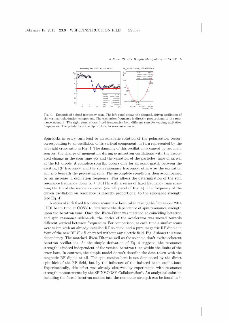
Fig. 4. Example of a fixed frequency scan. The left panel shows the damped, driven oscillation ofthe vertical polarization component. The oscillation frequency is directly proportional to the reso-
nance strength. The right panel shows fitted frequencies from different runs for varying excitation
frequencies. The points form the tip of the spin resonance curve.
Spin-kicks in every turn lead to an adiabatic rotation of the polarization vector,
corresponding to an oscillation of its vertical component, in turn represented by the
left-right cross-ratio in Fig. 4. The damping of this oscillation is caused by two main
sources: the change of momentum during synchrotron oscillations with the associ-
ated change in the spin tune γG and the variation of the particles’ time of arrival
at the RF dipole. A complete spin flip occurs only for an exact match between the
exciting RF frequency and the spin resonance frequency, otherwise the excitation
will slip beneath the precessing spin. The incomplete spin-flip is then accompanied
by an increase in oscillation frequency. This allows the determination of the spin
resonance frequency down to ≈ 0.01 Hz with a series of fixed frequency runs scan-
ning the tip of the resonance curve (see left panel of Fig. 4). The frequency of the
driven oscillation on resonance is directly proportional to the resonance strength
(see Eq. 4).
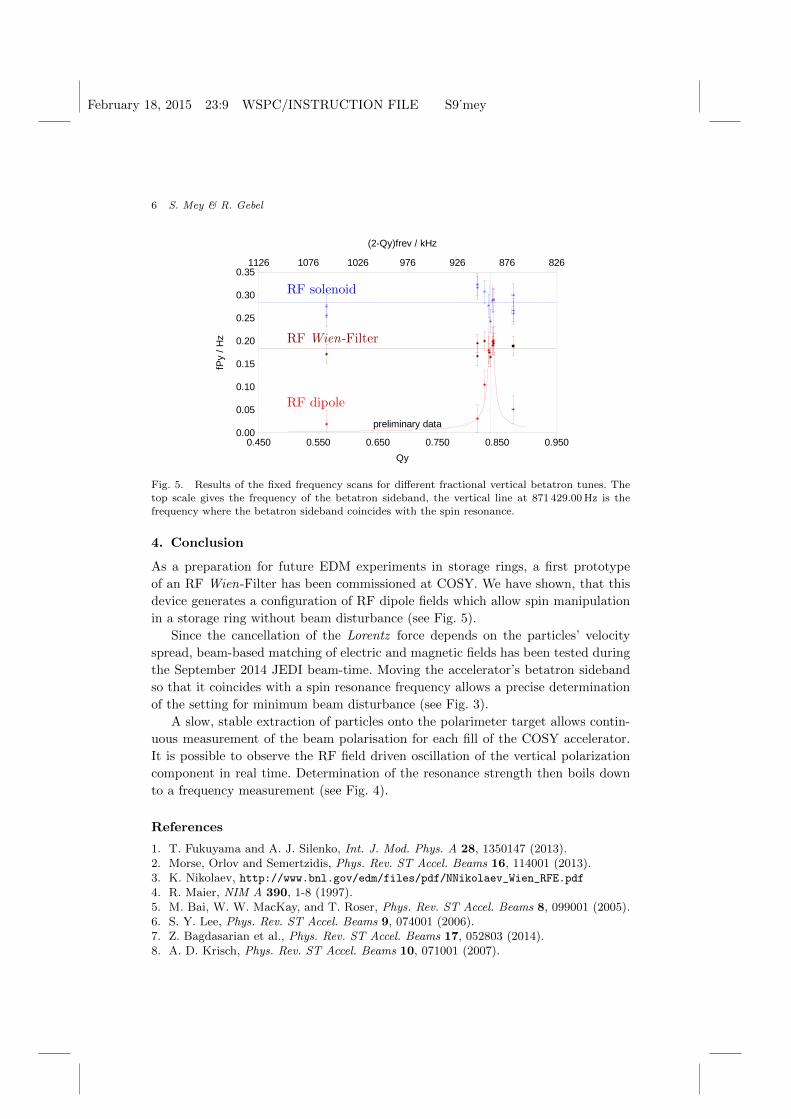
A series of such fixed frequency scans have been taken during the September 2014
JEDI beam time at COSY to determine the dependence of spin resonance strength
upon the betatron tune. Once the Wien-Filter was matched at coinciding betatron
and spin resonance sidebands, the optics of the accelerator was moved towards
different vertical betatron frequencies. For comparison, at each tune a similar scans
were taken with an already installed RF solenoid and a pure magnetic RF dipole in
form of the new RF E×B operated without any electric field. Fig. 5 shows this tune
dependency. The matched Wien-Filter as well as the solenoid don’t excite coherent
betatron oscillations. As the simple derivation of Eq. 4 suggests, the resonance
strength is indeed independent of the vertical betatron tune within the limits of the
error bars. In contrast, the simple model doesn’t describe the data taken with the
magnetic RF dipole at all. The spin motion here is not dominated by the direct
spin kick of the RF field, but by the influence of the induced beam oscillations.
Experimentally, this effect was already observed by experiments with resonance
strength measurements by the SPIN@COSY Collaboration8. An analytical solution
including the forced betatron motion into the resonance strength can be found in 6.
February 18, 2015 23:9 WSPC/INSTRUCTION FILE S9˙mey
6 S. Mey & R. Gebel
0.450 0.550 0.650 0.750 0.850 0.950
826876926976102610761126
0.00
0.05
0.10
0.15
0.20
0.25
0.30
0.35
Qy
fPy
/ H
z
(2-Qy)frev / kHz
preliminary data
RF solenoid
RF Wien-Filter
RF dipole
Fig. 5. Results of the fixed frequency scans for different fractional vertical betatron tunes. The
top scale gives the frequency of the betatron sideband, the vertical line at 871 429.00 Hz is thefrequency where the betatron sideband coincides with the spin resonance.
4. Conclusion
As a preparation for future EDM experiments in storage rings, a first prototype
of an RF Wien-Filter has been commissioned at COSY. We have shown, that this
device generates a configuration of RF dipole fields which allow spin manipulation
in a storage ring without beam disturbance (see Fig. 5).
Since the cancellation of the Lorentz force depends on the particles’ velocity
spread, beam-based matching of electric and magnetic fields has been tested during
the September 2014 JEDI beam-time. Moving the accelerator’s betatron sideband
so that it coincides with a spin resonance frequency allows a precise determination
of the setting for minimum beam disturbance (see Fig. 3).
A slow, stable extraction of particles onto the polarimeter target allows contin-
uous measurement of the beam polarisation for each fill of the COSY accelerator.
It is possible to observe the RF field driven oscillation of the vertical polarization
component in real time. Determination of the resonance strength then boils down
to a frequency measurement (see Fig. 4).
References
1. T. Fukuyama and A. J. Silenko, Int. J. Mod. Phys. A 28, 1350147 (2013).2. Morse, Orlov and Semertzidis, Phys. Rev. ST Accel. Beams 16, 114001 (2013).3. K. Nikolaev, http://www.bnl.gov/edm/files/pdf/NNikolaev_Wien_RFE.pdf4. R. Maier, NIM A 390, 1-8 (1997).5. M. Bai, W. W. MacKay, and T. Roser, Phys. Rev. ST Accel. Beams 8, 099001 (2005).6. S. Y. Lee, Phys. Rev. ST Accel. Beams 9, 074001 (2006).7. Z. Bagdasarian et al., Phys. Rev. ST Accel. Beams 17, 052803 (2014).8. A. D. Krisch, Phys. Rev. ST Accel. Beams 10, 071001 (2007).