Embed Size (px)
Citation preview
A novel non-isolated active charge balancing
architecture for lithium-ion batteries
Manuel Räber IEEE Student
Dominic Hink, Andreas Heinzelmann
Institute for Energy Systems and Fluid Engineering
Zurich University of Applied Sciences
8400 Winterthur, CH
Djaffar Ould Abdeslam IEEE Senior
IUT de Mulhouse, MIPS Laboratory
Université de Haute Alsace
68093 Mulhouse Cedex, F
Abstract — Active charge balancing is an approved technique
to implement high performance lithium-ion battery systems.
Enhanced balancing speeds and reduced balancing losses are
feasible compared to passive balancing. The new architecture
proposed in this paper overcomes several drawbacks of other
active balancing methods. It consists of only 2 non-isolated DC/DC
converters. In combination with a MOSFET switch matrix it is
able to balance arbitrary cells of a battery system at high currents.
Adjacent cells can be balanced simultaneously. For the given
setting, numerical simulations show an overall balancing
efficiency of approx. 92.5%, compared to 89.4% for a stack-to-
cell-to-stack method (St2C2St, bidirectional fly-back) at similar
balancing times. The usable capacity increases from 97.1% in a
passively balanced system to 99.5% for the new method.
Keywords — Battery management system, Active charge
balancing, Lithium-ion battery systems, Active balancing techniques
I. INTRODUCTION
Large lithium ion batteries consist of many single cells that
are connected in series and in parallel to deliver the desired
system voltage and energy capacity. The electric parameters of
individual cells vary due to fabrication tolerances, ageing and
temperature gradients inside the pack. Therefore, the usable
capacity of a battery system is limited by its weakest cell or cell
level and the remaining energy in the other cells stays
untouched. Weaker cells reach charge and discharge limits
earlier. The deviations increase with increased use of the battery
[1]. Since the beginning of the use of lithium-ion technology,
balancing circuits ensure to keep the charging process as safe
as possible. Active balancing solutions are able to transfer
charge between individual cells at high efficiency. They
represent a promising possibility to enhance the energy
efficiency and eco friendliness of lithium-ion battery systems
when applied both during the charging and discharging process,
as shown in Fig. 1. The left side illustrates the charging process.
During passive balancing, the excess charge is dissipated and
lost. On the contrary, during active balancing, the excess charge
is transferred to other cells in the system. When implementing
active balancing, the discharge time can be increased as shown
on the right side of Fig. 1. Charge which would stay unused in
the cell is transferred to another, weaker cell. This leads to an
increase of the usable capacity of the battery.
A large number of methods and circuits was discussed in the
literature in recent years. The superiority over passive balancing
in terms of energy efficiency and speed has been proven in
theory ([2], [3], [4]) and by measurement (see references in
Table 1 and [5], [6], [7]). Despite the advantages, battery
systems with active balancing are still rare in industrial
applications. The reasons are manifold and range from higher
component costs to reduced reliability and larger dimensions.
Commonly, four basic topologies are distinguished: Cell-to-
cell, cell-to-stack, stack-to-cell and stack-to-cell-to-stack,
which is a combination of the previous two.
FIG. 1. BASIC FUNCTION PRINCIPLE OF ACTIVE CHARGE BALANCING
Apart from these standard topologies other circuits and types
have been proposed in [8], [7] and [9]. For a general topology
overview see [10] and [11].
This paper is the first to propose the use of two non-isolated
DC/DC-converters and a switch matrix as a new approach to
active charge balancing in lithium-ion battery systems. On the
following pages the functionality and the estimated
performance of the method is presented. Section II summarizes
the state of art and available publications on non-isolated
balancing methods. In section III, the new method is described
in detail. The simulation settings and the balancing algorithm
as well as the simulation results are given in section IV. Section
V compares the proposed method to existing ones in terms of
complexity and balancing performance.
II. STATE OF THE ART
As shown in [12], active balancing can increase the usable
capacity of a battery system during the discharging process by
1% to 6%, depending on the cell and system parameters. In a
comparison presented in [2] the cell-to-cell topology shows
superior performance compared to any other active balancing
methods in terms of balancing speed and efficiency. However,
cell-to-cell balancers are technically challenging due to the
numerous power paths. Two hardware realization options are
available: Either with isolated power converters or with a non-
isolated converter interfacing a floating capacitor tank.
Non-isolated methods for charge balancing reach high
efficiencies at a small size. The most promising techniques
proposed in literature are mentioned in Table 1. If available, the
tested balancing current and the measured efficiency of the
hardware are given as well.
TABLE 1: OVERVIEW OF NON-ISOLATED ACTIVE BALANCING METHODS
Architecture Max. balancing
current
Max. balancing
efficiency
Single switched capacitor
[13]
2 A 83 %
Single switched capacitor
[14]
1 A > 90 %
Switched inductors [15] 1 A -
Switched inductors [16] 5 A 85 %
Series bidirectional
converters [17]
- -
PWM converters [10] - -
Switched capacitors [18] - -
Step-up converter [19] - - For an efficiency overview of other active balancing methods see [14]
III. DESCRIPTION OF THE NEW METHOD
The new active balancing method is called Buck-In/Boost-
Out. In accordance with the used nomenclature, the description
is stack-to-cells-to-stack. The balancing principle is based on
the selective charging and discharging of a variable number of
battery cells connected in series. A buck converter works as a
charging unit, which transfers charge from the stack to the
selected cells. Discharge is performed in the similar way via a
boost converter.
The topology has a switch matrix to connect the desired cells
with the converters. The corresponding switches must be
blocking in both directions and can be realized with 2
MOSFETs each (see Fig. 2). The output voltage range of the
buck converter and the input voltage range of the boost
converter must be wide enough to cover the voltage range of 1
to n-1 cells. In this way, all cells can be actively charged and
discharged up to the highest level in the stack. Simultaneous
balancing of multiple cells is only possible for adjacent cells.
For the uppermost cell, balancing takes place by accessing all
cells below it.
FIG. 2. AC SWITCH AND N-MOSFET EQUIVALENT CIRCUIT
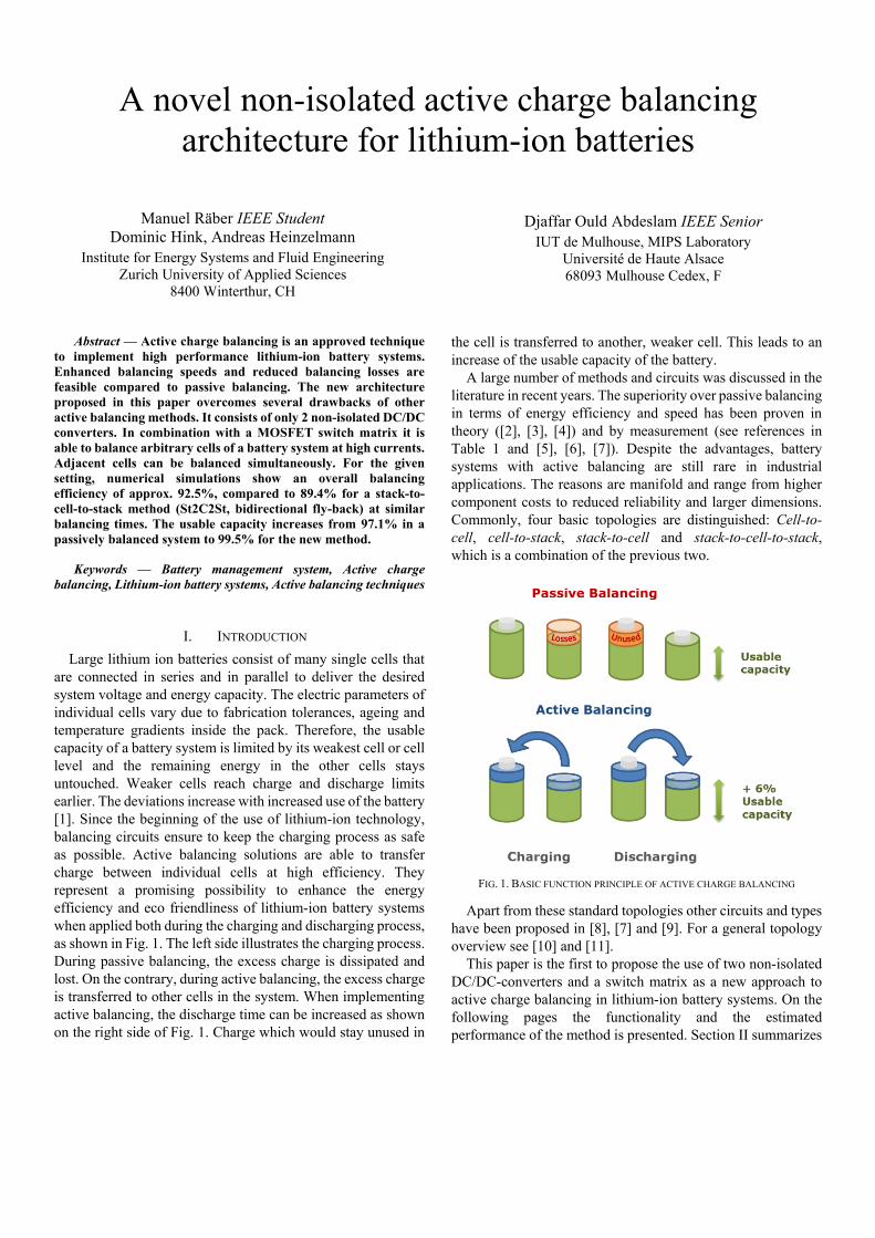
Fig. 3 shows the discussed balancing method for a battery
system with n cells in series. The operating parts are dyed to
indicate the working principle. The buck converter delivers
energy from the stack through the switch Sw_A2 to Cell 1 and
Cell 2. These are charged with the converter output current IBuck.
Simultaneously, the boost converter discharges Cell 1 through
Sw_B1 with the converter input current IBoost. Given that IBuck =
IBoost, the sum of the current of Cell 1 is 0 A and Cell 2 is charged
with IBuck (positive balancing). Generally, cells are charged by
connecting the buck converter on a higher position than the
boost converter. Discharging is carried out in reverse order.
FIG. 3. BUCK-IN/BOOST-OUT ACTIVE BALANCING
The resulting stack current is the sum of the buck input
current and the boost output current. It is a function of the
converter efficiencies (𝜂Buck and 𝜂Boost), the average cell voltage UCell the number of cells n and the state of the switch
matrix (Buck output position: x, Boost input position: y):
𝐼𝑆𝑡𝑎𝑐𝑘− =𝐼𝐵𝑢𝑐𝑘 ∙ 𝑥 ∙ 𝑈𝐶𝑒𝑙𝑙
𝜂𝐵𝑢𝑐𝑘 ∙ 𝑈𝑆𝑡𝑎𝑐𝑘 .
(1)
𝐼𝑆𝑡𝑎𝑐𝑘+ =𝐼𝐵𝑜𝑜𝑠𝑡 ∙ 𝑦 ∙ 𝑈𝐶𝑒𝑙𝑙 ∙ 𝜂𝐵𝑜𝑜𝑠𝑡
𝑈𝑆𝑡𝑎𝑐𝑘 . (2)
Assuming UStack = nUCell and IBuck = IBoost = IBal, it follows that
𝐼𝑆𝑡𝑎𝑐𝑘 = 𝐼𝑆𝑡𝑎𝑐𝑘+−𝐼𝑆𝑡𝑎𝑐𝑘− = 𝐼𝐵𝑎𝑙(𝑦 ∙ 𝜂𝐵𝑜𝑜𝑠𝑡 −
𝑥𝜂𝐵𝑢𝑐𝑘
)
𝑛. (3)
Table 2 shows different possible balancing states of the
circuit. In the first row, the cell numbers are listed that are
selected for balancing. The second row states whether the cell
is charged or discharged. Row 3 and 4 indicate if both
converters are necessary for balancing and row 5 gives the
correct setting of the switch matrix.
TABLE 2: BALANCING MODES
Desired cell
for balancing
Balancing
direction
Buck
converter
Boost
converter
Active
switch
#2 Charge IBal IBal A2, B1
#3 & #4 Charge IBal IBal A4, B2
#1 Charge IBal - A1
#n Discharge IBal - A(n-1)
#1 & #2 Discharge - IBal B2
#2 Discharge IBal IBal A2, B3
The converter power and total losses depend on the number
of cells in the stack n and the position of the balanced cell inside
the stack. They increase with increasing number of cells and
higher position. �⃗�𝐵𝑢𝑐𝑘 and �⃗�𝐵𝑜𝑜𝑠𝑡 are the corresponding efficiency vectors. For any cell, except the topmost one, the
overall balancing efficiency for charging at the cell position j
(positive balancing) is
𝜂𝐵𝑎𝑙𝐶𝑗 = 1 − 𝑗 ∙1−𝜂𝐵𝑢𝑐𝑘𝑗
𝜂𝐵𝑢𝑐𝑘𝑗
− (𝑗 − 1) ∙ (1 − 𝜂𝐵𝑜𝑜𝑠𝑡𝑗−1) . (4)
For discharging (negative balancing) of cells 1 to j-1, the
efficiency calculates as follows:
𝜂𝐵𝑎𝑙𝐷𝑗= 1 − (𝑗 − 1) ∙
1−𝜂𝐵𝑢𝑐𝑘𝑗−1
𝜂𝐵𝑢𝑐𝑘𝑗−1
− 𝑗 ∙ (1 − 𝜂𝐵𝑜𝑜𝑠𝑡𝑗). (5)
For the topmost cell n, only one converter is required to
perform the balancing. The efficiencies for charging and
discharging are calculated as:
𝜂𝐵𝑎𝑙𝐶𝑛= 1 − (𝑛 − 1) ∙ (1 − 𝜂𝐵𝑜𝑜𝑠𝑡𝑛−1
), (6)
𝜂𝐵𝑎𝑙𝐷𝑛= 1 − (𝑛 − 1) ∙
1 − 𝜂𝐵𝑢𝑐𝑘𝑛−1
𝜂𝐵𝑢𝑐𝑘𝑛−1
. (7)
Equations (4)-(7) are valid only for the balancing of one cell,
not of a group of adjascent cells.
IV. SIMULATION AND PERFORMANCE EVALUATION
A. Simulation settings
The numeric simulations were done in MATLAB. The cell
capacity values are random numbers as a function of the chosen
cell parameters (see Table 3). A MATLAB script processes
these values according to the balancing algorithm shown in Fig.
4. The battery parameter used in the simulation are given in
Table 3.
TABLE 3: SIMULATION CELL PARAMETERS
Cell parameter Value
Nominal capacity Cnom 100 Ah
Nominal voltage Unom 3.7 V
Standard deviation σ0 2…3 %
Number of cells n 8
Balancing current Ibal 10 A
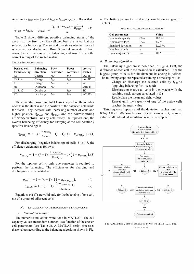
B. Balancing algorithm
The balancing algorithm is described in Fig. 4. First, the
difference of each cell to the mean value is calculated. Then the
biggest group of cells for simultaneous balancing is defined.
The following steps are repeated assuming a time step of 1 s:
- Charge or discharge the selected cells by 𝐼𝐵𝑎𝑙 𝐴𝑠
(applying balancing for 1 second)
- Discharge or charge all cells in the system with the
resulting stack current calculated in (3)
- Recalculate the mean and delta values
- Repeat until the capacity of one of the active cells
reaches the mean value
This sequence repeats until the deviation reaches less than
0.2σ0. After 10’000 simulations of each parameter set, the mean
value of all individual simulation results is computed.
FIG. 4. ALGORITHM FOR THE CELLS-TO-STACK-TO-CELLS BALANCING
SIMULATION
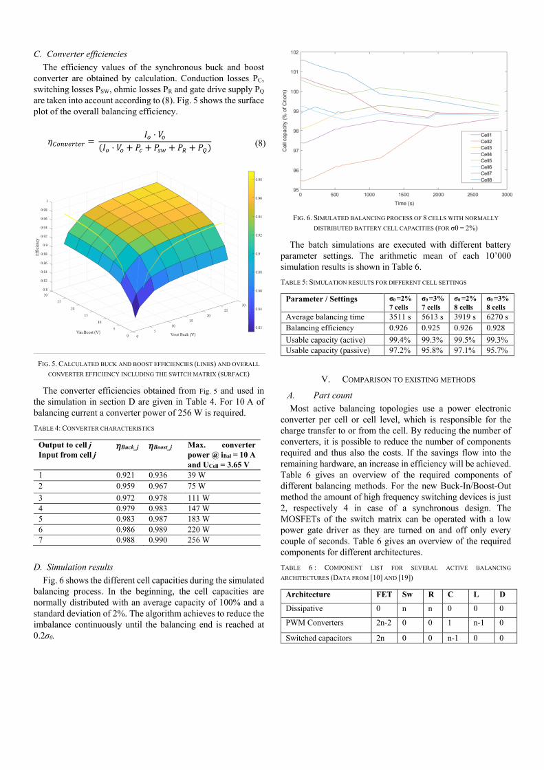
C. Converter efficiencies
The efficiency values of the synchronous buck and boost
converter are obtained by calculation. Conduction losses PC,
switching losses PSW, ohmic losses PR and gate drive supply PQ
are taken into account according to (8). Fig. 5 shows the surface
plot of the overall balancing efficiency.
𝜂𝐶𝑜𝑛𝑣𝑒𝑟𝑡𝑒𝑟 = 𝐼𝑜 ⋅ 𝑉𝑜
(𝐼𝑜 ⋅ 𝑉𝑜 + 𝑃𝑐 + 𝑃𝑠𝑤 + 𝑃𝑅 + 𝑃𝑄)
(8)
(3)
FIG. 5. CALCULATED BUCK AND BOOST EFFICIENCIES (LINES) AND OVERALL
CONVERTER EFFICIENCY INCLUDING THE SWITCH MATRIX (SURFACE)
The converter efficiencies obtained from Fig. 5 and used in
the simulation in section D are given in Table 4. For 10 A of
balancing current a converter power of 256 W is required.
TABLE 4: CONVERTER CHARACTERISTICS
Output to cell j
Input from cell j 𝜂Buck_j 𝜂Boost_j Max. converter
power @ iBal = 10 A
and UCell = 3.65 V
1 0.921 0.936 39 W
2 0.959 0.967 75 W
3 0.972 0.978 111 W
4 0.979 0.983 147 W
5 0.983 0.987 183 W
6 0.986 0.989 220 W
7 0.988 0.990 256 W
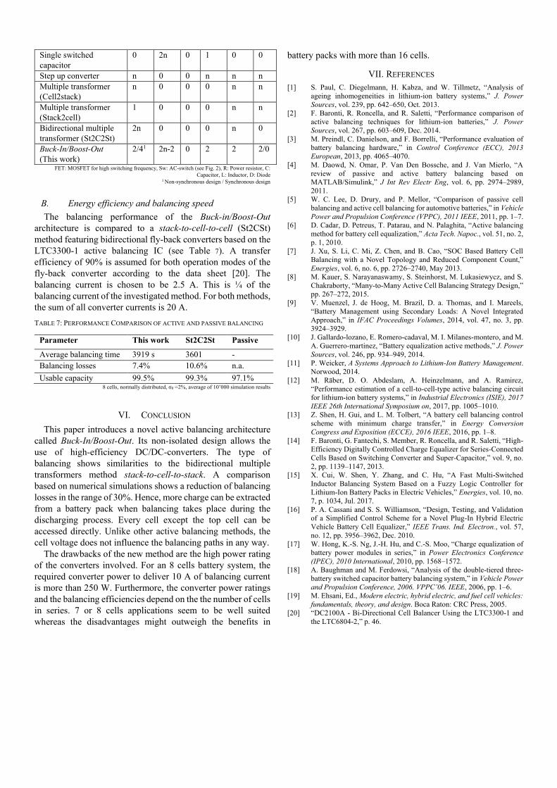
D. Simulation results
Fig. 6 shows the different cell capacities during the simulated
balancing process. In the beginning, the cell capacities are
normally distributed with an average capacity of 100% and a
standard deviation of 2%. The algorithm achieves to reduce the
imbalance continuously until the balancing end is reached at
0.2σ0.
FIG. 6. SIMULATED BALANCING PROCESS OF 8 CELLS WITH NORMALLY
DISTRIBUTED BATTERY CELL CAPACITIES (FOR σ0 = 2%)
The batch simulations are executed with different battery
parameter settings. The arithmetic mean of each 10’000
simulation results is shown in Table 6.
TABLE 5: SIMULATION RESULTS FOR DIFFERENT CELL SETTINGS
Parameter / Settings σ0 =2%
7 cells σ0 =3%
7 cells σ0 =2%
8 cells σ0 =3%
8 cells
Average balancing time 3511 s 5613 s 3919 s 6270 s
Balancing efficiency 0.926 0.925 0.926 0.928
Usable capacity (active) 99.4% 99.3% 99.5% 99.3%
Usable capacity (passive) 97.2% 95.8% 97.1% 95.7%
V. COMPARISON TO EXISTING METHODS
A. Part count
Most active balancing topologies use a power electronic
converter per cell or cell level, which is responsible for the
charge transfer to or from the cell. By reducing the number of
converters, it is possible to reduce the number of components
required and thus also the costs. If the savings flow into the
remaining hardware, an increase in efficiency will be achieved.
Table 6 gives an overview of the required components of
different balancing methods. For the new Buck-In/Boost-Out
method the amount of high frequency switching devices is just
2, respectively 4 in case of a synchronous design. The
MOSFETs of the switch matrix can be operated with a low
power gate driver as they are turned on and off only every
couple of seconds. Table 6 gives an overview of the required
components for different architectures.
TABLE 6 : COMPONENT LIST FOR SEVERAL ACTIVE BALANCING
ARCHITECTURES (DATA FROM [10] AND [19])
Architecture FET Sw R C L D
Dissipative 0 n n 0 0 0
PWM Converters 2n-2 0 0 1 n-1 0
Switched capacitors 2n 0 0 n-1 0 0
Single switched
capacitor
0 2n 0 1 0 0
Step up converter n 0 0 n n n
Multiple transformer
(Cell2stack)
n 0 0 0 n n
Multiple transformer
(Stack2cell)
1 0 0 0 n n
Bidirectional multiple
transformer (St2C2St)
2n 0 0 0 n 0
Buck-In/Boost-Out
(This work)
2/41 2n-2 0 2 2 2/0
FET: MOSFET for high switching frequency, Sw: AC-switch (see Fig. 2), R: Power resistor, C:
Capacitor, L: Inductor, D: Diode 1 Non-synchronous design / Synchronous design
B. Energy efficiency and balancing speed
The balancing performance of the Buck-in/Boost-Out
architecture is compared to a stack-to-cell-to-cell (St2CSt)
method featuring bidirectional fly-back converters based on the
LTC3300-1 active balancing IC (see Table 7). A transfer
efficiency of 90% is assumed for both operation modes of the
fly-back converter according to the data sheet [20]. The
balancing current is chosen to be 2.5 A. This is ¼ of the
balancing current of the investigated method. For both methods,
the sum of all converter currents is 20 A.
TABLE 7: PERFORMANCE COMPARISON OF ACTIVE AND PASSIVE BALANCING
Parameter This work St2C2St Passive
Average balancing time 3919 s 3601 -
Balancing losses 7.4% 10.6% n.a.
Usable capacity 99.5% 99.3% 97.1% 8 cells, normally distributed, σ0 =2%, average of 10’000 simulation results
VI. CONCLUSION
This paper introduces a novel active balancing architecture
called Buck-In/Boost-Out. Its non-isolated design allows the
use of high-efficiency DC/DC-converters. The type of
balancing shows similarities to the bidirectional multiple
transformers method stack-to-cell-to-stack. A comparison
based on numerical simulations shows a reduction of balancing
losses in the range of 30%. Hence, more charge can be extracted
from a battery pack when balancing takes place during the
discharging process. Every cell except the top cell can be
accessed directly. Unlike other active balancing methods, the
cell voltage does not influence the balancing paths in any way.
The drawbacks of the new method are the high power rating
of the converters involved. For an 8 cells battery system, the
required converter power to deliver 10 A of balancing current
is more than 250 W. Furthermore, the converter power ratings
and the balancing efficiencies depend on the the number of cells
in series. 7 or 8 cells applications seem to be well suited
whereas the disadvantages might outweigh the benefits in
battery packs with more than 16 cells.
VII. REFERENCES
[1] S. Paul, C. Diegelmann, H. Kabza, and W. Tillmetz, “Analysis of
ageing inhomogeneities in lithium-ion battery systems,” J. Power
Sources, vol. 239, pp. 642–650, Oct. 2013.
[2] F. Baronti, R. Roncella, and R. Saletti, “Performance comparison of
active balancing techniques for lithium-ion batteries,” J. Power
Sources, vol. 267, pp. 603–609, Dec. 2014.
[3] M. Preindl, C. Danielson, and F. Borrelli, “Performance evaluation of
battery balancing hardware,” in Control Conference (ECC), 2013
European, 2013, pp. 4065–4070.
[4] M. Daowd, N. Omar, P. Van Den Bossche, and J. Van Mierlo, “A
review of passive and active battery balancing based on
MATLAB/Simulink,” J Int Rev Electr Eng, vol. 6, pp. 2974–2989,
2011.
[5] W. C. Lee, D. Drury, and P. Mellor, “Comparison of passive cell
balancing and active cell balancing for automotive batteries,” in Vehicle
Power and Propulsion Conference (VPPC), 2011 IEEE, 2011, pp. 1–7.
[6] D. Cadar, D. Petreus, T. Patarau, and N. Palaghita, “Active balancing
method for battery cell equalization,” Acta Tech. Napoc., vol. 51, no. 2,
p. 1, 2010.
[7] J. Xu, S. Li, C. Mi, Z. Chen, and B. Cao, “SOC Based Battery Cell
Balancing with a Novel Topology and Reduced Component Count,”
Energies, vol. 6, no. 6, pp. 2726–2740, May 2013.
[8] M. Kauer, S. Narayanaswamy, S. Steinhorst, M. Lukasiewycz, and S.
Chakraborty, “Many-to-Many Active Cell Balancing Strategy Design,”
pp. 267–272, 2015.
[9] V. Muenzel, J. de Hoog, M. Brazil, D. a. Thomas, and I. Mareels,
“Battery Management using Secondary Loads: A Novel Integrated
Approach,” in IFAC Proceedings Volumes, 2014, vol. 47, no. 3, pp.
3924–3929.
[10] J. Gallardo-lozano, E. Romero-cadaval, M. I. Milanes-montero, and M.
A. Guerrero-martinez, “Battery equalization active methods,” J. Power
Sources, vol. 246, pp. 934–949, 2014.
[11] P. Weicker, A Systems Approach to Lithium-Ion Battery Management.
Norwood, 2014.
[12] M. Räber, D. O. Abdeslam, A. Heinzelmann, and A. Ramirez,
“Performance estimation of a cell-to-cell-type active balancing circuit
for lithium-ion battery systems,” in Industrial Electronics (ISIE), 2017
IEEE 26th International Symposium on, 2017, pp. 1005–1010.
[13] Z. Shen, H. Gui, and L. M. Tolbert, “A battery cell balancing control
scheme with minimum charge transfer,” in Energy Conversion
Congress and Exposition (ECCE), 2016 IEEE, 2016, pp. 1–8.
[14] F. Baronti, G. Fantechi, S. Member, R. Roncella, and R. Saletti, “High-
Efficiency Digitally Controlled Charge Equalizer for Series-Connected
Cells Based on Switching Converter and Super-Capacitor,” vol. 9, no.
2, pp. 1139–1147, 2013.
[15] X. Cui, W. Shen, Y. Zhang, and C. Hu, “A Fast Multi-Switched
Inductor Balancing System Based on a Fuzzy Logic Controller for
Lithium-Ion Battery Packs in Electric Vehicles,” Energies, vol. 10, no.
7, p. 1034, Jul. 2017.
[16] P. A. Cassani and S. S. Williamson, “Design, Testing, and Validation
of a Simplified Control Scheme for a Novel Plug-In Hybrid Electric
Vehicle Battery Cell Equalizer,” IEEE Trans. Ind. Electron., vol. 57,
no. 12, pp. 3956–3962, Dec. 2010.
[17] W. Hong, K.-S. Ng, J.-H. Hu, and C.-S. Moo, “Charge equalization of
battery power modules in series,” in Power Electronics Conference
(IPEC), 2010 International, 2010, pp. 1568–1572.
[18] A. Baughman and M. Ferdowsi, “Analysis of the double-tiered three-
battery switched capacitor battery balancing system,” in Vehicle Power
and Propulsion Conference, 2006. VPPC’06. IEEE, 2006, pp. 1–6.
[19] M. Ehsani, Ed., Modern electric, hybrid electric, and fuel cell vehicles:
fundamentals, theory, and design. Boca Raton: CRC Press, 2005.
[20] “DC2100A - Bi-Directional Cell Balancer Using the LTC3300-1 and
the LTC6804-2,” p. 46.


![Bridgeless Buck-Boost PFC Converter for Multistring LED Driver€¦ · boost converter as a universal PFC converter [6]. In order to address these issues, a buck-boost converter is](https://img.pdfslide.us/doc/110x75/5eaabf2a4ab79d1e774f9005/bridgeless-buck-boost-pfc-converter-for-multistring-led-driver-boost-converter-as.jpg)