Embed Size (px)
Citation preview
402 Asian Journal of Control, Vol. 9, No. 4, pp. 402-410, December 2007
Manuscript received February 9, 2006; revised November 20, 2006; accepted December 26, 2006.
Subrata Banerjee is with the Department of Electrical Engi-neering, National Institute of Technology, Durgapur-713209, India (e-mail: [email protected], [email protected]).
T. K. Sunil Kumar and Jayanta Pal are with the Department of Electrical Engineering, Indian Institute of Technology, Kharagpur, India. Dinkar Prasad is presently working in Emerson Network Power, India.
A NOVEL METHOD OF CONTROLLER DESIGN FOR SIMULTANEOUS STABILIZATION AND PERFORMANCE
IMPROVEMENT OF AN ELECTROMAGNETIC LEVITATION SYSTEM
Subrata Banerjee, T. K. Sunil Kumar, Jayanta Pal, and Dinkar Prasad
ABSTRACT
This paper describes design and implementation of a control philosophy for simultaneous stabilization and performance improvement of an electro-magnetic levitation system. An electromagnetic levitation system is an inher-ently unstable and strongly nonlinear system. To determine the overall closed loop stability for such a system, cascade lead-lag compensation has mostly been reported [1,2]. However, a single lead controller can not satisfy both sta-bility and performance for such unstable systems [3]. Performance enhance-ment to satisfy the conflicting requirements of fast response with almost zero overshoot and zero steady state error has been successfully achieved by using a two loop controller configuration. The lead controller in the inner loop is designed to ensure stability while the outer loop PI controller is designed for performance enhancement. This approach decouples the twin requirements of stabilization (by the inner loop) and performance achievement (by the outer PI loop). The outermost PI controller has been designed using the ‘Approxi-mate Model Matching’ technique [4]. The proposed control strategy has been implemented and the experimentation has been demonstrated successfully. Different experimental results have been included for verification.
KeyWords: Electromagnetic levitation, lead-lag compensation, approxi-mate model matching control, switched-mode DC to DC chopper, model order reduction technique.
I. INTRODUCTION
The suspension of objects with no visible means of support due to magnetic force is termed as magnetic levita-tion or MAGLEV. Based on the basic principle, magnetic levitation may broadly be classified into two types, elec-trodynamic levitation and electromagnetic levitation. The electrodynamic system actuates through repulsive forces.
Most electrodynamic systems utilize superconducting magnets to generate the forces. In an electromagnetic sys-tem, though, the levitation is produced due to the attractive force between electromagnets and ferromagnetic objects.
Modern applications of levitation in equipment such as magnetic bearings and magnetically levitated vehicles have given renewed impetus to research efforts in the di-rection of electromagnetic levitation. Some other applica-tions of electro-magnetic levitation, apart from application in frictionless bearings and MAGLEV vehicles, are in the fields of levitation of models in a wind tunnel, vibration isolation of sensitive machinery, levitation of molten metal in induction furnaces, levitation of metal slabs during manufacture, etc.
An electromagnetic levitation system (EMLS) is in-herently unstable and is a strongly nonlinear system [1]. To stabilize such an unstable EMLS, the cascade lead com-
S. Banerjee et al.: A Novel Method of Controller Design for Simultaneous Stabilization 403
pensation technique [1,2] is mostly reported. In this work, the proposed levitated system has been initially stabilized by the cascade compensation control scheme utilizing inner current and outer position control loop. It is observed that, though the system has been stabilized, it still exhibits a large steady-state error. In fact, a single controller cannot satisfy both stability and performance for such an unstable plant [3]. To enhance the system performance (steady-state as well as transient), another loop must be introduced into the two-loop structure of EMLS (Fig. 1). It may be noted that the final EMLS must satisfy the conflicting stringent requirements of very fast response with very little over-shoot. Such precision control action may not be easily achieved using a single controller designed by a trial and error controller tuning method. In this paper, a controller design method has been used for implementing such preci-sion control actions. The controller design method relies on the concept of ‘Approximate Model Matching’ (AMM) [4] and matches certain frequency domain parameters that have a great influence in shaping the transient and steady state time domain (high and low frequency) characteristics of the overall closed loop system. The designed controller has been implemented, and the experimental results have been included.
II. DESCRIPTION OF THE PROPOSED LEVITATION SYSTEM
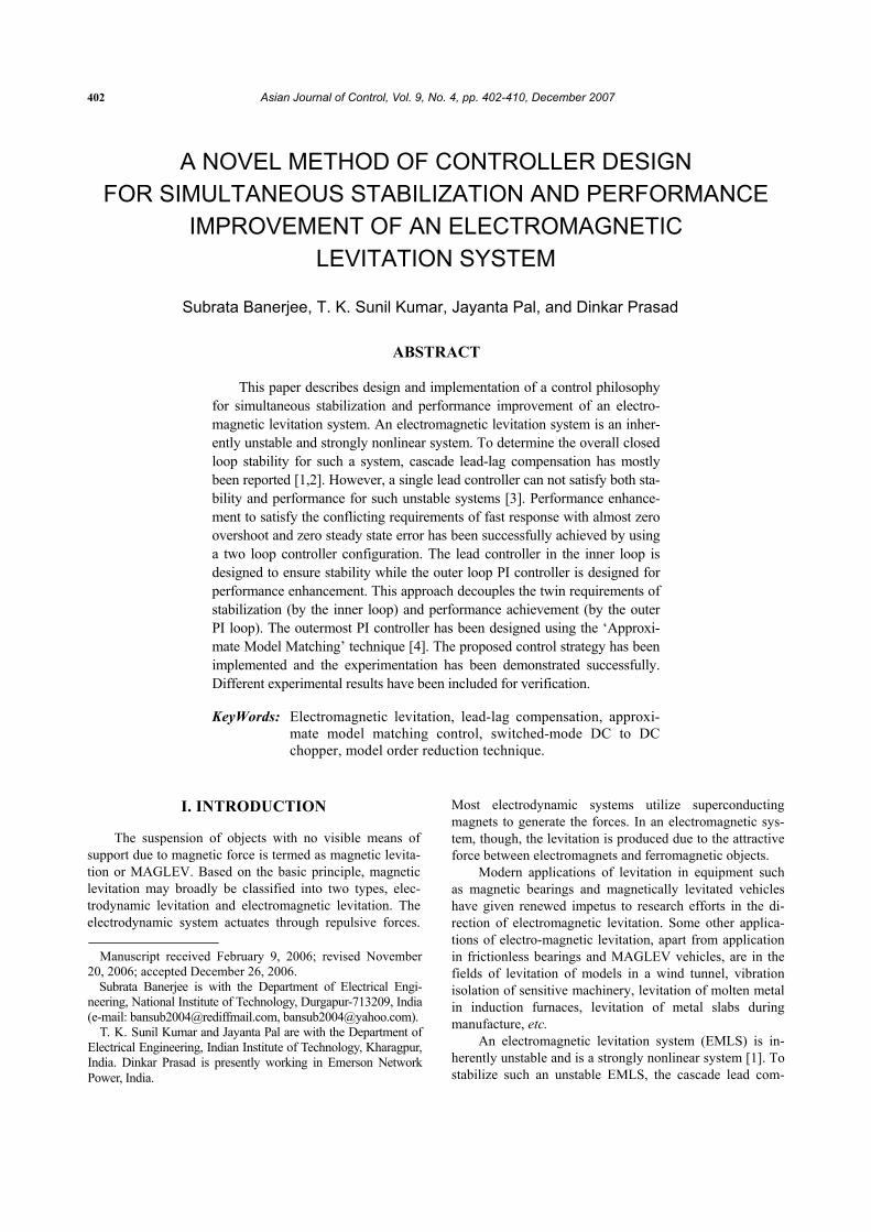
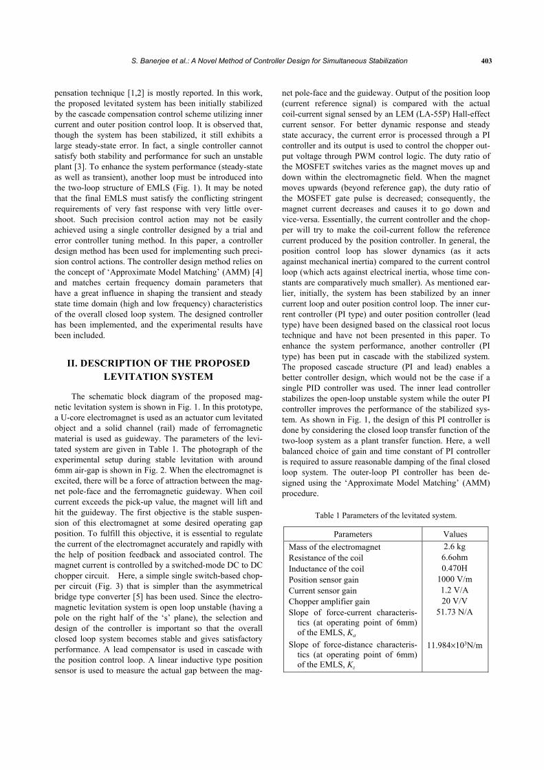
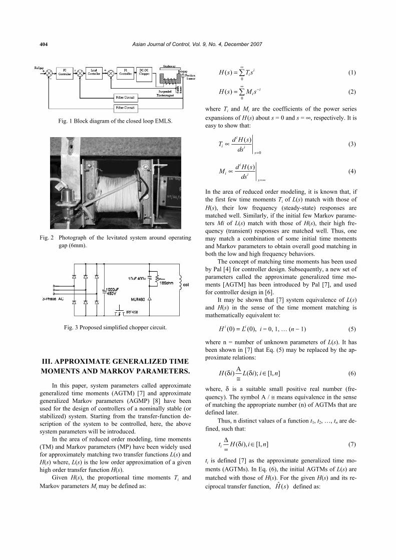
The schematic block diagram of the proposed mag-netic levitation system is shown in Fig. 1. In this prototype, a U-core electromagnet is used as an actuator cum levitated object and a solid channel (rail) made of ferromagnetic material is used as guideway. The parameters of the levi-tated system are given in Table 1. The photograph of the experimental setup during stable levitation with around 6mm air-gap is shown in Fig. 2. When the electromagnet is excited, there will be a force of attraction between the mag-net pole-face and the ferromagnetic guideway. When coil current exceeds the pick-up value, the magnet will lift and hit the guideway. The first objective is the stable suspen-sion of this electromagnet at some desired operating gap position. To fulfill this objective, it is essential to regulate the current of the electromagnet accurately and rapidly with the help of position feedback and associated control. The magnet current is controlled by a switched-mode DC to DC chopper circuit. Here, a simple single switch-based chop-per circuit (Fig. 3) that is simpler than the asymmetrical bridge type converter [5] has been used. Since the electro-magnetic levitation system is open loop unstable (having a pole on the right half of the ‘s’ plane), the selection and design of the controller is important so that the overall closed loop system becomes stable and gives satisfactory performance. A lead compensator is used in cascade with the position control loop. A linear inductive type position sensor is used to measure the actual gap between the mag-
net pole-face and the guideway. Output of the position loop (current reference signal) is compared with the actual coil-current signal sensed by an LEM (LA-55P) Hall-effect current sensor. For better dynamic response and steady state accuracy, the current error is processed through a PI controller and its output is used to control the chopper out-put voltage through PWM control logic. The duty ratio of the MOSFET switches varies as the magnet moves up and down within the electromagnetic field. When the magnet moves upwards (beyond reference gap), the duty ratio of the MOSFET gate pulse is decreased; consequently, the magnet current decreases and causes it to go down and vice-versa. Essentially, the current controller and the chop-per will try to make the coil-current follow the reference current produced by the position controller. In general, the position control loop has slower dynamics (as it acts against mechanical inertia) compared to the current control loop (which acts against electrical inertia, whose time con-stants are comparatively much smaller). As mentioned ear-lier, initially, the system has been stabilized by an inner current loop and outer position control loop. The inner cur-rent controller (PI type) and outer position controller (lead type) have been designed based on the classical root locus technique and have not been presented in this paper. To enhance the system performance, another controller (PI type) has been put in cascade with the stabilized system. The proposed cascade structure (PI and lead) enables a better controller design, which would not be the case if a single PID controller was used. The inner lead controller stabilizes the open-loop unstable system while the outer PI controller improves the performance of the stabilized sys-tem. As shown in Fig. 1, the design of this PI controller is done by considering the closed loop transfer function of the two-loop system as a plant transfer function. Here, a well balanced choice of gain and time constant of PI controller is required to assure reasonable damping of the final closed loop system. The outer-loop PI controller has been de-signed using the ‘Approximate Model Matching’ (AMM) procedure.
Table 1 Parameters of the levitated system.
Parameters Values Mass of the electromagnet Resistance of the coil Inductance of the coil Position sensor gain Current sensor gain Chopper amplifier gain Slope of force-current characteris-
tics (at operating point of 6mm) of the EMLS, Ka
Slope of force-distance characteris-tics (at operating point of 6mm) of the EMLS, Kz
2.6 kg 6.6ohm 0.470H
1000 V/m 1.2 V/A 20 V/V
51.73 N/A
11.984×10³N/m
404 Asian Journal of Control, Vol. 9, No. 4, December 2007
Fig. 1 Block diagram of the closed loop EMLS.
Fig. 2 Photograph of the levitated system around operating
gap (6mm).
Fig. 3 Proposed simplified chopper circuit.
III. APPROXIMATE GENERALIZED TIME MOMENTS AND MARKOV PARAMETERS.
In this paper, system parameters called approximate generalized time moments (AGTM) [7] and approximate generalized Markov parameters (AGMP) [8] have been used for the design of controllers of a nominally stable (or stabilized) system. Starting from the transfer-function de-scription of the system to be controlled, here, the above system parameters will be introduced.
In the area of reduced order modeling, time moments (TM) and Markov parameters (MP) have been widely used for approximately matching two transfer functions L(s) and H(s) where, L(s) is the low order approximation of a given high order transfer function H(s).
Given H(s), the proportional time moments Ti and Markov parameters Mi may be defined as:
0( ) i
iH s T s∞
= ∑ (1)
0( ) i
iH s M s∞
−= ∑ (2)
where Ti and Mi are the coefficients of the power series expansions of H (s) about s = 0 and s = ∞, respectively. It is easy to show that:
0
( )i
i is
d H sTds =
∝ (3)
( )i
i is
d H sMds =∞
∝ (4)
In the area of reduced order modeling, it is known that, if the first few time moments Ti of L(s) match with those of H(s), their low frequency (steady-state) responses are matched well. Similarly, if the initial few Markov parame-ters Mi of L(s) match with those of H(s), their high fre-quency (transient) responses are matched well. Thus, one may match a combination of some initial time moments and Markov parameters to obtain overall good matching in both the low and high frequency behaviors.
The concept of matching time moments has been used by Pal [4] for controller design. Subsequently, a new set of parameters called the approximate generalized time mo-ments [AGTM] has been introduced by Pal [7], and used for controller design in [6].
It may be shown that [7] system equivalence of L(s) and H(s) in the sense of the time moment matching is mathematically equivalent to:
(0) (0),i iH L= i = 0, 1, … (n − 1) (5)
where n = number of unknown parameters of L(s). It has been shown in [7] that Eq. (5) may be replaced by the ap-proximate relations:
( ) ( ); [1, ]H i L i i nΑδ δ ∈≅
(6)
where, δ is a suitable small positive real number (fre-quency). The symbol A / ≅ means equivalence in the sense of matching the appropriate number (n) of AGTMs that are defined later.
Thus, n distinct values of a function t1, t2, …, tn are de-fined, such that:
( ), [1, ]it H i i nΔ δ ∈=
(7)
ti is defined [7] as the approximate generalized time mo-ments (AGTMs). In Eq. (6), the initial AGTMs of L(s) are matched with those of H(s). For the given H(s) and its re-ciprocal transfer function, ˆ ( )H s defined as:
S. Banerjee et al.: A Novel Method of Controller Design for Simultaneous Stabilization 405
ˆ ( ) (1/ )H s H s= (8)
The expansion of ˆ ( )H s about s = 0 gives:
0
ˆ ˆ( ) iiH s T s
∞= ∑ (9)
It can easily be seen that the coefficients of the powers of s−i in the negative power series expansion of H (s) in Eq. (2) are the same as those of the powers of s
i in the positive power series expansion of ˆ ( )H s in Eq. (9). In other words, it can be stated that the Markov parameters of H (s) can be obtained by expanding either H (s) about s = ∞ or
ˆ ( )H s about s = 0.
Let 0
ˆˆ( ) iiL s s
∞= θ∑ (about s = 0) (10)
Then, it follows that if
ˆ ˆ(0) (0)i iH L= for [1, ]i n∈ , (11)
then the first n time-moments of ˆ( )L s (or equivalently, the first n Markov parameters of L(s), the original reduced model) will coincide with the first n time-moments of
ˆ ( )H s (or equivalently, the first n Markov parameters of H (s), the original high order system).
Using the results of Pal [7], the exact relations in Eq. (11) may be replaced by:
ˆ ˆ( ) ( )H i L iδ = δ , [1, ]i n∈ (12)
where δ is (as before) a suitable small positive real number (frequency).
By analogy, one may define:
ˆ ( ), [1, ]im H i i nΔ= δ ∈ (13)
where, mi is a new set of parameters called the approximate generalized Markov parameters (AGMP) [8], in the same spirit as that of AGTM [7].
It may be noted that a small δ for the reciprocal ˆ ( )H s in Eq. (13) corresponds to a large value of (1/δ) in
the original H(s) in Eq. (7). Thus, if one chooses a small value of δ = δt, in Equation (7), the AGTM’s are obtained; while, if one chooses a large value of δ = δm in Eq. (7), one actually obtains the AGMP’s in Eq. (13) for (δ = 1/δm). In this paper, for the EMLS considered, the PI controller in the outermost loop has been designed by matching the ap-propriate number of AGMPs to ensure good transient (high frequency) matching to yield a very fast response with neg-ligible overshoot and also zero steady-state error. As dis-cussed in the next section of this paper, AGMPs have been matched for controller design purpose.
IV. APPROXIMATE MODEL MATCHING METHOD OF CONTROLLER DESIGN
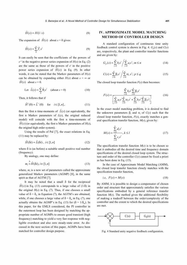
A standard configuration of continuous time unity feedback control system is shown in Fig. 4. Gp(s) and C(s) are, respectively, the plant and controller transfer functions and are given by:
0 0( ) ;
m ni i
p i ii i
G s b s a s m n= =
= ≤∑ ∑ (14)
0 0( ) ;
p qi i
i ii i
C s s s p q= =
= β α ≤∑ ∑ (15)
The closed loop transfer function F(s) then becomes:
0 0
0 0 0 0
( )
pmi i
i ii i
q pn mi i i i
i i i ii i i i
b s sF s
a s s b s s
= =
= = = =
β=⎡ ⎤α + β⎢ ⎥⎣ ⎦
∑ ∑
∑ ∑ ∑ ∑ (16)
In the exact model matching problem, it is desired to find the unknown parameters βi and αi of C(s) such that the closed loop transfer function, F(s), exactly matches a gen-eral specification transfer function, M(s), given by:
0
0
( ) ,
ki
ii
li
ii
d sM s k l
c s
=
=
= ≤∑
∑ (17)
The specification transfer function M(s) is to be chosen so that it embodies all the desired time and frequency domain specifications of the desired closed loop system. The struc-ture and order of the controller C(s) cannot be fixed a priori as has been done in Eq. (15).
In the case of Approximate Model Matching (AMM), the closed loop transfer function closely matches with the specification transfer function,
i.e, ( ) ( )F s M s≈ (18)
By AMM, it is possible to design a compensator of chosen order and structure that approximately satisfies the various specifications embodied by a general reference transfer function M(s). The method gives the additional flexibility of making a tradeoff between the order/complexity of the controller and the extent to which the desired specifications are met.
Fig. 4 Standard unity negative feedback configuration.
C(s) Gp(s) +
−
406 Asian Journal of Control, Vol. 9, No. 4, December 2007
The concept of Approximate Model Matching (AMM) has been widely used in the area of reduced order modeling [7,8]. In the frequency domain, model order reduction seeks to find an approximate low order transfer function L(s) from a given high order transfer function H(s), such that:
( ) ( )L s H s≈ , in some sense. (19)
In the classical Pade approximation (CPA) technique of model order reduction, the initial few time-moments (TM) and / or Markov parameters (MP) of the respective systems L(s) and M(s) are made identical. In the case of approxi-mate model matching type of controller design procedure using the CPA technique [4], one needs to match the initial few TMs and MPs on both sides of Eq. (18).
To design the controller using approximate general-ized time moments (AGTM) [8], the first important step is the choice of a reference model. The expected improve-ment in the system performance is depicted in the desired model. If the specifications are too rigid, then the resulting controller may be very complex and/or the control effort may be too large. Given a plant and a reference model, the AGTM based design method described below directly yields a low-order implementable compensator that cap-tures the essential low-frequency characteristics of the de-sired model M(s). The major steps of the controller design method are described below.
Step 1. A closed loop reference model transfer function M(s) that satisfies the desired specifications, e.g. for a ra-tional, stable, minimum phase plant, a reference model M(s) = 1/(1 + s)2 may be chosen to give a large gain margin, 75° phase margin, 6s settling time, −40 dB cut-off rate, etc.
Step 2. A general form for the controller is taken as follows:
20 1 2
20 1 2
.........( )
.......
pp
s s sC s
s s sβ + β + β + + β
=α + α + α + + α
(20)
where the unknown parameters βi and αi are to be deter-mined and, in general, p ≤ q.
Step 3. For the system in Fig. 4, the closed loop transfer function F(s) is as given in Eq. (16). For the closed loop system to satisfy the reference model specifications, F(s) should be equivalent to M(s) in some sense. In the pro-posed method, we find C(s) such that F(s) and M(s) have identical initial (p + q + 2) AGTMs,
i.e, ( ) ( )A
F s M s≅ (21)
where the symbol A≅ means equivalence in the sense of
matching the appropriate number of AGTMs.
Step 4. From M(s), the equivalent open-loop model M0(s) is derived. Then, M0(s) along with a unity negative feed-back would equal M(s)
or; 0
0
( )( )1 ( )
M sM sM s
=+
(22)
Thus, we get 0( )( )
1 ( )M sM s
M s=
− (23)
From Eq. (17), we get:
00
0 0
( )
kj
jj
l kj j
j jj j
d sM s
c s d s
=
= =
=−
∑
∑ ∑ (24)
Step 5. The open loop equivalent expression for Eq. (21) becomes:
0( ) ( ) ( )A
pG s C s M s≅ (25)
Using Eqs. (14), (15), and (24) we have:
0 0 0
0 00 0
pm kj j j
j j jj j j
q l kn j jj jj jj j
j jj j
b s s d s
c s d sa s s
= = =
= == =
β=
−α
∑ ∑ ∑
∑ ∑∑ ∑
0 0 0 0( )
p m l kj j j j
j j j jj j j j
s b s c s d s= = = =
⎡ ⎤β −⎢ ⎥
⎣ ⎦∑ ∑ ∑ ∑
0 0 0
q n kj j j
j j jj j j
s a s d s= = =
⎡ ⎤= α ⎢ ⎥
⎣ ⎦∑ ∑ ∑ (26)
From the definition of AGTM, by putting s = βi where δi = δ.i, i ∈[1, p + q + 2]; where δ is the point of expansion about the origin,
0 0 0 0( ) ( ) ( ) ( )
p m l kj j j j
j j j jj j j j
i b i c i d i= = = =
⎡ ⎤⎛ ⎞β δ δ δ − δ⎢ ⎥⎜ ⎟
⎢ ⎥⎝ ⎠⎣ ⎦∑ ∑ ∑ ∑
0 0 0( ) ( ) ( )
q n kj j j
j j jj j j
i a i d i= = =
⎡ ⎤= α δ δ δ⎢ ⎥
⎣ ⎦∑ ∑ ∑
for, i = 1, 2 …, ( 2)p q+ + (27)
Without loss of generality, one may choose α0 = 1. Then the above equation may be written as:
0 0 0 0( ) ( ) ( ) ( )
p m l kj j j j
j j j jj j j j
i b i c i d i= = = =
⎡ ⎤⎛ ⎞β δ δ δ − δ⎢ ⎥⎜ ⎟
⎢ ⎥⎝ ⎠⎣ ⎦∑ ∑ ∑ ∑
1 0 0( ) ( ) ( )
q n kj j j
j j jj j j
i a i d i= = =
⎡ ⎤− α δ δ δ⎢ ⎥
⎣ ⎦∑ ∑ ∑
0 0( ) ( )
n kj j
j jj j
a i d i= =
⎡ ⎤= δ δ⎢ ⎥⎣ ⎦∑ ∑
for i = 1, 2, …, ( 1)p q+ + (28)
S. Banerjee et al.: A Novel Method of Controller Design for Simultaneous Stabilization 407
In the above equation, ai, bi, ci and di are known pa-rameters (coefficients of the plant and reference model transfer functions) and terms within parentheses [•] will be known constants, thus giving a set of (p + q + 1) linear simultaneous algebraic equations in the unknown controller parameters βi and αi.
Step 6. The linear equations are solved to obtain the con-troller parameters. Step 7. If the closed loop time or frequency responses are not satisfactory with this controller, then structure of the controller is to be increased. Step 8. If the desired specifications are satisfied, then the process is stopped.
In some cases, the use of only AGTM matching may result in poor high frequency (transient response) matching. Then, use of AGMP [8] matching may be required in addi-tion to AGTM matching. Denoting an AGMP expansion point as δm, the design equations may be derived from Eq. (15) as under by equating the appropriate number of AGMPs on both of its sides:
(1/ ) (1/ ) (1/ )m mm
p s ssG s C s M s
Α
=δ =δ=δ• ≅ (29)
where δm is a small positive number near the origin (s = 0). It may be noted that Eq. (28) may be used instead of Eq. (29), where δ is a corresponding large positive number i.e. δ = 1/δm. Hence, in Eq. (28), we use δi = δ.i = 1/δm. So, the same set of (p + q + 1) equations as in Eq. (28) may be conveniently used by choosing δ = small positive number for matching AGTMs, and δ = large positive number = 1/δm for matching the AGMPs. When a controller that gives AGTM as well as AGMP matching is desired, l number of equations from (28) are formed for δ = δt, a small positive number; and r number of equations from (28) are formed for δ = 1/δm, a large posi-tive number; such that (l + r) = (p + q + l). Then, l number of AGTMs and r number of AGMPs will be matched. For the controller design problem, l and r may be varied depending on the number of AGTMs and AGMPs desired to be matched. The choice of the number of AGTMs and AGMPs to be matched depends on the type of closed loop system response that one desires (speed of response, damping, over-shoot, etc.) along with the primary concern of stability pres-ervation. Thus, one may design a family of controllers of a particular order and structure by changing the values of l and r. The simplest controller that gives the best matching and that can be easily implemented is then finally chosen.
V. SIMULATED AND EXPERIMENTAL RESULTS
The dynamic equations of the levitated system are nonlinear. The nonlinear equations have been linearised
about a suitable operating point. Taking controlled current source as the excitation of the magnet-coil the trans-fer-function of the levitated system (plant) may be written in the following form [1]:
2( )
a
z
KmG s
Ksm
⎛ ⎞⎜ ⎟⎝ ⎠=
⎛ ⎞−⎜ ⎟⎝ ⎠
(30)
where the two force constants Fa and Kz are, respectively, the slope at the operating point of the force-current and force-distance characteristics of the electromagnetic sus-pension system having a mass of ‘m’ and can be deter-mined experimentally.
From Table-1, for the operating air-gap of 6 mm, the plant Gp (s) has one stable pole at s = −67.89 and an unsta-ble pole at s = 67.89. The objective is to design a phase lead compensator so that the overall closed loop system becomes stable. The pole and zero are to be placed on the negative real axis, and there are many possible pole-zero locations for stabilizing the system. The phase-lead com-pensator design procedure in this case is to place the zero of the compensator between 0 and –67.89 on the real axis of the s-plane, while the pole of the compensator is placed about 10 times to the left of the zero position. While de-signing the position controller, the dynamics of the inner-most current loop are neglected. The transfer function of the designed lead controller for an operating air-gap of 6 mm is given by:
4.6( 64)( )( 500)pc
sG ss
+=+
(31)
The transfer function of the coil at the nominal operating point (6mm) gap is found to be:
1( )(6.6 0.692 )cG s
s=
+ (32)
For designing the current controller (PI type), the inner-most current loop is considered separately. The loop-gain of the current loop can be written as:
1( ) 24(6.6 0.692 )
ii p
KGH s Ks s
⎛ ⎞= × + ×⎜ ⎟ +⎝ ⎠ (33)
After converting Eq. (33) in the frequency domain, from the phase angle criterion one can write:
0 1 1 090 tan tan (0.1048 ) 180g pg
i
w Kw
K− −⎛ ⎞
− − − + = Φ⎜ ⎟⎝ ⎠
(34)
where Φ is the phase margin (PM) and wg is the gain cross-over frequency.
From the magnitude criterion,
408 Asian Journal of Control, Vol. 9, No. 4, December 2007
2
2
113.636 1
1 (0.1048 )
g p
ii
g g
w KK
Kw w
⎛ ⎞+ ⎜ ⎟⎝ ⎠× × =
+ (35)
Assuming phase margin is 60 degree at a gain crossover frequency of 100Hz, one can find that Kp = 15.54 and Ki = 5846.89.
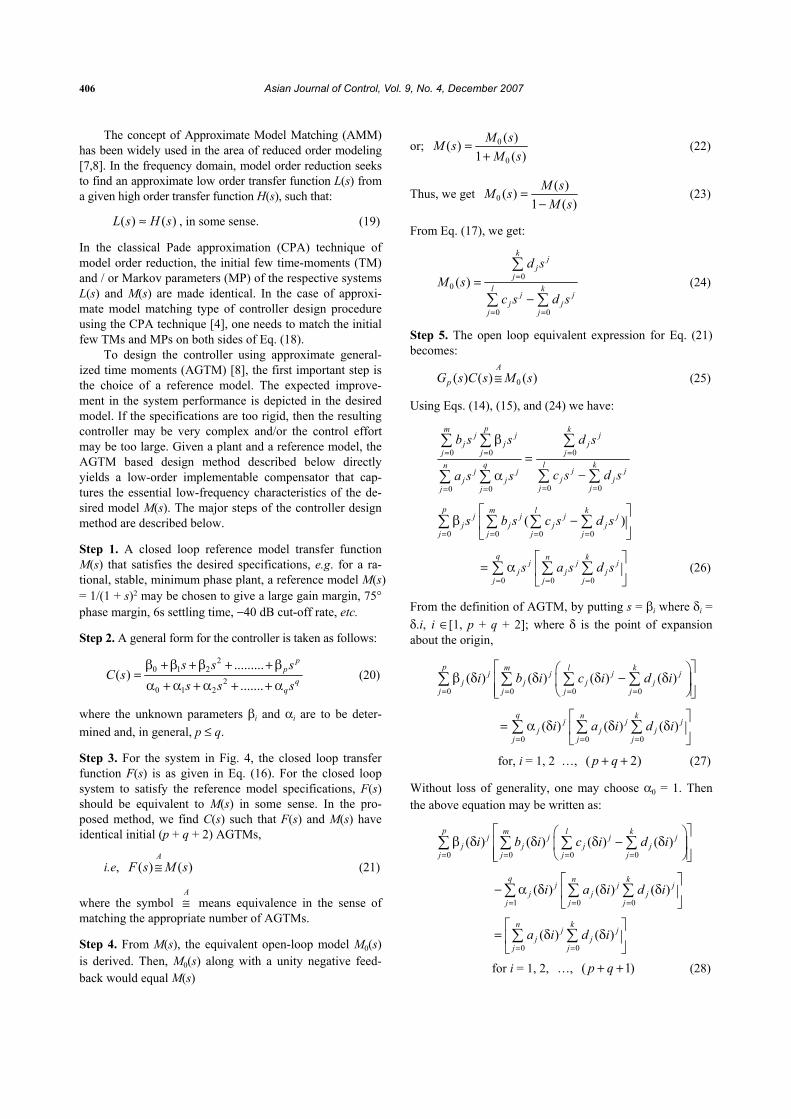
The SIMULINK model of the overall closed loop sys-tem is shown in Fig. 5. The transfer functions of the dif-ferent blocks of the model have been found experimentally. The closed loop stabilized system transfer function with the cascade lead controller (considering the two inner loops of Fig. 5) is treated as the plant transfer function Gp (s) as mentioned in Eq. (1) and is given below:
Gp (s) =
(2.099e007 s3 + 1.973e010 s2 + 5.124e012 s + 2.526e014) (s6 + 1549 s5 + 9.971e005 s4 + 3.328e008 s3 + 6.704e010 s2 + 7.671e012 s + 2.717e014) (36)
The outermost PI controller is used for improving the overall closed loop performance and has been designed by the ‘Approximate Model Matching’ (AMM) method of controller design.
The desired model transfer function M(s) is chosen as: 2
2( )( )
M ss
λ=+ λ
(37)
For obtaining a critically damped fast rise system, we
choose λ = 50, which gives:
22500( )
100 2500M s
s s=
+ + (38)
Since a very fast response with minimal overshoot is de-manded from the final response of the stabilized EMLS, matching only the initial few AGMPs is found to yield the controller that satisfies all the specifications.
For δ = 125 and 100; the resulting Eq. (28) are solved to yield the following PI controller.
1 1 / (0.0576 21.11/ )p IK K s s+ = +
0.0576( 366.49)ss+= (39)
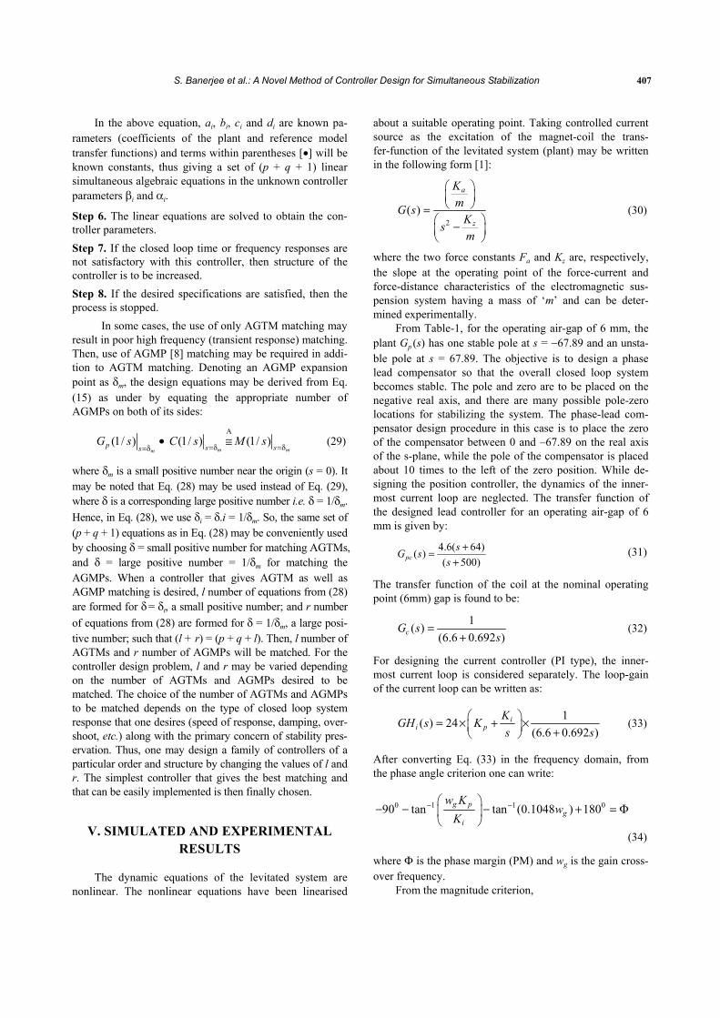
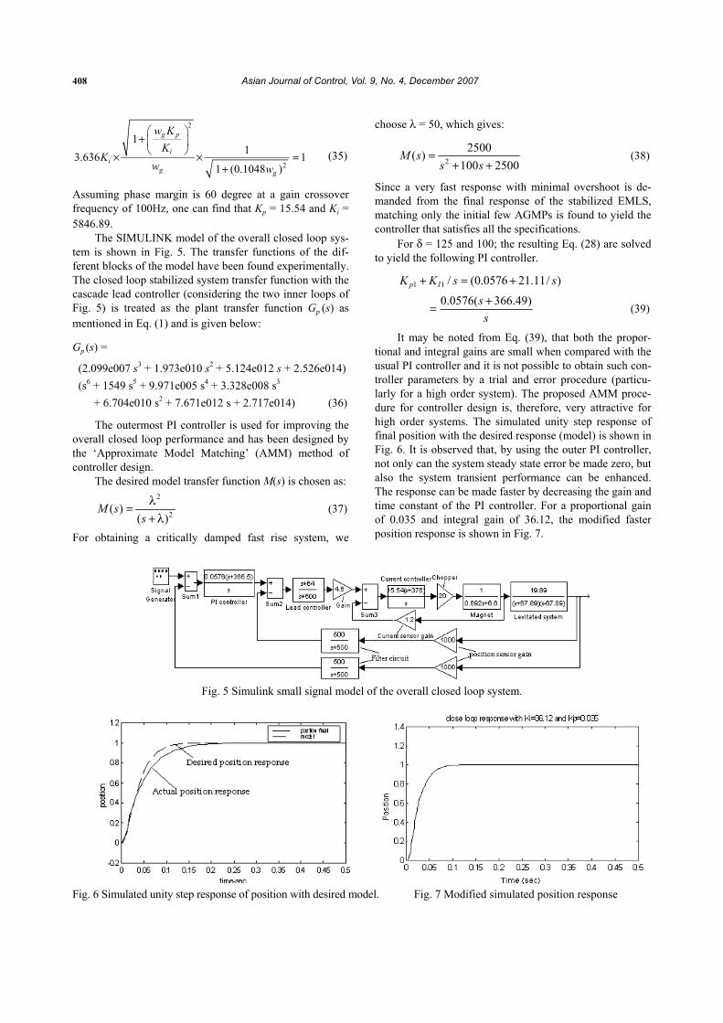
It may be noted from Eq. (39), that both the propor-tional and integral gains are small when compared with the usual PI controller and it is not possible to obtain such con-troller parameters by a trial and error procedure (particu-larly for a high order system). The proposed AMM proce-dure for controller design is, therefore, very attractive for high order systems. The simulated unity step response of final position with the desired response (model) is shown in Fig. 6. It is observed that, by using the outer PI controller, not only can the system steady state error be made zero, but also the system transient performance can be enhanced. The response can be made faster by decreasing the gain and time constant of the PI controller. For a proportional gain of 0.035 and integral gain of 36.12, the modified faster position response is shown in Fig. 7.
Fig. 5 Simulink small signal model of the overall closed loop system.
Fig. 6 Simulated unity step response of position with desired model. Fig. 7 Modified simulated position response
S. Banerjee et al.: A Novel Method of Controller Design for Simultaneous Stabilization 409
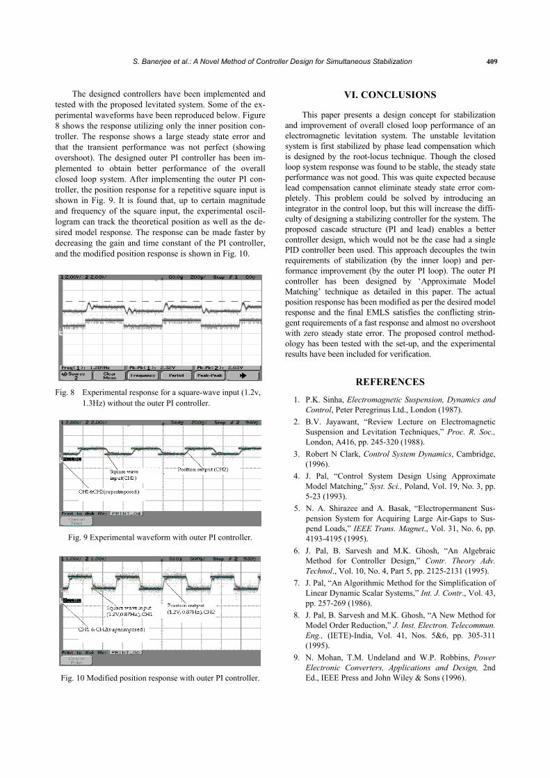
The designed controllers have been implemented and tested with the proposed levitated system. Some of the ex-perimental waveforms have been reproduced below. Figure 8 shows the response utilizing only the inner position con-troller. The response shows a large steady state error and that the transient performance was not perfect (showing overshoot). The designed outer PI controller has been im-plemented to obtain better performance of the overall closed loop system. After implementing the outer PI con-troller, the position response for a repetitive square input is shown in Fig. 9. It is found that, up to certain magnitude and frequency of the square input, the experimental oscil-logram can track the theoretical position as well as the de-sired model response. The response can be made faster by decreasing the gain and time constant of the PI controller, and the modified position response is shown in Fig. 10.
Fig. 8 Experimental response for a square-wave input (1.2v,
1.3Hz) without the outer PI controller.
Fig. 9 Experimental waveform with outer PI controller.
Fig. 10 Modified position response with outer PI controller.
VI. CONCLUSIONS
This paper presents a design concept for stabilization and improvement of overall closed loop performance of an electromagnetic levitation system. The unstable levitation system is first stabilized by phase lead compensation which is designed by the root-locus technique. Though the closed loop system response was found to be stable, the steady state performance was not good. This was quite expected because lead compensation cannot eliminate steady state error com-pletely. This problem could be solved by introducing an integrator in the control loop, but this will increase the diffi-culty of designing a stabilizing controller for the system. The proposed cascade structure (PI and lead) enables a better controller design, which would not be the case had a single PID controller been used. This approach decouples the twin requirements of stabilization (by the inner loop) and per-formance improvement (by the outer PI loop). The outer PI controller has been designed by ‘Approximate Model Matching’ technique as detailed in this paper. The actual position response has been modified as per the desired model response and the final EMLS satisfies the conflicting strin-gent requirements of a fast response and almost no overshoot with zero steady state error. The proposed control method-ology has been tested with the set-up, and the experimental results have been included for verification.
REFERENCES
1. P.K. Sinha, Electromagnetic Suspension, Dynamics and Control, Peter Peregrinus Ltd., London (1987).
2. B.V. Jayawant, “Review Lecture on Electromagnetic Suspension and Levitation Techniques,” Proc. R. Soc., London, A416, pp. 245-320 (1988).
3. Robert N Clark, Control System Dynamics, Cambridge, (1996).
4. J. Pal, “Control System Design Using Approximate Model Matching,” Syst. Sci., Poland, Vol. 19, No. 3, pp. 5-23 (1993).
5. N. A. Shirazee and A. Basak, “Electropermanent Sus-pension System for Acquiring Large Air-Gaps to Sus-pend Loads,” IEEE Trans. Magnet., Vol. 31, No. 6, pp. 4193-4195 (1995).
6. J. Pal, B. Sarvesh and M.K. Ghosh, “An Algebraic Method for Controller Design,” Contr. Theory Adv. Technol., Vol. 10, No. 4, Part 5, pp. 2125-2131 (1995).
7. J. Pal, “An Algorithmic Method for the Simplification of Linear Dynamic Scalar Systems,” Int. J. Contr., Vol. 43, pp. 257-269 (1986).
8. J. Pal, B. Sarvesh and M.K. Ghosh, “A New Method for Model Order Reduction,” J. Inst. Electron. Telecommun. Eng., (IETE)-India, Vol. 41, Nos. 5&6, pp. 305-311 (1995).
9. N. Mohan, T.M. Undeland and W.P. Robbins, Power Electronic Converters, Applications and Design, 2nd Ed., IEEE Press and John Wiley & Sons (1996).
410 Asian Journal of Control, Vol. 9, No. 4, December 2007
Subrata Banerjee was born in 1968. He received B.E. (Electrical) from NBU (West Bengal), India in the year 1989, M.E. (Electrical Machines) degree from B.E. College, Howrah, India in the year 1994 and Ph.D in Electrical Engineering from I.I.T., Kharagpur India in the year
2005. Dr. Banerjee was a research fellow in DRDL, Hy-derabad, India sponsored project for two and half years in Control Systems Laboratory, Department of Electrical En-gineering, JU, Kolkata, India. Presently, he is Assistant Professor of Electrical Engineering Department in National Institute of Technology, Durgapur. He has a total twelve years teaching, five years research and one year industrial experience. He has published a numbers of research papers in National/International Conference Records/Journals. He received ‘Best application paper award’ and ‘Best presen-tation award for a session’ at NSC, held at I.I.T. Kharagpur, India, 2003. His research interest includes Control systems, Power Electronics and Magnetic Levitation.
T.K.Sunil Kumar was born in 1974 at Calicut, India. He received the B.Tech in electrical engineering in 1997 from N.S.S College of Engineering, Palakkad (Calicut University) and M.Tech in Power System in 2001 from Regional Institute of
Technology, Jamshedpur (Ranchi University). Since 2001, he has been pursuing research work for his Ph.D in Elec-trical Engineering at Indian Institute of Technology, Kharagpur. He is a life member of Systems Society of In-dia. His main research interests includes application of control theory and computers to power system, model order reduction, genetic algorithm, PID tuning, random search optimization, controller deign in 2-DOF configuration and interval systems.
Jayanta Pal was born in Calcutta, India in 1948. He received the B.Sc. and M.Sc de-grees in Electrical Engineering from the Institute of Technology, BHU, India in 1969 and 1971; the M.Sc. and DIC from Imperial College, UK, in 1974 and the PhD in Electrical Engineering from Roorkee
University, India, in 1981.From 1974 to 1987, he served as Lecturer and Reader in electrical engineering at University of Roorkee, India. He is currently a Professor of Electrical Engineering at IIT, Kharagpur, India. His Biographical in-clusions are in International Who’s Who of Contemporary Achievement, UK (1984); 5000 Personalities of the World, USA (1987), International Book of Honor, USA, (1989,1991); Reference Asia: Asia’s Who’s Who of Men and Women of Achievment, India (1989), Reference India, India (1991), Biography International, India (1993); Indo-American Who’s Who, India (1994) etc. He is a mem-ber of the IEEE, Life Member of the System Society of India, and is presently the President of the Local Chapter of the System Society of India. His main research interests in-clude large-scale systems, model-order reduction, digital control, system theory, neural networks, genetic algorithms, electromagnetic levitation and electrical power system.
Dinkar Prasad was born in 1960. He received his B.Tech (Electrical) degree from Indian Institute of Technology, Kanpur in 1981. After graduation he served with TELCO, Jamshedpur as plant maintenance Engineer for 6 years. While with TELCO, he took study leave and did
M.Tech (Electrical, in 1986) from IIT, Kharagpur. Later he did his doctoral research in the same department and was awarded PhD degree in 1992. From 1991 to 1992 he briefly served as Lecturer in the Electrical Eng. Dept. of IIT, Kharagpur. Later (1992-1997) he joined IIT, Bombay as Assistant Professor. He was with Dept. of Electrical Engineering, Univ. of Minnesota, Minneapolis, USA as a Post-doctoral fellow from 1997 to 2000. In 2000 he joined IIT, Kharagpur as Associate Professor and is presently continuing in the same capacity. He has guided two PhD students and more than twenty Masters students in the area of Power Electronics and Machine drives. He has also worked on some industrial projects in India and USA as consultant.