Embed Size (px)
Citation preview

A novel method for studying the buckling of nanotubesconsidering geometrical imperfections
N. M. Anoop Krishnan • Debraj Ghosh
Received: 13 March 2014 / Accepted: 1 May 2014
� Springer-Verlag Berlin Heidelberg 2014
Abstract Buckling of nanotubes has been studied using
many methods such as molecular dynamics (MD), molec-
ular mechanics, and continuum-based shell theories. In
MD, motion of the individual atoms is tracked under
applied temperature and pressure, ensuring a reliable esti-
mate of the material response. The response thus simulated
varies for individual nanotubes and is only as accurate as
the force field used to model the atomic interactions. On
the other hand, there exists a rich literature on the under-
standing of continuum mechanics-based shell theories.
Based on the observations on the behavior of nanotubes,
there have been a number of shell theory-based approaches
to study the buckling of nanotubes. Although some of these
methods yield a reasonable estimate of the buckling stress,
investigation and comparison of buckled mode shapes
obtained from continuum analysis and MD are sparse.
Previous studies show that the direct application of shell
theories to study nanotube buckling often leads to errone-
ous results. The present study reveals that a major source of
this error can be attributed to the departure of the shape of
the nanotube from a perfect cylindrical shell. Analogous to
the shell buckling in the macro-scale, in this work, the
nanotube is modeled as a thin-shell with initial imperfec-
tion. Then, a nonlinear buckling analysis is carried out
using the Riks method. It is observed that this proposed
approach yields significantly improved estimate of the
buckling stress and mode shapes. It is also shown that the
present method can account for the variation of buckling
stress as a function of the temperature considered. Hence,
this can prove to be a robust method for a continuum
analysis of nanosystems taking in the effect of variation of
temperature as well.
1 Introduction
Study of buckling of nanotubes has gained considerable
interest in the recent past. Owing to their slender structure,
nanotubes buckle and fail before reaching the ultimate
strength, often resulting in an early collapse of the struc-
ture. Hence, it is essential to study the buckling behavior of
nanotubes as the understanding of the theory of buckling
finds applications in nanoscale devices such as probe tips
[1–3], sensors, and nano-composites with nanotubes as
reinforcement to improve mechanical properties [4] or to
introduce piezoelectric properties [5]. Therefore, in addi-
tion to the studies on synthesis and mechanical properties
of nanotubes [6, 7], several experimental and simulation
studies have been carried out on the buckling of nanotubes
under axial-compressive loads [8–12]. Depending on the
length to diameter (L=D) ratio, nanotubes show three dif-
ferent buckling behavior. For instance, in [10], it was
reported that the carbon nanotubes (CNTs) show (1) wire-
like behavior for very long tubes, (2) shell buckling for
small aspect ratio (L=D� 1–20), and (3) Euler or column
buckling for intermediate L=D ratios. Computational
modeling of mechanics at nanoscale and buckling analysis
of nanotubes using such models have long been an
important area. There are ab-initio simulation methods
such as quantum mechanical or molecular dynamics (MD)
simulations—which are very accurate. But these simula-
tions are computationally expensive and hence cannot be
used for multiple simulations of nanotubes having different
N. M. Anoop Krishnan (&) � D. Ghosh
Department of Civil Engineering, Indian Institute of Science,
Bangalore 560012, India
e-mail: [email protected]
D. Ghosh
e-mail: [email protected]
123
Appl. Phys. A
DOI 10.1007/s00339-014-8489-x

dimensions and chiralities. There are simple continuum
mechanics-based models which are approximate yet more
economical. Such methods can make use of the rich and
vast literature and understanding of continuum mechanics
to predict the behavior of nanotubes individually and in a
system.
In MD simulations, the material is modeled at molecular
motion level and the computation amounts to solving a
large-coupled system of ordinary differential equations.
One of the pioneering work on MD simulations on nano-
tube buckling is [8], where the observations were explained
using a continuum shell theory. In [13], MD was used for
buckling and post-buckling analysis of nanotubes. How-
ever, studying more complicated and bigger systems using
an MD simulation may not be realistic. Thus, using the
knowledge that nanotube buckles similar to that of a shell,
researchers started developing theories to model the
nanotube from a continuum shell perspective. Several
attempts have been reported in this direction, such as
Timoshenko beam theory [14], thin-shell theories [11, 12,
15–18], a thin-shell theory followed by finite element
discretization [19], structural mechanics at atomistic level
[20–23], molecular statics [24–28], nonlocal elasticity [29,
30]. Based on these studies, it is found that the thin-shell
models [31] can be very useful in studying nanotube
buckling, primarily due to the similarity in shapes and
mechanical behavior between continuum shells and nano-
tubes. The effectiveness of various continuum-based
methods to analyze CNT buckling was studied in [32]. The
study revealed a variation in the estimation of buckling
strains among different methods. Hence, selection of an
appropriate shell theory and associated parameters is cru-
cial for accuracy of the estimates. The limitations of the
thin-shell theories in nanotube buckling estimation are
critically studied in [11, 16, 17], underlining the need for a
better method.
It will be demonstrated in this paper that for a nanotube
under axial compression, the classical thin-shell theory
overestimates the buckling stress and predicts the buckled
mode shape incorrectly. Similar observations were made in
the macroscopic engineering level for many years where
the experimental observations of buckling load of thin-
shells remained consistently lower than the estimates from
classical thin-shell theory [33]. Later on, the researchers
attributed this difference to the unavoidable presence of
initial imperfections in the structures, particularly the out-
of-roundness of the cylinder, locally or along the length of
the tube. This issue was resolved to a large extent in the
seminal thesis [34] by Koiter. Through an asymptotic
analysis of the post-buckling behavior he demonstrated that
the buckling load reduces dramatically with the increase in
initial imperfection. This work found numerous applica-
tions in the follow-up works on estimating a realistic
buckling load for various types of structures under various
loading conditions [15, 35–37]. Led by this success, Ko-
iter’s theory [34, 38, 39]—and more generally the theory of
thin-shell buckling considering initial imperfections (see
[33]), has been widely accepted as very reliable approaches
for accurate prediction buckling of thin-shells. A nanotube,
although modeled as a thin-shell, is essentially a collection
of finite number of atoms. Hence, it is not truly a contin-
uum. Furthermore, while equilibration, one or more
atom(s) can move out of the ideal cylindrical surface
leading to an initial structural imperfection in the form of
out-of-roundness along the length of the tube. Note that the
equilibration is carried out at a specific temperature and
hence, the degree of imperfection depends on the temper-
ature as well. Thus, usage of shell theories with a geometric
imperfection could serve as a potential direction for
improving the continuum mechanics-based analysis of
nanotube buckling incorporating the effect of temperature
on the nanotube buckling. There are a few continuum-
based models such as nonlocal elasticity used to study the
effect of temperature on the behavior of nanotubes[40–43].
However, to the best of authors’ knowledge, the effect of
out-of-roundness on the buckling stress of nanotube has not
yet been explored thus far by any previous studies, and
therefore the present work is aimed at this direction. Note
that the geometric imperfections considered here refer to
the out-of-roundness of the CNTs from that of the perfect
structure and are not related to the other imperfections or
defects such as missing-atom [44], Stone-Wales [45].
This paper is organized as follows. The theory of thin-
shells and the effect of initial imperfections are discussed
in Sect. 2. The theory of analysis of nanotubes using finite
element (FE) method is also discussed there. In Sect. 3, the
modeling and implementation of MD and FE methods to
study the buckling behavior of nanotubes are explained.
The major results obtained from thin-shell, shell with
imperfections, FE analysis and MD are discussed in Sect. 4
followed by concluding remarks in Sect. 5.
2 Theory
Shell theories have been used extensively to study the
buckling of nanotubes. Few commonly used theories
include thin-shell, first order shear deformation, and
nonlocal elasticity. Here, the theory of thin-shell is
explained followed by the Koiter’s theory of imperfection
in shells. The computational modeling of the nanotubes
with and without imperfection, respectively, to study shell
buckling using linear and nonlinear methods using the FE
analysis is also explained. The numerical implementation
of the FE method is discussed in detail in the next
section.
N. M. A. Krishnan, D. Ghosh
123

2.1 Buckling theory for cylindrical thin-shells
Cylindrical shells under uniform compressive loading in
the axial direction buckle at loads much lower than the
crushing load. The stress corresponding to the minimum of
such loads is defined as the critical buckling stress. The
buckled shape of the shell may be symmetrical or asym-
metrical to the axis of the cylinder. In the case of a sym-
metrical buckling, the radial displacement w during
buckling can be assumed as
w ¼ �A sinmpx
lð1Þ
where l is the length of the cylinder along the X axis—the
axial direction, x is the coordinate along the X axis, A is the
amplitude of the radial displacement and m is an integer.
Assuming that the load during the buckling remains con-
stant, the buckling load per unit length immediately before
buckling, Ncr ¼ �0Eh is equated to the buckling load per
unit length immediately after buckling,
Ncr ¼ ½Eh=ð1� m2Þ�ð�1 þ m�2Þ, where m is the Poisson’s
ratio and E is the modulus of elasticity and h is the shell
thickness. Thus, the axial strain before buckling �0 is
related to the axial strain �1 and circumferential strain �2
after buckling as
�1 þ m�2 ¼ ð1� m2Þ�0 ð2Þ
Here, �2 can be written �2 ¼ �m�0 � ðw=aÞ ¼ �m�0 þðA=aÞ sin mpx=lð Þ where a is the radius of the cylinder. The
change in curvature in the axial plane is given as
vx ¼ Am2p2
l2sin
mpx
lð3Þ
Also, owing to the symmetrical buckling,
c ¼ vy ¼ vxy ¼ 0. Thus, the increase of strain energy dur-
ing buckling can be written as
DU ¼ �2phEm�0
Z l
0
A sinmpx
ldxþ pA2Ehl
2aþ A2 p4m4
2l2palD
ð4Þ
where D ¼ Eh3=12ð1� m2Þ is the flexural rigidity of the
cylinder. Now, the work done by the compressive force
during buckling is
DW ¼ 2pNcr mZ l
0
A sinmpx
ldxþ a
4A2 m2p2
l
0@
1A ð5Þ
This work done can be equated to the change in strain
energy of the cylinder to obtain the expression for the
buckling stress as
rcr ¼ Dm2p2
hl2þ El2
a2Dm2p2
� �ð6Þ
Since m can take any integer value, the wavelength of
deformation can be lower than the length of the cylinder.
Thus, the minimum value of rcr with respect to ðmp=lÞ can
be given as
rcr ¼Eh
affiffiffiffiffiffiffiffiffiffiffiffiffiffiffiffiffiffiffi3ð1� m2Þ
p ð7Þ
The location of this critical stress along the shell length is
at ðmp=lÞ ¼ Eh=a2Dð Þ1=4. Hence, it can be seen that the
critical buckling stress is independent of the length of the
cylinder. It can also be shown that the magnitude of critical
stress in the case of asymmetrical buckling is same as that
of symmetrical buckling [31].
2.2 Theory of shells with imperfection
Though the thin-shell equation gives a theoretical estimate
of the buckling stresses, the actual value obtained in
experiments varies from this. Such a variation from the
theoretical estimate is due to the presence of imperfections
in the initial conditions or the inaccuracies in ensuring the
conditions while conducting the experiments, for example,
imperfection in loading, shape, structure, and boundary
conditions. For imperfection sensitive structures, the vari-
ation of the shape of a shell from that of a perfect cylinder
can reduce the buckling stress. The imperfection sensitivity
of a structure was analyzed by Koiter by studying the
asymptotic form of a smooth potential energy function,
Pðq; k; aÞ, given by,
Pðq; k; aÞ ¼ ðc1 � a1aÞqþ ðc2 � a2aÞq2
þ ðcn � anaÞqn � kuð8Þ
where u ¼ b2ðq2 � a2Þ þ b4ðq4 � a4Þ is the generalized
displacement and ku corresponds to work done under
loading. c1; c2; cn; a1; a2; an and n are constants, q is the
parameter of the asymptotic expansion, k is the load
parameter characterizing either a single load or a system of
loads, and a is the small imperfection parameter. It should
be noted that n ¼ 3 for asymmetric bifurcation and n ¼ 4
for symmetric bifurcation. The equilibrium condition
oP=oqð Þ ¼ 0 yields,
c1 � a1aþ 2ðc2 � a2a� b2kÞqþ nðcn � anaÞqn�1
�4b4kq3 ¼ 0ð9Þ
Similarly, the critical load condition for the structure given
by o2P=oq2� �
¼ 0 yields,
A novel method for studying the buckling of nanotubes
123

2ðc2 � a2a� b2kÞ þ nðn� 1Þðcn � anaÞqn�2
�12b4kq2 ¼ 0ð10Þ
Applying the equilibrium and bifurcation conditions, and
neglecting higher-order terms, Eqs. (9) and (10) reduce to
k ¼ 1� k1
aq
� �� ðk2 þ k3Þqn�2 ð11Þ
k ¼ 1� ½ðn� 1Þk2 þ 3k3�qn�2 ð12Þ
respectively, where k1 ¼ a1=2c2, k2 ¼ ncn=2c2, k3 ¼ 0 for
n ¼ 3 and k3 ¼ 2b4=c2 6¼ 0 for other values of n. Using
elimination and substitution, k can be obtained as
k ¼ 1� aa0
� �m
ð13Þ
where a0 ¼ ½ðn� 2Þk2 þ 2k3�k�11 ½ðn� 1Þk2 þ 3k3��1=m
is a
constant, the exponent m is given by m ¼ ½ðn� 2Þ=ðn� 1Þ�and k ¼ Pmax=Pcr for a single load. Here, Pmax is the
maximum load at which the cylinder with imperfection
buckles and Pcr is the critical buckling load of a perfect
cylinder. The imperfection sensitivity is stronger when the
exponent m is smaller. Hence, for unstable symmetric
bifurcation (n ¼ 4 and m ¼ 2=3), the imperfection sensi-
tivity is more compared to asymmetric bifurcation (n ¼ 3
and m ¼ 1=2).
In the case of a shell with imperfection, the Eq. (13) can
be written as [39]
1� rrcr
� �¼ ad
rrcr
ð14Þ
Here, e ¼ d=h is the imperfection of the cylinder of
thickness h, with maximum amplitude of imperfection
being d. r is the buckling stress obtained for shell with
imperfection while rcr refers to the buckling stress of a
shell without imperfection. From Eq. (14), the buckling
stress r of a cylinder with imperfection, e, can be derived
as follows
r ¼ rcr
�1þ 3
4effiffiffiffiffiffiffiffiffiffiffiffiffiffiffiffiffiffiffi3ð1� m2Þ
p
�
ffiffiffiffiffiffiffiffiffiffiffiffiffiffiffiffiffiffiffiffiffiffiffiffiffiffiffiffiffiffiffiffiffiffiffiffiffiffiffiffiffiffiffiffiffiffiffiffiffiffiffiffiffiffiffiffiffiffiffiffiffiffiffiffiffiffiffiffiffiffiffiffi3
4effiffiffiffiffiffiffiffiffiffiffiffiffiffiffiffiffiffiffi3ð1� m2Þ
p2þ 3
4effiffiffiffiffiffiffiffiffiffiffiffiffiffiffiffiffiffiffi3ð1� m2Þ
p� �s � ð15Þ
The effect of the imperfection e on the buckling stress of
a CNT is shown in Fig. 1. Here, the thickness of CNT is
assumed as 0.34 nm and Poisson’s ratio as 0.19. It is noted
that as the imperfection e increases from 0 to 0.5, the ratio
of buckling stress of imperfect nanotube to the buckling
stress of perfect nanotube reduces monotonically from 1 to
0.3. Hence, it is observed that the initial imperfection plays
a critical role in determining the buckling stress of a
nanotube.
2.3 Finite element analysis
The buckling behavior of shells can also be studied by FE
analysis, where the governing differential equation of shell
deformation is discretized using a set of FE bases followed
by a Galerkin projection. The resulting system of equations
is solved numerically. Both linear eigenvalue and nonlinear
analyses can be used to study buckling in FE. While
deriving the analytical solutions such as Eq. (7), the solu-
tion field was approximated using simple sinusoids such as
Eq. (1). However, in FE analysis, the search space for the
solution is much larger. Therefore, FE analysis can yield
more accurate results compared to analytical estimates
such as Eq. (7). In this work, both linear and nonlinear FE
analyses are carried out using Abaqus FEA [46] to estimate
the buckling stresses of nanotubes.
In the case of a linear analysis, the buckling load of a
cylinder is obtained by solving the eigenvalue problem
Ku ¼ 0 ð16Þ
where K ¼ KE þ vKG is the tangent stiffness, KE is the
elastic stiffness, KG is the geometric stiffness, u represents
the nontrivial displacement solutions and v denotes the
eigenvalues. The eigenanalysis yields different mode
shapes corresponding to different eigenvalues. The lowest
eigenvalue provides an upper bound for the buckling load.
The corresponding mode shape denotes the mode of failure
of the shell for the applied load.
In nonlinear analysis, the imperfection is imposed on the
cylinder as a superposition of a few possible mode shapes
obtained from the linear analysis with desired amplitudes.
This imperfection leads to a non-zero radial displacement
0 0.1 0.2 0.3 0.4 0.5
0.4
0.5
0.6
0.7
0.8
0.9
1
Imperfection, ε
Rat
io o
f Buc
klin
g st
ress
es
Fig. 1 The ratio of buckling stresses of imperfect nanotube to that of
a perfect nanotube is plotted as a function of initial imperfection, e. It
should be noted that the buckling stress of a nanotube reduces to
almost 30 % of its actual buckling stress for an imperfection, e, value
of 0.5
N. M. A. Krishnan, D. Ghosh
123

in initial conditions. Hence, the load–displacement relation
varies from that of a pure bifurcation to a smooth curve
without discontinuities before buckling. The maximum
applicable load is obtained from eigenanalysis as it gives
the upper bound for the buckling load. The modified Riks
method is used to analyze the effect of geometric nonlin-
earity due to the initial imperfection in the structure of the
cylinder. In this method, the increment at each step is
governed by a parameter called arc-length, w, which pro-
gresses along the static equilibrium path in the load–dis-
placement space. The load increments are optimally chosen
using a load proportionality factor, the value of which is
estimated at each step using w. The load proportionality
factor j estimates the load Pi at each incremental step i as
Pi ¼ P0 þ jðPmax � P0Þ ð17Þ
where Pmax is the maximum load that can be applied in the
analysis, and P0 is the initial load present, if any, before the
application of the external load. Hence, at any step during
the analysis, the tangent stiffness, the displacement, and the
loading are used to obtain the static equilibrium path. Then,
the optimal load proportionality factor along with the dis-
placements is estimated. Riks method yields solution for
both stable and unstable responses.
The buckling load obtained from a linear analysis will be
greater than that obtained from a nonlinear analysis. This is
due to the fact that the eigenanalysis assumes very little
deformation before buckling and the entire FE analysis
leading to buckling failure is carried out in a single loading
step. Hence, the effect of incremental loading on the geo-
metric stiffness matrix is not included in eigenanalysis. Thus,
for better results, the nonlinear analysis needs to be used.
3 Modeling and implementation
Here, the buckling simulations are conducted on CNTs.
The nanotubes are modeled with varying diameters. The
L=D ratio is kept close to 5 for all the CNTs to ensure shell
buckling. The thickness of each of the nanotubes is
assumed as 0.34 nm, Poisson’s ratio as 0.19 and elastic
modulus as 1 TPa. Fixed–fixed boundary condition is
applied on both the boundaries of the nanotube.
3.1 Molecular dynamics
The open-source package visual molecular dynamics
[47] (VMD) is used to model the structural configuration
of nanotubes. The MD simulations are carried out using
the open-source package large-scale atomic/molecular
massively parallel simulator [48] (LAMMPS). Interac-
tions between the carbon atoms are modeled using
adaptive intermolecular reactive empirical bond order
[49] (AIREBO) potential. The AIREBO potential is
defined by
E ¼ 1
2
Xi
Xj6¼i
EREBOij þ ELJ
ij þXk 6¼i;j
Xl 6¼i;j;k
ETORSIONkijl
!
ð18Þ
Here, all the indices run from 1 to N atoms in the neighbor
list. The first term, EREBO, represents the second generation
REBO potential [50]. The second term in the Eq. (18) is the
12–6 Lennard-Jones potential that takes into account the
long-range interactions among atoms with distance beyond
2 A. The effect of long-range force becomes prominent for
smaller tubes throughout and in the post-buckling behavior
for larger CNTs. The third term, ETORSION, represents the
torsional interactions about single bonds.
In each of the MD simulations carried out, the nanotube is
equilibrated initially at a temperature of 300 K. After suffi-
cient equilibration, both the ends of the nanotube are fixed by
arresting the motion of a few layers of the end atoms. A
constant displacement rate of 0.1 A/ps is applied to the lower
end of the nanotube in the axial-compressive direction. The
time step is fixed as 1 fs. The CNT is compressed until it failed
by buckling, characterized by a sudden drop in the stress–
strain curve. The buckled mode shapes are examined using
VMD, which revealed that all the CNTs underwent shell
buckling.
The virial definition of stress at the atomic scale is used
to find out the equivalent continuum stress, given by
rij ¼1
V
XN
a¼1
�mava;iva;j þ1
2
XN
a¼1
XN
b¼1;b 6¼a
o/ðrÞor
rirj
rjr¼rab
!
ð19Þ
Since the virial stress is found out for individual atoms and
summed up during the simulation, the resultant stress has to
be divided by the total volume of the carbon nanotube to
obtain the equivalent Cauchy stress. The volume of the
nanotube is calculated assuming wall thickness of 0.34 nm
[51, 52]. The thermodynamic definition using the change in
total energy is also used to estimate stress as
r ¼ 1
V
oU
o�xx
ð20Þ
Here, r is the stress, V represents the volume, U is the total
energy, and �xx is the axial strain of the nanotube. Using
Eqs. (19) and (20) for estimating the buckling stress
ensures consistency in the value of stress obtained.
3.2 Finite element analysis
The FE analysis is conducted using two methods—linear
and nonlinear. The inputs for the nonlinear analysis
A novel method for studying the buckling of nanotubes
123
considering imperfections in the initial shape are obtained
from the linear analysis. Details of implementation of the
linear and nonlinear methods are explained below.
3.2.1 Linear analysis
The admissible diameter for each of the nanotubes is
obtained using
D ¼ 0:783ffiffiffiffiffiffiffiffiffiffiffiffiffiffiffiffiffiffiffiffiffiffiffiffiffiffiffiffiffiffiffiðn2 þ nmþ m2Þ
pð21Þ
where n and m are the chiral indices of the nanotube. The
4-noded S4RS conventional shell element, available in
Abaqus FEA, is used for meshing the structure. The ele-
ment has three displacements and three rotational degrees
of freedom at each node and the thickness is defined as the
section property. The formulation of this element allows
thickness change as a function of in-plane deformation as
well. Hence, this element is suitable for modeling buckling
problems because it yields accurate results for extreme in-
plane bending and rotational behavior in case of both thick-
and thin-shells. Both the ends of the nanotube are fixed
against rotational and translational motion. Axial motion of
the loading end is allowed for the buckling to happen. The
linear eigenanalysis is carried out to obtain the eigenvalues
and corresponding mode shapes. The buckling stress is
then calculated from the obtained buckling load. The mode
shapes and the buckling loads are stored to carry out the
nonlinear analysis.
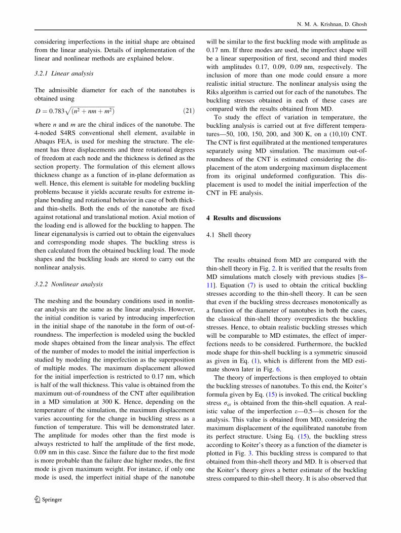
3.2.2 Nonlinear analysis
The meshing and the boundary conditions used in nonlin-
ear analysis are the same as the linear analysis. However,
the initial condition is varied by introducing imperfection
in the initial shape of the nanotube in the form of out-of-
roundness. The imperfection is modeled using the buckled
mode shapes obtained from the linear analysis. The effect
of the number of modes to model the initial imperfection is
studied by modeling the imperfection as the superposition
of multiple modes. The maximum displacement allowed
for the initial imperfection is restricted to 0.17 nm, which
is half of the wall thickness. This value is obtained from the
maximum out-of-roundness of the CNT after equilibration
in a MD simulation at 300 K. Hence, depending on the
temperature of the simulation, the maximum displacement
varies accounting for the change in buckling stress as a
function of temperature. This will be demonstrated later.
The amplitude for modes other than the first mode is
always restricted to half the amplitude of the first mode,
0.09 nm in this case. Since the failure due to the first mode
is more probable than the failure due higher modes, the first
mode is given maximum weight. For instance, if only one
mode is used, the imperfect initial shape of the nanotube
will be similar to the first buckling mode with amplitude as
0.17 nm. If three modes are used, the imperfect shape will
be a linear superposition of first, second and third modes
with amplitudes 0.17, 0.09, 0.09 nm, respectively. The
inclusion of more than one mode could ensure a more
realistic initial structure. The nonlinear analysis using the
Riks algorithm is carried out for each of the nanotubes. The
buckling stresses obtained in each of these cases are
compared with the results obtained from MD.
To study the effect of variation in temperature, the
buckling analysis is carried out at five different tempera-
tures—50, 100, 150, 200, and 300 K, on a (10,10) CNT.
The CNT is first equilibrated at the mentioned temperatures
separately using MD simulation. The maximum out-of-
roundness of the CNT is estimated considering the dis-
placement of the atom undergoing maximum displacement
from its original undeformed configuration. This dis-
placement is used to model the initial imperfection of the
CNT in FE analysis.
4 Results and discussions
4.1 Shell theory
The results obtained from MD are compared with the
thin-shell theory in Fig. 2. It is verified that the results from
MD simulations match closely with previous studies [8–
11]. Equation (7) is used to obtain the critical buckling
stresses according to the thin-shell theory. It can be seen
that even if the buckling stress decreases monotonically as
a function of the diameter of nanotubes in both the cases,
the classical thin-shell theory overpredicts the buckling
stresses. Hence, to obtain realistic buckling stresses which
will be comparable to MD estimates, the effect of imper-
fections needs to be considered. Furthermore, the buckled
mode shape for thin-shell buckling is a symmetric sinusoid
as given in Eq. (1), which is different from the MD esti-
mate shown later in Fig. 6.
The theory of imperfections is then employed to obtain
the buckling stresses of nanotubes. To this end, the Koiter’s
formula given by Eq. (15) is invoked. The critical buckling
stress rcr is obtained from the thin-shell equation. A real-
istic value of the imperfection e—0.5—is chosen for the
analysis. This value is obtained from MD, considering the
maximum displacement of the equilibrated nanotube from
its perfect structure. Using Eq. (15), the buckling stress
according to Koiter’s theory as a function of the diameter is
plotted in Fig. 3. This buckling stress is compared to that
obtained from thin-shell theory and MD. It is observed that
the Koiter’s theory gives a better estimate of the buckling
stress compared to thin-shell theory. It is also observed that
N. M. A. Krishnan, D. Ghosh
123

as the diameter of the nanotubes increases, the Koiter’s
estimate is closer to MD. But for smaller diameters, the
Koiter’s theory still overpredicts the buckling stress con-
siderably. Another drawback of the Koiter’s theory is its
inability to predict the buckled mode shape correctly.
4.2 Finite element analysis
The buckling stresses obtained using linear and nonlin-
ear FE analysis are plotted in Fig. 4. The results thus
obtained are compared with the buckling stresses obtained
from MD simulations. It is observed from Fig. 4 that the
linear analysis gives maximum estimate for the buckling
stress. This results from the fact that the linear analysis
does not take into account the variation in geometric
stiffness due to the loading. The nonlinear analysis is
carried out with an initial imperfection. The buckling
stresses obtained considering one, two, three, four and five
eigenmodes, respectively, in the initial imperfection reveal
that as the number of eigenmodes increases, the buckling
stress decreases monotonically. The buckling stresses
obtained considering three buckling modes matche well
with the buckling stress obtained using MD. In some cases,
an analysis considering four or five modes gives a mar-
ginally closer match with MD. However, the difference in
buckling stresses estimated using four and five modes are
not significantly different compared to the results obtained
from three modes. Hence, it can be inferred that the
superposition of first three buckling modes gives a realistic
initial imperfection for the nonlinear FE analysis.
Furthermore, the buckled mode shape obtained using
nonlinear FE analysis, shown in Fig. 5, is compared with
the buckled shape obtained from MD as in Fig. 6. It can be
seen that the buckled shape predicted by MD and nonlinear
FEM match well. This similarity in the failure mode vali-
dates the assumption that the inclusion of initial imper-
fection improves the estimate of both the buckling stress
and buckling shape. The FE method is computationally
much cheaper than the MD simulation. As the nanotube
size increases, MD simulation becomes more expensive
due to the force calculation involved at each time step for
each of the atoms. Hence, the proposed method for the
modeling of nanotubes considering the initial
0 0.5 1 1.5 20
1
2
3
4
5
6
7
8x 10¹¹
Radius (nm)
Buc
klin
g S
tres
s (N
/m2 )
MDShell
Fig. 2 The buckling stresses of nanotubes obtained using MD and
thin-shell theory are plotted as a function of the diameter of the
nanotubes. The thin-shell is observed to overestimate the buckling
stress of the nanotubes
0 0.5 1 1.5 20
1
2
3
4
5
6
7
8x 10¹¹
Radius (nm)
Buc
klin
g S
tres
s (N
/m2 )
MD
Shell
Koiter
Fig. 3 The buckling stresses obtained from MD, thin-shell theory and
Koiter’s theory of imperfection are plotted as a function of diameter.
It is observed that the Koiter’s theory gives a better estimate
0 0.5 1 1.5 20
0.5
1
1.5
2x 10¹¹
Radius (nm)
Buc
klin
g S
tres
s (N
/m2 )
MDLinearNL − 1 modeNL − 2 modesNL − 3 modesNL − 4 modesNL − 5 modes
Fig. 4 The buckling stresses obtained from MD and FE analysis are
plotted as a function of the tube diameter. FE analysis includes both
linear and nonlinear analysis with initial imperfection modeled as the
superposition one, two, three, four and five modes, respectively
A novel method for studying the buckling of nanotubes
123

imperfections using FE would be very useful especially for
larger nanotubes.
The effect of temperature on the prediction of buckling
stress is studied next. Three modes are considered for
modeling the out-of-roundness of the CNT as they gave a
good estimate of buckling stress. The results obtained from
the FE analysis as a function of the temperature are plotted
in Fig. 7. It is observed that the buckling stresses obtained
using FE analysis matches closely with the MD simulation
result for a range of temperatures varying from 50 to
300 K. However, as we go to even higher temperatures, the
out-of-roundness due to thermal vibrations becomes very
large. This phenomenon results in an unrealistic FE model
leading to erroneous estimation of the buckling stress.
5 Concluding remarks
This study reveals the importance of considering the
imperfections in the analysis of nanostructures, nanotubes
in particular. The imperfections in the initial shape of the
nanotube affect the buckling load and the buckling mode
shapes. It is demonstrated here that while the classical thin-
shell theory overpredicts the buckling load, Koiter’s theory
of shells with imperfection gives a better estimate. More
importantly, it is found out that the nonlinear FE analysis,
considering the imperfections in the initial structure, can be
used to explain the shell-like behavior of nanotubes
observed in MD simulations. The FE analysis predicts the
buckling load of the nanotubes accurately and is compu-
tationally cheaper compared to MD simulations by more
than an order of magnitude. The buckling mode shapes are
also predicted accurately by the nonlinear FE method.
Prediction of buckling modes would be useful to carry out
post-buckling analysis. The present method can accurately
take into account the effect of temperature in the form
Fig. 5 The mode shape of the nanotube after buckling obtained from
a nonlinear FE analysis is shown here. This is the mode shape of a
nanotube with initial imperfection as a superposition of three modes
Fig. 6 The buckled shape of a nanotube obtained from MD, with the
same diameter as that of the FE analysis, is shown. Note that the
buckled shape is very similar to that obtained from FE analysis
50 100 150 200 250 300
0.2
0.4
0.6
0.8
1
1.2
1.4
1.6
1.8
2x 10¹¹
Temperature (K)
Buc
klin
g S
tres
s (N
/m2 )
LinearNL − 1 modeNL − 2 modesNL − 3 modesMD
Fig. 7 The buckling stresses of CNTs obtained from MD and FE are
plotted as a function of temperature for (10,10) CNT. Note that NLFE
with three modes matches well with MD at different temperatures
N. M. A. Krishnan, D. Ghosh
123

initial imperfection. This ability promises a novel approach
to incorporate the effect of temperature into continuum
buckling analysis. The effectiveness and usefulness of the
present method to study post-buckling behavior need to be
further studied and understood. This method can be further
extended to study the effect of imperfections in other
behaviors such as torsional buckling, fracture.
Acknowledgements The authors would like to thank the Board of
Research in Nuclear Sciences (BRNS) grant no. 2012/36/37-BRNS/
1683 for financial support.
References
1. N. Wilson, J. Macpherson, Nat. Nanotechnol. 4, 483 (2009)
2. S.S. Wong, A.T. Woolley, T.W. Odom, J.L. Huang, P. Kim, D.V.
Vezenov, C.M. Lieber, App. Phys. Lett. 73(23), 3465 (1998)
3. H. Dai, J.H. Hafner, A.G. Rinzler, D.T. Colbert, R.E. Smalley,
Nature 384(6605), 147 (1996)
4. P. Ajayan, L. Schadler, C. Giannaris, A. Rubio, Adv. Mater.
12(10), 750 (2000)
5. A. Salehi-Khojin, N. Jalili, Compos. Sci. Technol. 68(6), 1489
(2008)
6. D. Golberg, Y. Bando, Y. Huang, T. Terao, M. Mitome, C. Tang,
C. Zhi, ACS Nano 4(6), 2979 (2010)
7. Y. Huang, J. Lin, J. Zou, M.S. Wang, K. Faerstein, C. Tang, Y.
Bando, D. Golberg, Nanoscale 5, 4840 (2013)
8. B.I. Yakobson, C.J. Brabec, J. Bernholc, Phys. Rev. Lett. 76,
2511 (1996)
9. C. Ru, J. Mech. Phys. Solids 49(6), 1265 (2001)
10. M. Buehler, Y. Kong, H. Gao, J. Eng. Mater. Technol. 126, 245
(2004)
11. J. Song, J. Wu, Y. Huang, K. Hwang, Nanotechnology 19(44),
445705 (2008)
12. C. Wang, Y. Zhang, Y. Xiang, J. Reddy, Appl. Mech. Rev. 63,
030804 (2010)
13. C.L. Zhang, H.S. Shen, Carbon 44, 2608 (2006)
14. Y. Zhang, C. Wang, V. Tan, J. Eng. Mech. ASCE 132(9), 952
(2006)
15. L. Wullschleger, H.R. Meyer-Piening, Int. J. Non-Linear Mech.
37, 645 (2002)
16. J. Peng, J. Wu, K. Hwang, J. Song, Y. Huang, J. Mech. Phys.
Solids 56(6), 2213 (2008)
17. C. Wang, Z. Tay, A. Chowdhuary, W. Duan, Y. Zhang, N. Sil-
vestre, Int. J. Struct. Stability Dyn. 6(11), 1035 (2011)
18. A. Muc, J. Th. Appl. Mech. 49(2), 531 (2011)
19. F. Tong, C. Wang, S. Adhikari, J. Appl. Phys. 105, 094325
(2009)
20. C. Li, T.W. Chou, Mech. Mater. 36, 1047 (2004)
21. B. Liu, Y. Hang, H. Jiang, S. Qu, K. Huang, Computer Methods
Appl. Mech. Eng. 193, 1849 (2005)
22. H. Wan, F. Delale, Meccanica 45, 43 (2010)
23. J. Wernik, S. Meguid, Acta Mech. 212, 167 (2010)
24. A. Sears, R. Batra, Phys. Rev. B 73, 085410 (2006)
25. W. Jiang, R. Batra, Acta Mater. 57, 4921 (2009)
26. M. Schwarzbart, A. Steindl, H. Troger, PAMM Proc. Appl. Math.
Mech. 10, 27 (2010)
27. L. Jiang, W. Guo, J. Mech. Phys. Solids 59(6), 1204 (2011)
28. S. Hollerer, Int. J. Numer. Methods Eng. 91(4), 397 (2012)
29. Q. Wang, V. Varadan, S. Quek, Phys. Lett. A 357(2), 130 (2006)
30. I. Elishakoff, Carbon Nanotubes and Nanosensors: Vibration,
Buckling and Balistic Impact (Wiley-ISTE, New York, 2013)
31. S. Timoshenko, J. Gere, Theory of Elastic Stability (McGraw-
Hill, New York, 1961)
32. Y. Zhang, C. Wang, W. Duan, Y. Xiang, Z. Zong, Nanotech-
nology 20(39), 395707 (2009)
33. D. Bushnell, AIAA J. 19(9), 1183 (1981)
34. W. Koiter, The stability of elastic equilibrium (translated by E.
Riks). Ph.D. thesis, Techische Hooge School at Delft (in Dutch)
(1945)
35. G. Simitses, Appl. Mech. Rev. 39(10), 1517 (1986)
36. J. Teng, Appl. Mech. Rev. 49(4), 263 (1996)
37. C. Schenk, G. Schueller, Int. J. Non-Linear Mech. 38(7), 1119
(2003)
38. W. Koiter, Koninklike Nederlandische Akademie van Wetens-
happen B66, 265 (1963)
39. J. Hutchinson, W. Koiter, Appl. Mech. Rev. 23(12), 1353 (1970)
40. Y. Xiaohu, H. Qiang, Compos. Sci. Technol. 67(1), 125 (2007)
41. K. Amara, A. Tounsi, I. Mechab, E.A. Adda-Bedia, Appl. Math.
Model. 34(12), 3933 (2010)
42. Y. Yan, W. Wang, L. Zhang, Appl. Math. Model. 34(11), 3422
(2010)
43. T. Murmu, S. Pradhan, Comput. Mater. Sci. 46(4), 854 (2009)
44. Y. Zhang, Y. Xiang, C. Wang, J. Appl. Phys. 106(11), 113503
(2009)
45. Q. Lu, B. Bhattacharya, Nanotechnology 16(4), 555 (2005)
46. abaqus, ABAQUS/CAE user’s manual: version 6.4. (ABAQUS,
Pawtucket, 2003)
47. W. Humphrey, A. Dalke, K. Schulten, J. Mol. Grap. 14, 33 (1996)
48. S. Plimpton, J. Comp. Phys. 117, 1 (1995). http://lammps.sandia.
gov
49. S.J. Stuart, A.B. Tutein, J.A. Harrison, J. Chem. Phys. 112(14),
6472 (2000)
50. D.W. Brenner, O.A. Shenderova, J.A. Harrison, S.J. Stuart, B. Ni,
S.B. Sinnott, J. Phys, Cond. Matter 14(4), 783 (2002)
51. J.P. Lu, Phys. Rev. Lett. 79, 1297 (1997)
52. E. Hernandez, C. Goze, P. Bernier, A. Rubio, Phys. Rev. Lett. 80,
4502 (1998)
A novel method for studying the buckling of nanotubes
123