Embed Size (px)
Citation preview
www.ijatir.org
ISSN 2348–2370
Vol.08,Issue.07,
July-2016,
Pages:1402-1407
Copyright @ 2016 IJATIR. All rights reserved.
A Novel Harmonics Elimination Method for Three -Phase Industrial Applications V. KEERTHI
1, S. M. ZAFARULLAH
2
1PG Scholar, Dept of EEE, Vidya Jyothi Institute of Technology, India.
2Assistant Professor, Dept of EEE, Vidya Jyothi Institute of Technology, India.
Abstract: There are many ongoing researches in the field of
harmonic compensation using active and passive power filters
or the combination of the two, which are known as hybrid
power filters. These filters can be implemented as series or
shunt units. For shunt compensation, the voltage rating of the
components is usually higher, and the impedance of the
filtering unit should be very high to block the flow of the
fundamental harmonic. For the series compensation, the
impedance for the fundamental components should be
minimal. In order to improve the power quality, many control
algorithms have been proposed for automatic and selective
harmonic compensation. In this project to ensuring power
quality both in the grid current and PCC by harmonic
elimination is presented. The proposed method is developed to
take care of harmonics in grid-connected (GC) mode, as well
as in the islanded or standalone (SA) mode of operation,
where the main objective is to remove the harmonics from the
grid current and the point of common coupling (PCC) voltage.
The suggested placement of the harmonic reduction unit
dictates the use of a special controller structure that uses the
harmonics magnitude in the dq reference frame. In the
proposed control algorithm, the required amount of
attenuation for harmonics is determined to meet the total
harmonic distortion. Fast and efficient algorithm for phase
detection irrespective of the presence of harmonics has been
utilized for the system. The effectiveness of proposed method
is verified by using Matlab/Simulink software.
Keywords: Adaptive Compensation, Distributed Renewable
Energy Sources, Grid-Connected Microgrid, Harmonics,
Power Quality, Standalone Microgrid.
I. INTRODUCTION
Electrical power demand within a micro grid power system
requires reliable functionality, storage of energy, diagnostics,
remote device control and monitoring as important functions
of modern Distributed Power Generation (DPG) modules.
Renewable energy sources like solar, wind, and micro-
hydropower can be interfaced through the DPG modules with
the microgrid system which can operate in islanded mode
(off-grid) and gridconnected mode. The microgrid operation
needs to respond to the load demand under any circumstances
therefore back-up with energy storage elements is essential.
The microgrid presented in this paper is a low voltage
application and it is comprised of DPG modules, distributed
energy storage elements, electrical distribution gear and
controllable loads. DPG modules are critical components
within the microgrid systems and need to have flexible
features in order to respond for a wide range of
applications. DPG are designed to operate in islanded
mode, utility grid-connected or genset-connected (diesel,
liquid propane generators). DPG converter modules may
have the following modes of operation: voltage-controlled
source, current controlled source, active rectifier and active
power filter mode. The converted energy produced can be
delivered to the local loads within the micro grid structure
or exported to the utility grid. In active rectifier mode, with
ac to dc energy conversion the DG has a multi loop
embedded control with power factor correction and dc
voltage and current are controlled typically for battery
charging [1].
In active power filter mode selective ac current
harmonics are generated to cancel out the load current
harmonics from the fundamental line frequency [2]. PV
inverters are typically DPG operating in current controlled
mode, with dc to ac energy conversion where ac current is
controlled in magnitude and phase [3], [4]. Transformerless
PV inverters represent an attractive solution due to higher
efficiency, smaller size and weight, reduced cost [5], [6].
In many industrial applications, usually, DC motors were
the work horses for the regulating Speed Drives [7] (ASDs)
because of their excellent speed and torque response. But,
they have inherent disadvantage of commutator and
mechanical brushes, which go through wear and tear with
the passage of time. Generally [9], AC motors are preferred
to DC motors, in particular, an induction motor because to
its low cost, low maintenance, lower weight, low
maintenance, higher efficiency, improved ruggedness and
reliability. All these features make the use of induction
motors a mandatory in many areas of industrial
applications. The improvement in Power electronics [10]
and semi-conductor technology has triggered the growth of
high power and high speed semiconductor devices in order
to get a smooth, continuous and step less variation in motor
speed.
Applications of solid state converters/inverters for
adjustable speed induction motor drive are well-known in
electromechanical systems for a large spectrum of
industrial systems. Comparison of basic and high
frequency carrier based techniques for NPC inverters is
V. KEERTHI, S. M. ZAFARULLAH
International Journal of Advanced Technology and Innovative Research
Volume. 08, IssueNo.07, July-2016, Pages: 1402-1407
given by Feng, 2000. Influence of number of stator windings
on the characteristics of motor is given by Golubev, 2000.
Modified CSI based induction motor drive is given by
Gopukumar, 1984. Multilevel inverter modulation schemes to
eliminate common mode voltage is given by Zhang, 2000.
Modulation schemes for six phase induction motor are given
by Mohapatra, 2002. Improved reliability in solid state ac
drives is given by Thomas, 1980. Multilevel converters [11]
for large electric drives are given by Peng, 1999. Active
harmonic elimination for multilevel inverters is given by
Tolbert, 2006. The inverters are either Current Source Inverter
(CSIs) or Voltage [8] Source Inverters (VSIs). Current source
inverters are widely used for the implementation of fully
generative induction machine variable speed drives. An
important and attractive feature of CSI is its good fault
protection capability and the inherent regeneration capability.
II. PLACEMENT OF HARMONIC COMPENSATION
UNIT IN MICROGRID SYSTEM
In conventional methods [13], [14], the series harmonics
reduction units are placed at the grid side, as shown in Fig.1
where the objective is to make the line impedance at the
harmonic frequency as high as possible. From Fig.1,
Fig.1.Conventional harmonic compensation method.
The mesh equations for the overall system for harmonic
components can be written as follows:
(1)
(2)
WhereVnpcc ,Vninj , In1Znc1 represents the nth harmonic PCC
voltage, injected voltage, grid current, and coupling
impedance, respectively. The grid current can be expressed as
(3)
The injected harmonic voltage in series with the grid is
proportional to the grid current such as
(4)
Where gain of knis related to the coupling impedance and the
transformer turns ratio. Based on (1) and (4), In1can be
determined as
(5)
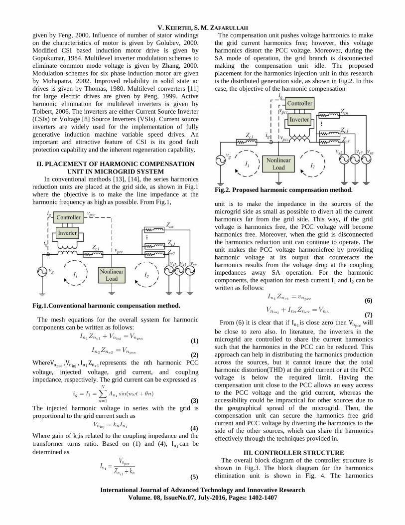
The compensation unit pushes voltage harmonics to make
the grid current harmonics free; however, this voltage
harmonics distort the PCC voltage. Moreover, during the
SA mode of operation, the grid branch is disconnected
making the compensation unit idle. The proposed
placement for the harmonics injection unit in this research
is the distributed generation side, as shown in Fig.2. In this
case, the objective of the harmonic compensation
Fig.2. Proposed harmonic compensation method.
unit is to make the impedance in the sources of the
microgrid side as small as possible to divert all the current
harmonics far from the grid side. This way, if the grid
voltage is harmonics free, the PCC voltage will become
harmonics free. Moreover, when the grid is disconnected
the harmonics reduction unit can continue to operate. The
unit makes the PCC voltage harmonicfree by providing
harmonic voltage at its output that counteracts the
harmonics results from the voltage drop at the coupling
impedances away SA operation. For the harmonic
components, the equation for mesh current I1 and I2 can be
written as follows:
(6)
(7)
From (6) it is clear that if In1 is close zero then Vnpcc will
be close to zero also. In literature, the inverters in the
microgrid are controlled to share the current harmonics
such that the harmonics in the PCC can be reduced. This
approach can help in distributing the harmonics production
across the sources, but it cannot insure that the total
harmonic distortion(THD) at the grid current or at the PCC
voltage is below the required limit. Having the
compensation unit close to the PCC allows an easy access
to the PCC voltage and the grid current, whereas the
accessibility could be impractical for other sources due to
the geographical spread of the microgrid. Then, the
compensation unit can secure the harmonics free grid
current and PCC voltage by diverting the harmonics to the
side of the other sources, which can share the harmonics
effectively through the techniques provided in.
III. CONTROLLER STRUCTURE
The overall block diagram of the controller structure is
shown in Fig.3. The block diagram for the harmonics
elimination unit is shown in Fig. 4. The harmonics
A Novel Harmonics Elimination Method for Three -Phase Industrial Applications
International Journal of Advanced Technology and Innovative Research
Volume. 08, IssueNo.07, July-2016, Pages: 1402-1407
elimination unit mainly consists of two major blocks—
harmonics estimation block and harmonics injection block.
Efficient and effective harmonics estimation and the
harmonics elimination methods, suggested and illustrated in
Fig. 4, are used for phase detection and harmonics component
estimation. As the existence of the harmonics affect the PLL
accuracy, the first stage is used to eliminate the harmonics
from the sampled grid signal ensuring accuracy of the PLL.
The second stage provides fast and accurate harmonics
estimation as the PLL produces an accurate phase. The
harmonics injection block, which dictates the amount of
harmonics injection by the harmonics compensator.
Fig.3. Overall, harmonic compensation block.
Fig.4. Harmonics elimination block diagram.
The grid current and/or the PCC voltage are fed to the phase
locked look (PLL) block. The PLL lock extracts the phase of
the fundamental component. Then, using the PLL output,the
3rd
, 5th
. . . nth
harmonics of these signals are estimated. The dq
components of the estimated harmonics are sent to the
harmonics injection block to determine how much voltage at
the specified harmonic frequency should be injected into the
line based on the error between the actual and reference.
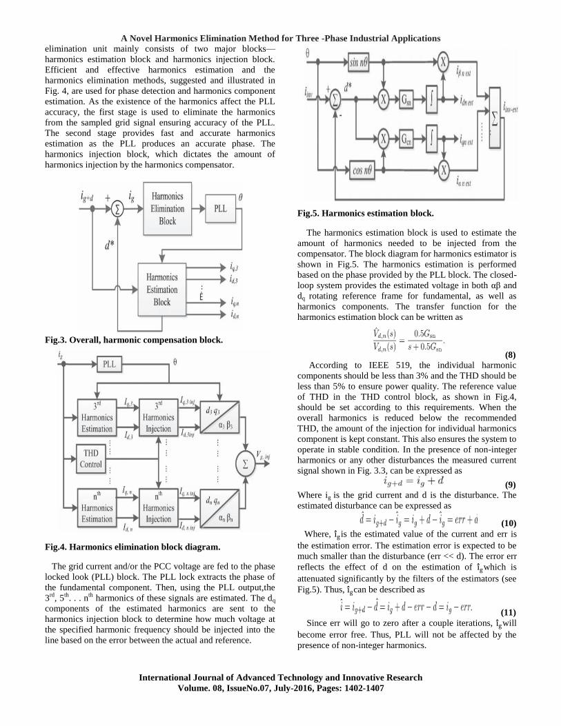
Fig.5. Harmonics estimation block.
The harmonics estimation block is used to estimate the
amount of harmonics needed to be injected from the
compensator. The block diagram for harmonics estimator is
shown in Fig.5. The harmonics estimation is performed
based on the phase provided by the PLL block. The closed-
loop system provides the estimated voltage in both αβ and
dq rotating reference frame for fundamental, as well as
harmonics components. The transfer function for the
harmonics estimation block can be written as
(8) According to IEEE 519, the individual harmonic
components should be less than 3% and the THD should be
less than 5% to ensure power quality. The reference value
of THD in the THD control block, as shown in Fig.4,
should be set according to this requirements. When the
overall harmonics is reduced below the recommended
THD, the amount of the injection for individual harmonics
component is kept constant. This also ensures the system to
operate in stable condition. In the presence of non-integer
harmonics or any other disturbances the measured current
signal shown in Fig. 3.3, can be expressed as
(9)
Where ig is the grid current and d is the disturbance. The
estimated disturbance can be expressed as
(10)
Where, i g is the estimated value of the current and err is
the estimation error. The estimation error is expected to be
much smaller than the disturbance (err << d). The error err
reflects the effect of d on the estimation of i gwhich is
attenuated significantly by the filters of the estimators (see
Fig.5). Thus, i gcan be described as
(11)
Since err will go to zero after a couple iterations, i gwill
become error free. Thus, PLL will not be affected by the
presence of non-integer harmonics.
V. KEERTHI, S. M. ZAFARULLAH
International Journal of Advanced Technology and Innovative Research
Volume. 08, IssueNo.07, July-2016, Pages: 1402-1407
Fig.6. Harmonics injection unit.
IV.CONTROLLER OPERATION
Fig.5 illustrates the block diagram of the harmonics
injection unit, where the desired amounts of harmonics are
commanded in dq reference frame. Desired THD level is also
provided as a reference into the controller block. The THD
control block receives the commanded THD and actual THD
of the grid current or voltage at PCC. The THD reference is
usually set according to the required power quality. The d and
q component of the harmonic current or voltage should be
reduced to eliminate harmonics from the system. This scheme
ensures that in the absence of any particular harmonics, the
compensation unit will not inject any extra harmonics to the
system (see Fig.6). The PI controller is responsible for
reducing the harmonics components below the specified limit.
After the THD level reaches below the allowable limit, the PI
controller output stabilizes and continues to inject the
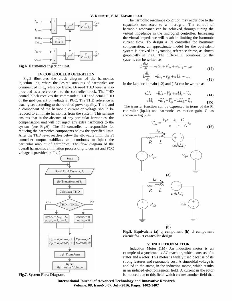
particular amount of harmonics. The flow diagram of the
overall harmonics elimination process of grid current and PCC
voltage is provided in Fig.7.
Fig.7. System Flow Diagram.
The harmonic resonance condition may occur due to the
capacitors connected to a microgrid. The control of
harmonic resonance can be achieved through tuning the
virtual impedance in the microgrid controller. Increasing
the virtual impedance will result in limiting the harmonic
current flow. To design a PI controller for harmonic
compensation, an approximate model for the equivalent
system is derived in dq rotating reference frame, as shown
graphically in Fig.8. The differential equations for the
systems can be written as
(12)
(13)
In the Laplace domain (12) and (13) can be written as
(14)
(15)
The transfer function can be expressed in terms of the PI
controller (kp,ki) and harmonics estimation gain, G, as
shown in Fig.5, as
(16)
(a)
(b)
Fig.8. Equivalent (a) q component (b) d component
circuit for PI controller design.
V. INDUCTION MOTOR
Induction Motor (1M) An induction motor is an
example of asynchronous AC machine, which consists of a
stator and a rotor. This motor is widely used because of its
strong features and reasonable cost. A sinusoidal voltage is
applied to the stator, in the induction motor, which results
in an induced electromagnetic field. A current in the rotor
is induced due to this field, which creates another field that
A Novel Harmonics Elimination Method for Three -Phase Industrial Applications
International Journal of Advanced Technology and Innovative Research
Volume. 08, IssueNo.07, July-2016, Pages: 1402-1407
tries to align with the stator field, causing the rotor to spin. A
slip is created between these fields, when a load is applied to
the motor. Compared to the synchronous speed, the rotor
speed decreases, at higher slip values. The frequency of the
stator voltage controls the synchronous speed [12]. The
frequency of the voltage is applied to the stator through power
electronic devices, which allows the control of the speed of
the motor. The research is using techniques, which implement
a constant voltage to frequency ratio. Finally, the torque
begins to fall when the motor reaches the synchronous speed.
Thus, induction motor synchronous speed is defined by
following equation,
(17)
Where f is the frequency of AC supply, n, is the speed of
rotor; p is the number of poles per phase of the motor. By
varying the frequency of control circuit through AC supply,
the rotor speed will change as shown in Fig.9.
Fig.9.Speed torque characteristics of induction motor.
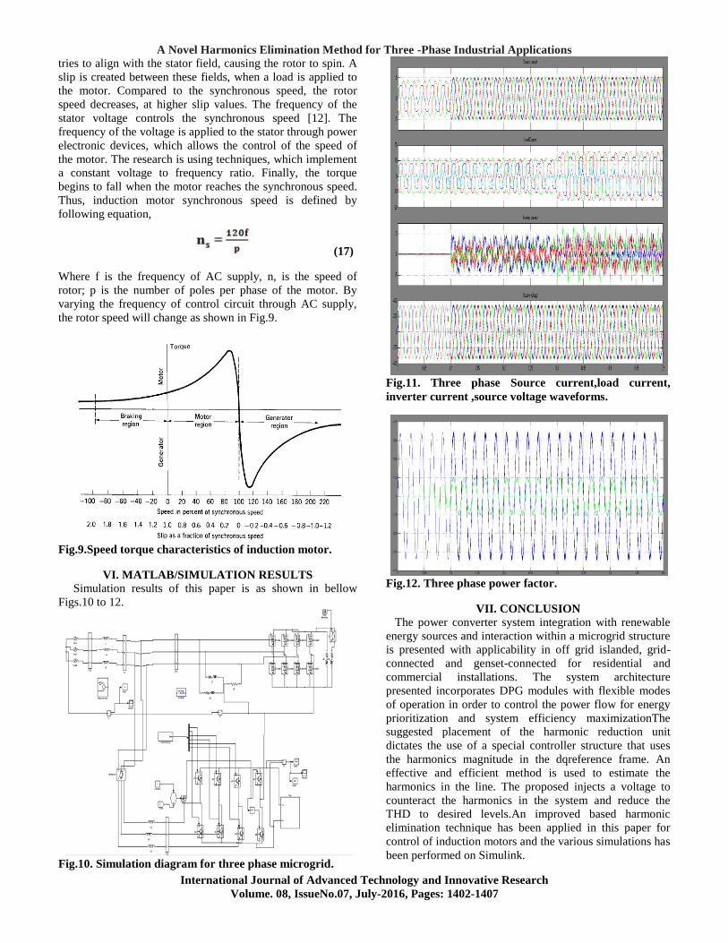
VI. MATLAB/SIMULATION RESULTS
Simulation results of this paper is as shown in bellow
Figs.10 to 12.
Fig.10. Simulation diagram for three phase microgrid.
Fig.11. Three phase Source current,load current,
inverter current ,source voltage waveforms.
Fig.12. Three phase power factor.
VII. CONCLUSION
The power converter system integration with renewable
energy sources and interaction within a microgrid structure
is presented with applicability in off grid islanded, grid-
connected and genset-connected for residential and
commercial installations. The system architecture
presented incorporates DPG modules with flexible modes
of operation in order to control the power flow for energy
prioritization and system efficiency maximizationThe
suggested placement of the harmonic reduction unit
dictates the use of a special controller structure that uses
the harmonics magnitude in the dqreference frame. An
effective and efficient method is used to estimate the
harmonics in the line. The proposed injects a voltage to
counteract the harmonics in the system and reduce the
THD to desired levels.An improved based harmonic
elimination technique has been applied in this paper for
control of induction motors and the various simulations has
been performed on Simulink.
V. KEERTHI, S. M. ZAFARULLAH
International Journal of Advanced Technology and Innovative Research
Volume. 08, IssueNo.07, July-2016, Pages: 1402-1407
VIII. REFERENCES
[1].Saeed Anwar, Ali Elrayyah, and Yilmaz Sozer, Senior
Member, IEEE‖Efficient Single-Phase Harmonics Elimination
Method for Microgrid Operations‖IEEE Transactions On
Industry Applications, Vol. 51, No. 4, July/August 2015
[2] R. Erickson and D. Maksimovic, ―Fundamentals of
PowerElectronics,‖ 2nd Ed., Springer Science+Business,
2001, Ch.18.
[3] C. Lascu, L. Asiminoaei, I. Boldea, and F. Blaabjerg,
―Frequency Response Analysis of Current Controllers for
Selective Harmonic Compensation in Active Power Filters,‖
IEEE Trans. Power Electron., vol. 56, no. 2, pp. 1826–1835,
Feb. 2009.
[4] F. Blaabjerg, R. Teodorescu, M. Liserre, A.
Timbus,‖Overview of Control and Grid Synchronization for
Distributed Power Generation Systems,‖ IEEE Trans. Ind.
Electron., vol. 53, pp. 1398-1409, Oct. 2006.
[5] M. Brenna, G.C. Lazaroiu, G. Superti-Furga, and E.
Tironi, ―Bidirectional Front End Converter for DG With
Disturbance Insensitivity and Islanding-Detection Capability,―
IEEE Trans. Power Delivery, vol. 23, no. 2, pp. 907-914,
April 2008.
[6] T. Kerekes, R. Teodorescu and U. Borup, ―Transformer
less Photovoltaic Inverters Connected to the Grid,‖ in Applied
Power Electronics Conf., APEC 2007 - Twenty Second
Annual IEEE, pp. 1733 – 1737, Feb. 2007-March 2007.
[7] M. Dai, M. Marwali, J. Jung, and A. Keyhani, ―Power
flow control of a single distributed generation unit,‖ IEEE
Trans. Power Electron., vol. 23, no. 1, pp. 343–352, Jan. 2008.
[8] D. Ben Attous and Y. Bekakra, ―Speed Control of a
Doubly Fed Induction Motor using Fuzzy Logic Techniques‖,
International Journal of Electrical Engineering and
Informatics, Vol. 2, No. 3, December 2010.
[9] M. D. Manjrekar, P. K. Steimer, and T. A. Lipo, ―Hybrid
multilevel power conversion system: a competitive solution
for high-power applications,‖ IEEE Transactions on Industry
Applications, vol. 36, pp. 834–841, May/June 2000
[10] Kennedy, James. "Particle swarm optimization."
Encyclopedia of Machine Learning. Springer US, 2010. 760-
766.
[11] Moradi, M. H., and M. Abedini. "A combination of
genetic algorithm and particle swarm optimization for optimal
DG location and sizing in distribution systems." International
Journal of Electrical Power &Energy Systems 34.1 (2012):
66-74.
[12] Gandomi, Amir Hossein, et al. "Chaos-enhanced
accelerated particle swarm optimization." Communications in
Nonlinear Science and Numerical Simulation 18.2 (2013):
327-340.
[13] X. Yu and A. M. Khambadkone, ―Combined active and
reactive power control of power converter building block to
facilitate the connection of micro-grid to Electric Power
system,‖ in Proc. IEEE ECCE, 2009, pp. 1444–1450.
[14] M. Rahmatian, M. J. Sanjari, M. Gholami, and G. B.
Gharehpetian, ―Optimal control of distribution line series
compensator in micro grid considering fault current limitation
function,‖ in Proc. 17th Conf. EPDC, May 2012, pp. 1–5.
Author’s Profile:
Prof S.M.Zafarullah received his B.Tech,
M.Tech degrees and pursuing his Ph.D
from the College of Engineering,
Jawaharlal Nehru Technological University,
and Hyderabad. Currently he is working as
Head of the Department of Electrical and
Electronics Engineering at VidyaJyothi Institute of
Technology, Aziz Nagar Gate, C.B. Post, Hyderabad-75;
He published numerous papers on Power systems and
FACTS. His current research interests include Energy
Management, Power transmission, Diagnostic Testing,
Insulation, Electromagnetic fields.
V.Keerthi was born in India in 1992. She
received her bachelor’s degree from JBIT
from Jawaharlal Nehru Technology
University Hyderabad, Telanagna on 2014.
She is currently pursuing Master in
Technology in Power Electronics &
Electrical Drives (PEED) from VidyaJyothi Institute of
Technology, Aziz Nagar Gate, C.B. Post, and Hyderabad-
75 from the same university.