Embed Size (px)
Citation preview

8/6/2019 A Novel Design of a Cpw-fed Single Square-loop
http://slidepdf.com/reader/full/a-novel-design-of-a-cpw-fed-single-square-loop 1/6
Journal of the Chinese Institute of Engineers, Vol. 31, No. 6, pp. xx-xx (2008) 1
A NOVEL DESIGN OF A CPW-FED SINGLE SQUARE-LOOP
ANTENNA FOR CIRCULAR POLARIZATION
I-Chung Deng*, Ren-Jie Lin, Qing-Xiang Ke, Jia-Min Huang and Kow-Ming Chang
ABSTRACT
The experimental and simulated results for the proposed antenna are investi-
gated in this article. Moreover, a novel broadband design of a circularly polarized
(CP) single square slot antenna fed by a single coplanar waveguide is presented. By
appropriately choosing the circumference of the square-loop, the length of the pro-
truded strip, and the gap, this proposed antenna thus owns good CP radiation andgood impedance match simultaneously at the frequency of 2.45 GHz. This proposed
antenna has the fundamental resonant frequency of 2.5 GHz with the minimum return
loss of -39.9 dB. Furthermore, its impedance bandwidth is 460 MHz or 18.4% and
3-dB axial-ratio (AR) bandwidth is 360 MHz or 14.4% at 2.5 GHz.
Key Words: circularly polarized, square slot antenna, coplanar waveguide, axial ratio.
*Corresponding author. (Tel: 886-2-28927154 ext. 8408; Fax:
886-2-2892064; Email: [email protected])
I. C. Deng, Q. X. Ke and J. M. Huang are with the Department
of Electronics Engineering and Ins t i tute of Mechatronic
Engineering, Technology and Science Institute of Northern Taiwan,
Taipei, Taiwan 112, R.O.C.
K. M. Chang is with the Department of Electronics Engineering
and Institute of Electronics, National Chiao Tung University,Hsinchu, Taiwan 30050, R.O.C.
I. INTRODUCTION
Advantageously, circularly polarized (CP) an-tennas radiate nearly constant radiation even though
the angle of the antenna changes. Recently, the sig-
nal-feed coplanar waveguide (CPW) antenna for pro-
ducing CP radiation with a compact antenna size has
received much attention. CPW antennas are prefer-
able for monolithic microwave integrated circuits
(MMIC) since no backside processing is required for
integrating with devices (Kormanyos et al., 1994).
In order to obtain circularly polarized (CP) radiation
by a single feed, many microstrip antenna designs have
been reported (Wong, 2002). However, the CP band-
width of the conventional microstrip antenna deter-
mined by 3-dB axial-ratio (AR) is usually narrow andsometimes even less than 2%. From previous works,
Wong et al. (2002) have proposed microstrip-line-fed
ring slot antennas with 3-dB AR bandwidths of only
about 4.3% and 3.5% for square and annular ring slot
antennas, respectively. Although a few CP slot an-
tennas have been designed for CPW-feed, the sizes
of these antennas are over 70 × 70 mm2 (Sze et al.,
2003; Chen et al., 2006). In this paper, a compact
CPW-fed square slot antenna with the size of 42 × 51
mm2 is designed. In order to generate a CP wave, the
square-loop is slit into two arms through a narrow
gap. Furthermore, the length of the two arms can be
used to adjust two standing-wave currents. The CP
wave is radiated when two standing-wave current dis-
tributions are at equal amplitude and at quarter-wave
length difference (Lin et al., 2005; Elliott, 2003). This
new slot antenna resembles the presented antenna
geometry of these literatures (Morishita et al., 1998;
shi et al., 2001; Chang et al., 2006) which include
two rhombic or rectangular loop wire antennas.Frankly speaking, the presented antennas in these
papers have several disadvantages such as larger
structure, more difficult fabrication, and narrower AR
bandwidth than our proposed ones. Our proposed an-
tenna excludes these drawbacks and shows better cir-
cularly polarized radiation performance.
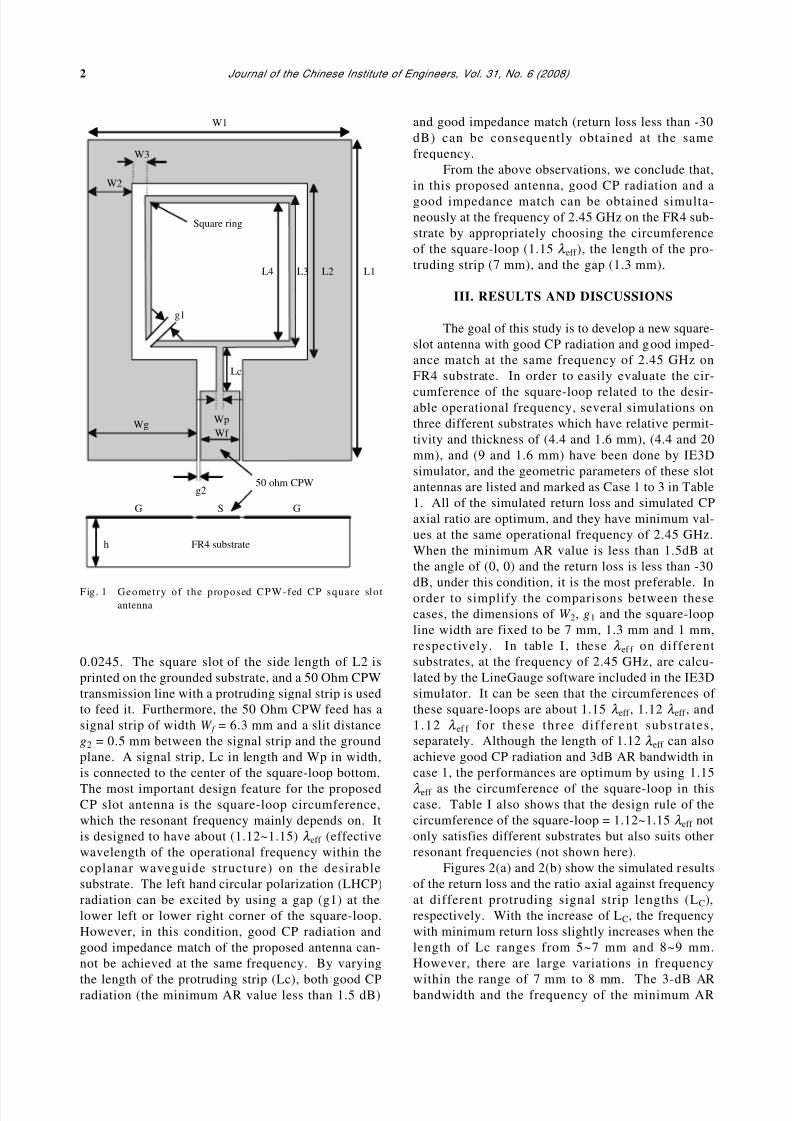
II. ANTENNA CONFIGURATIONS
The geometry of the proposed antenna is shown
in Fig. 1. It is realized on an inexpensive FR4 di-
electric material with a thickness (h) of 1.6 mm, arelative permittivity (ε r ) of 4.4, and a loss tangent of
ARTICLE IN PRESS
8/6/2019 A Novel Design of a Cpw-fed Single Square-loop
http://slidepdf.com/reader/full/a-novel-design-of-a-cpw-fed-single-square-loop 2/6
2 Journal of the Chinese Institute of Engineers, Vol. 31, No. 6 (2008)
0.0245. The square slot of the side length of L2 is
printed on the grounded substrate, and a 50 Ohm CPW
transmission line with a protruding signal strip is used
to feed it. Furthermore, the 50 Ohm CPW feed has a
signal strip of width W f = 6.3 mm and a slit distance
g2 = 0.5 mm between the signal strip and the ground
plane. A signal strip, Lc in length and Wp in width,
is connected to the center of the square-loop bottom.
The most important design feature for the proposedCP slot antenna is the square-loop circumference,
which the resonant frequency mainly depends on. It
is designed to have about (1.12~1.15) λ eff (effective
wavelength of the operational frequency within the
coplanar waveguide structure) on the desirable
substrate. The left hand circular polarization (LHCP)
radiation can be excited by using a gap (g1) at the
lower left or lower right corner of the square-loop.
However, in this condition, good CP radiation and
good impedance match of the proposed antenna can-
not be achieved at the same frequency. By varying
the length of the protruding strip (Lc), both good CPradiation (the minimum AR value less than 1.5 dB)
and good impedance match (return loss less than -30
dB) can be consequently obtained at the same
frequency.
From the above observations, we conclude that,
in this proposed antenna, good CP radiation and a
good impedance match can be obtained simulta-
neously at the frequency of 2.45 GHz on the FR4 sub-
strate by appropriately choosing the circumference
of the square-loop (1.15 λ eff ), the length of the pro-
truding strip (7 mm), and the gap (1.3 mm).
III. RESULTS AND DISCUSSIONS
The goal of this study is to develop a new square-
slot antenna with good CP radiation and good imped-
ance match at the same frequency of 2.45 GHz on
FR4 substrate. In order to easily evaluate the cir-
cumference of the square-loop related to the desir-able operational frequency, several simulations on
three different substrates which have relative permit-
tivity and thickness of (4.4 and 1.6 mm), (4.4 and 20
mm), and (9 and 1.6 mm) have been done by IE3D
simulator, and the geometric parameters of these slot
antennas are listed and marked as Case 1 to 3 in Table
1. All of the simulated return loss and simulated CP
axial ratio are optimum, and they have minimum val-
ues at the same operational frequency of 2.45 GHz.
When the minimum AR value is less than 1.5dB at
the angle of (0, 0) and the return loss is less than -30
dB, under this condition, it is the most preferable. In
order to simplify the comparisons between these
cases, the dimensions of W 2, g1 and the square-loop
line width are fixed to be 7 mm, 1.3 mm and 1 mm,
respectively. In table I, these λ ef f on different
substrates, at the frequency of 2.45 GHz, are calcu-
lated by the LineGauge software included in the IE3D
simulator. It can be seen that the circumferences of
these square-loops are about 1.15 λ eff , 1.12 λ eff , and
1.12 λ ef f for these three different substrates ,
separately. Although the length of 1.12 λ eff can also
achieve good CP radiation and 3dB AR bandwidth in
case 1, the performances are optimum by using 1.15
λ eff as the circumference of the square-loop in thiscase. Table I also shows that the design rule of the
circumference of the square-loop = 1.12~1.15 λ eff not
only satisfies different substrates but also suits other
resonant frequencies (not shown here).
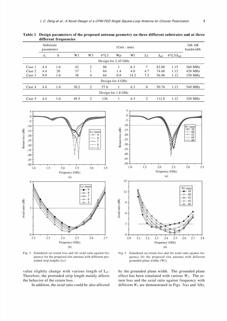
Figures 2(a) and 2(b) show the simulated results
of the return loss and the ratio axial against frequency
at different protruding signal strip lengths (LC),
respectively. With the increase of LC, the frequency
with minimum return loss slightly increases when the
length of Lc ranges from 5~7 mm and 8~9 mm.
However, there are large variations in frequency
within the range of 7 mm to 8 mm. The 3-dB ARbandwidth and the frequency of the minimum AR
W1
W3
W2
L3L4
Lc
WgWf
Wp
g2
G S
FR4 substrateh
G
g1
Square ring
50 ohm CPW
L2 L1
Fig. 1 Geometry of the proposed CPW-fed CP square slotantenna
8/6/2019 A Novel Design of a Cpw-fed Single Square-loop
http://slidepdf.com/reader/full/a-novel-design-of-a-cpw-fed-single-square-loop 3/6
I. C. Deng et al.: A Novel Design of a CPW-FED Single Square-Loop Antenna for Circular Polarization 3
value slightly change with various length of LC.
Therefore, the protruded strip length mainly affects
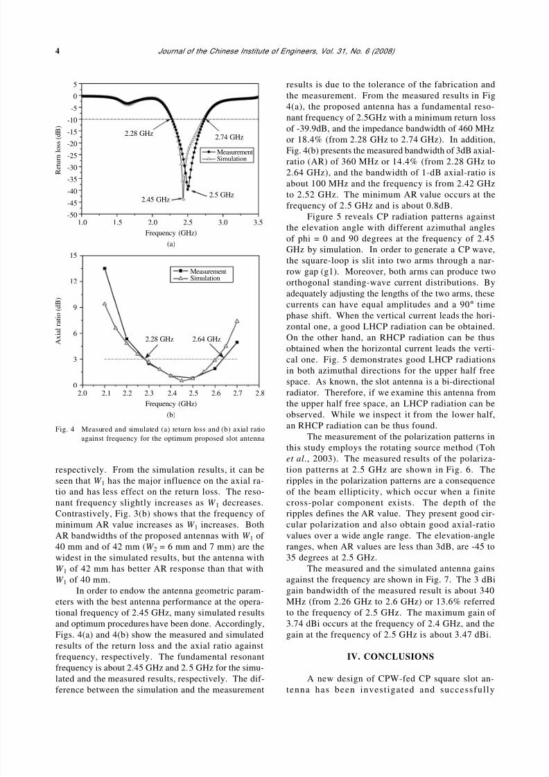
the behavior of the return loss.In addition, the axial ratio could be also affected
by the grounded plane width. The grounded plane
effect has been simulated with various W 1. The re-
turn loss and the axial ratio against frequency withdifferent W 1 are demonstrated in Figs. 3(a) and 3(b),
Table 1 Design parameters of the proposed antenna geometry on three different substrates and at three
different frequencies
Substrate 3db AR(Unit : mm)
parameters bandwidth
ε r h W1 W3 4*L3 Wp Wf Lc λ eff 4*L3/ λ eff
Design for 2.45 GHz
Case 1 4.4 1.6 42 2 96 1 6.3 7 82.88 1.15 360 MHz
Case 2 4.4 20 37 1 84 1.4 4.0 4.7 74.68 1.12 420 MHz
Case 3 9.0 1.6 38 4 64 0.8 14.2 7.5 56.96 1.12 150 MHz
Design for 4 GHz
Case 4 4.4 1.6 30.2 2 57.6 1 6.3 6 50.76 1.13 540 MHz
Design for 1.8 GHz
Case 5 4.4 1.6 49.5 2 126 1 6.3 2 112.8 1.12 320 MHz
50
-5
-10
-15
-20
-25
-30
-35
-40
-45
-50
1.0 1.5 2.0 2.5Frequency (GHz)
(a)
3.0 3.5
R e t u r n l o s s ( d B )
Lc (mm)98765
6
3
02.2 2.3 2.4 2.5
Frequency (GHz)
(b)
2.6 2.7
A x i a l r a t i o ( d B )
Lc (mm)98765
Fig. 2 Simulated (a) return loss and (b) axial ratio against fre-
quency for the proposed slot antenna with different pro-
truded strip lengths (Lc)
5
0
-5
-10
-15
-20
-25
-30
-35
-40
-45
-50
1.0 1.5 2.0 2.5
Frequency (GHz)
(a)
3.0 3.5
R e t u r n l o s s ( d B ) W1 (mm)
3840424446
W1 (mm)3840424446
15
12
9
6
3
0
2.0 2.1 2.2 2.3 2.4 2.5
Frequency (GHz)
(b)
2.72.6 2.8
A x i a l r a t i o ( d B )
Fig. 3 Simulated (a) return loss and (b) axial ratio against fre-
quency for the proposed slot antenna with different
grounded plane widths (W1)
8/6/2019 A Novel Design of a Cpw-fed Single Square-loop
http://slidepdf.com/reader/full/a-novel-design-of-a-cpw-fed-single-square-loop 4/6
4 Journal of the Chinese Institute of Engineers, Vol. 31, No. 6 (2008)
respectively. From the simulation results, it can be
seen that W 1 has the major influence on the axial ra-
tio and has less effect on the return loss. The reso-
nant frequency slightly increases as W 1 decreases.
Contrastively, Fig. 3(b) shows that the frequency of
minimum AR value increases as W 1 increases. Both
AR bandwidths of the proposed antennas with W 1 of
40 mm and of 42 mm (W 2 = 6 mm and 7 mm) are thewidest in the simulated results, but the antenna with
W 1 of 42 mm has better AR response than that with
W 1 of 40 mm.
In order to endow the antenna geometric param-
eters with the best antenna performance at the opera-
tional frequency of 2.45 GHz, many simulated results
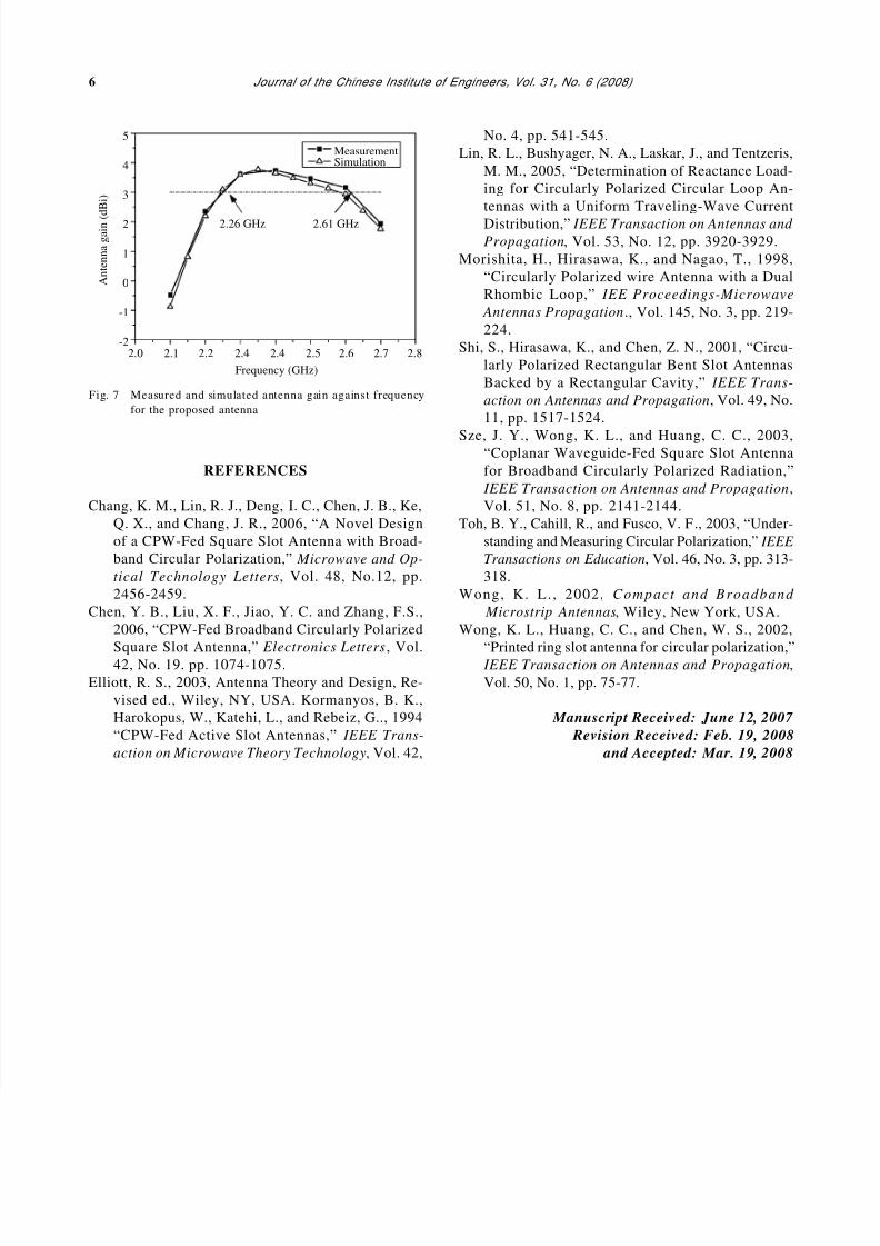
and optimum procedures have been done. Accordingly,
Figs. 4(a) and 4(b) show the measured and simulated
results of the return loss and the axial ratio against
frequency, respectively. The fundamental resonant
frequency is about 2.45 GHz and 2.5 GHz for the simu-
lated and the measured results, respectively. The dif-ference between the simulation and the measurement
5
0
-5
-10
-15
-20
-25
-30
-35
-40
-45
-501.0 1.5 2.0
2.28 GHz
2.45 GHz2.5 GHz
2.74 GHz
2.5
Frequency (GHz)
(a)
3.0 3.5
R e t u r n l o s s ( d
B )
MeasurementSimulation
15
12
9
6
3
02.0 2.1 2.2 2.3 2.4
2.64 GHz2.28 GHz
2.5
Frequency (GHz)
(b)
2.6 2.7 2.8
A x i a l r a t i o ( d B )
MeasurementSimulation
Fig. 4 Measured and simulated (a) return loss and (b) axial ratio
against frequency for the optimum proposed slot antenna
results is due to the tolerance of the fabrication and
the measurement. From the measured results in Fig
4(a), the proposed antenna has a fundamental reso-
nant frequency of 2.5GHz with a minimum return loss
of -39.9dB, and the impedance bandwidth of 460 MHz
or 18.4% (from 2.28 GHz to 2.74 GHz). In addition,
Fig. 4(b) presents the measured bandwidth of 3dB axial-
ratio (AR) of 360 MHz or 14.4% (from 2.28 GHz to
2.64 GHz), and the bandwidth of 1-dB axial-ratio is
about 100 MHz and the frequency is from 2.42 GHz
to 2.52 GHz. The minimum AR value occurs at the
frequency of 2.5 GHz and is about 0.8dB.
Figure 5 reveals CP radiation patterns against
the elevation angle with different azimuthal angles
of phi = 0 and 90 degrees at the frequency of 2.45
GHz by simulation. In order to generate a CP wave,
the square-loop is slit into two arms through a nar-
row gap (g1). Moreover, both arms can produce twoorthogonal standing-wave current distributions. By
adequately adjusting the lengths of the two arms, these
currents can have equal amplitudes and a 90° time
phase shift. When the vertical current leads the hori-
zontal one, a good LHCP radiation can be obtained.
On the other hand, an RHCP radiation can be thus
obtained when the horizontal current leads the verti-
cal one. Fig. 5 demonstrates good LHCP radiations
in both azimuthal directions for the upper half free
space. As known, the slot antenna is a bi-directional
radiator. Therefore, if we examine this antenna from
the upper half free space, an LHCP radiation can be
observed. While we inspect it from the lower half,
an RHCP radiation can be thus found.
The measurement of the polarization patterns in
this study employs the rotating source method (Toh
et al., 2003). The measured results of the polariza-
tion patterns at 2.5 GHz are shown in Fig. 6. The
ripples in the polarization patterns are a consequence
of the beam ellipticity, which occur when a finite
cross-polar component exists. The depth of the
ripples defines the AR value. They present good cir-
cular polarization and also obtain good axial-ratio
values over a wide angle range. The elevation-angle
ranges, when AR values are less than 3dB, are -45 to35 degrees at 2.5 GHz.
The measured and the simulated antenna gains
against the frequency are shown in Fig. 7. The 3 dBi
gain bandwidth of the measured result is about 340
MHz (from 2.26 GHz to 2.6 GHz) or 13.6% referred
to the frequency of 2.5 GHz. The maximum gain of
3.74 dBi occurs at the frequency of 2.4 GHz, and the
gain at the frequency of 2.5 GHz is about 3.47 dBi.
IV. CONCLUSIONS
A new design of CPW-fed CP square slot an-tenna has been investigated and successfully

8/6/2019 A Novel Design of a Cpw-fed Single Square-loop
http://slidepdf.com/reader/full/a-novel-design-of-a-cpw-fed-single-square-loop 5/6
I. C. Deng et al.: A Novel Design of a CPW-FED Single Square-Loop Antenna for Circular Polarization 5
implemented. The proposed antenna has several ad-
vantages such as a return loss of -39.9dB at the fun-
damental resonant frequency of 2.5 GHz, impedance
bandwidth of 460 MHz, 3-dB AR bandwidth of 360
MHz, and good broadside CP radiation patterns at least
covering the range of 80 degrees in elevation. Basedon the above, we conclude that the proposed antenna
has excellent performance and is highly recommended
for future wireless communication applications.
ACKNOWLEDGMENT
This project was supported by the National Sci-ence Council under grant NSC 94-3111-466-003-Y21.
6
3
0
-3
-6-9
-12
-15
-18
-21
-24
-27
-30
-27
-24
-21
-18
-15
-12
-9
-6-3
0
3
6
G a i n ( d B i )
270 90
60300
0
330 30
180
210 150
240 120
For 2.45 GHz
LHCP phi = 0
LHCP phi = 90
RHCP phi = 0
RHCP phi = 90
Fig. 5 Simulated CP radiation patterns for the optimum proposed slot antenna at the frequency of 2.45 GHz
3
0
-3
-6
-9
-12
-15
-18
-21
-24
-27
-30
-27
-24
-21
-18
-15
-12
-9
-6
-30
3
( d B )
270 90
60300
0
330 30
180
210 150
240 120
2.5 GHz
Fig. 6 Measured radiation patterns at the frequency of 2.5 GHz by the rotating source method
8/6/2019 A Novel Design of a Cpw-fed Single Square-loop
http://slidepdf.com/reader/full/a-novel-design-of-a-cpw-fed-single-square-loop 6/6
6 Journal of the Chinese Institute of Engineers, Vol. 31, No. 6 (2008)
Fig. 7 Measured and simulated antenna gain against frequency
for the proposed antenna
REFERENCES
Chang, K. M., Lin, R. J., Deng, I. C., Chen, J. B., Ke,
Q. X., and Chang, J. R., 2006, “A Novel Design
of a CPW-Fed Square Slot Antenna with Broad-
band Circular Polarization,” Microwave and Op-
tical Technology Letters, Vol. 48, No.12, pp.
2456-2459.
Chen, Y. B., Liu, X. F., Jiao, Y. C. and Zhang, F.S.,
2006, “CPW-Fed Broadband Circularly Polarized
Square Slot Antenna,” Electronics Letters , Vol.
42, No. 19. pp. 1074-1075.
Elliott, R. S., 2003, Antenna Theory and Design, Re-
vised ed., Wiley, NY, USA. Kormanyos, B. K.,
Harokopus, W., Katehi, L., and Rebeiz, G.., 1994
“CPW-Fed Active Slot Antennas,” IEEE Trans-
action on Microwave Theory Technology, Vol. 42,
No. 4, pp. 541-545.
Lin, R. L., Bushyager, N. A., Laskar, J., and Tentzeris,
M. M., 2005, “Determination of Reactance Load-
ing for Circularly Polarized Circular Loop An-
tennas with a Uniform Traveling-Wave Current
Distribution,” IEEE Transaction on Antennas and
Propagation, Vol. 53, No. 12, pp. 3920-3929.
Morishita, H., Hirasawa, K., and Nagao, T., 1998,
“Circularly Polarized wire Antenna with a Dual
Rhombic Loop,” IEE Proceedings-Microwave
Antennas Propagation ., Vol. 145, No. 3, pp. 219-
224.
Shi, S., Hirasawa, K., and Chen, Z. N., 2001, “Circu-
larly Polarized Rectangular Bent Slot Antennas
Backed by a Rectangular Cavity,” IEEE Trans-
action on Antennas and Propagation, Vol. 49, No.
11, pp. 1517-1524.
Sze, J. Y., Wong, K. L., and Huang, C. C., 2003,“Coplanar Waveguide-Fed Square Slot Antenna
for Broadband Circularly Polarized Radiation,”
IEEE Transaction on Antennas and Propagation ,
Vol. 51, No. 8, pp. 2141-2144.
Toh, B. Y., Cahill, R., and Fusco, V. F., 2003, “Under-
standing and Measuring Circular Polarization,” IEEE
Transactions on Education, Vol. 46, No. 3, pp. 313-
318.
Wong, K. L. , 2002, Compact and Broadband
Microstrip Antennas, Wiley, New York, USA.
Wong, K. L., Huang, C. C., and Chen, W. S., 2002,
“Printed ring slot antenna for circular polarization,”
IEEE Transaction on Antennas and Propagation,
Vol. 50, No. 1, pp. 75-77.
Manuscript Received: June 12, 2007
Revision Received: Feb. 19, 2008
and Accepted: Mar. 19, 2008
5
4
3
2
1
0
-1
-22.0 2.1 2.2 2.4 2.4 2.5
Frequency (GHz)
2.6 2.82.7
A n t e n n a g a i n (
d B i )
MeasurementSimulation
2.26 GHz 2.61 GHz

![Kent Academic Repository · A novel loop antenna for wearable applications has been realized by using a flexible 3D printable material in [13]. A dual band CPW fed antenna has been](https://img.pdfslide.us/doc/110x75/605bdc7454a9295ca527325b/kent-academic-repository-a-novel-loop-antenna-for-wearable-applications-has-been.jpg)


![DESIGN OF CPW-FED DUAL-BAND CIRCULARLY- … · DESIGN OF CPW-FED DUAL-BAND CIRCULARLY-POLARIZED ANNULAR SLOT ANTENNA WITH TWO ... deformed-bent [6,7], L-shaped ... waveguide as a](https://img.pdfslide.us/doc/110x75/5ad21a6a7f8b9a0f198c0bfb/design-of-cpw-fed-dual-band-circularly-of-cpw-fed-dual-band-circularly-polarized.jpg)

![Research Article Directive Stacked Patch Antenna for UWB ...InternationalJournal of Antennas and Propagation [] W.S.T.RoweandR.B.Waterhouse, Reductionofbackward radiation for CPW fed](https://img.pdfslide.us/doc/110x75/60d5f61c7f0a5b13536c1a8f/research-article-directive-stacked-patch-antenna-for-uwb-internationaljournal.jpg)
![Compact and Broadband Microstrip-Line-Fed Modified …tie slot antenna with a rectangular tuning stub [14] or a coplanar waveguide (CPW)-fed rhombus slot antenna with a rhombic ring](https://img.pdfslide.us/doc/110x75/5e350409078c6c664e67ae66/compact-and-broadband-microstrip-line-fed-modified-tie-slot-antenna-with-a-rectangular.jpg)