Embed Size (px)
Citation preview

A Novel Continuous Conveyor System and its Role in Record-Setting Rates at the Indianapolis Deep Rock Tunnel Connector
Dean Workman The Robbins Company
Dan Martz J.F. Shea
Stuart Lipofsky J.F. Shea
ABSTRACT The Indianapolis Deep Rock Tunnel Connector (DRTC)—first in a vast network of storm water storage tunnels below Indiana, USA—was a wildly successful endeavor. Crews for the Shea/Kiewit JV drove a 6.2 m Robbins Main Beam TBM to world record rates. The machine achieved 124.9 m/day, 515.1 m/week, and 1,754 m/month in limestone and dolomite rock. The advance rates can be attributed to many factors including ground conditions and knowledgeable crew, but continuous conveyors are also of key importance.
The novel conveyor system, manufactured by The Robbins Company, enabled continuous tunneling in a difficult layout that included two 90-degree curves and two S-curves. Spanning 11,777 m in its longest iteration, the system included nine booster drives plus a main drive. A vertical belt moved muck up the 76 m deep shaft to a radial stacker for temporary storage. The system, one of the most complex in North America and the first to operate in 90-degree curves, made swift tunneling possible.
This paper will examine the world-class tunneling done at the Indianapolis DRTC and the role of continuous conveyance in reaching high advance rates. The logistics of the system will also be examined as it could apply to future tunneling projects with similarly complex layouts.
INTRODUCTION The Indianapolis Deep Rock Tunnel Connector (DRTC) is the first phase of a nearly 28-mile long network of deep rock tunnels being built 76 m beneath the City of Indianapolis, Indiana by Citizens Energy Group. The Deep Rock Tunnel Connector (DRTC) Project is a 12.2 km, 5.5 m diameter tunnel constructed by S-K JV, a joint venture between J.F. Shea Construction and Kiewit Infrastructure Co. The tunnel is a $179 million project and is the first segment and southernmost portion of a deep, large diameter conveyance and storage tunnel system to provide overflow relief during wet weather events. The project is estimated to be completed in 2017 and will initially deliver 204,000 cubic meters of the planned 1 million cubic meters of CSO storage for treatment, as well as provide future connections to other tunnels in the overall system (see Figure 1).
1

Figure 1. Planned Indianapolis Deep Tunnel System.
Geology The Deep Rock Tunnel Connector Project (DRTC) is located in the City of Indianapolis in Marion County, Indiana. Marion County is located between two regional bedrock structures, the Kankakee Arch to the northeast and the Illinois Basin to the southwest. Devonian and Silurian carbonate rock underlie most of Indianapolis and the White River valleys where the DRTC is located. New Albany Formation shale was encountered at elevations ranging from approximately Elevation 167 to 190 m along most of the DRTC alignment. Additional bedrock formations underlie the New Albany Shale, including North Vernon Formation limestone and Vernon Fork and Geneva. The DRTC tunnel is excavated within the Vernon Fork Formation, the Geneva Formation, or a mixed face of both formations.
The bedrock within the tunnel zone exhibits vertical to sub-vertical, northern and eastern trending, very close to very widely spaced joint structure, with horizontal to sub-horizontal bedding trends to the east. The rock is moderately strong to very strong. Cerchar Abrasiveness Index (CAI) testing was conducted and yielded a value range between 0.1 and 2.9. Approximately 56% of the data indicated very low to low abrasiveness, 31% had medium abrasiveness, and 3% exhibited high abrasiveness (see Figure 2).
2

Figure 2. Geological formations of the Indianapolis Deep Rock Tunnel Connector
Construction Method S-K JV opted to use a hard rock Main Beam TBM for the tunnel. The 6.2 m diameter Robbins TBM, owned by Shea/Kiewit (SK) JV, was refurbished and redesigned for the DRTC job. Originally built in 1980, the TBM had previously been used on at least five other hard rock tunnels including New York City’s Second Avenue Subway. The additions for the DRTC included new 483 mm (19-inch) disc cutters, variable frequency drive (VFD) motors, a back-loading cutterhead, and a rescue chamber. Due to the tunnel length and complexity, S-K JV additionally selected a continuous conveyor system as their means of muck removal behind the TBM.
CONVEYOR SYSTEM DESIGN PARAMETERS The length and design requirements of what would become one of the most complex continuous conveyor systems in North America was governed by several parameters. These included the requirements by S-K JV for three runs including two extension tunnels in addition to the original DRTC. They were as follows:
Pleasant Run Extension: Total Length –11,029 m Length of Curve Sections – 2,090 m; 19% Curve Initial run as bid: Total Length – 11,997 m Length of Curve Sections – 2,293 m 19% Curve Final Run with Eagle Creek Extension: Total Length – 11,777 m Length of Curve Sections – 2,157 m 18% Curve
3

The Pleasant Run alignment and the original alignment posed the greatest challenges as in each of these alignments the conveyor had to negotiate two 90-degree, 304 m radius curves along with multiple S-curves (see Figure 3). These curves were planned due to easement rights in the project area.
Figure 3. Configuration of the final run with Eagle Creek Extension tunnel
Predetermined Specifications The conveyor system selected for the project had been used on several previous projects including the Parramatta Rail Link in Sydney, Australia and the South Cobb Tunnel in Atlanta, Georgia, USA. As such, the conveyor system came with some equipment specifications that were predetermined. As with any refurbished system, the main challenge was to determine if the specifications fit the project requirements, and what might need to be modified. The predetermined specifications are below:
Belt Speed – Nominal 3.65 MPS Belt Width – 914 mm Belt Strength – 600 PIW Capacity – 600 TPH It was initially determined that an S-shaped vertical conveyor would be used to transfer the material
from the tunnel to the surface. Specifications were as follows: Belt Speed – Nominal 1.52 MPS Belt Width –1.82 m Belt Type – Black Standard Steel Cable Cross Rigid
4
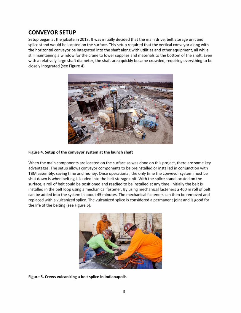
CONVEYOR SETUP Setup began at the jobsite in 2013. It was initially decided that the main drive, belt storage unit and splice stand would be located on the surface. This setup required that the vertical conveyor along with the horizontal conveyor be integrated into the shaft along with utilities and other equipment, all while still maintaining a window for the crane to lower supplies and materials to the bottom of the shaft. Even with a relatively large shaft diameter, the shaft area quickly became crowded, requiring everything to be closely integrated (see Figure 4).
Figure 4. Setup of the conveyor system at the launch shaft When the main components are located on the surface as was done on this project, there are some key advantages. The setup allows conveyor components to be preinstalled or installed in conjunction with TBM assembly, saving time and money. Once operational, the only time the conveyor system must be shut down is when belting is loaded into the belt storage unit. With the splice stand located on the surface, a roll of belt could be positioned and readied to be installed at any time. Initially the belt is installed in the belt loop using a mechanical fastener. By using mechanical fasteners a 460 m roll of belt can be added into the system in about 45 minutes. The mechanical fasteners can then be removed and replaced with a vulcanized splice. The vulcanized splice is considered a permanent joint and is good for the life of the belting (see Figure 5).
Figure 5. Crews vulcanizing a belt splice in Indianapolis
5

THE CONVEYOR IN OPERATION Excavated rock was removed with the horizontal and vertical conveyor system between 2013 and 2015. With over 10,668 tunnel meters of conveyer installed in the tunnel, another 76 meters going up the shaft, and the ability to store or let out 609 meters of conveyor from a surface mounted storage unit, the system was vast and complex. At the shaft bottom, the loaded belt discharged onto a vertical bucket belt to be hauled up the shaft and deposited onto a stacking conveyor (see Figure 6).
Figure 6. Stacker conveyor for temporary storage of muck Power to the loaded horizontal belt was supplied through a series of boosters with 149 kW drive assemblies. The unloaded belt was powered by return boosters, again with 149 kW drives. The surface storage unit provided easy access to the belt for inspection, and allowed belt to be loaded into the system without having to lower rolls of conveyor down into the shaft or starter tunnel as the TBM advanced. Splices were done by trained crews at the surface in a sheltered enclosure, and mechanical splices were kept to an absolute minimum, with mechanical splices replaced by vulcanized splices. A 37 kW electric motor that was excited by a small variable frequency drive was used to supply tension in the system at the storage unit, and again, with no moving parts other than the cable due to the use of the VFDs. Each drive assembly underground was powered by an individual VFD as well. Each drive was monitored at the surface by PLC systems tied into a fiber optic cable, with Ethernet access available from the surface. For the system start up under loaded conditions, various parameters such as timing between boosters, ramp up speeds, belt speeds, and motor loads could be monitored and then altered from an office setting topside, allowing for changes to the system as the belt length increased. By the time the belt had reached its full extension, a total of nine booster drives were installed throughout the tunnel length.
6
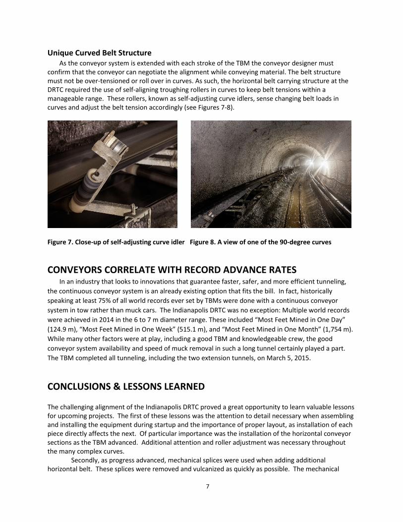
Unique Curved Belt Structure As the conveyor system is extended with each stroke of the TBM the conveyor designer must
confirm that the conveyor can negotiate the alignment while conveying material. The belt structure must not be over-tensioned or roll over in curves. As such, the horizontal belt carrying structure at the DRTC required the use of self-aligning troughing rollers in curves to keep belt tensions within a manageable range. These rollers, known as self-adjusting curve idlers, sense changing belt loads in curves and adjust the belt tension accordingly (see Figures 7-8).
Figure 7. Close-up of self-adjusting curve idler Figure 8. A view of one of the 90-degree curves
CONVEYORS CORRELATE WITH RECORD ADVANCE RATES In an industry that looks to innovations that guarantee faster, safer, and more efficient tunneling,
the continuous conveyor system is an already existing option that fits the bill. In fact, historically speaking at least 75% of all world records ever set by TBMs were done with a continuous conveyor system in tow rather than muck cars. The Indianapolis DRTC was no exception: Multiple world records were achieved in 2014 in the 6 to 7 m diameter range. These included “Most Feet Mined in One Day” (124.9 m), “Most Feet Mined in One Week” (515.1 m), and “Most Feet Mined in One Month” (1,754 m). While many other factors were at play, including a good TBM and knowledgeable crew, the good conveyor system availability and speed of muck removal in such a long tunnel certainly played a part. The TBM completed all tunneling, including the two extension tunnels, on March 5, 2015.
CONCLUSIONS & LESSONS LEARNED The challenging alignment of the Indianapolis DRTC proved a great opportunity to learn valuable lessons for upcoming projects. The first of these lessons was the attention to detail necessary when assembling and installing the equipment during startup and the importance of proper layout, as installation of each piece directly affects the next. Of particular importance was the installation of the horizontal conveyor sections as the TBM advanced. Additional attention and roller adjustment was necessary throughout the many complex curves.
Secondly, as progress advanced, mechanical splices were used when adding additional horizontal belt. These splices were removed and vulcanized as quickly as possible. The mechanical
7

splices created weak points within the belt and were easily able to snag the horizontal belt structure and break. It was best to eliminate these problems before they arose using vulcanized splices.
Finally, and most importantly, it was imperative to have trained and qualified personnel to maintain the belt and belt structure. The belt mechanics were dedicated solely to daily maintenance and adjustment of the belt. Without a properly running conveyor system, the TBM cannot advance.
8